WO2016004739A1 - Radeau semi-submergé à rotation à suivi de vent pour génération d'énergie éolienne et son procédé de construction - Google Patents
Radeau semi-submergé à rotation à suivi de vent pour génération d'énergie éolienne et son procédé de construction Download PDFInfo
- Publication number
- WO2016004739A1 WO2016004739A1 PCT/CN2014/094666 CN2014094666W WO2016004739A1 WO 2016004739 A1 WO2016004739 A1 WO 2016004739A1 CN 2014094666 W CN2014094666 W CN 2014094666W WO 2016004739 A1 WO2016004739 A1 WO 2016004739A1
- Authority
- WO
- WIPO (PCT)
- Prior art keywords
- raft
- wind
- power generation
- floater
- generation unit
- Prior art date
- Legal status (The legal status is an assumption and is not a legal conclusion. Google has not performed a legal analysis and makes no representation as to the accuracy of the status listed.)
- Ceased
Links
Images




Classifications
-
- F—MECHANICAL ENGINEERING; LIGHTING; HEATING; WEAPONS; BLASTING
- F03—MACHINES OR ENGINES FOR LIQUIDS; WIND, SPRING, OR WEIGHT MOTORS; PRODUCING MECHANICAL POWER OR A REACTIVE PROPULSIVE THRUST, NOT OTHERWISE PROVIDED FOR
- F03D—WIND MOTORS
- F03D7/00—Controlling wind motors
- F03D7/02—Controlling wind motors the wind motors having rotation axis substantially parallel to the air flow entering the rotor
- F03D7/0204—Controlling wind motors the wind motors having rotation axis substantially parallel to the air flow entering the rotor for orientation in relation to wind direction
-
- B—PERFORMING OPERATIONS; TRANSPORTING
- B63—SHIPS OR OTHER WATERBORNE VESSELS; RELATED EQUIPMENT
- B63B—SHIPS OR OTHER WATERBORNE VESSELS; EQUIPMENT FOR SHIPPING
- B63B1/00—Hydrodynamic or hydrostatic features of hulls or of hydrofoils
- B63B1/02—Hydrodynamic or hydrostatic features of hulls or of hydrofoils deriving lift mainly from water displacement
- B63B1/10—Hydrodynamic or hydrostatic features of hulls or of hydrofoils deriving lift mainly from water displacement with multiple hulls
- B63B1/107—Semi-submersibles; Small waterline area multiple hull vessels and the like, e.g. SWATH
-
- B—PERFORMING OPERATIONS; TRANSPORTING
- B63—SHIPS OR OTHER WATERBORNE VESSELS; RELATED EQUIPMENT
- B63B—SHIPS OR OTHER WATERBORNE VESSELS; EQUIPMENT FOR SHIPPING
- B63B1/00—Hydrodynamic or hydrostatic features of hulls or of hydrofoils
- B63B1/02—Hydrodynamic or hydrostatic features of hulls or of hydrofoils deriving lift mainly from water displacement
- B63B1/10—Hydrodynamic or hydrostatic features of hulls or of hydrofoils deriving lift mainly from water displacement with multiple hulls
- B63B1/12—Hydrodynamic or hydrostatic features of hulls or of hydrofoils deriving lift mainly from water displacement with multiple hulls the hulls being interconnected rigidly
- B63B1/125—Hydrodynamic or hydrostatic features of hulls or of hydrofoils deriving lift mainly from water displacement with multiple hulls the hulls being interconnected rigidly comprising more than two hulls
-
- B—PERFORMING OPERATIONS; TRANSPORTING
- B63—SHIPS OR OTHER WATERBORNE VESSELS; RELATED EQUIPMENT
- B63B—SHIPS OR OTHER WATERBORNE VESSELS; EQUIPMENT FOR SHIPPING
- B63B21/00—Tying-up; Shifting, towing, or pushing equipment; Anchoring
- B63B21/20—Adaptations of chains, ropes, hawsers, or the like, or of parts thereof
-
- B—PERFORMING OPERATIONS; TRANSPORTING
- B63—SHIPS OR OTHER WATERBORNE VESSELS; RELATED EQUIPMENT
- B63B—SHIPS OR OTHER WATERBORNE VESSELS; EQUIPMENT FOR SHIPPING
- B63B21/00—Tying-up; Shifting, towing, or pushing equipment; Anchoring
- B63B21/24—Anchors
- B63B21/26—Anchors securing to bed
-
- B—PERFORMING OPERATIONS; TRANSPORTING
- B63—SHIPS OR OTHER WATERBORNE VESSELS; RELATED EQUIPMENT
- B63B—SHIPS OR OTHER WATERBORNE VESSELS; EQUIPMENT FOR SHIPPING
- B63B21/00—Tying-up; Shifting, towing, or pushing equipment; Anchoring
- B63B21/50—Anchoring arrangements or methods for special vessels, e.g. for floating drilling platforms or dredgers
-
- B—PERFORMING OPERATIONS; TRANSPORTING
- B63—SHIPS OR OTHER WATERBORNE VESSELS; RELATED EQUIPMENT
- B63B—SHIPS OR OTHER WATERBORNE VESSELS; EQUIPMENT FOR SHIPPING
- B63B35/00—Vessels or similar floating structures specially adapted for specific purposes and not otherwise provided for
- B63B35/44—Floating buildings, stores, drilling platforms, or workshops, e.g. carrying water-oil separating devices
-
- F—MECHANICAL ENGINEERING; LIGHTING; HEATING; WEAPONS; BLASTING
- F03—MACHINES OR ENGINES FOR LIQUIDS; WIND, SPRING, OR WEIGHT MOTORS; PRODUCING MECHANICAL POWER OR A REACTIVE PROPULSIVE THRUST, NOT OTHERWISE PROVIDED FOR
- F03D—WIND MOTORS
- F03D13/00—Assembly, mounting or commissioning of wind motors; Arrangements specially adapted for transporting wind motor components
- F03D13/20—Arrangements for mounting or supporting wind motors; Masts or towers for wind motors
- F03D13/25—Arrangements for mounting or supporting wind motors; Masts or towers for wind motors specially adapted for offshore installation
-
- F—MECHANICAL ENGINEERING; LIGHTING; HEATING; WEAPONS; BLASTING
- F03—MACHINES OR ENGINES FOR LIQUIDS; WIND, SPRING, OR WEIGHT MOTORS; PRODUCING MECHANICAL POWER OR A REACTIVE PROPULSIVE THRUST, NOT OTHERWISE PROVIDED FOR
- F03D—WIND MOTORS
- F03D9/00—Adaptations of wind motors for special use; Combinations of wind motors with apparatus driven thereby; Wind motors specially adapted for installation in particular locations
- F03D9/20—Wind motors characterised by the driven apparatus
- F03D9/25—Wind motors characterised by the driven apparatus the apparatus being an electrical generator
-
- B—PERFORMING OPERATIONS; TRANSPORTING
- B63—SHIPS OR OTHER WATERBORNE VESSELS; RELATED EQUIPMENT
- B63B—SHIPS OR OTHER WATERBORNE VESSELS; EQUIPMENT FOR SHIPPING
- B63B21/00—Tying-up; Shifting, towing, or pushing equipment; Anchoring
- B63B21/20—Adaptations of chains, ropes, hawsers, or the like, or of parts thereof
- B63B2021/203—Mooring cables or ropes, hawsers, or the like; Adaptations thereof
-
- B—PERFORMING OPERATIONS; TRANSPORTING
- B63—SHIPS OR OTHER WATERBORNE VESSELS; RELATED EQUIPMENT
- B63B—SHIPS OR OTHER WATERBORNE VESSELS; EQUIPMENT FOR SHIPPING
- B63B35/00—Vessels or similar floating structures specially adapted for specific purposes and not otherwise provided for
- B63B35/44—Floating buildings, stores, drilling platforms, or workshops, e.g. carrying water-oil separating devices
- B63B2035/4433—Floating structures carrying electric power plants
- B63B2035/446—Floating structures carrying electric power plants for converting wind energy into electric energy
-
- F—MECHANICAL ENGINEERING; LIGHTING; HEATING; WEAPONS; BLASTING
- F05—INDEXING SCHEMES RELATING TO ENGINES OR PUMPS IN VARIOUS SUBCLASSES OF CLASSES F01-F04
- F05B—INDEXING SCHEME RELATING TO WIND, SPRING, WEIGHT, INERTIA OR LIKE MOTORS, TO MACHINES OR ENGINES FOR LIQUIDS COVERED BY SUBCLASSES F03B, F03D AND F03G
- F05B2240/00—Components
- F05B2240/90—Mounting on supporting structures or systems
- F05B2240/93—Mounting on supporting structures or systems on a structure floating on a liquid surface
-
- F—MECHANICAL ENGINEERING; LIGHTING; HEATING; WEAPONS; BLASTING
- F05—INDEXING SCHEMES RELATING TO ENGINES OR PUMPS IN VARIOUS SUBCLASSES OF CLASSES F01-F04
- F05B—INDEXING SCHEME RELATING TO WIND, SPRING, WEIGHT, INERTIA OR LIKE MOTORS, TO MACHINES OR ENGINES FOR LIQUIDS COVERED BY SUBCLASSES F03B, F03D AND F03G
- F05B2240/00—Components
- F05B2240/90—Mounting on supporting structures or systems
- F05B2240/95—Mounting on supporting structures or systems offshore
-
- F—MECHANICAL ENGINEERING; LIGHTING; HEATING; WEAPONS; BLASTING
- F05—INDEXING SCHEMES RELATING TO ENGINES OR PUMPS IN VARIOUS SUBCLASSES OF CLASSES F01-F04
- F05B—INDEXING SCHEME RELATING TO WIND, SPRING, WEIGHT, INERTIA OR LIKE MOTORS, TO MACHINES OR ENGINES FOR LIQUIDS COVERED BY SUBCLASSES F03B, F03D AND F03G
- F05B2240/00—Components
- F05B2240/90—Mounting on supporting structures or systems
- F05B2240/97—Mounting on supporting structures or systems on a submerged structure
-
- F—MECHANICAL ENGINEERING; LIGHTING; HEATING; WEAPONS; BLASTING
- F05—INDEXING SCHEMES RELATING TO ENGINES OR PUMPS IN VARIOUS SUBCLASSES OF CLASSES F01-F04
- F05B—INDEXING SCHEME RELATING TO WIND, SPRING, WEIGHT, INERTIA OR LIKE MOTORS, TO MACHINES OR ENGINES FOR LIQUIDS COVERED BY SUBCLASSES F03B, F03D AND F03G
- F05B2270/00—Control
- F05B2270/10—Purpose of the control system
- F05B2270/20—Purpose of the control system to optimise the performance of a machine
-
- Y—GENERAL TAGGING OF NEW TECHNOLOGICAL DEVELOPMENTS; GENERAL TAGGING OF CROSS-SECTIONAL TECHNOLOGIES SPANNING OVER SEVERAL SECTIONS OF THE IPC; TECHNICAL SUBJECTS COVERED BY FORMER USPC CROSS-REFERENCE ART COLLECTIONS [XRACs] AND DIGESTS
- Y02—TECHNOLOGIES OR APPLICATIONS FOR MITIGATION OR ADAPTATION AGAINST CLIMATE CHANGE
- Y02E—REDUCTION OF GREENHOUSE GAS [GHG] EMISSIONS, RELATED TO ENERGY GENERATION, TRANSMISSION OR DISTRIBUTION
- Y02E10/00—Energy generation through renewable energy sources
- Y02E10/70—Wind energy
- Y02E10/72—Wind turbines with rotation axis in wind direction
-
- Y—GENERAL TAGGING OF NEW TECHNOLOGICAL DEVELOPMENTS; GENERAL TAGGING OF CROSS-SECTIONAL TECHNOLOGIES SPANNING OVER SEVERAL SECTIONS OF THE IPC; TECHNICAL SUBJECTS COVERED BY FORMER USPC CROSS-REFERENCE ART COLLECTIONS [XRACs] AND DIGESTS
- Y02—TECHNOLOGIES OR APPLICATIONS FOR MITIGATION OR ADAPTATION AGAINST CLIMATE CHANGE
- Y02E—REDUCTION OF GREENHOUSE GAS [GHG] EMISSIONS, RELATED TO ENERGY GENERATION, TRANSMISSION OR DISTRIBUTION
- Y02E10/00—Energy generation through renewable energy sources
- Y02E10/70—Wind energy
- Y02E10/727—Offshore wind turbines
Definitions
- the example embodiments in general are directed to a wind tracing rotational semi-submerged raft for wind power generation deposited in a body of water supporting a plurality of wind turbines facing into wind to generate electricity and its application in offshore wind farms, and to a fabrication and construction method thereof.
- Wind energy is an unlimited green energy resource which receives great attention. Offshore wind power generation is more attractive than its land-based counterpart due to its beneficial stronger and static winds.
- offshore wind farms are moving from near-shore to far-shore locations. In the large open space of the far-shore, the wind is strong and stable, and since the turbines are essentially invisible on shore, opposition from the surrounding community is minimal.
- Offshore wind farms can be classified as fixed, bottom-type and floating-type wind farms. The former fixes the foundation of the wind turbine to the seabed.
- the floating-type wind farm is a natural choice for offshore deep water wind farms, since a fixed foundation in a deep water zone is not feasible and the construction risk is substantially high.
- Tension leg In this method, the floating platform is tied down by cable lines to the seabed anchor in order to resist the uplifting forces induced by floatation of the platform, such that the overturning moment is absorbed into a variation in the tension of the cable lines.
- An example tension leg system is embodied by the Blue H Group Technologies, Ltd. ( “Blue H” ) floating platform developed in the United Kingdom;
- Adjustable water-ballasting floater system In this process, the water ballast between floaters of a floating platform is adjusted to balance the overturning moment.
- An example water-ballasting floater system is embodied by the floating platform manufactured by Principle Power Inc. out of Seattle, Washington; and the
- HyWind Spar platform Marketed by HYWIND TM , this floating offshore spar buoy wind turbine system based on the OC3 Hywind concept is designed to have its center of gravity located below the float center by using a steel rod extended from the bottom of the platform to the deep sea with a heavy mass attached to the end of the rod so as to lower the combined center of gravity below the float center.
- the steel rod of the HyWind spar buoy is over 100m; therefore it is only suited for deep water environment.
- the above-noted conventional wind farms are formed by a plurality of single floating turbines dispersed in a vast stretch of ocean. If the wind field has a dominant wind direction, the wind turbine spacing in the perpendicular direction of the wind can be taken as 1.8D to 3.0D, whereas the turbine spacing in the direction along the wind has to increase to 6.0D to 10D, where D is the diameter of the rotor blades of the turbine. This great separation is adapted to avoid the wake shadow that the upwind turbines cast on the downwind turbines. The wake shadow effects cause a potential power loss in the downwind turbines, and also present a fatigue load on the downwind turbines.
- the spacing between turbines is maintained too short, the losses from the wake effect will be substantial. Therefore, the spacing is maintained at a minimum of 6.0D.
- the rotor diameter is over 50m. In this case, the spacing distance will be 300m to 500m.
- the underwater cable linking the turbines is a great length; the resistance of this substantially long cable will cause a loss in the power transmission.
- the wind at sea usually has no dominant direction.
- the turbine rotor In order to catch the maximum wind energy, the turbine rotor should be perpendicular to the wind direction.
- the concept of placing several turbines on a rotational platform has evolved.
- the WINDSEA TM concept developed by WINDSEA AS of Norway consists of a floating device supporting three (3) wind turbines.
- the configuration of the floater is of a semi-submersible vessel type with three (3) corner columns, each column supporting one wind turbine thereon.
- This configuration essentially places three turbines on a triangular platform with a turning axis located in the geometric center. In this configuration, the platform may easily be overturned since there is no self-restoring moment; this is because the turning center is also the geometric center.
- EP 1366290 B1 entitled “OFFSHORE FLOATING WIND POWER GENERATION PLANT” by applicant Ishikawajima-Harima Jukogyo Kabushiki Kaisha describes a floating wind power generation plant that turns around a turret that is connected to the platform with a rigid arm while multiple mooring lines are fixed to the turret. This platform cannot be pre-sunk to set up tension in the mooring lines, hence it is easily disturbed by waves. This rigid arm will transfer the dynamic load on the platform to the turret, thereby creating a fatigue problem.
- HEXICON TM AB of Sweden is currently testing a multi-turbine floating structure with the turret located at the center of gravity and the turn is by electric power.
- An example embodiment of the present invention is directed to a semi-submergible raft wind power generation unit.
- the raft wind power generation unit includes at least three floaters and at least three wind turbines configured for placement on the floaters.
- the raft is adapted to turn about a vertical axis and be fixed to a seabed by a mooring line. Additionally, a force resultant from a wind load on the raft passes closely around the center of geometry thereof, which is a distance away from the center of rotation thereof so that a yaw moment about the center of rotation is created which rotates the raft until the force resultant passes through the center of geometry and center of rotation.
- Another example embodiment is directed to a construction method for fabrication of a semi-submergible raft wind power generation unit.
- a plurality of beam segments that make up at least three floaters and their associated connection beams are match casted. Ends of the beam segments are sealed and then transported to an assembly site at a harbor by land or by sea. At least three piles per floater are sunk at a location where a floater is to be positioned at the assembly site, the at least three piles serving as guiding piles to confine the location of the floater.
- a first bottom floater segment is then temporarily fixed inside a space bounded by the guiding piles, and the floater and connection beam segments are assembled either on land or in the water.
- the assembled beams are brought to a joint position of the floaters and the assembled beams are temporarily fixed to the guiding piles. Then, a steel mold is set up and a gap between the steel mold and the floater and beam surfaces is sealed. Water is then pumped out of the steel mold, reinforcement is fixed in the joint at the floaters, and concrete is cast in the mold, the wet concrete thereafter cured. Once the concrete has reached its design strength, the floater and connection beams that have been temporarily fixed at the guiding piles are freed. A next floater segment is then loaded onto the first bottom segment and connected thereto with an epoxy coated joint together with pre-stressed steel bars.
- the loading and connecting steps are repeated until the last floater segment has been connected, and then a wind turbine is installed on the floater.
- a cable is attached to the bottom end of each floater, with the free ends of the cables brought to a meeting point.
- the meeting point is at the center of a socket joint for the connection of the cables and a mooring line to the floater bottom and to a seabed anchor.
- the location of the meeting point does not coincide with the center of gravity of the formed raft unit, but rather is offset from the center of gravity at a distance into the windward side of the raft unit.
- FIGS. 1A and 1B illustrate traditional 6x6 and 3x4 layouts of wind farms in accordance with an example embodiment.
- FIG. 2 is a plan view of a triangular semi-submerged raft wind power generation unit in accordance with an example embodiment.
- FIG. 3 is a sectional view 1-1 of FIG. 2.
- FIG. 4 is a sectional view 2-2 of FIG. 2.
- FIG. 5 is a diagram illustrating how the triangular semi-submerged raft wind power generation unit rotates into a facing wind upon a sudden change of wind direction.
- FIG. 6 is a plan view of a star-shaped semi-submerged raft wind power generation unit according to another example embodiment.
- FIG. 7 is a sectional view 1-1 of FIG. 6.
- FIG. 8 is a sectional view 2-2 of FIG. 6.
- FIG. 9 is a diagram illustrating how the star-shaped semi-submerged raft wind power generation unit rotates upon a sudden change of wind direction.
- FIG. 10 is a plan view of a T-shaped semi-submerged raft wind power generation unit according to another example embodiment.
- FIG. 11 is a sectional view 1-1 of FIG. 10.
- FIG. 12 is a sectional view 2-2 of FIG. 10.
- FIG. 13 is a plan view of the wind tracing rotational semi-submerged raft wind power generation unit in a trapezoidal layout.
- FIG. 14 is a sectional view 1-1 of FIG. 13.
- FIG. 15 is a sectional view 2-2 of FIG. 13.
- FIGS. 16A and 16B illustrate how the semi-submerged raft wind power generation unit rotates to align in the wind direction after a sudden change of wind direction.
- FIG. 17 is an elevation view to illustrate an optional conic body being added to the bottom of the floater for landing on the seabed.
- FIG. 18 is a diagram illustrating how the triangular semi-submerged raft wind power generation unit rotates 360°to loosen a twisted power cable.
- FIG. 19 is a diagram illustrating fabrication steps (A) through (D) in the assembly and construction of the wind tracing, rotational, semi-submerged raft wind power generation unit in accordance with the example embodiments.
- FIG. 20 is a front view to illustrate how the semi-submerged raft wind power generation unit sinks into the water and drops ship anchor onto the seabed in order to stabilize the raft against storm attack.
- floater refers to a floating structure in a body of water on which a wind power turbine may be mounted thereon.
- the example embodiments to be more fully described hereafter are directed to a wind tracing, rotational semi-submerged raft wind power generation unit.
- the semi-submerged raft wind power generation unit or “raft” includes a plurality of at least three hollow, closed cylindrical columns known as floaters which are deposited in and float in a body of water. These floaters are interconnected by a plurality of underwater beams to form an underwater plane frame with the floater situated in the node of the plane frame, thus forming a semi-submerged raft supporting one or more wind turbines on the selected floaters.
- the raft may be safely anchored to a seabed by a single mooring line that enables the raft to turn along with the wind, so that the wind turbines on the raft are full time wind facing without casting their wake shadow on leeward turbines.
- the adjacent turbines may be placed in a closer manner, say 1.8D to 2.2D where D is the diameter of the rotor.
- an underwater marine power cable carrying the electricity generated by the turbines can be shortened up to 50%.
- the example semi-submerged rafts are very competitive in deep water zones for wind power generation development.
- the raft design life may exceed 100 years, as compared with a steel platform which is designed for only 25 ⁇ 30 years. Accordingly, the lifetime costs of the present example embodiments are even less expansive and drastically lower than that attributed to the steel platform. This will enable floating wind farms in far shore deep sea applications to be realized much earlier than expected.
- FIGS. 1A and 1B illustrate traditional 6x6 and 3x4 layouts of wind farms in accordance with an example embodiment.
- FIG. 1A shows a wind farm of 36, 5MW wind turbines supported by 36 floating platforms in the traditional manner.
- the total installation capacity is 6 ⁇ 6 ⁇ 5MW or 180MW.
- the distance between adjacent wind turbines is taken as 7.0D where D is the diameter of the rotor and in this case is 120m, so the distance is 840m and the total marine cable length in the least complex form is 6x (5x840) +5x840 or 29.4 km.
- FIG. 1B shows the same turbines supported by the semi-submerged raft units wind power generation units in accordance with the example embodiments; atotal of 12 units are required.
- Installation capacity is 12 ⁇ 3 ⁇ 5 or 180 MW.
- the marine cable needed in the least complex form is 3x (3x1200) +sx1200 or 13.2 km. It is clear that for the same installation capacity, the amount of marine cable needed for the example embodiment layout can be reduced by up to 50%.
- the 3X4 layout also lowers the transmission loss as the cable length is greatly reduced.
- the basic configurations of the example wind tracing rotational semi-submerged raft wind power generation units are described in four different types, namely a triangle, star and a tee (T) configuration as one group for three (3) wind turbines, and a trapezoidal configuration of five (5) wind turbines. It should be understood that any person skilled in the art may derive configurations other than these four basic types, and should be aware that the application of the present example embodiments is not limited to those outlined herein.
- FIG. 2 is a plan view of a triangular semi-submerged raft wind power generation unit in accordance with an example embodiment
- FIG. 3 is a sectional view 1-1 of FIG. 2
- FIG. 4 is a sectional view 2-2 of FIG. 2
- FIG. 5 is a diagram illustrating how the triangular semi-submerged raft wind power generation unit rotates into a facing wind upon a sudden change of wind direction.
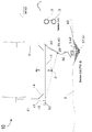
- raft 10 a triangular configuration of a wind tracing rotational semi-submerged raft wind power generation unit 10 (hereafter “raft 10” ) which includes, at each vertex of the triangle, a floater 12 that is connected by underwater beams 13 below the water surface 1.
- the connection beam 13 may be in a depth of 14m or more below the water surface 1. In this way, a wave has almost no effect on the beams 13.
- the floater 12 and the connection beams 13 form a semi-submerged raft.
- the tower of the wind turbine 21 is erected from a working platform 17 in each floater 12; the nacelles of the wind turbines 21 are then installed on the tower.
- two wind turbines 21 are in a front row to face the wind, leaving the third wind turbine in the aft or leeward side.
- the triangle may be an equilateral triangle with the sides proportioned so that the wake shadow of the front turbine does not cast on the third turbine behind it. The wake shadow is thus dispersed at a gentle slope. According to this slope, separation between the turbines 21 can be determined.
- diagonal struts 14 and 15 are used at the corners between the floater 12 and the connection beams 13, to strengthen the corner.
- the size of beams 13 is dependent on the requirement of the stiffness of the beams 13 that are needed to limit the rotation of the floater 12 (i.e. the rotation of the wind turbine 21 tower) .
- the rotation of the tower should not be greater than 10°.
- the floater 12 If the floater 12 is taken as having a 10m diameter, the floater 12 needs to move 3.7m to generate 288t in order to balance the wind load.
- the rigid body rotation is only 0.8°, the elastic rotation is 2°, and hence the combined rotation is 3°. If the two opposite floaters 12 move ⁇ 4m by the wave, rotation thus calculated is 3°per floater 12, or a total is 6°which is still within the limit of 10°maximum. It can be seen that the raft 10 is very stable.
- cables 31, 32 are attached to the floater 12 bottom at one end and to a meeting point at the center of a socket joint 35 at the other end.
- the cables 31, 32 run at a slope to the meeting point 35, which is at an offset distance from the C.G. (center of geometry or in this case it is also the center of gravity) of the triangle along the bisector of the triangle between the C.G. and the bisector side.
- the socket joint 35 is connected to a vertically fixed mooring line 36 which is connected to a seabed anchor 37 so that socket joint 35 allows the raft 10 to turn by twisting the mooring line 36. Cables 31, 32 and mooring line 36 are in equilibrium.
- the turning axis is denoted by element 39.
- Two methods for fixing the triangular semi-submerged raft 10 are used for different purposes.
- a one point anchorage may be used. This may be a one-cable tension leg or just a cable without tension.
- the tension in the mooring line 36 and the cables 31, 32 are achieved by sinking the raft 10 to a pre-determined depth, tightening the mooring line 36 to the seabed anchor 37, and finally raising the raft 10 by pumping out the water ballast.
- the raft 10 is restrained by the length of the mooring line 36, thus setting up tension forces in the mooring line 36 and cables 31, 32.
- multiple anchor points are used to stabilize the raft 10. This is achieved by dropping the ship anchors 54 stored in each floater 12 to the seabed to stabilize the raft 10. After passing of the storm, these anchors 54 are raised and stored in the floater 12. The raft 10 returns to a normal operation state.
- the bottom of the floater 12 is attached to a landing gear. Since the self weight of the raft 10 is balanced by the floatation, the sitting force is small and controllable, the landing gear is taken as a downward pointing conic object 16 such that it can penetrate into the seabed 2 to increase its resistance to horizontal forces (refer to FIG. 17) .
- cables 31, 32 and mooring line 36 are socketed into the socket joint 35.
- the socket joint 35 is located away from the center of geometry 50 and closer to the bisector side.
- FIG. 5 internal diagrams (1) to (6) are provided in order to help explain the mechanism of the wind tracing rotational semi-submerged raft 10.
- the raft 10 starts at time zero facing north into the incoming wind. In this example the wind suddenly changes to southeast.
- FIG. 5 (1) shows that the S-E wind has its wind force resultant vector acting on the C.G. 50, so it induces a clockwise yaw moment about the vertical turning axis 39 located at the center of socket joint 35.
- the resultant force will pass through the center of geometry 50 which in this case coincides with the center of gravity of the raft 10.
- the aerodynamic force resultant fluctuates around the C.G. 50, however, it is unlikely to cross over the socket joint 35 as the turbulence in the wind will be so large that this case is unlikely to occur in a normal operational wind condition.
- FIG. 5 internal diagrams (2) - (6) demonstrate the principle of wind tracing by assuming the wind force resultant vector acting at the C.G. 50 in a perfectly uniform wind condition, fluctuations in the wind cause the wind force resultant to fluctuate around the C.G. 50, yet still produces a clockwise yaw moment about the vertical turning axis 39 located in the center of socket joint 35.
- This turning mechanism is also true if the wind flow is replaced by an ocean underwater incoming current, as the center of geometry 50 in both cases are identical. If the current is significant, the rotor of the turbine 21 is either oriented at an angle to the wind in order to generate a force to counter-balance the underwater current force, or to completely eliminate the effects of the underwater current on raft 10.
- the latter is achieved by installing a rudder 52 in the leeward floater 12 and navigating the rudder 52 in order to balance the current force, thus eliminating the current effects on raft 10.
- the size of the rudder 52 is determined by the current strength.
- the rudder 52 has another function as it could offer a damping effect to the fluctuating wind force that may cause the raft 10 to yaw and oscillate.
- the example wind tracing rotational semi-submerged raft 10 does not require external power to turn the turbine 21 into the wind.
- the turbine 21 is turned by nature, i.e., by the wind. This configuration is thus economical and simple in its maintenance requirements.
- the eccentricity of the socket joint 35 away from the center of geometry 50 may be adjusted. Basically, it is adjusted by the length of cables 31 and 32. The larger the distance, the greater the yaw moment induced
- FIG. 6 is a plan view of a star-shaped semi-submerged raft wind power generation unit according to another example embodiment
- FIG. 7 is a sectional view 1-1 of FIG. 6
- FIG. 8 is a sectional view 2-2 of FIG. 6
- FIG. 9 is a diagram illustrating how the star-shaped semi-submerged raft wind power generation unit rotates upon a sudden change of wind direction.
- this embodiment is similar in many respects to the triangular configuration shown and described in FIGS. 2-5, only the differences are discussed in detail. Referring to FIGS.
- the star-shaped semi-submerged raft wind power generation unit 10’ configuration (hereafter raft 10’ ) is a variation of the triangle configuration, in which the sides of the triangle are replaced by tensioned cables 22 and the beams 13 are replaced by three-pointed arms connected between the center of geometry 50 and the floaters 12 in the vertices of the triangle. The floaters 12 remain in the vertices. Diagonal struts 14, 15 are used to strengthen the connection between the floater 12 and the arm.
- the layouts of the front turbines 21 also cause no wake effect on the leeward turbine 21.
- cables 31 and 32 are each connected at one end to the bottom of the floater 12 and the other end is socketed into the socket joint 35, offset from the C.G. 50 at a distance to be designed and towards the windward side.
- the rotor plane of two turbines 21 on the windward side is normal to the wind direction, whereas the third turbine 21 is on the leeward side symmetrically placed between the windward turbines 21, see FIG. 6 for example.
- a vertically connected mooring line 36 connects the socket joint 35 and seabed anchor 37 in the seabed 2.
- cables 31, 32 and the mooring line 36 may be optionally introduced with a tension force forming a single tension leg foundation.
- the turning mechanism is similar to that used in the triangular-shaped raft 10 as described in FIGS. 2-5 and henceforth is not repeated herein.
- Amultiple anchor system may also be used in a storm or typhoon period to stabilize the raft 10’ .
- FIG. 9 outlines the turning mechanism of the star-shaped wind tracing rotational semi-submerged raft wind power generation unit 10’ under the change of wind direction. It is similar to FIG. 5 in principle and hence is not repeated herein. But it is noted here that in FIG. 9,internal diagram (6) shows that the raft 10’ is over turned and a restore moment is set up to return it back to the normal position.
- FIG. 10 is a plan view of a T-shaped semi-submerged raft wind power generation unit according to another example embodiment;
- FIG. 11 is a sectional view 1-1 of FIG. 10;
- FIG. 12 is a sectional view 2-2 of FIG. 10.
- FIGS. 10 through 12 there is shown a variation of the star-shaped configuration of FIGS. 6-9, in which the connection point of the arms to the midpoint of the side joining the two windward floaters is moved so as to form a “T” , hence a T-shaped semi-submerged raft wind power generation unit 10” .
- the arrangement of the cables 31, 32 and the single tension leg mooring line 36 is similar to the previous embodiments and hence is not repeated herein for sake of brevity.
- FIG. 13 is a plan view of the wind tracing rotational semi-submerged raft wind power generation unit in a trapezoidal layout
- FIG. 14 is a sectional view 1-1 of FIG. 13
- FIG. 15 is a sectional view 2-2 of FIG. 13
- FIGS. 16A and 16B illustrate how the semi-submerged raft wind power generation unit rotates to align in the wind direction after a sudden change of wind direction.
- FIGS. 13 through 16B there is shown a trapezoidal-shaped, semi-submerged raft wind power generation unit 10” ’ (hereafter “raft 10” ’ “) .
- Raft 10 includes two (2) rows of floaters 12; awindward row containing three (3) floaters 12 and a leeward row containing five (5) floaters 12.
- a turbine 21 rests on each alternate floater 12, i.e. two turbines 21 in the windward row and three turbines in the leeward row.
- the floaters 12 are interconnected by underwater beams 13 in a generally triangular pattern.
- a rigid arm 70 from the mid-floater 12 of the windward row is extended into the incoming wind and connected to a floater 12.
- Cables 41 and 42 each have one end attached to the bottom of the floaters 12, with their free ends socketed into the socket joint 35 that is located in an offset position relative to the windward row, at a distance into the windward side that is approximately in the middle of the rigid arm 70.
- the mooring line 36 connects the socket joint 35and the seabed anchor 37, allowing turning of the raft 10” ’ by twisting in the mooring line 36.
- a tension leg platform may be formed using a pre-sinking procedure in order to improve the stability of the platform under operating conditions.
- stability during a storm or typhoon period is provided by two methods: the employment of multiple anchors, and the sinking to the seabed procedure (provided the water depth is within certain criteria) .
- FIG. 17 is an elevation view to illustrate an optional conic body being added to the bottom of the floater for landing on the seabed. More specifically, FIG. 17 illustrates a raft 10 that has taken in water so as to sink to the seabed 2 under an extraordinary huge wave attack. This is done to avoid damage to the connection beam 13.
- the bottom of each floater 12 is equipped with a conic object 6 with its apex pointing downward, so that it can penetrate into the seabed 2 to increase the resistance to horizontal forces.
- a prior survey of the seafloor 2 should be carried out, and the area cleared if necessary for landing.
- the raft 10 is raised by pumping out the water and continues with power production.
- the anchors are retracted and the raft 10 is turned by the natural wind in order to face the wind.
- the distance between two adjacent turbines 21 is taken as 1.8D to 2.2D, where D is the diameter of the rotor. For a 5MW turbine where the rotor is 120m, the distance will be in a range of about 216m to 240m.
- the distance between rows of floaters 12 is taken as 1.0D or the height of the tower, whichever is greater.
- the trapezoidal configuration shown in FIGS. 13-16B allows the windward turbines 21 to cast their wake shadows on the empty space in the leeward row of turbines 12, thereby eliminating the wake effects on those turbines 21.
- the size of the floaters12 in the two rows may be different. The main purpose of employing floaters 12 in differing sizes is to have the center of gravity as close as possible to the center of floatation in the horizontal plane.
- the turning mechanism of the trapezoid-shaped raft 10” ’ is similar to that of triangular configuration described with respect to FIGS. 2-5.
- raft 10” ’ will only become stationary when the force resultant of the wind load passes through the vertical turning axis 39 located at the center of socket joint 35, together with the center of geometry 50.
- raft 10” ’ can be turned by aiming the turbine 21 at an angle to the incoming wind using wind force to push the raft 10” ’ to turn.
- the power output cables from the turbines 21 of the raft 10” ’ is grouped into one final output cable 60.
- the final output cable 60 comes out of the raft along one of the structural cables 31 or 32 and along the mooring line 36 to the seabed anchor 37.
- the final power output cable 60 comes out from the raft 10” ’a nd along one of the structural cables 41 and the mooring line 36 to the seabed anchor 37. After that, the power output cable 60 runs over the seabed 2 to the shore or near shore substations.
- a substantially extra long length of the power cable 60 (in the form of loosened coils) is reserved for harmless twisting of the power cable 60 when the raft 10” ’ is turned around the vertical axis 39.
- the raft 10” ’ can also be designed with an active turning capability.
- the on-board computer of the raft 10” ’ may record the circular angle that the raft 10” ’ has turned, and, if the turn is close to the permissible limit and if the wind is predicted to change its direction to force the raft 10” ’ to turn to the permissible limit, the action will be to check with the metrological data if the changing of wind direction lasts for certain period, e.g. days, and the computer will order the raft 10” ’ to conduct an active turn.
- the active turn will orientate one of the turbines 21 to catch the wind force and produce a yaw moment to turn the raft 10” ’ back 360°so that the twisting of the power cable 60 is released in preparation of the coming change of wind direction.
- a ship’s anchor 54 that is installed in each floater 12 will be dropped into the seabed 2 so as to realize a multiple anchor system to prevent raft 10” ’ from turning in the storm.
- the power cable 60 is protected from a damaging twisting action.
- the ship’s anchor 54 is held by two working ropes 53, one being stronger and longer to serve a reserve role in case the other working rope53 fails.
- FIG. 18 is a diagram illustrating how the triangular semi-submerged raft wind power generation unit rotates 360°to loosen a twisted power cable. More specifically, internal diagrams (A) through (H) of FIG. 18 are provided to help explain, based on the triangle configuration, how to turn raft 10 back 360°in an active turn. Initially, if the existing wind direction is north, and the power cable 60 has been twisted counter-clockwise 225°, refer to internal diagram (A) . Based on the metrological forecast, the wind will change to northwest.
- the number of wind turbines in the current invention, the wind tracing rotational semi-submerged raft wind power generation is no restriction theoretically.
- the limitation is how large a floating structure that the technology can handle in the open sea safely.
- the raft structure is preferable in pre-stressed concrete hollow beam 13 and floater 12, otherwise if using steel, heavy ballast has to be used in order to reach the semi-submerged state.
- the construction method is similar to that of bridge using segmental construction method. Select a harbor with adequate water depth to receive the semi-submerged raft. Using the aforementioned assembly method, the raft is assembled in the harbor with the help of temporary guiding piles 48. The completed raft is preferable to have the turbines installed before it is towed to the site.
- FIG. 1 (B) At the wind farm site, a number of the raft units are installed as shown in FIG. 1 (B) .
- the power production efficiency is improved by the full time wind facing turbines, also the submarine cable has been shortened giving an efficient power transmission.
- the seabed gravity anchor 37 is designed to ensure that it is not displaced substantially during the storm period.
- One of the possible method as shown in FIGS. 3 and 4 is to excavate a deep ditch 3 in the seabed 2, and lower the gravity anchor 37 in the ditch 3. If the gravity anchor tries to leave the ditch 3, it has to move upward and this movement requires great energy. The weight of the anchor 37 is therefore should be greater than the uplifting force by the storm by an allowable margin.
- Another method is as shown in FIGS. 7 and 8 that at the anchorage location, raking piles 16 are driven into the seabed 2 to form a ring around the location and the piles 16 protrude out of the seafloor 2. The gravity anchor 37 is then lowered into the anchorage location surrounded by the protruding piles 16. Similarly, the weight of the anchor 37 is therefore should be greater than the uplifting force by the storm by an allowable margin.
- the design is to ensure that the pile allowable tension capacity will not be exceeded by the action of the storm.
- FIG. 19 is a diagram illustrating fabrication steps (A) through (D) in the assembly and construction of the wind tracing, rotational, semi-submerged raft wind power generation unit in accordance with the example embodiments.
- the example method of fabrication as described in FIG. 19 may include one or more of the following steps:
- a short length (e.g., about 1.5 ⁇ 2.0m) of each beam 13 at its two ends joining the floaters 12 is left uncast with reinforcement protruding out for future connection to the floaters 12;
- substep (C) (1) floating in a first floater segment 12A, lowering the segment 12A into the space bounded by the guiding piles 48, and fixing floater segment 12A to the piles 48 after checking the level and verticality of the segment 12A;
- the beam 13 should be made shorter, e.g., 2m shorter on each end for insitu concrete casting;
- the foundation could be a piled foundation, but a caisson foundation is more convenient and this requires the excavation of a large ditch in the seabed 2 to accommodate the caisson.
- a caisson foundation is more convenient and this requires the excavation of a large ditch in the seabed 2 to accommodate the caisson.
- employing a caisson inside a ring of raking piles 16 is another option;
- FIG. 20 is an elevation view to illustrate how the semi-submerged raft wind power generation unit sinks into the water and drops ship’s anchor onto the seabed in order to stabilize the raft against a storm attack.
- the estimated installed rate is at par of the upper limit of land-based wind farms.
- Conventional fixed bottom, near shore, wind farms costs 1.5-2.0 times those of land-based ones to install complete.
- the far shore option is open and can be deployed with a large number of floating wind farms.
- the example embodiments are particularly suitable to the energy requirement of future ocean cities.
- the far shore wind speed is steady and strong and the number of utilization hours is high, thus power generation is also high and steady.
- the pre-stressed concrete structure can last more than 100 years, much more than the floating steel platform which has a design life of 25 ⁇ 30 years. If using whole life costing as a bench mark, the same concrete structure can support four generations of wind turbines. The spread construction cost is even less. Accordingly, the example embodiments can aid realization of a far shore wind farm at a much fast pace.
- the zero emissions, the low cost, high efficiency, and environmental friendliness are some of the highlights of the example embodiments of the present invention.
Landscapes
- Engineering & Computer Science (AREA)
- Chemical & Material Sciences (AREA)
- Combustion & Propulsion (AREA)
- Mechanical Engineering (AREA)
- Ocean & Marine Engineering (AREA)
- General Engineering & Computer Science (AREA)
- Sustainable Development (AREA)
- Sustainable Energy (AREA)
- Life Sciences & Earth Sciences (AREA)
- Physics & Mathematics (AREA)
- Fluid Mechanics (AREA)
- Architecture (AREA)
- Civil Engineering (AREA)
- Structural Engineering (AREA)
- Power Engineering (AREA)
- Wind Motors (AREA)
Abstract
Priority Applications (4)
| Application Number | Priority Date | Filing Date | Title |
|---|---|---|---|
| JP2017501273A JP2017521597A (ja) | 2014-07-08 | 2014-12-23 | 風力発電・回転・半潜水型風力発電用ラフトおよびその建設方法 |
| AU2014400184A AU2014400184A1 (en) | 2014-07-08 | 2014-12-23 | Wind tracing, rotational, semi-submerged raft for wind power generation and a construction method thereof |
| US15/324,339 US20170218919A1 (en) | 2014-07-08 | 2014-12-23 | Wind tracing, rotational, semi-submerged raft for wind power generation and a construction method thereof |
| EP14897308.4A EP3166843A1 (fr) | 2014-07-08 | 2014-12-23 | Radeau semi-submergé à rotation à suivi de vent pour génération d'énergie éolienne et son procédé de construction |
Applications Claiming Priority (2)
| Application Number | Priority Date | Filing Date | Title |
|---|---|---|---|
| CN201410323537.1 | 2014-07-08 | ||
| CN201410323537.1A CN105240221B (zh) | 2014-07-08 | 2014-07-08 | 半潜筏式随风转向水上风力发电设备 |
Publications (1)
| Publication Number | Publication Date |
|---|---|
| WO2016004739A1 true WO2016004739A1 (fr) | 2016-01-14 |
Family
ID=55037999
Family Applications (1)
| Application Number | Title | Priority Date | Filing Date |
|---|---|---|---|
| PCT/CN2014/094666 Ceased WO2016004739A1 (fr) | 2014-07-08 | 2014-12-23 | Radeau semi-submergé à rotation à suivi de vent pour génération d'énergie éolienne et son procédé de construction |
Country Status (7)
| Country | Link |
|---|---|
| US (1) | US20170218919A1 (fr) |
| EP (1) | EP3166843A1 (fr) |
| JP (1) | JP2017521597A (fr) |
| CN (1) | CN105240221B (fr) |
| AU (1) | AU2014400184A1 (fr) |
| HK (1) | HK1219994A1 (fr) |
| WO (1) | WO2016004739A1 (fr) |
Cited By (5)
| Publication number | Priority date | Publication date | Assignee | Title |
|---|---|---|---|---|
| CN114604373A (zh) * | 2022-03-11 | 2022-06-10 | 上海勘测设计研究院有限公司 | 一种压载式海上风电整机运输安装船及方法 |
| US11448193B2 (en) * | 2017-11-24 | 2022-09-20 | Carlos Wong | Self-aligning to wind facing floating platform supporting multi-wind turbines and solar for wind and solar power generation and the construction method thereon |
| EP3740677B1 (fr) | 2018-01-19 | 2023-08-09 | Freia Offshore AB | Plateforme d'énergie éolienne flottante doté d'un dispositif à lignes tendues |
| CN117657376A (zh) * | 2023-12-21 | 2024-03-08 | 连云港建港实业有限公司 | 具有自适应防横风结构的组合式水上操作平台 |
| CN119712402A (zh) * | 2024-12-19 | 2025-03-28 | 中国华能集团清洁能源技术研究院有限公司 | 多机头漂浮式海上风力发电机组 |
Families Citing this family (31)
| Publication number | Priority date | Publication date | Assignee | Title |
|---|---|---|---|---|
| WO2017010051A1 (fr) * | 2015-07-16 | 2017-01-19 | パナソニックIpマネジメント株式会社 | Câble électrique |
| DE102015121371B4 (de) * | 2015-12-08 | 2018-11-15 | Aerodyn Consulting Singapore Pte Ltd | Offshore-Windpark |
| CN105882906B (zh) * | 2016-01-31 | 2017-10-17 | 大连理工大学 | 非金属材质的大型海底测量平台及其布放方法 |
| WO2019143283A1 (fr) * | 2018-01-19 | 2019-07-25 | Freia Offshore Ab | Plateforme d'énergie éolienne flottante doté d'un dispositif à lignes tendues |
| WO2019155883A1 (fr) * | 2018-02-07 | 2019-08-15 | キョーラク株式会社 | Ensemble flotteur |
| JP7181450B2 (ja) * | 2018-02-07 | 2022-12-01 | キョーラク株式会社 | フロート集合体 |
| EP3587796A1 (fr) * | 2018-06-28 | 2020-01-01 | Wepfer Technics AG | Éolienne à alignement automatique |
| JP7188011B2 (ja) * | 2018-11-26 | 2022-12-13 | 株式会社Ihi | 水流発電装置及び水流発電装置の補修方法 |
| CN109977537B (zh) * | 2019-03-25 | 2023-05-30 | 中国航发湖南动力机械研究所 | 涡轮叶片和涡轮叶片的制备方法 |
| KR102187626B1 (ko) * | 2019-07-02 | 2020-12-07 | 주식회사 예성오션테크 | 드릴장치 |
| CN113638855B (zh) * | 2020-04-27 | 2023-05-16 | 北京金风科创风电设备有限公司 | 支撑装置以及风力发电机组 |
| NO346633B1 (en) * | 2020-05-29 | 2022-11-07 | Apl Norway As | System for avoiding damage to power cables to and from and within a floating offshore wind power plant |
| CN111911356A (zh) * | 2020-08-26 | 2020-11-10 | 罗来欢 | 风力发电装置 |
| DE102020123375A1 (de) * | 2020-09-08 | 2022-03-10 | Rwe Renewables Gmbh | Schwimmfähige Offshore-Windkraftanlage |
| NO346590B1 (en) | 2020-09-18 | 2022-10-17 | Fred Olsen Ocean Ltd | Wind turbine with floating foundation |
| CN112433065B (zh) * | 2020-12-28 | 2022-12-09 | 佳木斯大学 | 一种计算机辅助的气象监测机器人 |
| CN113184113A (zh) * | 2021-05-26 | 2021-07-30 | 海南浙江大学研究院 | 一种漂浮式风机系泊系统的意外状况应急措施实现方法 |
| CN114673635B (zh) * | 2022-03-31 | 2025-06-13 | 宁波爱思信息技术有限公司 | 一种漂浮式海上背风式风力发电机群 |
| US20230003190A1 (en) * | 2021-07-05 | 2023-01-05 | Advanced Information Services Co., Ltd. | Wind generator and wind generator group |
| WO2023004117A2 (fr) * | 2021-07-22 | 2023-01-26 | Trendsetter Vulcan Offshore, Inc. | Système d'éolienne en mer et procédé d'installation |
| CN114148462A (zh) * | 2021-08-04 | 2022-03-08 | 中国华能集团清洁能源技术研究院有限公司 | 基于单点系泊的半潜浮式平台和偏心式风机系统 |
| CN113854216B (zh) * | 2021-10-30 | 2024-10-01 | 福建工程学院 | 一种柔性连接抗风浪渔排 |
| MX2024006986A (es) * | 2021-12-09 | 2024-06-19 | Intercontinental Energy Holdings Group Ltd | Sistema para recolectar, generar y transmitir energia en escala de gigavatios de una pluralidad de fuentes distribuidas dispersadas en un area. |
| KR102463990B1 (ko) * | 2022-02-07 | 2022-11-07 | 한국해양과학기술원 | 선수동요 저감형 부유식 해상풍력 계류시스템 |
| JP7430859B1 (ja) | 2022-07-27 | 2024-02-14 | 株式会社 セテック | 浮体式洋上風力発電システム |
| US11981402B1 (en) * | 2022-11-01 | 2024-05-14 | Nicholas John Vincent Elisha | Floating system for an offshore wind turbine |
| CN115771595B (zh) * | 2022-12-20 | 2024-11-08 | 中电建海上风电工程有限公司 | 一种新式半潜式升降平台及海上风电吊装方法 |
| CN116538023B (zh) * | 2023-05-29 | 2025-10-31 | 江苏科技大学 | 一种适用于深远海浮式风机储能与锚固的组合式基础 |
| CN117139997B (zh) * | 2023-08-22 | 2025-09-23 | 中水四局(福清)能源装备有限公司 | 一种海上基础漂浮体模块制作工艺流程 |
| CN117465610B (zh) * | 2023-12-27 | 2024-03-19 | 中海油能源发展股份有限公司采油服务分公司 | 水下系泊钢缆的施工方法 |
| JP7620364B1 (ja) * | 2024-10-04 | 2025-01-23 | 株式会社町おこしエネルギー | 洋上風力発電装置及びこの洋上風力発電装置を製造する方法 |
Citations (7)
| Publication number | Priority date | Publication date | Assignee | Title |
|---|---|---|---|---|
| DE20111441U1 (de) * | 2001-07-10 | 2001-10-18 | Schedl, Konrad, 95643 Tirschenreuth | Auftriebskörper für schwimmende und halbschwimmende Windparks |
| JP2002285951A (ja) * | 2001-03-23 | 2002-10-03 | Hitachi Zosen Corp | 洋上風力発電の浮体式基礎構造物 |
| DE20209000U1 (de) * | 2002-06-11 | 2003-04-17 | Kusan, Kristian, Dipl.-Ing., 56564 Neuwied | Windkraftanlage für den Offshorebereich |
| CN102161376A (zh) * | 2003-10-23 | 2011-08-24 | 海风科技有限责任公司 | 发电机组 |
| US20120294681A1 (en) * | 2011-05-20 | 2012-11-22 | Carlos Wong | Floating wind farm with energy storage facility |
| CN103010415A (zh) * | 2011-09-22 | 2013-04-03 | 黄灿光 | 支撑海上风机和海洋能发电机的预应力混凝土浮式平台 |
| WO2014055027A1 (fr) * | 2012-10-05 | 2014-04-10 | Hexicon Ab | Plate-forme flottante et usine électrique comprenant une telle plate-forme flottante |
Family Cites Families (9)
| Publication number | Priority date | Publication date | Assignee | Title |
|---|---|---|---|---|
| DK1366290T3 (da) * | 2001-03-08 | 2007-12-10 | Ishikawajima Harima Heavy Ind | Flydende offshore-vindkraftanlæg |
| JP2003252288A (ja) * | 2002-02-27 | 2003-09-10 | Hitachi Zosen Corp | 洋上風力発電の浮体式基礎構造物 |
| JP2007331414A (ja) * | 2006-06-12 | 2007-12-27 | Shimizu Corp | 浮体構造および該浮体構造の位置制御方法 |
| CN101565091B (zh) * | 2009-05-21 | 2011-06-15 | 上海利策科技有限公司 | 水上风力发电机的安装设备及其施工方法 |
| US20120207600A1 (en) * | 2009-10-21 | 2012-08-16 | Technip France | Floating vertical axis wind turbine module system and method |
| MY163431A (en) * | 2009-12-07 | 2017-09-15 | Hexicon Ab | Floating energy producing plant |
| CN102155352B (zh) * | 2011-03-25 | 2012-10-10 | 张啸 | 漂浮式水上风力发电设备 |
| CN102506012A (zh) * | 2011-11-09 | 2012-06-20 | 汪砚秋 | 锚泊半潜连体底座海上风力发电机组 |
| CN203419250U (zh) * | 2013-07-22 | 2014-02-05 | 中船重工建筑工程设计研究院有限责任公司 | 新型半潜式浮式海上风电平台 |
-
2014
- 2014-07-08 CN CN201410323537.1A patent/CN105240221B/zh not_active Expired - Fee Related
- 2014-12-23 EP EP14897308.4A patent/EP3166843A1/fr not_active Withdrawn
- 2014-12-23 WO PCT/CN2014/094666 patent/WO2016004739A1/fr not_active Ceased
- 2014-12-23 AU AU2014400184A patent/AU2014400184A1/en not_active Abandoned
- 2014-12-23 US US15/324,339 patent/US20170218919A1/en not_active Abandoned
- 2014-12-23 JP JP2017501273A patent/JP2017521597A/ja active Pending
-
2016
- 2016-07-11 HK HK16108095.9A patent/HK1219994A1/zh unknown
Patent Citations (7)
| Publication number | Priority date | Publication date | Assignee | Title |
|---|---|---|---|---|
| JP2002285951A (ja) * | 2001-03-23 | 2002-10-03 | Hitachi Zosen Corp | 洋上風力発電の浮体式基礎構造物 |
| DE20111441U1 (de) * | 2001-07-10 | 2001-10-18 | Schedl, Konrad, 95643 Tirschenreuth | Auftriebskörper für schwimmende und halbschwimmende Windparks |
| DE20209000U1 (de) * | 2002-06-11 | 2003-04-17 | Kusan, Kristian, Dipl.-Ing., 56564 Neuwied | Windkraftanlage für den Offshorebereich |
| CN102161376A (zh) * | 2003-10-23 | 2011-08-24 | 海风科技有限责任公司 | 发电机组 |
| US20120294681A1 (en) * | 2011-05-20 | 2012-11-22 | Carlos Wong | Floating wind farm with energy storage facility |
| CN103010415A (zh) * | 2011-09-22 | 2013-04-03 | 黄灿光 | 支撑海上风机和海洋能发电机的预应力混凝土浮式平台 |
| WO2014055027A1 (fr) * | 2012-10-05 | 2014-04-10 | Hexicon Ab | Plate-forme flottante et usine électrique comprenant une telle plate-forme flottante |
Cited By (7)
| Publication number | Priority date | Publication date | Assignee | Title |
|---|---|---|---|---|
| US11448193B2 (en) * | 2017-11-24 | 2022-09-20 | Carlos Wong | Self-aligning to wind facing floating platform supporting multi-wind turbines and solar for wind and solar power generation and the construction method thereon |
| EP3740677B1 (fr) | 2018-01-19 | 2023-08-09 | Freia Offshore AB | Plateforme d'énergie éolienne flottante doté d'un dispositif à lignes tendues |
| CN114604373A (zh) * | 2022-03-11 | 2022-06-10 | 上海勘测设计研究院有限公司 | 一种压载式海上风电整机运输安装船及方法 |
| CN114604373B (zh) * | 2022-03-11 | 2023-05-12 | 上海勘测设计研究院有限公司 | 一种压载式海上风电整机运输安装船及方法 |
| CN117657376A (zh) * | 2023-12-21 | 2024-03-08 | 连云港建港实业有限公司 | 具有自适应防横风结构的组合式水上操作平台 |
| CN117657376B (zh) * | 2023-12-21 | 2024-05-28 | 连云港建港实业有限公司 | 具有自适应防横风结构的组合式水上操作平台 |
| CN119712402A (zh) * | 2024-12-19 | 2025-03-28 | 中国华能集团清洁能源技术研究院有限公司 | 多机头漂浮式海上风力发电机组 |
Also Published As
| Publication number | Publication date |
|---|---|
| EP3166843A1 (fr) | 2017-05-17 |
| CN105240221A (zh) | 2016-01-13 |
| AU2014400184A1 (en) | 2017-02-02 |
| JP2017521597A (ja) | 2017-08-03 |
| HK1219994A1 (zh) | 2017-04-21 |
| US20170218919A1 (en) | 2017-08-03 |
| CN105240221B (zh) | 2019-05-07 |
Similar Documents
| Publication | Publication Date | Title |
|---|---|---|
| WO2016004739A1 (fr) | Radeau semi-submergé à rotation à suivi de vent pour génération d'énergie éolienne et son procédé de construction | |
| US11448193B2 (en) | Self-aligning to wind facing floating platform supporting multi-wind turbines and solar for wind and solar power generation and the construction method thereon | |
| JP7719896B2 (ja) | テンションレグ装置を備えた浮体式風力発電プラットフォーム | |
| CN103786837B (zh) | 用于支撑近海风力涡轮机的不对称系泊系统 | |
| US9003631B2 (en) | Power generation assemblies and apparatus | |
| US9592889B2 (en) | Submersible active support structure for turbine towers and substations or similar elements, in offshore facilities | |
| CN104401458B (zh) | 半潜式浮动风机基础和浮动风机 | |
| CN204415681U (zh) | 半潜式浮动风机基础和浮动风机 | |
| CN107021190A (zh) | 可自浮安装的张力腿式海上浮动风机基础及其安装方法 | |
| CN207089600U (zh) | 可自浮安装的张力腿式海上浮动风机基础 | |
| CN113653601A (zh) | 一种半潜式漂浮式风机装置及系统 | |
| CN202295236U (zh) | 浮式海上风电平台 | |
| CN105836062B (zh) | 单柱式平台风电装置 | |
| WO2019143283A1 (fr) | Plateforme d'énergie éolienne flottante doté d'un dispositif à lignes tendues | |
| KR101509507B1 (ko) | 다양한 직경의 멀티 실린더를 구비한 해상 풍력발전 지지구조물 및 그 시공 방법 | |
| CN211223767U (zh) | 用于漂浮式基础的系泊系统结构 | |
| Wong | Wind tracing rotational semi-submerged raft for multi-turbine wind power generation | |
| TW202331096A (zh) | 支撐系統以及包含其之風力發電裝置 | |
| Dhir et al. | CONCRETE FOR WIND POWER STRUCTURES |
Legal Events
| Date | Code | Title | Description |
|---|---|---|---|
| 121 | Ep: the epo has been informed by wipo that ep was designated in this application |
Ref document number: 14897308 Country of ref document: EP Kind code of ref document: A1 |
|
| WWE | Wipo information: entry into national phase |
Ref document number: 15324339 Country of ref document: US |
|
| ENP | Entry into the national phase |
Ref document number: 2017501273 Country of ref document: JP Kind code of ref document: A |
|
| NENP | Non-entry into the national phase |
Ref country code: DE |
|
| ENP | Entry into the national phase |
Ref document number: 2014400184 Country of ref document: AU Date of ref document: 20141223 Kind code of ref document: A |
|
| REEP | Request for entry into the european phase |
Ref document number: 2014897308 Country of ref document: EP |
|
| WWE | Wipo information: entry into national phase |
Ref document number: 2014897308 Country of ref document: EP |