WO2016006408A1 - Machine de travail d'allongement/contraction - Google Patents
Machine de travail d'allongement/contraction Download PDFInfo
- Publication number
- WO2016006408A1 WO2016006408A1 PCT/JP2015/067616 JP2015067616W WO2016006408A1 WO 2016006408 A1 WO2016006408 A1 WO 2016006408A1 JP 2015067616 W JP2015067616 W JP 2015067616W WO 2016006408 A1 WO2016006408 A1 WO 2016006408A1
- Authority
- WO
- WIPO (PCT)
- Prior art keywords
- tube
- inner tube
- diameter portion
- outer tube
- slit
- Prior art date
- Legal status (The legal status is an assumption and is not a legal conclusion. Google has not performed a legal analysis and makes no representation as to the accuracy of the status listed.)
- Ceased
Links
Images


Classifications
-
- A—HUMAN NECESSITIES
- A01—AGRICULTURE; FORESTRY; ANIMAL HUSBANDRY; HUNTING; TRAPPING; FISHING
- A01G—HORTICULTURE; CULTIVATION OF VEGETABLES, FLOWERS, RICE, FRUIT, VINES, HOPS OR SEAWEED; FORESTRY; WATERING
- A01G3/00—Cutting implements specially adapted for horticultural purposes; Delimbing standing trees
- A01G3/02—Secateurs; Flower or fruit shears
- A01G3/025—Secateurs; Flower or fruit shears having elongated or extended handles
-
- A—HUMAN NECESSITIES
- A01—AGRICULTURE; FORESTRY; ANIMAL HUSBANDRY; HUNTING; TRAPPING; FISHING
- A01G—HORTICULTURE; CULTIVATION OF VEGETABLES, FLOWERS, RICE, FRUIT, VINES, HOPS OR SEAWEED; FORESTRY; WATERING
- A01G3/00—Cutting implements specially adapted for horticultural purposes; Delimbing standing trees
- A01G3/08—Other tools for pruning, branching or delimbing standing trees
-
- F—MECHANICAL ENGINEERING; LIGHTING; HEATING; WEAPONS; BLASTING
- F16—ENGINEERING ELEMENTS AND UNITS; GENERAL MEASURES FOR PRODUCING AND MAINTAINING EFFECTIVE FUNCTIONING OF MACHINES OR INSTALLATIONS; THERMAL INSULATION IN GENERAL
- F16B—DEVICES FOR FASTENING OR SECURING CONSTRUCTIONAL ELEMENTS OR MACHINE PARTS TOGETHER, e.g. NAILS, BOLTS, CIRCLIPS, CLAMPS, CLIPS OR WEDGES; JOINTS OR JOINTING
- F16B7/00—Connections of rods or tubes, e.g. of non-circular section, mutually, including resilient connections
- F16B7/10—Telescoping systems
- F16B7/14—Telescoping systems locking in intermediate non-discrete positions
Definitions
- the present invention relates to a telescopic work machine that can be used for work at a high place, for example, a pole saw.
- the telescopic work machine used for such high altitude work performs various work by fixing the buttocks in a stretched state.
- the fixing state of the buttock may be loosened due to vibration or the like, and in some cases, the work is interrupted and the buttock must be fixed again.
- the fixed state is loosened during the work, a safety problem may occur.
- an object of the present invention is to provide a telescopic work machine that can easily and reliably fix the heel portion in order to solve the conventional problems.
- the telescopic work machine includes a rotational drive unit that generates rotational force, a working unit that operates by the rotational force, the rotational drive unit on a proximal end side, and the working unit on a distal end side.
- the telescopic work machine includes an extendable and retractable hook part that transmits the rotational force of the work part to the working part, and an operating part that operates the operation of the working part, wherein the operating part is attached to the saddle part.
- a proximal end tube a tubular body connected to the proximal end tube and capable of expanding and contracting, and extending in the axial direction through the proximal end tube and the tubular body and extending and contracting together with the tubular body, the rotation drive unit and the working unit Is provided with a shaft body connected to an end portion, and the tube body includes a proximal end side outer tube and a distal end side inner tube, and the inner tube extends in the outer tube in the axial direction of the flange portion.
- the shaft body extends in the axial direction in the proximal end tube and the tube body, and the tube body It can be expanded and contracted in the axial direction according to expansion and contraction, and the collar portion can be expanded and contracted by the expansion and contraction of the tube body and the shaft body.
- a slide holder having a function of fixing the inner tube so as not to move with respect to the outer tube and a function of releasing the fixing is provided, and the slide holder is large enough to be inserted into the outer tube and fixed to the outer tube.
- It is a substantially cylindrical shape having a step formed of a small-diameter portion having a diameter portion and a small-diameter portion having a diameter smaller than that of the large-diameter portion, and the small-diameter portion includes a first slit parallel to the axial direction and A second slit orthogonal to the first slit is provided, and on the surface of the small-diameter portion, a first projecting portion and a second projecting portion that are opposed to each other with the first slit sandwiched are respectively sandwiched with the second slit.
- the first protrusion A through hole is formed, a screw hole is formed in the second projecting portion, and a bolt having a knob formed at an end thereof is inserted from the through hole and engaged with the screw hole,
- the bolt is tightened by the knob, the first projecting portion and the second projecting portion approach each other, the diameter of the small-diameter portion is reduced, and the inner tube is fixed by the slide holder, and the bolt is tightened by the knob.
- the first projecting portion and the second projecting portion are separated from each other, the diameter of the small-diameter portion is increased, and the fixing of the inner tube by the slide holder is released.
- a nylon sleeve is disposed between the inner surface of the small diameter portion of the slide holder and the surface of the inner tube.
- the two knobs are in the form of gears, one gear that meshes simultaneously with the two knobs is rotatably provided in the small diameter portion, and the two bolts are identical through the two knobs by rotating the gears. By rotating in the direction, the inner tube is fixed and released.
- the telescopic work machine connects a rotational drive unit that generates rotational force, a working unit that operates by the rotational force, the rotational drive unit that is located on the proximal end side, and the working unit that is located on the distal end side.
- an operating part that transmits the rotational force to the working part and that can be expanded and contracted, and an operation part that operates an operation of the working part, and the eaves part includes a proximal tube to which the operating part is attached, A tube that is connected to the base tube and can be expanded and contracted, and extends in the axial direction through the base tube and the tube, can be expanded and contracted together with the tube, and the rotation drive unit and the working unit are connected to the end.
- the tube includes a proximal-side outer tube and a distal-end inner tube, and the inner tube is movable in the axial direction of the collar portion in the outer tube.
- a slide holder having a function of releasing the fixing.
- the slide holder has a large-diameter portion into which the outer tube is inserted and fixed to the outer tube, and an inner tube is inserted from the large-diameter portion.
- the small-diameter portion is a substantially cylindrical shape having a step having a small diameter.
- the small-diameter portion is provided with a first slit parallel to the axial direction and a second slit perpendicular to the first slit, and the small-diameter portion.
- the first protrusion and the second protrusion facing each other across the first slit are provided on the surface of the first protrusion, and a through-hole is formed in the first protrusion.
- a bolt having a screw hole formed in the second protrusion and a knob formed at the end is inserted from the through hole and screwed into the screw hole, and the bolt is tightened by the knob.
- the two knobs are in the form of gears, one gear that meshes simultaneously with the two knobs is rotatably provided in the small diameter portion, and the two bolts are identical through the two knobs by rotating the gears.
- the inner tube is fixed and released by rotating in the direction, so that the inner tube can be fixed and released by operating only one separate knob. It becomes.
- the perspective view of the telescopic work machine of this invention The schematic sectional drawing of the vertical direction of the collar part of the telescopic work machine of the contracted state.
- the side view of a drive shaft Sectional drawing of the vertical direction of a pipe shaft.
- the perspective view of a drive bush The sectional view of the transverse direction of the location where the fixed bearing is arranged. It is an enlarged view of the slide holder vicinity, (a) is a side view, (b) is a front view. Sectional drawing of a slide holder. (A) of the slide holder of another form is a side view, (b) is a front view.
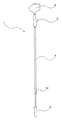
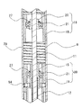
- FIG. 1 is a perspective view of the telescopic work machine 1 of the present invention
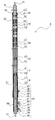
- FIG. 2 is a schematic cross-sectional view in the vertical direction of the collar part 4 of the telescopic work machine 1 in a contracted state
- FIG. It is a schematic sectional drawing of the vertical direction of the collar part 4 of the telescopic work machine 1, and the slide holder 34 which is the characteristics of the telescopic work machine 1 of this invention is shown to FIG. *
- the telescopic work machine 1 of the present invention includes a rotation drive unit 2 that generates a rotational force, a work unit 3 that is driven by the transmission of the rotational force, and the rotation drive unit that is located on the base end side. 2 and the working part 3 located on the front end side are connected, the rotational force is transmitted to the working part 3, and a retractable collar part 4 and an operation part 5 for operating the working part 3 are provided. It is possible to work at a high place using the working part 3 by extending and contracting the collar part 4. And the said telescopic working machine 1 uses the slide holder 34 as a means to fix in the state which expanded and contracted the said collar part 4 at the time of work.
- the rotation drive unit 2 incorporates, for example, a small engine that generates a rotational force
- the working unit 3 is, for example, a pruner having a reciprocating cutting blade, and is appropriately selected according to the work. be able to.
- the operation unit 5 is for operating the telescopic work machine 1 and is provided with a structure for performing operations such as turning on and off the rotation drive unit 2.
- the flange 4 is connected to the rotational drive unit 2 and is connected to the tubular proximal end tube 6 to which the operation unit 5 is attached, and the proximal end tube 6 in the axial direction.
- a telescopic tube body 7, and a shaft body 8 that extends in the axial direction in the proximal end tube 6 and the tubular body 7, and can be expanded and contracted in the axial direction in accordance with the expansion and contraction of the tubular body 7, As the tube body 7 and the shaft body 8 expand and contract in cooperation, the flange 4 has a structure that can expand and contract.
- the tubular body 7 is composed of a base end side outer tube 9 and a distal end side inner tube 10, and the inner diameter of the outer tube 9 is larger than the outer diameter of the inner tube 10. It is inserted into the outer tube 10 and is arranged so as to be movable in the outer tube 10 in the axial direction of the flange 4.
- the inner diameter of the inner tube 9 is 24 mm, for example, and the length is 1425 mm.
- the outer diameter of the outer tube 9 is, for example, 35 mm and the length is 1694 mm.
- the proximal end tube 6 is fixed to the proximal end of the outer tube 7 using a pipe joint 26.
- the proximal end side of the inner tube 10 is open, and the distal end side is closed by a lid having a hole into which the distal end of the shaft body 8 is inserted and protruded.
- the shaft body 8 includes a drive shaft 11 having a circular cross section disposed in the outer tube 9 and a pipe shaft 12 having an annular cross section disposed in the inner tube 10.
- the structure of the shaft 8 is not limited to the structure described here, and other structures are possible.
- the drive shaft 11 is rotatably held in the outer tube 9 by a plurality of bearings 18 disposed in the outer tube 9, and a proximal end side passes through the proximal tube 6 and drives the drive shaft 11. A portion connected to the portion 2 protrudes from the proximal end tube 6.
- the pipe shaft 12 is disposed in the inner tube 10 so as to be rotatable with respect to the inner tube 10 and not movable in the axial direction, and a tip portion projects from the inner tube 10.
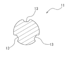
- three grooves 13 are formed in a spiral shape on the surface of the drive shaft 11.
- the drive shaft 11 is formed by twisting the bar steel after forming three rows of grooves 13 straight in the axial direction at equal intervals on the surface of the straight bar steel.
- the outer diameter of the drive shaft 11 is set to a small diameter of, for example, 6.5 mm
- a process of cutting the coiled steel bar into a predetermined length after stretching the steel bar is performed.
- simply stretching a coiled round steel bar does not make it straight, so a twisting process is required to obtain a straight steel bar.
- the spiral groove 13 in the drive shaft 11 by using a method of spiraling the linear groove by using such twisting process, the straight drive shaft 11 can be obtained. It is possible to eliminate vibration due to vibration during rotation.
- a spline-processed connecting portion 14 is fixed to the end of the drive shaft 11 on the base end side by friction welding, and the connecting portion 14 protrudes from the base end tube 6 so that the rotation driving portion 2 is connected. Are connected by spline fitting.
- the spline processing applied to the connecting portion 14 can be spline-fitted with a general rotation drive unit 2, and various types of rotation drive units 2 can be attached. In addition to spline processing, it is also possible to process into a prismatic shape and fit into the rotary drive unit 2 and fix.
- a connecting pipe 15 to which the drive shaft 11 is inserted and connected is fixed to an end portion on the proximal end side of the pipe shaft 12, and spline processing is performed on an end portion on the distal end side.
- the connecting part 17 to which is applied is fixed.
- the connecting portion 17 protrudes from the end of the inner tube 10 on the probe end side, and the working portion 3 is connected by spline fitting.
- the spline processing applied to the connecting portion 17 can be splined with a general working portion 3, and various types of working portions 3 can be attached. In addition to spline processing, it is also possible to process into a prismatic shape and fit into the working part 3 and fix.
- a step is formed between a large diameter portion having an inner diameter matching the outer diameter of the pipe shaft 12 and a small diameter portion having an inner diameter matching the outer diameter of the drive shaft 11.
- the outer surface has a stepped shape. An end portion on the proximal end side of the pipe shaft 12 is inserted into the large diameter portion, and is fitted and fixed.
- three spiral convex portions 16 are formed at equal intervals on the inner surface of the small-diameter portion of the connecting pipe 15, and along the grooves 13 of the drive shaft 11, Each convex portion 16 on the inner surface of the connecting tube 15 is movable.
- the drive shaft 11 is inserted into the connecting pipe 15 fixed to the pipe shaft 12 from the front end side.
- the convex portion 16 of the connecting pipe 15 is located in the groove 13 of the drive shaft 11, so that the pipe shaft 12 is expanded when the flange portion 4 is expanded and contracted.
- the convex portion 16 moves in the groove 13, so that the pipe shaft 12 can move in the axial direction along the outer surface of the drive shaft 11 while rotating.
- the drive shaft 11 is rotated by the rotary drive unit 2 in order to operate the working unit 3 with the pipe shaft 12 fixed without moving, the convex portion 16 and the groove 13 are engaged. In order to match, the rotation of the drive shaft 11 is transmitted to the pipe shaft 12, and the pipe shaft 12 also rotates.
- connection pipe 15 allows the pipe shaft 12 to move in the axial direction with respect to the drive shaft 11, and transmits the rotation of the drive shaft 11 to the pipe shaft 12.
- the shaft 11 and the pipe shaft 12 are connected.
- the shaft body 8 can be expanded and contracted, and the rotational force of the drive unit 2 is transmitted to the pipe shaft 12 via the drive shaft 11 and then transmitted to the working unit 3 to be worked unit 3. Is driven.
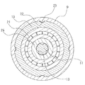
- the bearing 18 includes a substantially cylindrical bush holder 19, a substantially cylindrical drive bush 20 disposed in the bush holder 19, and an inner surface of the bush holder 19 and the drive bush 20.
- the drive bush 20 is configured to be rotatable with respect to the bush holder 19.
- the ball bearing 21 is disposed between the outer surface and the ball bearing 21.
- the inner surface of the outer tube 9 is formed with four convex portions 23 extending straight in the axial direction.
- the bush holder 19 has the convex portion 23 in the groove 22.
- the bush holder 19 is disposed in the outer tube 9 so as to be positioned so as to be movable in the axial direction with respect to the outer tube 9 and non-rotatable. Has been.
- each protrusion 24 extends along each groove 13 of the drive shaft 11. It is movable.
- the drive bush 20 moves while rotating when moving in the axial direction with respect to the drive shaft 11, and rotates together with the drive shaft 11 when the drive shaft 11 rotates.
- the bearing 18 having such a structure, the drive shaft 11 is disposed to be rotatable at the center of the outer tube 9, and the bearing 18 is disposed to be movable in the axial direction within the outer tube 9. .
- the drive shaft 11 is rotatably held in the outer tube 9 by the bearing 18, and the drive shaft 11 is connected to the outer end of the outer tube 9 at the base end side. It is arranged so as to be rotatable with respect to the tube 9 and not movable in the axial direction.
- a fixed bearing 28 using the bush holder 19 and the ball bearing 21 of the bearing 18 is used.
- the fixed bearing 28 includes the bush holder 19, the ball bearing 21, and a bush 25 in which a through hole is formed.
- the bush holder 19 is fixed to the proximal end of the outer tube 9 using a tapping screw 52.
- the bush 25 is partially fixed to the drive shaft 11 from the drive bush 20.
- the bush 25 is moved to a predetermined position of the drive shaft 11 and fixed to the drive shaft 11 using a hexagon socket set screw 53.
- the drive shaft 11 to which the bush 25 is fixed is inserted into the outer tube 9, the bush 25 is disposed at a position facing the bush holder 19 fixed to the outer tube 9, and the bush 25 and the bush After the ball bearing 21 is disposed between the holder 19 and the holder 19, the ball bearing 21 is fixed using a snap ring 27.
- the bush 25 is held rotatably with respect to the bush holder 19. Accordingly, the drive shaft 11 is disposed at the proximal end of the outer tube 9 so as to be rotatable with respect to the outer tube 9 and not movable in the axial direction.
- the reason why the bush holder 19 is used for the fixed bearing 28 is to reduce the cost by sharing parts. Therefore, it is possible to use other dedicated parts.
- bearings 18 are arranged in the outer tube 9, between the bearings 18, between the most proximal bearing 18 and the fixed bearing 28, and the most distal bearing 18.
- a spring 29 is arranged between the proximal end of the inner tube 10.
- the bearings 18 are arranged in the outer tube 9 at equal intervals by the spring 29, and the intervals change according to the expansion and contraction of the flange portion 4, but the intervals between the bearings 18 are always kept the same. Therefore, the bearings 18 are arranged at equal intervals, and the drive shaft 11 is held at a constant interval, so that vibration when the drive shaft 11 rotates can be suppressed.
- the number of the bearings 18 is appropriately determined according to the length of the drive shaft 11.
- the maximum rotational speed of the drive shaft 11 is 10000 rpm or more. Therefore, when the outer diameter is as thin as the drive shaft 11 having a diameter of 6.5 mm, driving between the bearings 18 increases the distance between the bearings 18. Since the shaft 11 bends, there is a problem that a jump rope phenomenon occurs and a large vibration occurs. Therefore, it is necessary to narrow the interval between the bearings 18. However, if the number of the bearings 18 is increased too much, the cost increases and the amount of expansion and contraction of the flange portion 4 decreases due to the increase in the number of bearings 18 and springs 29. The problem arises.
- the pipe shaft 12 is provided Is provided with a stopper 30.
- the stopper 30 includes a bush holder 19, a ball bearing 21, and the connecting pipe 15.
- the bush holder 19 is fixed by a blind rivet 54 with the end on the proximal end side of the inner tube 10 inserted.
- the pipe shaft 12 is arranged in the inner tube 10 so that the connecting tube 15 fixed to the proximal end of the pipe shaft 12 faces the bush holder 19 fixed to the inner tube 10. Then, the ball bearing 21 is press-fitted between the bush holder 19 and the connecting pipe 15 and fixed with a snap ring 27.
- the connecting pipe 15 is held rotatably with respect to the bush holder 19.
- the pipe shaft 12 is disposed at the proximal end of the inner tube 10 so as to be rotatable relative to the inner tube 10 and not movable in the axial direction.
- bearings 31 are fixed in the inner pipe 10 at equal intervals in the axial direction, and the pipe shaft 12 is rotatably held in the inner pipe 10 by the bearings 31.
- the bearing 31 includes a cylindrical bush holder 32 and a metal bush 33 press-fitted into the inner surface of the bush holder 32.
- the said pipe shaft 12 is inserted in the said metal bush 33, and, thereby, the said pipe shaft 12 is rotatably hold
- the inner pipe 10 in which the pipe shaft 12 is rotatably arranged in this way is arranged so as to be movable in the axial direction in the outer pipe 9 and is fixed to an end portion on the proximal end side of the inner pipe 10. Further, the spring 29 is disposed between the bush holder 19 and the most distal end bearing 18 disposed in the outer tube 9.
- a slide holder 34 having a function of fixing the inner tube 10 so as not to move with respect to the outer tube 9 and a function of releasing the fixing are disposed at the proximal end of the outer tube 9.
- the slide holder 34 includes a large-diameter portion 35 into which the outer tube 9 is inserted, and a small-diameter portion 36 into which the inner tube 10 protruding from the outer tube 9 is inserted,
- the cylindrical shape has a step at the boundary between the large diameter portion 35 and the small diameter portion 36.
- the outer tube 9 is inserted through the opening of the large-diameter portion 35 and is fixed so as not to move.
- the inner tube 10 protruding from the outer tube 9 is inserted into the small-diameter portion 36, and the small-diameter portion 36 is inserted.
- the outer tube 10 protrudes from the opening of the portion 36.
- a first slit 37 parallel to the axial direction and a second slit 38 orthogonal to the first slit 37 are formed.
- the first slit 37 extends from the opening of the small-diameter portion 36 to the vicinity of the step, and its width is slightly narrower from the opening side toward the step side, but gradually narrows.
- the second slit 38 is formed in a state of cutting a half circumference of the cylindrical small-diameter portion 36 in the vicinity of the center in the axial direction of the small-diameter portion 36. And the edge part of the said 1st slit 37 and the said 2nd slit 38 becomes a rib shape which protruded a little from the surface of the said small diameter part 36. As shown in FIG.
- first protrusions 39 and second protrusions 41 facing each other across the first slit 37, respectively, across the second slit 38.
- a through hole 40 is formed in the first protrusion 39, and a screw hole 42 is formed in the second protrusion 41.
- a bolt 43 having a knob 44 formed at the end is inserted from the through hole 40, and the tip end side of the bolt 43 protruding from the through hole 40 is screwed into the screw hole 42.
- the bolt 43 is rotated using two protruding portions of the knob 44 and is tightened or loosened. At this time, the bolt 43 is simply rotated and engaged with the screw in the through hole 40. In other words, only the screw hole 42 is engaged with the screw.
- a nylon sleeve 56 can be disposed between the inner surface of the small diameter portion 36 and the inner tube 10.
- the nylon sleeve 56 is used to increase the degree of adhesion when the inner tube 10 is fastened and fixed by the small diameter portion 36.
- a third slit 45 parallel to the axial direction is formed in the large diameter portion 35 of the slide holder 34, as shown in FIG. 13 (b), a third slit 45 parallel to the axial direction is formed.
- the third slit 45 extends from the opening of the large-diameter portion 35 to the vicinity of the center in the axial direction, and its width is slightly narrower from the opening side but gradually narrows.
- the edge portion of the third slit 45 has a rib shape protruding slightly from the surface of the large diameter portion 35.
- a third projecting portion 46 and a fourth projecting portion 48 that are opposed to each other with the third slit 45 interposed therebetween are provided on the surface of the large diameter portion 35.
- a through hole 47 is formed in the third protrusion 46, and a screw hole 49 is formed in the fourth protrusion 48.
- the bolt 50 is inserted from the through hole 47, and the front end side of the bolt 50 protruding from the through hole 47 is screw-engaged with the screw hole 49.
- the fourth projecting portion 47 approaches each other, the width of the third slit 45 is reduced, the large diameter portion 35 is reduced in diameter, and the outer peripheral surface of the outer tube 9 is tightened. Is fixed to the slide holder 34. Further, the large diameter portion 35 fixes the outer tube 9 using a fixing bolt 55.
- the means for fixing the outer tube 9 is not limited to such a form, and other fixing means can be used.
- the outer tube 9 is fixed to the slide holder 34
- the inner tube 10 is fixed by the slide holder 34 during operation, and the knob 4
- the inner tube 10 can be unlocked by operating 44. A function for fixing the inner tube 10 and a function for releasing the fixing will be described.
- the bolt 43 is rotated using the knob 44 in a direction in which the bolt 43 is tightened in the screw hole 42 of the second protrusion 41. Then, a force acts on the first projecting portion 39 and the second projecting portion 41 in a direction approaching each other, and the small-diameter portion 36 is deformed so that the width of the first slit 37 is narrowed so that the diameter becomes small. Become. As a result, the outer peripheral surface of the inner tube 10 is tightened by the small diameter portion 36 so that the inner tube 10 is fixed and cannot move.
- the small-diameter portion 36 is tightened by using two bolts 43, the small-diameter portion 36 of the slide holder 34 is obtained by applying a force so that the width of the first slit 37 becomes narrow at two locations. Since the inner tube 10 is deformed so that its diameter is reduced over almost the entire length, the range in which the inner tube 10 can be tightened is widened, and the strength for fixing the inner tube 10 is greatly increased as compared with the prior art. By providing the nylon sleeve 56, the degree of adhesion between the inner surface of the small diameter portion 36 and the surface of the inner tube 10 is increased, and the strength for fixing the inner tube 10 can be further increased.
- the bolts 43 When rotating the two bolts 43 in the tightening direction, the bolts 43 are tightened one by one. At this time, since the small-diameter portion 36 is partially divided into two parts by providing the second slit 38, the divided parts are separately separated by tightening the bolts 43. Even if it is deformed, since the influence of the deformation on each other is small, the small diameter portion 36 can fix the inner tube 10 more reliably. Further, since the knob 43 is provided on the bolt 43, the bolt 43 can be easily rotated and tightened without using a tool or the like.
- the bolt 43 is rotated in the loosening direction with respect to the screw hole 42 of the second protrusion 41 using the knob 44. Then, a force acts on the first projecting portion 39 and the second projecting portion 41 in a direction away from each other, and the small-diameter portion 36 is deformed to increase the diameter so that the width of the first slit 37 is widened. .
- the state in which the outer peripheral surface of the inner tube 10 is tightened by the small diameter portion 36 is canceled, and the inner tube 10 is released from being fixed and can move. In this way, the inner tube 10 can be easily fixed and released by the slide holder 34.
- a cushion tube 51 is disposed on the outer surface of the inner tube 10 between the bush holder 19 of the stopper 30 and the stepped portion of the inner surface of the slide holder 34.
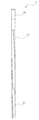
- FIG. 3 is a longitudinal sectional view of the telescopic work machine 1 in a state where the collar portion 4 is most extended.
- the bearings 18 are arranged at equal intervals with the springs 29 being most spaced apart, and the cushion tube 51 is a bush holder of the stopper 30. 19, the inner tube 10 protrudes most from the outer tube 9 by tightening the slide holder 34 with the two bolts 43 in this state. It is firmly fixed in the state.
- the state where the inner tube 10 is moved most into the outer tube 9 is the state shown in FIG. At this time, the drive shaft 11 is inserted into the pipe shaft 12 as far as possible.
- the spring 29 is contracted, and the bearings 18 are arranged at the narrowest intervals. In such a state, a force is applied to move the inner tube 10 toward the distal end side by the spring 29. Therefore, by tightening the bolt 43 by the knob 44 of the slide holder 34, The inner tube 10 is sandwiched and fixed by the small diameter portion 36 of the slide holder 34, thereby firmly fixing the inner tube 10 to the outer tube 9.
- the inner tube 10 is fixed by the slide holder 34 in the middle of the contraction, so that the collar portion 4 can be fixed and used with a predetermined length.
- the part 4 can be fixed in various lengths.
- the operation for extending the collar 4 will be described. 2, the bolt 43 is loosened by the knob 44 of the slide holder 34. Then, the inner tube 9 is released from being fixed, and the inner tube 9 can be moved in a direction protruding from the outer tube 10. At this time, the inner tube 10 can be easily moved because the force is applied in the direction in which the inner tube 10 protrudes from the outer tube 9 by the elastic force of the spring 29.
- the pipe shaft 12 also moves in the axial direction following the movement of the inner tube 10. As the pipe shaft 12 moves, the pipe 15 moves while rotating with respect to the drive shaft 11 by rotating while the connecting pipe 15 moves in the axial direction. The inner pipe 10 moves without being rotated by the ball bearing 21 of the stopper 30 and the metal bush 33 of the bearing 31.
- the telescopic work machine 1 can easily fix and release the inner tube 10 by operating the knob 33 of the slide holder 34, and the unlocked work machine 1 can be released in a state where the fixing is released.
- the eaves part 4 can be easily expanded and contracted and fixed.
- the telescopic work machine 1 can be used safely with the telescopic work machine 1 securely fixed.
- the rotational force of the rotation drive unit 2 is transmitted to the drive shaft 11 via the connection unit 14 that is spline-fitted with the rotation drive unit 2.
- the drive shaft 11 to which the rotational force is transmitted rotates in the outer tube 9. At this time, since the drive shaft 11 is rotatably held by the bearing 18 in the outer tube 9, the outer tube 9 does not rotate.
- the pipe shaft 12 When the drive shaft 11 rotates, the pipe shaft 12 also rotates through the connecting pipe 15 in which the drive shaft 11 is inserted.
- the convex portion 16 provided on the inner surface of the small diameter portion of the connecting pipe 15 is positioned in the groove 13 of the drive shaft 11, when the drive shaft 11 rotates, the groove 13 and the convex portion 16 become circular. Abutting in the circumferential direction, the rotation of the drive shaft 11 is transmitted to the connecting pipe 15. Thereby, when the drive shaft 11 rotates, the pipe shaft 12 also rotates.
- the connecting pipe 15 When the pipe shaft 12 is rotating, the connecting pipe 15 is rotatably held by the ball bearing 21 of the stopper 30 and the metal bush 33 of the bearing 31 in the inner pipe 10 of the pipe shaft 12. As a result, the inner tube 10 does not rotate.
- the telescopic work machine 1 uses the drive shaft 11 provided with a plurality of spiral grooves 13 to realize a shaft body 8 that is thinner and lighter than the conventional one. Can also be made thinner.
- the conventional working machine has a shaft having a diameter of 12 mm and an outer tube having a diameter of 47 mm.
- the drive shaft 11 is 6.5 mm and the outer tube 9 is 35 mm.
- the conventional working machine weighed 3.7 kg, so that the telescopic working machine 1 of the present invention can be reduced to 2.6 kg. For this reason, the hook 4 is easily gripped even by a small hand.
- the telescopic work machine 1 that is lighter and easier to handle than the conventional one is provided. It became possible.
- the drive shaft 11 is formed by twisting the bar steel after forming three rows of grooves 13 straight on the surface of the straight bar steel in the axial direction. Even if a long and thin drive shaft is used, such as a drive shaft 11 having a length of 6.5 mm and a length of 2043 mm, the drive shaft 11 can be formed straight and can be rotated without causing vibration. Therefore, the telescopic work machine 1 capable of transmitting the rotational force more stably can be realized.
- the telescopic work machine 1 of the present invention can fix the collar 3 easily and reliably, and can ensure safety during work.
- the slide holder 61 includes a large diameter portion 62 into which the outer tube 9 is inserted and a small diameter portion 63 into which the inner tube 10 protruding from the outer tube 9 is inserted.
- the cylindrical shape has a step at the boundary between 62 and the small diameter portion 63.
- the outer tube 9 is inserted through the opening of the large-diameter portion 62 and is fixed so as not to move.
- the small-diameter portion 63 is inserted with the inner tube 10 protruding from the outer tube 9, and the small-diameter The outer tube 10 protrudes from the opening of the portion 63.
- a first slit 64 parallel to the axial direction and a second slit 65 perpendicular to the first slit 64 are formed.
- the first slit 64 extends from the opening of the small-diameter portion 63 to the vicinity of the step, and its width is slightly narrower from the opening side toward the step side, but gradually narrows.
- the second slit 65 is formed in a state in which the cylindrical small-diameter portion 63 is cut in half the circumference in the vicinity of the center in the axial direction of the small-diameter portion 63.
- a nylon sleeve (not shown) can be disposed between the inner surface of the small diameter portion 63 and the inner tube 10 in the same manner as the slide holder 34.
- first protrusions 66 and second protrusions 68 On the surface of the small diameter portion 63, as shown in FIG. 15, there are two first protrusions 66 and second protrusions 68 that are opposed to each other with the first slit 64 interposed therebetween. Is provided. As shown by a broken line in FIG. 15, a through hole 67 is formed in the first protrusion 66, and a screw hole 69 is formed in the second protrusion 68. A bolt 70 having a gear-shaped knob 71 formed at the end is inserted from the through hole 67, and the front end side of the bolt 70 protruding from the through hole 67 is threadedly engaged with the screw hole 69.
- a gear 72 that meshes simultaneously with the teeth of the two knobs 71 is rotatably provided on the small diameter portion 63 using a gear bolt 83.
- the gear bolt 83 is arranged so that the small diameter portion 63 is sandwiched between the bolt 70 and the bolt 70.
- two knobs 79 are provided on the surface of the knob 71. When the knob 71 is rotated using the knob 79, the gear 72 is rotated, and the two knobs 71 are simultaneously the same. And the bolt 70 is tightened or loosened.
- a third slit 73 parallel to the axial direction is formed in the large diameter portion 62 of the slide holder 61.
- the third slit 73 extends from the opening of the large-diameter portion 62 to the vicinity of the center in the axial direction, and its width is slightly narrower from the opening side but gradually narrows.
- the edge portion of the third slit 73 has a rib shape protruding slightly from the surface of the large diameter portion 62.
- a third projecting portion 74 and a fourth projecting portion 76 that face each other with the third slit 73 interposed therebetween are provided on the surface of the large diameter portion 62.
- a through hole 75 is formed in the third protrusion 74, and a screw hole 77 is formed in the fourth protrusion 76.
- the third protrusion 74 and the fourth protrusion 76 approach each other by inserting the bolt 78 from the through hole 75 and screwing the bolt 78 by screwing the front end side with the screw hole 77.
- the third slit 73 is reduced in width, the large-diameter portion 62 is reduced in diameter and tightens the outer peripheral surface of the outer tube 9, and the outer tube 9 is fixed to the slide holder 61. Become. Further, the large diameter portion 62 fixes the outer tube 9 using a fixing bolt 82.
- the two bolts 70 are rotated simultaneously, so that the work time for fixing the inner tube 10 is shortened. Since the two bolts 70 are tightened simultaneously, the inner tube 10 can be evenly tightened by the small diameter portion 63.
- the gear 72 is rotated in the opposite direction, and the two bolts 70 are simultaneously rotated in a loosening direction with respect to the screw hole 69 of the second protrusion 68. Then, a force acts on the two pairs of the first projecting portion 66 and the second projecting portion 68 simultaneously in a direction away from each other, and the small diameter portion 63 is deformed so that the width of the first slit 64 is widened. The diameter increases. As a result, the state where the outer peripheral surface of the inner tube 10 is tightened by the small diameter portion 63 is eliminated, and the inner tube 10 is released from being fixed and can move. Thus, the slide holder 61 can easily and reliably fix and release the inner tube 10 by operating one gear 72.
Landscapes
- Life Sciences & Earth Sciences (AREA)
- Engineering & Computer Science (AREA)
- General Engineering & Computer Science (AREA)
- Biodiversity & Conservation Biology (AREA)
- Ecology (AREA)
- Forests & Forestry (AREA)
- Environmental Sciences (AREA)
- Mechanical Engineering (AREA)
- Harvester Elements (AREA)
- Mutual Connection Of Rods And Tubes (AREA)
- Harvesting Machines For Specific Crops (AREA)
- Scissors And Nippers (AREA)
Abstract
Le problème décrit par la présente invention est de fournir une machine de travail d'allongement/contraction, qui est apte à être fixée facilement et de manière fiable à une unité d'arbre. La solution selon l'invention porte sur une machine de travail d'allongement/contraction pourvue : d'une unité d'entraînement rotative ; d'une unité de travail ; d'une unité d'arbre qui relie l'unité d'entraînement rotative et l'unité de travail, transmet une force rotative à l'unité de travail, et peut s'allonger/se contracter, et d'un chariot support. L'unité d'arbre comporte un corps de tube qui peut s'allonger et se contracter, le corps de tube étant pourvu d'un tube externe et d'un tube interne qui peuvent se déplacer à l'intérieur du tube externe, le support coulissant comprend une section de grand diamètre fixée au tube externe et une section de petit diamètre dans lequel le tube interne est introduit, chacune des deux, d'une première saillie et d'une seconde saillie qui s'opposent l'une à l'autre en prenant en sandwich une première fente sont prévues à la surface de la section de petit diamètre prenant en sandwich une seconde fente, un boulon ayant un bouton au niveau de l'extrémité est inséré dans la première saillie et est fileté à vis à la deuxième saillie, le diamètre de la section à petit diamètre se rétrécit, se fixant sur le tube interne lorsque le boulon est serré au moyen du bouton, et le diamètre de la section à petit diamètre se dilate, libérant la fixation du tube interne lorsque le boulon est desserré au moyen du bouton.
Priority Applications (1)
| Application Number | Priority Date | Filing Date | Title |
|---|---|---|---|
| BR112016024346A BR112016024346A2 (pt) | 2014-07-11 | 2015-06-18 | máquina de podar extensível |
Applications Claiming Priority (2)
| Application Number | Priority Date | Filing Date | Title |
|---|---|---|---|
| JP2014143697A JP6341374B2 (ja) | 2014-07-11 | 2014-07-11 | 伸縮式作業機 |
| JP2014-143697 | 2014-07-11 |
Publications (1)
| Publication Number | Publication Date |
|---|---|
| WO2016006408A1 true WO2016006408A1 (fr) | 2016-01-14 |
Family
ID=55064048
Family Applications (1)
| Application Number | Title | Priority Date | Filing Date |
|---|---|---|---|
| PCT/JP2015/067616 Ceased WO2016006408A1 (fr) | 2014-07-11 | 2015-06-18 | Machine de travail d'allongement/contraction |
Country Status (3)
| Country | Link |
|---|---|
| JP (1) | JP6341374B2 (fr) |
| BR (1) | BR112016024346A2 (fr) |
| WO (1) | WO2016006408A1 (fr) |
Cited By (2)
| Publication number | Priority date | Publication date | Assignee | Title |
|---|---|---|---|---|
| CN107258353A (zh) * | 2017-06-23 | 2017-10-20 | 黄娉 | 一种用于园林绿化的植物修剪智能机器人 |
| CN112483629A (zh) * | 2019-09-12 | 2021-03-12 | 株式会社牧田 | 作业机械 |
Families Citing this family (2)
| Publication number | Priority date | Publication date | Assignee | Title |
|---|---|---|---|---|
| JP7219686B2 (ja) * | 2019-09-12 | 2023-02-08 | 株式会社マキタ | 支持棹および作業機 |
| JP2022099046A (ja) * | 2020-12-22 | 2022-07-04 | 京セラインダストリアルツールズ株式会社 | 電動工具 |
Citations (4)
| Publication number | Priority date | Publication date | Assignee | Title |
|---|---|---|---|---|
| JPS6074961U (ja) * | 1983-10-28 | 1985-05-25 | 富士通アイソテック株式会社 | ネジ回転機構 |
| JPS6413921U (fr) * | 1987-07-17 | 1989-01-24 | ||
| JPH0988923A (ja) * | 1995-09-22 | 1997-03-31 | Suritsuku Kk | 伸縮自在管のパイプクランプ装置 |
| JP2013240292A (ja) * | 2012-05-18 | 2013-12-05 | Taisei Monac Co Ltd | 伸縮式作業機 |
-
2014
- 2014-07-11 JP JP2014143697A patent/JP6341374B2/ja not_active Expired - Fee Related
-
2015
- 2015-06-18 WO PCT/JP2015/067616 patent/WO2016006408A1/fr not_active Ceased
- 2015-06-18 BR BR112016024346A patent/BR112016024346A2/pt not_active Application Discontinuation
Patent Citations (4)
| Publication number | Priority date | Publication date | Assignee | Title |
|---|---|---|---|---|
| JPS6074961U (ja) * | 1983-10-28 | 1985-05-25 | 富士通アイソテック株式会社 | ネジ回転機構 |
| JPS6413921U (fr) * | 1987-07-17 | 1989-01-24 | ||
| JPH0988923A (ja) * | 1995-09-22 | 1997-03-31 | Suritsuku Kk | 伸縮自在管のパイプクランプ装置 |
| JP2013240292A (ja) * | 2012-05-18 | 2013-12-05 | Taisei Monac Co Ltd | 伸縮式作業機 |
Cited By (3)
| Publication number | Priority date | Publication date | Assignee | Title |
|---|---|---|---|---|
| CN107258353A (zh) * | 2017-06-23 | 2017-10-20 | 黄娉 | 一种用于园林绿化的植物修剪智能机器人 |
| CN107258353B (zh) * | 2017-06-23 | 2020-09-25 | 福建欣龙美建设工程有限公司 | 一种用于园林绿化的植物修剪智能机器人 |
| CN112483629A (zh) * | 2019-09-12 | 2021-03-12 | 株式会社牧田 | 作业机械 |
Also Published As
| Publication number | Publication date |
|---|---|
| JP6341374B2 (ja) | 2018-06-13 |
| BR112016024346A2 (pt) | 2017-08-15 |
| JP2016019477A (ja) | 2016-02-04 |
Similar Documents
| Publication | Publication Date | Title |
|---|---|---|
| JP5995061B2 (ja) | 伸縮式作業機 | |
| JP6341374B2 (ja) | 伸縮式作業機 | |
| TWI438046B (zh) | Clamping device for hollow shafts | |
| WO2009101396A3 (fr) | Outils de coupe | |
| RU2009136697A (ru) | Стойкий к разрушению инструмент для сварки трением с перемешиванием | |
| CN104708574A (zh) | 旋转冲击工具 | |
| ES2623140T3 (es) | Dispositivo de acoplamiento para transmitir un movimiento de impulsión de una pieza de mano, que transmite vibraciones, a una herramienta para uso clínico, particularmente odontológica | |
| JP5184601B2 (ja) | 回転工具 | |
| JP2016078122A (ja) | 動力工具用の保持および解放機構 | |
| JP2016153136A (ja) | フレア工具 | |
| US20170291289A1 (en) | Connecting rod for an impact member of an impact tool | |
| JP2015212008A (ja) | ドリルチャック | |
| JP5737511B2 (ja) | 作業機 | |
| JP2018537625A (ja) | 取り外し可能なドリル部材を有する強固なセルフドリリングリベット | |
| US5439235A (en) | Apparatus for coupling concentric cylindrical members through the selective radial enlargement of one of the coupling components | |
| JP2021016920A (ja) | スリーブ引き抜き治具 | |
| KR102359592B1 (ko) | 절삭툴의 용이한 체결을 위한 홀더 | |
| KR20150076584A (ko) | 변속기의 동력인출샤프트 조립 및 탈거 장치 | |
| RU2699131C1 (ru) | Пробойник | |
| JP7227835B2 (ja) | ナット回し工具 | |
| EP3162506A1 (fr) | Outils de fixation avec manchons aimantés flottants | |
| JP2009082028A (ja) | 作業機 | |
| US1038881A (en) | Pipe-reamer. | |
| US20200139530A1 (en) | Rotating grip for a pneumatic tool | |
| EP4049792B1 (fr) | Outil d'aide à la rotation et outil de rotation fixé à l'aide |
Legal Events
| Date | Code | Title | Description |
|---|---|---|---|
| WWE | Wipo information: entry into national phase |
Ref document number: IDP00201507617 Country of ref document: ID |
|
| 121 | Ep: the epo has been informed by wipo that ep was designated in this application |
Ref document number: 15819641 Country of ref document: EP Kind code of ref document: A1 |
|
| NENP | Non-entry into the national phase |
Ref country code: DE |
|
| 122 | Ep: pct application non-entry in european phase |
Ref document number: 15819641 Country of ref document: EP Kind code of ref document: A1 |