WO2016006528A1 - Dispositif de positionnement - Google Patents
Dispositif de positionnement Download PDFInfo
- Publication number
- WO2016006528A1 WO2016006528A1 PCT/JP2015/069128 JP2015069128W WO2016006528A1 WO 2016006528 A1 WO2016006528 A1 WO 2016006528A1 JP 2015069128 W JP2015069128 W JP 2015069128W WO 2016006528 A1 WO2016006528 A1 WO 2016006528A1
- Authority
- WO
- WIPO (PCT)
- Prior art keywords
- nut
- inner ring
- stator
- preload
- outer ring
- Prior art date
- Legal status (The legal status is an assumption and is not a legal conclusion. Google has not performed a legal analysis and makes no representation as to the accuracy of the status listed.)
- Ceased
Links
Images

Classifications
-
- F—MECHANICAL ENGINEERING; LIGHTING; HEATING; WEAPONS; BLASTING
- F16—ENGINEERING ELEMENTS AND UNITS; GENERAL MEASURES FOR PRODUCING AND MAINTAINING EFFECTIVE FUNCTIONING OF MACHINES OR INSTALLATIONS; THERMAL INSULATION IN GENERAL
- F16C—SHAFTS; FLEXIBLE SHAFTS; ELEMENTS OR CRANKSHAFT MECHANISMS; ROTARY BODIES OTHER THAN GEARING ELEMENTS; BEARINGS
- F16C19/00—Bearings with rolling contact, for exclusively rotary movement
- F16C19/22—Bearings with rolling contact, for exclusively rotary movement with bearing rollers essentially of the same size in one or more circular rows, e.g. needle bearings
- F16C19/34—Bearings with rolling contact, for exclusively rotary movement with bearing rollers essentially of the same size in one or more circular rows, e.g. needle bearings for both radial and axial load
- F16C19/36—Bearings with rolling contact, for exclusively rotary movement with bearing rollers essentially of the same size in one or more circular rows, e.g. needle bearings for both radial and axial load with a single row of rollers
- F16C19/361—Bearings with rolling contact, for exclusively rotary movement with bearing rollers essentially of the same size in one or more circular rows, e.g. needle bearings for both radial and axial load with a single row of rollers with cylindrical rollers
- F16C19/362—Bearings with rolling contact, for exclusively rotary movement with bearing rollers essentially of the same size in one or more circular rows, e.g. needle bearings for both radial and axial load with a single row of rollers with cylindrical rollers the rollers being crossed within the single row
Definitions
- the present invention converts the relative rotational motion of the nut with respect to the screw shaft into the relative linear motion of the nut with respect to the screw shaft, and when the nut stops at a target position with respect to the screw shaft,
- the present invention relates to a positioning device that can be held at the position.
- This type of positioning device is used for the purpose of linearly moving one of two bodies of a robot, machine tool, etc. relative to the other.
- One of the screw shaft or nut is fixed to one of the two bodies, and the other of the screw shaft or nut is fixed to the other.
- the screw shaft and the nut are a slide screw or a ball screw (hereinafter collectively referred to as “feed screw”).
- the positioning device includes an actuator for rotating the nut.
- an ultrasonic motor has been conventionally employed (Patent Documents 1 and 2 below).
- the positioning device of Patent Document 2 using the composite vibrator type stator can increase the output and can rotate at a low speed.
- the pre-pressure that presses the stator to the output side becomes the braking force, so that the nut can be kept at the target position.
- the composite vibrator type stator it is not necessary to incorporate a reduction gear or an electromagnetic brake, and a positioning device having a simple structure can be obtained.
- the positioning device of Patent Document 2 since the positioning device of Patent Document 2 has a stator arranged outside the bearing that supports the rotor portion in the radial direction, the bearing is not easily affected by wear powder from the ultrasonic motor, and prevents damage to the bearing. Is also advantageous.
- the positioning device of Patent Document 2 accommodates a stator, a nut, and the like inside a case, directly drives the nut with the stator, and uses a bearing, an annular plate, and a fixing bolt for supporting the joint of the stator.
- the structure is connected to the end face of the case.
- a problem to be solved by the present invention is to provide a positioning device that can easily cope with a change of a feed screw driven by a composite vibrator type stator.
- the present invention converts the relative rotational movement of the nut with respect to the screw shaft into the relative linear motion of the nut with respect to the screw shaft, and the nut is intended for the screw shaft.
- a rolling bearing having an inner ring connected to the nut, an outer ring surrounding the inner ring, and a rolling element that rolls between the inner ring and the outer ring, and A configuration including a composite vibrator type stator that is connected to an outer ring and applies a driving force to the nut via the inner ring is adopted.
- the stator and the nut are connected via the rolling bearing. For this reason, the driving force of the stator can be applied to the nut via the inner ring. That is, the input path between the inner ring and the stator is independent of the output path between the inner ring and the nut. For this reason, it is possible to change a lead screw, without changing an input path. Further, if there is no need to change the input path, there is no change in the positional relationship between the inner ring and the stator, and no change is required in the connection structure between the outer ring and the stator that constitute the rolling bearing together with the inner ring.
- the output side component refers to a component that is rotated integrally with the inner ring by a driving force generated by the stator.
- the encoder further includes an encoder coupled to the inner ring for converting the rotational motion of the inner ring into a physical signal, and a sensor circuit coupled to the outer ring for converting the physical signal into an output signal.
- an encoder coupled to the inner ring for converting the rotational motion of the inner ring into a physical signal
- a sensor circuit coupled to the outer ring for converting the physical signal into an output signal.
- the rolling bearing is preferably a cross roller bearing.
- the cross roller bearing is a bearing in which cylindrical rollers are assembled in an orthogonal arrangement between the inner and outer rings, it has a feature that it can be made compact while receiving loads in various directions at the same time. Therefore, in this invention, when a cross roller bearing is adopted as the rolling bearing, the size of the rolling bearing can be suppressed while accommodating a complicated load, and the positioning device can be made compact.
- the nut and the screw shaft are provided as a slide screw or a ball screw. By changing the output side part and the screw shaft, it is possible to switch the feed screw type without changing the rolling bearing and the stator.
- a mounting bolt screwed into the inner ring is further provided, and the nut is connected to the inner ring by fastening using the mounting bolt. If the nut is connected to the inner ring by bolt fastening in this way, when changing the output side part, the output side part having different specifications can be connected to the inner ring using the female thread portion of the inner ring.
- the nut and the spacer can be connected to the inner ring by the fastening.
- the preload nut that abuts against the outer ring from one side in the axial direction, the preload bolt that is screwed into the preload nut, the stator and the preload bolt inside the preload nut are axially moved in the axial direction.
- a preload spring that is compressed into a circumferential direction, a locking piece that stops the stator in the circumferential direction and supports the stator in the radial direction, and a fixing bolt that is screwed into the outer ring, and the preloading nut and the locking piece Is preferably fastened to the outer ring by the fixing bolt.
- the preloading nut and the locking piece are fastened to the outer ring with a fixing bolt, the axial position of the stator is determined in a predetermined manner via the preloading spring and the preloading bolt, and the radial position of the stator is also set by the locking piece. It can be determined in advance. In other words, the stator can be connected to the outer ring only by the detent and preload structure essential for the composite vibrator type stator.
- the present invention by adopting the above configuration, it is possible to cope with the change of the feed screw by changing only the output side component connected to the inner ring. Therefore, it is possible to provide a positioning device that can easily cope with the change of the feed screw. .
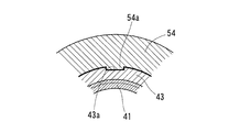
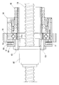
- FIG. 1 is a longitudinal front view showing the overall configuration of the positioning device according to the first embodiment. Partial sectional view taken along line II-II in FIG. Longitudinal front view showing an example in which the lead screw in FIG. 1 is changed to a ball screw
- the positioning device includes a screw shaft 10, a nut 20, a rolling bearing 30, a composite vibrator type stator 40, a preload connecting means 50, and a rotation sensor 60.
- the screw shaft 10 and the nut 20 function as a feed screw that converts the relative rotational motion of the nut 20 with respect to the screw shaft 10 into the relative linear motion of the nut 20 with respect to the screw shaft 10.
- the direction along the central axis of the screw shaft 10 corresponds to the “axial direction”, and the direction perpendicular to the axial direction corresponds to the “radial direction”.
- the screw shaft 10 is a male threaded part in which a JIS-standard metric trapezoidal screw is formed on the outer periphery.
- the nut 20 is a female screw part in which a trapezoidal screw corresponding to the screw shaft 10 is formed on the inner periphery.
- the screw shaft 10 and the nut 20 are provided as slide screws that are directly screwed together with each other's trapezoidal screws.
- the rolling bearing 30 includes an inner ring 31 connected to the nut 20, an outer ring 32 surrounding the inner ring 31, and a plurality of rolling elements 33 that roll between the inner ring 31 and the outer ring 32.
- the rolling bearing 30 supports the nut 20 of the aforementioned slide screw in the radial direction and the axial direction.
- Rolling bearing 30 is a cross roller bearing. That is, the rolling element 33 consists of cylindrical rollers.
- the inner ring 31 and the outer ring 32 are each formed of an annular body that forms a V-groove-shaped track.
- the inner ring 31 and the outer ring 32 are arranged concentrically.
- the plurality of rolling elements 33 are interposed between the races of the inner ring 31 and the outer ring 32. These rolling elements 33 are arranged in different directions by 90 ° alternately in the circumferential direction.
- the rolling bearing 30 provided as a cross roller bearing incorporates rolling elements 33 made of cylindrical rollers in an orthogonal arrangement between the inner and outer rings 31 and 32, so that the axial load is improved by the excellent load performance of the cylindrical rollers. Since it is possible to simultaneously receive loads in various directions such as radial loads and moment loads, it is possible to achieve compactness. As a result, the positioning device can be made compact.
- the inner ring 31 is fitted in a first bearing seat 20a formed on the nut 20.
- the first bearing seat portion 20 a is formed on the outer periphery of the end portion on one axial side of the nut 20.
- a cage or a separator can be appropriately employed as means (not shown) for maintaining the circumferential interval of the rolling elements 33.
- the inner ring 31 and the outer ring 32 are composed of one annular part that forms the entire track. If there is no problem in rigidity, the inner ring 31 and the outer ring 32 may be appropriately changed to a split type ring that forms a track with a plurality of annular parts.
- the stator 40 applies only a rotational driving force to the rotor that is in direct contact with the stator 40 by combining axial vibration and circumferential vibration.
- the stator 40 is connected to the outer ring 32 by a connection preload means 50.
- the stator 40 includes a stator head 42, a node 43, a first piezoelectric element 44, a second piezoelectric element 45, and a stator bottom 46.
- the hollow bolt 41 is a hollow shaft-shaped male screw part that can be inserted through the screw shaft 10 in the axial direction.
- the hollow bolt 41 is disposed away from the inner ring 31 toward the one axial side.
- the stator head 42 protrudes from the hollow bolt 41 to the other side in the axial direction, and is pressed against the side surface of the inner ring 31 from one axial direction to the other axial direction at the protruding end. This pressing is realized by the preload connecting means 50.
- the joint 43 holds the first piezoelectric element 44 in the axial direction together with the stator head 42.
- the first piezoelectric element 44 vibrates in the axial direction.
- the node portion 43 holds the second piezoelectric element 45 in the axial direction together with the stator bottom 46.
- the stator bottom 46 prevents the second piezoelectric element 45 from coming off from the hollow bolt 41.
- the second piezoelectric element 45 vibrates in the circumferential direction.
- the first piezoelectric element 44 and the second piezoelectric element 45 are each connected to a power supply device (not shown) that generates a high-frequency current.
- a power supply device not shown
- the vibrations of the first piezoelectric element 44 and the second piezoelectric element 45 are combined and provided from the stator head 42 as a rotor. Only the rotational driving force is applied to the side surface of the inner ring 31.
- the stator 40 when the stator 40 is driven, the node 43 interposed between the first piezoelectric element 44 and the second piezoelectric element 45 becomes a node in the vibration mode.
- a stator 40 is generally called a bolted Langevin type composite vibrator.
- the first piezoelectric element 44 and the second piezoelectric element 45 are annular bodies surrounding the hollow bolt 41, respectively. Further, since the stator head 42, the joint 43, and the stator bottom 46 are female screw parts corresponding to the hollow bolt 41, they can be screwed onto the hollow bolt 41.
- the node 43 may be formed as a part of the hollow bolt 41. Further, another member such as a friction member may be interposed between the inner ring 31 and the stator 40 to drive the inner ring 31 indirectly.
- the preload connecting means 50 connects the stator 40 to the outer ring 32 and presses the stator 40 against the inner ring 31.
- the preload connecting means 50 includes a preload nut 51, a preload bolt 52, a preload spring 53, a locking piece 54, and a fixing bolt 55.
- the preload nut 51 is a female threaded part that abuts against the side surface of the outer ring 32 from one side in the axial direction toward the other side in the axial direction.
- the stator head 42 has a spring receiving portion 42 a whose outer diameter is partially enlarged inside the preload nut 51.
- the preload spring 53 is a coil spring that can be inserted into the annular space between the stator 40 and the preload nut 51.
- the preload bolt 52 is a male screw component corresponding to the preload nut 51.
- the preloading spring 53 is screwed into the preloading nut 51 and the preloading spring 53 is compressed from one axial side toward the other axial side.
- the preload spring 53 compressed in the axial direction by the stator 40 and the preload bolt 52 generates a preload that presses the stator 40 against the side surface of the inner ring 31 from one axial direction to the other axial direction.
- the preload acts as a braking force that stops the inner ring 31. If the compression amount of the preload spring 53 is adjusted by the screwing amount of the preload bolt 52, the preload (braking force) for pressing the stator 40 against the inner ring 31 can be adjusted.
- the fixing bolt 55 is a male screw component corresponding to the first female screw portion 32 a formed on the outer ring 32.
- the first female thread portion 32a is formed from one axial side to the other axial side.
- the preload nut 51 and the locking piece 54 are connected to the outer ring 32 by fastening through which the fixing bolt 55 is inserted from the one axial side to the other axial side and screwed into the first female screw portion 32a. In this connected state, the locking piece 54 stops the stator 40 in the circumferential direction and supports it in the radial direction.
- the locking piece 54 has a tip 54 a that protrudes in the radial direction toward the node 43.
- the node portion 43 has a distal end portion 54a and a latch receiving portion 43a that can be engaged with both sides in the circumferential direction.
- the latch receiving portion 43 a is formed in a groove shape along the axial direction.
- the outer peripheral portion of the node portion 43 other than the locking receiving portion 43a is arcuately overlapped with the inner peripheral portion of the locking piece 54 in the radial direction.
- the overlapping region, the locking receiving portion 43a, and the distal end portion 54a are present in the circumferential direction. Due to these overlapping regions, radial support of the stator 40 by the locking pieces 54 is realized.
- the driving force cannot be effectively applied to the inner ring 31 unless the stator 40 is prevented from rotating. For this reason, it is indispensable to prevent the stator 40 from rotating at the node 43 that is the node of the vibration mode in the stator 40.
- the axial position of the stator 40 is determined in a predetermined manner via the preloading spring 53 and the preloading bolt 52, and the locking piece 54
- the radial position of the stator 40 can also be predetermined.
- the stator 40 can be connected to the outer ring 32 with only the detent and preload structure essential for the stator 40.
- the fixing bolts 55 are provided at a plurality of locations in the circumferential direction.
- the stator 40 When the stator 40 is connected to the outer ring 32 by the preload connecting means 50 as described above, the stator 40 is placed on one side in the axial direction with the rolling bearing 30 as a boundary. In this state, the inner ring 31 and the hollow bolt 41 are disposed on the same central axis. Since the inner diameter of the bearing hole of the rolling bearing 30 matches the inner diameter of the hollow bolt 41, the outer diameter of the screw shaft 10 can be changed within the range of the inner diameter of the hollow bolt 41.
- the inner diameter of the bearing hole is the diameter of a cylindrical inner diameter surface formed in the inner ring 31.
- the inner diameter of the hollow bolt 41 is the diameter of the inner diameter surface formed in a cylindrical shape over the entire axial length of the hollow bolt 41.
- the rotation sensor 60 converts the rotational motion of the inner ring 31 into an output signal. Based on this output signal, voltage application control of the first piezoelectric element 44 and the second piezoelectric element 45 can be performed.
- the rotation sensor 60 includes an encoder 61, an encoder holder 62, a mounting bolt 63, a sensor circuit 64, a sensor holder 65, and a holder fixing bolt 66.
- the encoder 61 is a magnetic encoder having S poles and N poles alternately in the circumferential direction, and converts the rotational movement around the axis into a magnetic physical signal.
- the encoder 61 is fixed to the encoder holder 62.
- the encoder holder 62 is an annular part that prevents deformation of the encoder 61.
- the encoder holder 62 is formed with a first bolt through hole 62a penetrating in the axial direction.
- the inner ring 31 is formed with a female thread portion 31a from the other side in the axial direction toward one side in the axial direction.
- a second bolt through hole 20b penetrating in the axial direction is formed at the end of the nut 20 on the other side in the axial direction.
- the mounting bolt 63 is a male screw component corresponding to the female screw portion 31a.
- the nut 20 and the encoder holder 62 are fastened by passing the mounting bolt 63 through the first bolt through hole 62a and the second bolt through hole 20b from the other side in the axial direction toward the one side in the axial direction, and further screwed into the female thread portion 31a. 31 is connected.
- the encoder 61, the nut 20, and the inner ring 31 rotate together by driving the inner ring 31 with the stator 40.
- the mounting bolts 63 are provided at a plurality of locations in the circumferential direction.
- Sensor circuit 64 converts the magnetic physical signal described above into an electrical signal.
- the sensor circuit 64 has a magnetic sensor mounted on a circuit board.
- the circuit board is provided with appropriate circuit elements such as a signal processing circuit for adjusting the output of the magnetic sensor to a predetermined output signal, a power supply circuit, and a wiring connection terminal.
- the sensor circuit 64 is fixed to the sensor holder 65.
- the sensor holder 65 is an annular part that prevents deformation of the sensor circuit 64.
- the sensor holder 65 is formed with a second bearing seat 65 a that fits into the outer ring 32. By fitting the sensor holder 65 to the second bearing seat 65a from the other side in the axial direction toward one side in the axial direction, it is possible to temporarily determine the axial position and the radial position of the sensor holder 65 with respect to the outer ring 32. It has become.
- the sensor holder 65 is formed with an attachment hole 65b that can be used to attach this positioning device to other devices such as a transport device and a lathe.
- the preload coupling means 50 is set to an outer diameter equal to or smaller than the outer diameter of the outer ring 32 (the bearing outer diameter of the rolling bearing 30), and does not hinder the use of the mounting hole 65b.
- the sensor holder 65 is formed with a third bolt through hole 65c penetrating in the axial direction.
- the outer ring 32 is formed with a second female thread portion 32b from the other side in the axial direction toward one side in the axial direction. In a state where the outer ring 32 is fitted to the second bearing seat portion 65a, the third bolt through hole 65c and the second female screw portion 32b communicate in the axial direction.
- the holder fixing bolt 66 is a male screw component corresponding to the second female screw portion 32b.
- the sensor holder 65 is connected to the outer ring 32 by fastening in which the holder fixing bolt 66 is passed through the third bolt through hole 65c from the other side in the axial direction toward the one side in the axial direction and further screwed into the second female screw portion 32b.
- the sensor circuit 64 can convert the rotational motion of the inner ring 31 relative to the outer ring 32 into an output signal.
- the holder fixing bolts 66 are provided at a plurality of locations in the circumferential direction.
- the first female screw portion 32a and the second female screw portion 32b are illustrated as examples in which the outer ring 32 is processed into the inner wall surface of a hole penetrating in the axial direction. However, the first female screw portion 32a and the second female screw portion 32b can also be formed with different phases in the circumferential direction. .
- the encoder 61 and the sensor circuit 64 are connected to the corresponding inner ring 31 and outer ring 32 as described above, the encoder 61 and the sensor circuit 64 are arranged on the other side in the axial direction with the rolling bearing 30 as a boundary. In this arrangement state, the nut 20 and the rotation sensor 60 do not protrude from the inner ring 31 and the outer ring 32 to one side in the axial direction, and do not come into contact with the stator 40 or the preload connecting means 50.
- the encoder 61 and the sensor circuit 64 are connected to the corresponding inner ring 31 and outer ring 32 as described above, the encoder 61 that rotates integrally with the inner ring 31 converts the rotational motion of the inner ring 31 driven by the stator 40 into a physical signal.
- the sensor circuit 64 integrated with the outer ring 32 stationary with respect to the inner ring 31 can convert the physical signal into an output signal. Therefore, this positioning device controls the first piezoelectric element 44 and the second piezoelectric element 45 of the stator 40 based on the output signal, and can accurately feed the feed screw.
- the stator 40 when the stator 40 is connected to the outer ring 32 of the rolling bearing 30 by the preload connecting means 50 and the nut 20 is connected to the inner ring 31 by the mounting bolt 63, the stator 40 and the nut 20 are connected via the rolling bearing 30. . For this reason, the driving force of the stator 40 can be applied to the nut 20 via the inner ring 31. That is, the output path between the inner ring 31 and the nut 20 is constituted by the mounting bolt 63 and the fitting surface of the bearing seat 20a and the inner ring 31.
- the input path between the inner ring 31 and the stator 40 is constituted by the stator head 42 and the side surface on the one axial side of the inner ring 31 and is therefore independent of the aforementioned output path.
- the positioning device according to the first embodiment can change the feed screw (screw shaft 10, nut 20) by changing only the output side component connected to the inner ring 31 without changing the input path and the preload connecting means 50 described above. ).
- Fig. 3 shows an example in which the slide screw in Fig. 1 is changed to a ball screw with a different feed rate.
- the ball screw shown in FIG. 3 has a ball (not shown) interposed between the screw shaft 70 and the spiral groove of the nut 80 in a circulating manner.
- the ball screw having the structure disclosed in Patent Document 2 is adopted. Can do.
- the screw shaft 70 and the nut 80 are reduced in diameter.
- the rolling bearing 30, the stator 40, and the preload connecting means 50 are not changed from those in FIG.
- the output side parts having different specifications can be connected to the inner ring 31 by using the female thread portion 31a of the inner ring 31.
- the encoder holder 90 is a spacer interposed between the nut 80 and the inner ring 31.
- the encoder holder 90 is changed to a shape that can maintain the magnetic gap between the encoder 61 and the sensor circuit 64 as in FIG.
- the nut 80 and the encoder holder (spacer) 90 can be connected to the inner ring 31 by fastening by screwing the mounting bolt 63 into the female thread portion 31 a of the inner ring 31.
Landscapes
- Engineering & Computer Science (AREA)
- General Engineering & Computer Science (AREA)
- Mechanical Engineering (AREA)
- Rolling Contact Bearings (AREA)
- Transmission Devices (AREA)
- Mounting Of Bearings Or Others (AREA)
- Connection Of Motors, Electrical Generators, Mechanical Devices, And The Like (AREA)
- General Electrical Machinery Utilizing Piezoelectricity, Electrostriction Or Magnetostriction (AREA)
- Support Of The Bearing (AREA)
Abstract
L'invention fournit un dispositif de positionnement qui répond facilement aux modifications d'une vis d'avance entraînée par un stator type oscillateur composite. Des écrous (20, 80) sont couplés à une roue interne (31) d'un palier à roulement (30), et un stator (40) est couplé à une roue externe (32) du palier à roulement (30). Ainsi, il est possible de répondre aux modifications de vis d'avance (axe de rotation avec translation (10), écrou (20)) par modification uniquement d'un composant côté sortie tel que, par exemple, l'écrou (20) couplé à la roue interne (31).
Applications Claiming Priority (2)
| Application Number | Priority Date | Filing Date | Title |
|---|---|---|---|
| JP2014140530A JP6367025B2 (ja) | 2014-07-08 | 2014-07-08 | 位置決め装置 |
| JP2014-140530 | 2014-07-08 |
Publications (1)
| Publication Number | Publication Date |
|---|---|
| WO2016006528A1 true WO2016006528A1 (fr) | 2016-01-14 |
Family
ID=55064164
Family Applications (1)
| Application Number | Title | Priority Date | Filing Date |
|---|---|---|---|
| PCT/JP2015/069128 Ceased WO2016006528A1 (fr) | 2014-07-08 | 2015-07-02 | Dispositif de positionnement |
Country Status (2)
| Country | Link |
|---|---|
| JP (1) | JP6367025B2 (fr) |
| WO (1) | WO2016006528A1 (fr) |
Cited By (2)
| Publication number | Priority date | Publication date | Assignee | Title |
|---|---|---|---|---|
| CN115702295A (zh) * | 2020-07-24 | 2023-02-14 | 索尤若驱动有限及两合公司 | 用于制造减速器的方法和系统 |
| CN120777327A (zh) * | 2025-09-12 | 2025-10-14 | 苏州铁近机电科技股份有限公司 | 一种基于轴承传动的摩擦减速器 |
Citations (2)
| Publication number | Priority date | Publication date | Assignee | Title |
|---|---|---|---|---|
| JP2002310174A (ja) * | 2001-04-18 | 2002-10-23 | Nsk Ltd | モータ付き軸受 |
| WO2007088691A1 (fr) * | 2006-01-31 | 2007-08-09 | Thk Co., Ltd. | Dispositif d'entraînement de moteur électrique creux |
-
2014
- 2014-07-08 JP JP2014140530A patent/JP6367025B2/ja not_active Expired - Fee Related
-
2015
- 2015-07-02 WO PCT/JP2015/069128 patent/WO2016006528A1/fr not_active Ceased
Patent Citations (2)
| Publication number | Priority date | Publication date | Assignee | Title |
|---|---|---|---|---|
| JP2002310174A (ja) * | 2001-04-18 | 2002-10-23 | Nsk Ltd | モータ付き軸受 |
| WO2007088691A1 (fr) * | 2006-01-31 | 2007-08-09 | Thk Co., Ltd. | Dispositif d'entraînement de moteur électrique creux |
Cited By (2)
| Publication number | Priority date | Publication date | Assignee | Title |
|---|---|---|---|---|
| CN115702295A (zh) * | 2020-07-24 | 2023-02-14 | 索尤若驱动有限及两合公司 | 用于制造减速器的方法和系统 |
| CN120777327A (zh) * | 2025-09-12 | 2025-10-14 | 苏州铁近机电科技股份有限公司 | 一种基于轴承传动的摩擦减速器 |
Also Published As
| Publication number | Publication date |
|---|---|
| JP6367025B2 (ja) | 2018-08-01 |
| JP2016017570A (ja) | 2016-02-01 |
Similar Documents
| Publication | Publication Date | Title |
|---|---|---|
| US9528581B2 (en) | Motor driven linear actuator and electric motor thereof | |
| US8978497B2 (en) | Linear actuator with anti-rotation mechanism | |
| US9145949B2 (en) | Reducer of electric power steering apparatus | |
| CN107086722B (zh) | 带电动机的减速器 | |
| WO2016006545A1 (fr) | Dispositif d'entraînement de joint articulé | |
| CN106464113B (zh) | 直接驱动电动机、输送装置、检查装置以及机床 | |
| US10859143B2 (en) | Linear driving system | |
| JP2013075546A (ja) | 電動パワーステアリング装置 | |
| US10465776B2 (en) | Actuator with cross-roller bearing | |
| JP6367025B2 (ja) | 位置決め装置 | |
| US20200332870A1 (en) | Ball screw device and steering device | |
| JP6140413B2 (ja) | 回転電機 | |
| CN220147412U (zh) | 转向器和车辆 | |
| KR20170088167A (ko) | 랙구동형 동력 보조 조향장치 | |
| KR101490541B1 (ko) | 운동 장치 및 이동 장치 | |
| JP7222263B2 (ja) | 電動パワーステアリング装置 | |
| JP6019933B2 (ja) | 直動テーブル装置 | |
| JP2020172170A (ja) | 電動パワーステアリング装置 | |
| JP5273270B2 (ja) | 回転機構付軸方向微動機構およびそれを用いた位置決め装置 | |
| JP5041147B2 (ja) | 電動モータ | |
| JP5067487B2 (ja) | 位置決め装置 | |
| JP5041146B2 (ja) | 電動モータ | |
| US20230299636A1 (en) | Drive including an electric motor with a brake assembly | |
| JP4877603B2 (ja) | 電動モータ | |
| JP2007232129A (ja) | ボールねじ装置の芯合せ治具およびそれを用いた芯合せ方法 |
Legal Events
| Date | Code | Title | Description |
|---|---|---|---|
| 121 | Ep: the epo has been informed by wipo that ep was designated in this application |
Ref document number: 15819602 Country of ref document: EP Kind code of ref document: A1 |
|
| NENP | Non-entry into the national phase |
Ref country code: DE |
|
| 122 | Ep: pct application non-entry in european phase |
Ref document number: 15819602 Country of ref document: EP Kind code of ref document: A1 |