WO2016006596A1 - Dispositif d'usinage ultrasonique - Google Patents
Dispositif d'usinage ultrasonique Download PDFInfo
- Publication number
- WO2016006596A1 WO2016006596A1 PCT/JP2015/069493 JP2015069493W WO2016006596A1 WO 2016006596 A1 WO2016006596 A1 WO 2016006596A1 JP 2015069493 W JP2015069493 W JP 2015069493W WO 2016006596 A1 WO2016006596 A1 WO 2016006596A1
- Authority
- WO
- WIPO (PCT)
- Prior art keywords
- ultrasonic
- shaft
- ultrasonic transducer
- langevin type
- type ultrasonic
- Prior art date
- Legal status (The legal status is an assumption and is not a legal conclusion. Google has not performed a legal analysis and makes no representation as to the accuracy of the status listed.)
- Ceased
Links
Images
Classifications
-
- B—PERFORMING OPERATIONS; TRANSPORTING
- B06—GENERATING OR TRANSMITTING MECHANICAL VIBRATIONS IN GENERAL
- B06B—METHODS OR APPARATUS FOR GENERATING OR TRANSMITTING MECHANICAL VIBRATIONS OF INFRASONIC, SONIC, OR ULTRASONIC FREQUENCY, e.g. FOR PERFORMING MECHANICAL WORK IN GENERAL
- B06B1/00—Methods or apparatus for generating mechanical vibrations of infrasonic, sonic, or ultrasonic frequency
- B06B1/02—Methods or apparatus for generating mechanical vibrations of infrasonic, sonic, or ultrasonic frequency making use of electrical energy
- B06B1/06—Methods or apparatus for generating mechanical vibrations of infrasonic, sonic, or ultrasonic frequency making use of electrical energy operating with piezoelectric effect or with electrostriction
-
- B—PERFORMING OPERATIONS; TRANSPORTING
- B23—MACHINE TOOLS; METAL-WORKING NOT OTHERWISE PROVIDED FOR
- B23B—TURNING; BORING
- B23B1/00—Methods for turning or working essentially requiring the use of turning-machines; Use of auxiliary equipment in connection with such methods
-
- B—PERFORMING OPERATIONS; TRANSPORTING
- B23—MACHINE TOOLS; METAL-WORKING NOT OTHERWISE PROVIDED FOR
- B23B—TURNING; BORING
- B23B37/00—Boring by making use of vibrations of ultrasonic frequency
Definitions
- the present invention relates to an ultrasonic processing apparatus, and more particularly to an apparatus for performing various machining operations such as cutting, drilling, and grinding on a material to be processed by rotation of a processing tool provided with ultrasonic vibration.
- ultrasonic vibration While applying ultrasonic vibration to a processing tool (machining tool) such as a drill or milling tool mounted on a machining device, by rotating those processing tools, the material (workpiece) to be processed
- machining tool such as a drill or milling tool mounted on a machining device
- operations for performing various machining processes such as cutting, drilling, and grinding are usually named ultrasonic machining and are widely used as processing means for various materials.
- Various types of vibrators or vibrators that impart ultrasonic vibrations to machining tools used for machining are known, and among them, powerful ultrasonic vibrations can be applied to machining tools.
- Bolt-clamped Langevin type ultrasonic transducers are most commonly used.
- Bolt-clamped Langevin type ultrasonic transducers are configured by arranging a pair of rigid molded bodies called front mass and rear mass on both sides of a piezoelectric element equipped with electrodes, and tightening them together with bolts to unite them. It is the comprised ultrasonic transducer
- ultrasonic vibration longitudinal vibration
- the ultrasonic vibrator rotates at a high speed while being supported by a casing (rotary casing) that also rotates integrally, but leakage of ultrasonic vibration energy to the rotating casing is also likely to occur. Leakage of ultrasonic vibration also results in a decrease in processing accuracy and processing efficiency.
- Patent Document 1 The inventors of the present invention have been conducting research for the purpose of improving the ultrasonic processing apparatus as described above for many years. And the improvement structure of a powerful ultrasonic processing apparatus has already been invented, and the invention is disclosed in Patent Document 1.
- Patent Document 1 discloses a rotating casing that supports a vibration composite of a processing tool (eg, drill) and an ultrasonic vibrator with high stability and has vibration energy of ultrasonic vibration generated by the ultrasonic vibrator.
- a support structure has been disclosed that allows for the application of vibration energy to a machining tool with high efficiency by suppressing leakage to a low level.
- a flange is attached to an ultrasonic vibrator provided with a machining tool, and one side of the flange is formed on a separately prepared fixed body (rotary casing).
- a structure that engages and supports the contact surface by applying stress to the support surface (However, the flange of the ultrasonic vibrator is not joined to the flange support surface of the fixed body, and is in contact with the support surface of the fixed body.
- the flange of the ultrasonic vibrating body engaged and supported in this manner is structured so as to ultrasonically vibrate in the thickness direction of the flange when the ultrasonic vibrating body is in a vibrating state).
- the present inventor has repeatedly studied the support structure of the ultrasonic vibrator disclosed in Patent Document 1, aiming at the development of an ultrasonic processing apparatus with higher practicality.
- the ultrasonic processing apparatus using the support structure of the ultrasonic vibrator disclosed in Patent Document 1, ultrasonic waves to the support structure (rotary casing) that supports the ultrasonic vibrator on the side surface are provided. It was confirmed that leakage of vibration energy was significantly reduced.
- the suppression of the transmission of the transverse vibration of the ultrasonic vibration to the machining tool may be insufficient.
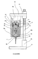
- the support structure of the ultrasonic vibrator of FIG. 1 includes a base 8, a motor 9 a disposed on the base, a support (ball screw shaft) 11, a ball screw nut 12, and a lifting base 14. This is a structure in which the sonic vibrator 1 is supported and fixed.
- an ultrasonic vibrator 1 is an ultrasonic vibrator generally called a bolted Langevin vibrator.
- a machining tool (here, a drill) 16 is provided at the lower end of the ultrasonic vibrator 1.
- a ring-shaped flange 2a formed integrally with the ultrasonic vibrator 1 is provided in the vicinity of the lower end portion of the ultrasonic vibrator 1, and an upper end portion (top) of the ultrasonic vibrator 1 is formed integrally with the ultrasonic vibrator 1.
- the power supply system (combination of fixed rotary transformer and rotary rotary transformer) to the piezoelectric vibrator provided in the bolt-clamped Langevin vibrator is already known, the power supply system must be entered. Is omitted in FIG.
- the ring-shaped flange 2a and the ring-shaped flange 2b provided in the ultrasonic vibrating body 1 are inclined to the rotating casing 3 by a rotating casing (fixed body) 3 provided around the ultrasonic vibrating body 1.
- a rotating casing (fixed body) in a supporting structure that engages and supports the flange supporting surfaces 3a and 3b that are formed by bringing the flange supporting surfaces 3b and 3b into contact with the flange supporting surfaces 3a and 3b in a state in which stress is generated due to the lowering of the flange supporting surface 3b. 3 is engaged and supported.
- the flanges 2a and 2b of the ultrasonic vibrating body 1 are not joined to the flange support surfaces 3a and 3b of the rotary casing 3, and contact with the support surfaces 3a and 3b of the rotary casing 3 by employing this engagement support method.
- the flanges 2a and 2b of the ultrasonic vibrator that are engaged and supported are configured to vibrate ultrasonically in the thickness direction of the flanges 2a and 2b when the ultrasonic vibrator 1 is in a vibrating state.
- the rotary casing 3 has a rotation transmission shaft 10 disposed inside a cylindrical case (fixed casing) 15 provided on the lower side of the lifting platform 14 by a motor 9b, a rotation transmission shaft 10, and bearings 13a, 13b, 13c, 13d. It is supported to rotate as a central axis.
- the ultrasonic vibrator 1 is fixed inside the rotary casing 3 via flanges 2a and 2b attached directly or indirectly to the bottom surface and the top surface thereof.
- the ultrasonic vibrating body 1 is in contact with the body (rotating casing) 3 without being fixed, and thus the ultrasonic vibrator 1 is supported by the rotating casing 3 in a state of being pulled up and down (tensed state). Therefore, the contact surfaces of the flanges 2a and 2b and the fixed body (rotating casing) 3 also receive ultrasonic vibration from the ultrasonic vibration body 1 and ultrasonically vibrate in the vertical direction. As a result, leakage of the vibration energy of the ultrasonic vibration through the contact surface to the fixed body (rotating casing) 3 is suppressed.
- the present inventor configures the ultrasonic processing apparatus using the support structure of the ultrasonic vibration body of FIG. 1, thereby leaking ultrasonic vibration energy to the support structure supporting the ultrasonic vibration body on the side surface. Actually, it was confirmed that it decreased significantly. However, as described above, in the process of further practical research, the transmission of ultrasonic vibration to the machining tool is not sufficiently suppressed, and the rolling of the machining tool may occur. I found. This rolling of the machining tool results in a decrease in machining accuracy and occurrence of breakage of the machining tool.
- the present inventor investigated the cause, and as a result, when the ultrasonic processing apparatus according to FIG. 1 was assembled, the ultrasonic vibration was transmitted from the motor 9b via the rotation transmission shaft 10 and the cup-shaped support tool 20.
- the rotational energy transmitted to the body 1 (energy for driving the axial rotation of the ultrasonic vibrator 1) may not be evenly applied on a plane orthogonal to the rotational axis (center axis) of the ultrasonic vibrator 1. I found. Further, such uneven application of rotational energy from the motor 9b to the ultrasonic vibrator 1 is directly connected to the motor 9b, and the cup-shaped support 20 and the rotating casing that support the rotating casing 3 in a suspended state. 3 was also found to be a result of being coupled in an eccentric state.
- an object of the present invention is an ultrasonic processing apparatus having a configuration similar to that of the ultrasonic processing apparatus shown in FIG. 1, and has the effect of suppressing leakage of vibration energy to the support structure of the ultrasonic vibration body 1.
- An object of the present invention is to provide an ultrasonic machining apparatus in which the rotational energy from the motor 9b to the ultrasonic vibrator 1 is applied to the central axis (rotary axis) of the ultrasonic vibrator 1 with high accuracy.
- the present inventor supports the ultrasonic vibrator 1 on the rotary drive shaft of a motor (rotary drive means) 9b. Rather than being connected via a tool, the ultrasonic vibrator 1 is directly coupled to the rotating shaft of the motor 9b, so that the rotational energy applied to the rotating shaft of the motor 9b is changed to the central axis (rotating) of the ultrasonic vibrator 1.
- This rolling configuration effectively suppresses the roll of the ultrasonic vibrator 1 and, therefore, a machining tool attached to the lower end of the ultrasonic vibrator 1.
- the present invention relates to a bolted Langevin type ultrasonic transducer having a structure in which a front mass and a rear mass are fixed to each of a front surface and a rear surface of a piezoelectric element including electrodes by bolting, and the bolted Langevin type ultrasonic transducer.
- a tool supporting means provided at the tip of the bolt, a shaft extending from the rear end face of the rear mass of the bolt-clamped Langevin type ultrasonic transducer with the bolt-clamped Langevin type ultrasonic transducer aligned with the central axis, and coupled to the shaft
- Rotation driving means for providing a rotational driving force
- a front flange provided around the front mass of the bolted Langevin type ultrasonic transducer
- a rear flange provided around the shaft
- a bolted Langevin type ultrasonic vibration It is arranged around the child and engaged in a state sandwiched between the front flange and the rear flange, Rotating casing that supports bolt-clamped Langevin type ultrasonic transducer by applying tension extending to the bolted Langevin type ultrasonic transducer and that supports bolt-clamped Langevin type ultrasonic transducer.
- the ultrasonic processing apparatus includes a fixed casing to be supported by the ultrasonic processing apparatus.
- Preferred embodiments of the ultrasonic processing apparatus of the present invention are as follows. (1) The shaft of the bolted Langevin type ultrasonic transducer and the rotation driving means are coupled by a joint that joins the upper end of the shaft and the rotation shaft of the rotation driving means. (2) The ratio of the shaft diameter to the diameter of the piezoelectric element of the bolted Langevin type ultrasonic transducer is in the range of 0.1 to 0.75. (3) The ratio of the shaft length to the length of the bolted Langevin ultrasonic transducer is in the range of 0.5-5. (4) The ratio of the shaft length to the length of the bolted Langevin type ultrasonic transducer is in the range of 1 to 5.
- the ultrasonic vibration of strong longitudinal vibration (vibration generated in the vertical direction of the vibrator) generated from the bolted Langevin vibrator used as the ultrasonic vibration generating means is ultrasonic vibration. Almost no leakage to the side support structure (rotary casing) supporting the generating means, and the generation of lateral vibration is transmitted to the machining tool in a suppressed state. For this reason, the processing efficiency and the processing accuracy with respect to the workpiece (processing target material) processed by the ultrasonic processing apparatus are remarkably improved.
- FIG. It is a schematic diagram of the support structure (prior art) of the ultrasonic vibration body provided with the tool illustrated by patent document 1.
- FIG. It is a schematic diagram of one embodiment of the ultrasonic processing apparatus according to the present invention. It is a schematic diagram of the other embodiment of the ultrasonic processing apparatus according to this invention. It is a graph which shows ratio of the vibration of the vertical direction of a working tool measured by ultrasonic processing using the ultrasonic processing apparatus according to this invention shown in FIG. 2, and the vibration of a horizontal direction.
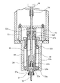
- FIG. 2 shows a schematic diagram of an embodiment of an ultrasonic processing apparatus according to the present invention. That is, with reference to FIG. 2, the ultrasonic processing apparatus of the present invention will be specifically described as follows.
- the ultrasonic processing apparatus of FIG. 2 is a bolt-clamped Langevin type ultrasonic transducer 23 having a structure in which a front mass 22a and a rear mass 22b are fixed to each of front and rear surfaces of piezoelectric elements 21a and 21b having electrodes, respectively, by bolting.
- the tool support 24 provided at the tip of the bolted Langevin type ultrasonic transducer 23, the bolted Langevin type ultrasonic transducer 23 and the central axis from the rear end surface of the rear mass 22b of the bolted Langevin type ultrasonic transducer 23
- a shaft 25 extending in a state where they are matched, a rotation driving means 26 which is coupled to the shaft 25 to give a rotational driving force, a front flange 27a provided around the front mass 22a of the bolted Langevin type ultrasonic transducer 23, a shaft Rear flange 27b provided around 25, bolt tightening Langeva Is disposed around the ultrasonic transducer 23 and engaged in a state sandwiched between the front flange 27a and the rear flange 27b, thereby applying a tension extending vertically to the bolted Langevin ultrasonic transducer 23.
- a rotating casing 28 that supports the bolted Langevin type ultrasonic transducer 23, and a fixed
- a drill 30 is used as a processing tool, and this drill 30 is attached to the tool support means 24.
- the rotation drive means for example, a motor
- the shaft 25 is coupled to each other through a joint 34.
- the engagement between the shaft 25 and the rear flange 27b is realized by the engagement between the rear flange 27b having a tightening nut structure and a screw structure formed on the shaft 25.
- the coupling between the shaft 25 and the rotational drive means (motor) 26 is not necessarily performed through a joint, and may be coupled directly. Further, the rotation driving force may be transmitted by a combination of a known motor and a rotation transmission means (eg, gear, belt).
- a rotation transmission means eg, gear, belt
- Supply of electric power (electric energy) to each electrode of the piezoelectric elements 21a and 21b of the bolted Langevin type ultrasonic transducer 23 is performed by a fixed rotary transformer 32a and a shaft provided in a fixed structure 31 that fixes and supports the fixed casing 29.
- Rotating through a power supply means composed of a rotary rotary transformer 32b fixed to 25 (the power supply means composed of the fixed rotary transformer and the rotary rotary transformer is well known)
- Wiring (connecting through a hole provided in the rear flange 27b, not shown) for electrically connecting the side rotary transformer 32b and each electrode of the piezoelectric elements 21a and 21b is provided.
- the rotatable support of the rotary casing 28 by the fixed casing 29 is also performed using the ball bearings 33a and 33b, and such a rotatable support structure of the rotary casing is also known.
- the length and thickness of the shaft are not particularly limited, but the ratio of the shaft diameter to the diameter of the piezoelectric element of the bolted Langevin type ultrasonic vibrator is preferably in the range of 0.1 to 0.75. .
- the ratio of the shaft length to the length of the bolted Langevin type ultrasonic transducer is preferably in the range of 0.5 to 5 (particularly in the range of 1 to 5).
- the shaft 5 may be formed integrally with the rear mass 22b of the bolted Langevin type ultrasonic transducer 23, but the shaft 5 moves integrally with the rear mast 22b by an adhesive or other joining means on the rear mass 22b. You may join so that it may rotate.
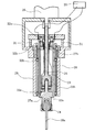
- each configuration in another embodiment of the ultrasonic machining apparatus according to the present invention shown in FIG. 3 is basically the same as the configuration shown in FIG. That is, the ultrasonic processing apparatus of FIG. 3 also has bolted Langevin type ultrasonic transducers 23 each having a structure in which a front mass 22a and a rear mass 22b are fixed by bolting to the front and rear surfaces of a piezoelectric element having electrodes, respectively.
- the tool support means 24 provided at the tip of the bolted Langevin type ultrasonic transducer 23 and the rear end face of the rear mass 22b of the bolted Langevin type ultrasonic transducer 23 are connected to the bolted Langevin type ultrasonic transducer 23 and the central axis.
- a milling tool 30a is used as a processing tool, and this milling tool 30a is attached to the tool support means 24.
- FIG. 3 shows power supply means (ultrasonic transmission circuit) 35 to the fixed-side rotary transformer, and each of the piezoelectric elements of the rotary-side rotary transformer 32b and the bolted Langevin type ultrasonic transducer 23. Wiring (connecting through a hole provided in the rear flange 27b) for electrically connecting the electrodes is shown.
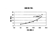
- FIG. 2 is a graph showing the ratio of the longitudinal vibration and the lateral vibration at the tip of the tool 30 measured when the tool (drill) is rotated under application of ultrasonic vibration using the ultrasonic machining apparatus according to the present invention shown in FIG. 4 shows a graph.
- the frequency applied to each electrode of the piezoelectric element of the bolted Langevin type ultrasonic transducer 23 was about 35.2 KHz to about 37.5 KHz.
- the vibration state at the tip of the tool was measured using a Doppler vibrometer.
- the graph of FIG. 4 shows the ratio of the measured longitudinal vibration and lateral vibration of the tool 30 measured by holding the tool using the tool holding means (collet) at the lower end of the ultrasonic machining apparatus.
- a cylindrical rod made of super steel metal having a diameter of 3 mm and a length of 30.0 mm is used.
- the amount of advance of this cylindrical tool means the length of the cylindrical tool which has come out first from a collet.
- the ratio of longitudinal vibration / lateral vibration of the tool tip when the amount of advance (length of advance) of the cylindrical tool is about 5 mm is about 2.7, and the amount of advance (first advance) When the length) was about 21.7 mm, the ratio of longitudinal vibration / lateral vibration at the tool tip was about 20.5.
- the standard advance amount (first advance length) of a drill or milling tool in an ultrasonic processing apparatus is 10 to 25 mm. Therefore, when ultrasonic processing is performed using the ultrasonic processing apparatus shown in FIG. It can be seen that the ratio of the vibration amount (amplitude) of the longitudinal vibration / transverse vibration of the front end portion is about 5 times or more.
- the ratio of the vibration amount (amplitude) of the transverse vibration to the longitudinal vibration becomes very small, and thereby the processing efficiency of the ultrasonic processing is reduced. It can be seen that this is effective in improving the machining accuracy, machining accuracy, and preventing damage to the tool.
Landscapes
- Engineering & Computer Science (AREA)
- Mechanical Engineering (AREA)
- Apparatuses For Generation Of Mechanical Vibrations (AREA)
- Grinding And Polishing Of Tertiary Curved Surfaces And Surfaces With Complex Shapes (AREA)
Abstract
Le dispositif d'usinage ultrasonique de l'invention contient : un transducteur ultrasonique type Langevin à serrage de boulon (23) qui possède sur une face avant et une face arrière d'élément piézoélectrique (21a, 21b), une structure dans laquelle une masse avant (22a) et une masse arrière (22b) sont fixées par serrage de boulon ; un moyen de support d'outil (24) dont est équipée une partie extrémité avant du transducteur ultrasonique (23) ; un arbre (25) qui se prolonge depuis une face extrémité arrière de la masse arrière (22b) ; un moyen d'entraînement en rotation (26) couplé à l'arbre ; un rebord avant (27a) dont est équipée la périphérie de la masse avant (22a) ; un rebord arrière (27b) dont est équipée la périphérie de l'arbre ; une enveloppe rotative (28) disposée à la périphérie du transducteur ultrasonique (23) auquel elle confère une force de traction se prolongeant verticalement et lui permettant de le supporter ; et une enveloppe fixe (29) disposée à la périphérie de l'enveloppe rotative (28) qu'elle supporte de manière à permettre sa rotation.
Applications Claiming Priority (6)
| Application Number | Priority Date | Filing Date | Title |
|---|---|---|---|
| JP2014-151224 | 2014-07-07 | ||
| JP2014151224 | 2014-07-07 | ||
| JP2014-173188 | 2014-08-11 | ||
| JP2014173188 | 2014-08-11 | ||
| JP2015063349 | 2015-03-09 | ||
| JP2015-063349 | 2015-03-09 |
Publications (1)
| Publication Number | Publication Date |
|---|---|
| WO2016006596A1 true WO2016006596A1 (fr) | 2016-01-14 |
Family
ID=55064226
Family Applications (1)
| Application Number | Title | Priority Date | Filing Date |
|---|---|---|---|
| PCT/JP2015/069493 Ceased WO2016006596A1 (fr) | 2014-07-07 | 2015-07-07 | Dispositif d'usinage ultrasonique |
Country Status (1)
| Country | Link |
|---|---|
| WO (1) | WO2016006596A1 (fr) |
Citations (4)
| Publication number | Priority date | Publication date | Assignee | Title |
|---|---|---|---|---|
| JPH0278250U (fr) * | 1988-12-02 | 1990-06-15 | ||
| JP2002346817A (ja) * | 2001-05-21 | 2002-12-04 | Masao Murakawa | 超音波ミリング装置 |
| JP2009241225A (ja) * | 2008-03-31 | 2009-10-22 | Masahiko Jin | 超音波スピンドル装置 |
| WO2014017460A1 (fr) * | 2012-07-23 | 2014-01-30 | Ohnishi Kazumasa | Structure de support pour vibreur ultrasonique équipé d'un outil |
-
2015
- 2015-07-07 WO PCT/JP2015/069493 patent/WO2016006596A1/fr not_active Ceased
Patent Citations (4)
| Publication number | Priority date | Publication date | Assignee | Title |
|---|---|---|---|---|
| JPH0278250U (fr) * | 1988-12-02 | 1990-06-15 | ||
| JP2002346817A (ja) * | 2001-05-21 | 2002-12-04 | Masao Murakawa | 超音波ミリング装置 |
| JP2009241225A (ja) * | 2008-03-31 | 2009-10-22 | Masahiko Jin | 超音波スピンドル装置 |
| WO2014017460A1 (fr) * | 2012-07-23 | 2014-01-30 | Ohnishi Kazumasa | Structure de support pour vibreur ultrasonique équipé d'un outil |
Similar Documents
| Publication | Publication Date | Title |
|---|---|---|
| JP4856650B2 (ja) | 切削もしくは研削装置 | |
| CN109843487B (zh) | 超声波振动赋予用具及超声波加工装置 | |
| JP6758715B2 (ja) | ランジュバン型超音波振動子の振動励起方法及び超音波加工方法と超音波送信方法 | |
| WO2014017460A1 (fr) | Structure de support pour vibreur ultrasonique équipé d'un outil | |
| US7347766B2 (en) | Cutting method and cutting apparatus | |
| CN103710494A (zh) | 一种基于超声波的小孔强化方法及装置 | |
| JP2009291911A (ja) | ラップ装置 | |
| JP2018192467A (ja) | ランジュバン型超音波振動子とその支持方法とその超音波応用加工法 | |
| CN208895761U (zh) | 玻璃板的端面加工装置 | |
| JPH08155799A (ja) | 超音波微細孔加工装置 | |
| JPH10249684A (ja) | 超音波加工装置 | |
| JP6682252B2 (ja) | 研磨具と研磨装置 | |
| JP5957338B2 (ja) | 研削装置 | |
| JP6884363B2 (ja) | 超音波加工用のランジュバン型超音波振動発生装置 | |
| CN104439892B (zh) | 一种单激励超声椭圆振动挤压加工装置 | |
| CN112188938B (zh) | 超声波振动赋予用具、行进波产生装置及超声波加工装置 | |
| CN204321752U (zh) | 一种单激励超声椭圆振动无心磨削装置 | |
| CN107790996A (zh) | 一种轴承压紧安装装置 | |
| CN113444870A (zh) | 一种超声冲击振动时效系统 | |
| JP2018176136A (ja) | ランジュバン型超音波振動子の支持方法とその駆動方法 | |
| CN208663361U (zh) | 玻璃板的端面加工装置 | |
| JP2010205898A (ja) | 超音波振動切削装置 | |
| JP2007130746A (ja) | 切削工具および機械加工装置 | |
| JP2018176136A5 (ja) | ランジュバン型超音波振動子の支持構造体 | |
| CN104440417B (zh) | 一种单激励超声椭圆振动无心磨削装置 |
Legal Events
| Date | Code | Title | Description |
|---|---|---|---|
| 121 | Ep: the epo has been informed by wipo that ep was designated in this application |
Ref document number: 15818857 Country of ref document: EP Kind code of ref document: A1 |
|
| NENP | Non-entry into the national phase |
Ref country code: DE |
|
| NENP | Non-entry into the national phase |
Ref country code: JP |
|
| 122 | Ep: pct application non-entry in european phase |
Ref document number: 15818857 Country of ref document: EP Kind code of ref document: A1 |