WO2016009460A1 - Détecteur photoélectrique de fumée - Google Patents
Détecteur photoélectrique de fumée Download PDFInfo
- Publication number
- WO2016009460A1 WO2016009460A1 PCT/JP2014/003717 JP2014003717W WO2016009460A1 WO 2016009460 A1 WO2016009460 A1 WO 2016009460A1 JP 2014003717 W JP2014003717 W JP 2014003717W WO 2016009460 A1 WO2016009460 A1 WO 2016009460A1
- Authority
- WO
- WIPO (PCT)
- Prior art keywords
- transparent member
- light
- explosion
- light emitting
- photoelectric smoke
- Prior art date
- Legal status (The legal status is an assumption and is not a legal conclusion. Google has not performed a legal analysis and makes no representation as to the accuracy of the status listed.)
- Ceased
Links
Images


Classifications
-
- G—PHYSICS
- G01—MEASURING; TESTING
- G01N—INVESTIGATING OR ANALYSING MATERIALS BY DETERMINING THEIR CHEMICAL OR PHYSICAL PROPERTIES
- G01N21/00—Investigating or analysing materials by the use of optical means, i.e. using sub-millimetre waves, infrared, visible or ultraviolet light
- G01N21/17—Systems in which incident light is modified in accordance with the properties of the material investigated
- G01N21/47—Scattering, i.e. diffuse reflection
- G01N21/49—Scattering, i.e. diffuse reflection within a body or fluid
- G01N21/53—Scattering, i.e. diffuse reflection within a body or fluid within a flowing fluid, e.g. smoke
- G01N21/532—Scattering, i.e. diffuse reflection within a body or fluid within a flowing fluid, e.g. smoke with measurement of scattering and transmission
-
- G—PHYSICS
- G01—MEASURING; TESTING
- G01D—MEASURING NOT SPECIALLY ADAPTED FOR A SPECIFIC VARIABLE; ARRANGEMENTS FOR MEASURING TWO OR MORE VARIABLES NOT COVERED IN A SINGLE OTHER SUBCLASS; TARIFF METERING APPARATUS; MEASURING OR TESTING NOT OTHERWISE PROVIDED FOR
- G01D11/00—Component parts of measuring arrangements not specially adapted for a specific variable
- G01D11/24—Housings ; Casings for instruments
- G01D11/245—Housings for sensors
-
- G—PHYSICS
- G01—MEASURING; TESTING
- G01J—MEASUREMENT OF INTENSITY, VELOCITY, SPECTRAL CONTENT, POLARISATION, PHASE OR PULSE CHARACTERISTICS OF INFRARED, VISIBLE OR ULTRAVIOLET LIGHT; COLORIMETRY; RADIATION PYROMETRY
- G01J1/00—Photometry, e.g. photographic exposure meter
- G01J1/42—Photometry, e.g. photographic exposure meter using electric radiation detectors
- G01J1/44—Electric circuits
-
- G—PHYSICS
- G01—MEASURING; TESTING
- G01N—INVESTIGATING OR ANALYSING MATERIALS BY DETERMINING THEIR CHEMICAL OR PHYSICAL PROPERTIES
- G01N33/00—Investigating or analysing materials by specific methods not covered by groups G01N1/00 - G01N31/00
- G01N33/0004—Gaseous mixtures, e.g. polluted air
- G01N33/0009—General constructional details of gas analysers, e.g. portable test equipment
- G01N33/0062—General constructional details of gas analysers, e.g. portable test equipment concerning the measuring method or the display, e.g. intermittent measurement or digital display
- G01N33/0063—General constructional details of gas analysers, e.g. portable test equipment concerning the measuring method or the display, e.g. intermittent measurement or digital display using a threshold to release an alarm or displaying means
-
- G—PHYSICS
- G08—SIGNALLING
- G08B—SIGNALLING SYSTEMS, e.g. PERSONAL CALLING SYSTEMS; ORDER TELEGRAPHS; ALARM SYSTEMS
- G08B17/00—Fire alarms; Alarms responsive to explosion
- G08B17/10—Actuation by presence of smoke or gases, e.g. automatic alarm devices for analysing flowing fluid materials by the use of optical means
- G08B17/103—Actuation by presence of smoke or gases, e.g. automatic alarm devices for analysing flowing fluid materials by the use of optical means using a light emitting and receiving device
- G08B17/107—Actuation by presence of smoke or gases, e.g. automatic alarm devices for analysing flowing fluid materials by the use of optical means using a light emitting and receiving device for detecting light-scattering due to smoke
-
- G—PHYSICS
- G08—SIGNALLING
- G08B—SIGNALLING SYSTEMS, e.g. PERSONAL CALLING SYSTEMS; ORDER TELEGRAPHS; ALARM SYSTEMS
- G08B17/00—Fire alarms; Alarms responsive to explosion
- G08B17/10—Actuation by presence of smoke or gases, e.g. automatic alarm devices for analysing flowing fluid materials by the use of optical means
- G08B17/11—Actuation by presence of smoke or gases, e.g. automatic alarm devices for analysing flowing fluid materials by the use of optical means using an ionisation chamber for detecting smoke or gas
- G08B17/113—Constructional details
-
- G—PHYSICS
- G01—MEASURING; TESTING
- G01N—INVESTIGATING OR ANALYSING MATERIALS BY DETERMINING THEIR CHEMICAL OR PHYSICAL PROPERTIES
- G01N2201/00—Features of devices classified in G01N21/00
- G01N2201/02—Mechanical
- G01N2201/023—Controlling conditions in casing
- G01N2201/0236—Explosion proof
Definitions
- the photoelectric smoke detector includes a light emitting unit and a light receiving unit, and recognizes the generation of smoke when the light receiving unit detects light scattered by air containing smoke.
- the photoelectric smoke detector generally includes an electronic circuit board for controlling the functions of the light emitting unit and the light receiving unit.
- an overcurrent is temporarily caused by an electronic component defect, and thus a spark may be generated, or an abnormally high temperature state may be caused by deterioration of an insulation resistance on the surface of the board. Sparks and abnormally high temperature parts in electronic circuit boards can ignite combustible gases and cause explosions.
- Patent Document 1 Japanese Patent No. 3938750 discloses a photoelectric smoke detector that employs an explosion-proof method called an intrinsically safe explosion-proof type.
- the intrinsically safe explosion-proof photoelectric smoke detector suppresses the magnitude of the current flowing through the electronic circuit board, thereby preventing an electric spark that can ignite the combustible gas from being generated on the surface of the electronic circuit board.
- Patent Document 3 states that “a light emitter, a direct light, and a scattered light receiver are housed in a metal case of a circuit part, and these are connected to a smoke detector dark box by an optical fiber, and a lens is attached to the end of the dark box side optical fiber. It is configured to detect smoke particles with the action of light emission and light reception ”(Patent Document 3, page (2), from the lower right column to the first line to the lower left column) (5th line). Furthermore, Patent Document 4 states that “a labyrinth base for introducing smoke and an electronic circuit such as a light-emitting element, a light-receiving element, and an electronic component are separated and connected by an optical fiber, so that they are not affected by high temperatures.
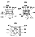
- FIG. 8 is a cross-sectional view taken along (d)-(d) in FIG. 9A is a longitudinal sectional view of the light emitting device 35A
- FIG. 9B is a sectional view taken along lines (e)-(e) in FIG. 6
- FIG. 9C is a sectional view around the transparent member A62.
- 10A is a longitudinal sectional view of the light receiving device 35B
- FIG. 10B is a sectional view of (f)-(f) in FIG. 7
- FIG. 10C is a sectional view of the periphery of the transparent member B72. It is.
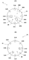
- a large number of shielding plates 24 are provided so as to surround the inside of the detection unit 23, and have a function of preventing light leakage from the outside to the inside of the detection unit 23 and light intrusion from the inside to the outside. Further, air containing smoke can enter from the outside to the inside of the detection unit 23 through a gap provided between the shielding plates 24.
- the light emitting device holder 25 ⁇ / b> A and the light emitting device holder 25 ⁇ / b> B have a cavity having a size capable of holding the light emitting device and the light receiving device therein.
- the indicator lamp holder 26 includes a cylindrical hollow space penetrating from the front surface to the back surface of the labyrinth 2, and an indicator lamp to be described later penetrates the hollow space.
- the positions of the fixing screw holes 31A to 31D in the optical device installation base 31 correspond to the positions of the notches 21A to D in the labyrinth 2, and the cover on the optical device installation base 31
- the positions of the mounting screw holes 32A to 32D correspond to the positions of the cover mounting screw holes 22A to 22D in the labyrinth 2.
- a light emitting device 35A, a light receiving device 35B, and an indicator lamp 36 protrude from the surface side of the optical device installation base 3.
- the first positioning portions 38A and 38B are provided on the surface side of the optical device mounting base 31.
- the first positioning portion 38A and the second positioning portion 38B are respectively provided on the back surface side of the labyrinth 2 shown in FIG. 2B, in other words, on the laminated surface side with the optical device installation base 31 in the labyrinth 2.
- the labyrinth is formed by fitting the pins into the holes. Misalignment between 2 and the optical member 3 is prevented.
- the first positioning portion 38A is provided at the center of the circle that forms the planar edge of the optical device installation base 31, and the second positioning portion 38B is provided on the radius of the circle that forms the planar edge of the optical device installation base 31. .
- the second positioning portion 38B exists at a position that bisects the length of a straight line connecting the center of the circle forming the planar edge of the optical device installation base 31 and the point on the edge.
- the first fixing portion 28 ⁇ / b> A is provided at the center of the circle that forms the planar edge of the labyrinth 2
- the second fixing portion 28 ⁇ / b> B is provided on the radial circumference of the circle that forms the planar edge of the labyrinth 2.
- an electronic circuit board 51, a protective plate 52 for protecting the electronic circuit board 51, and the like are provided on the back side of the optical device installation base 31.
- the area of the planar shape of the electronic circuit board 51 and the area of the planar shape of the protective plate 52 are smaller than the area of the planar shape of the optical device installation base 31 in the example in FIG. Therefore, the electronic circuit board 51 and the protective plate 52 are not observed in the plan view shown in FIG.
- a back surface opening 36A and a back surface opening 36B are provided on the back surface side of the optical device installation base 31.
- the housing 4 in the present invention Since the housing 4 in the present invention has sufficient strength, it is not damaged even by an explosion in the circuit housing portion 44. Specifically, the casing 4 in the present invention is not damaged even if a pressure of a magnitude determined by the explosion-proof regulations, for example, a pressure of about 1.5 MPa is applied by an explosion in the circuit housing portion 44. , Formed of iron plate or the like. Therefore, the flame generated by the explosion in the circuit housing portion 44 does not leak out of the photoelectric smoke detector 1 when the housing 4 is damaged.
Landscapes
- Physics & Mathematics (AREA)
- General Physics & Mathematics (AREA)
- Chemical & Material Sciences (AREA)
- Analytical Chemistry (AREA)
- Business, Economics & Management (AREA)
- Emergency Management (AREA)
- Health & Medical Sciences (AREA)
- Life Sciences & Earth Sciences (AREA)
- Biochemistry (AREA)
- General Health & Medical Sciences (AREA)
- Immunology (AREA)
- Pathology (AREA)
- Engineering & Computer Science (AREA)
- Combustion & Propulsion (AREA)
- Food Science & Technology (AREA)
- Medicinal Chemistry (AREA)
- Spectroscopy & Molecular Physics (AREA)
- Fire-Detection Mechanisms (AREA)
- Investigating Or Analysing Materials By Optical Means (AREA)
Abstract
Priority Applications (7)
| Application Number | Priority Date | Filing Date | Title |
|---|---|---|---|
| RU2016126414A RU2646195C1 (ru) | 2014-07-14 | 2014-07-14 | Фотоэлектрический детектор дыма |
| KR1020167017712A KR101874970B1 (ko) | 2014-07-14 | 2014-07-14 | 광전식 연기 감지기 |
| JP2014560966A JP5771760B1 (ja) | 2014-07-14 | 2014-07-14 | 光電式煙感知器 |
| EP14897830.7A EP3171347B1 (fr) | 2014-07-14 | 2014-07-14 | Détecteur photoélectrique de fumée |
| PCT/JP2014/003717 WO2016009460A1 (fr) | 2014-07-14 | 2014-07-14 | Détecteur photoélectrique de fumée |
| CN201480071539.4A CN106663356B (zh) | 2014-07-14 | 2014-07-14 | 光电式烟雾传感器 |
| US15/190,498 US10054542B2 (en) | 2014-07-14 | 2016-06-23 | Photoelectric smoke detector |
Applications Claiming Priority (1)
| Application Number | Priority Date | Filing Date | Title |
|---|---|---|---|
| PCT/JP2014/003717 WO2016009460A1 (fr) | 2014-07-14 | 2014-07-14 | Détecteur photoélectrique de fumée |
Related Child Applications (1)
| Application Number | Title | Priority Date | Filing Date |
|---|---|---|---|
| US15/190,498 Continuation-In-Part US10054542B2 (en) | 2014-07-14 | 2016-06-23 | Photoelectric smoke detector |
Publications (1)
| Publication Number | Publication Date |
|---|---|
| WO2016009460A1 true WO2016009460A1 (fr) | 2016-01-21 |
Family
ID=54188029
Family Applications (1)
| Application Number | Title | Priority Date | Filing Date |
|---|---|---|---|
| PCT/JP2014/003717 Ceased WO2016009460A1 (fr) | 2014-07-14 | 2014-07-14 | Détecteur photoélectrique de fumée |
Country Status (7)
| Country | Link |
|---|---|
| US (1) | US10054542B2 (fr) |
| EP (1) | EP3171347B1 (fr) |
| JP (1) | JP5771760B1 (fr) |
| KR (1) | KR101874970B1 (fr) |
| CN (1) | CN106663356B (fr) |
| RU (1) | RU2646195C1 (fr) |
| WO (1) | WO2016009460A1 (fr) |
Cited By (4)
| Publication number | Priority date | Publication date | Assignee | Title |
|---|---|---|---|---|
| KR20170090366A (ko) * | 2016-01-28 | 2017-08-07 | 닛폰 도라이 케미카루 가부시키가이샤 | 광전식 연기 감지기 |
| US10151693B2 (en) | 2015-08-25 | 2018-12-11 | Fenwal Controls Of Japan, Ltd. | Photoelectric smoke sensor |
| WO2020003712A1 (fr) | 2018-06-25 | 2020-01-02 | ホーチキ株式会社 | Dispositif de détection d'incendie |
| TWI788369B (zh) * | 2017-06-14 | 2023-01-01 | 日商報知希股份有限公司 | 警報裝置 |
Families Citing this family (11)
| Publication number | Priority date | Publication date | Assignee | Title |
|---|---|---|---|---|
| CN107478576B (zh) * | 2016-06-07 | 2024-02-20 | 宁波方太厨具有限公司 | 一种油烟传感器的防护结构 |
| KR101876898B1 (ko) * | 2018-01-25 | 2018-07-10 | 주식회사 아이알티코리아 | 불꽃 감지기 |
| EP3791371B1 (fr) | 2018-05-09 | 2024-04-10 | Carrier Corporation | Chambre à fumée pour détecteur de fumée à angles multiples et ondes multiples |
| CN111199628A (zh) | 2018-11-20 | 2020-05-26 | 海湾安全技术有限公司 | 烟雾探测器 |
| JP6661153B1 (ja) * | 2019-04-25 | 2020-03-11 | 株式会社千代田防災 | 防火及び防排煙設備用煙感知器の取付け装置 |
| CN110009865A (zh) * | 2019-05-13 | 2019-07-12 | 中国船舶重工集团公司第七0三研究所 | n型防爆吸气式感烟探测器 |
| CN110567850A (zh) * | 2019-08-26 | 2019-12-13 | 苏州双刘精密仪器有限公司 | 基于大数据分析的高灵敏光纤传感系统 |
| ES2975584T3 (es) * | 2020-05-08 | 2024-07-09 | Carrier Corp | Prevención de condensación en un sistema de detección de humo por aspiración |
| US11959857B2 (en) | 2020-09-25 | 2024-04-16 | Electronics And Telecommunications Research Institute | Apparatus for measuring Raman scattering, and apparatus and method for determining true fire using the apparatus |
| EP4239608B1 (fr) * | 2020-10-30 | 2026-03-25 | Hochiki Corporation | Appareil de prévention de catastrophes |
| CN117175045B (zh) * | 2023-11-02 | 2024-03-22 | 安徽中科中涣智能装备股份有限公司 | 一种基于光谱的电池箱热失控探测装置 |
Citations (2)
| Publication number | Priority date | Publication date | Assignee | Title |
|---|---|---|---|---|
| JPH11175860A (ja) * | 1997-12-16 | 1999-07-02 | Nohmi Bosai Ltd | 防爆用熱感知器 |
| JP2002358583A (ja) * | 2001-05-31 | 2002-12-13 | Nittan Co Ltd | 火災検知器 |
Family Cites Families (39)
| Publication number | Priority date | Publication date | Assignee | Title |
|---|---|---|---|---|
| US3555532A (en) * | 1968-10-29 | 1971-01-12 | Graham Stuart Corp | Vapor or particle detection device |
| CH508251A (de) * | 1970-07-23 | 1971-05-31 | Cerberus Ag | Ionisationsfeuermelder |
| US4396840A (en) * | 1980-10-01 | 1983-08-02 | Matsushita Electric Works, Ltd. | Ionization type smoke sensing device |
| JPS58129145A (ja) | 1982-01-28 | 1983-08-02 | Mitsubishi Electric Corp | 貯湯式電気温水器の制御装置 |
| JPS58129145U (ja) | 1982-02-25 | 1983-09-01 | ホーチキ株式会社 | 光電式分離型煙感知装置 |
| US4539556A (en) * | 1983-04-15 | 1985-09-03 | Pittway Corporation | Combustion products detector with accelerated test |
| CA1267735A (fr) * | 1986-01-17 | 1990-04-10 | Nohmi Bosai Kogyo Co., Ltd. | Detecteur de fumee, du type a ionisation |
| JPS638538A (ja) | 1986-06-27 | 1988-01-14 | Matsushita Electric Ind Co Ltd | 煙感知器 |
| JPS6320050A (ja) | 1986-07-10 | 1988-01-27 | Kotobuki Giken Kogyo Kk | スクリユ−デカンタ型遠心濃縮機 |
| JPS63163698A (ja) * | 1986-12-26 | 1988-07-07 | ホーチキ株式会社 | 散乱光式煙感知器 |
| JPS63239592A (ja) * | 1987-03-27 | 1988-10-05 | ホーチキ株式会社 | 光電式煙感知器 |
| US5021677A (en) * | 1989-05-02 | 1991-06-04 | Nohmi Bosai Kabushiki Kaisha | Light-scattering-type smoke detector |
| FR2666163B1 (fr) * | 1990-08-22 | 1995-03-17 | Bertin & Cie | Dispositif opto-electronique de detection de fumees ou de gaz en suspension dans l'air. |
| CN1053677A (zh) * | 1991-02-09 | 1991-08-07 | 北京市天坛仪器仪表公司 | 测量可燃气体浓度用复合传感器 |
| CN2107741U (zh) * | 1991-11-19 | 1992-06-17 | 山西耀华高技术公司 | 红外矿用防爆摄录装置 |
| DE69317147T2 (de) * | 1992-04-25 | 1998-10-01 | Nohmi Bosai Ltd | Feuermelder |
| US5400014A (en) * | 1993-07-12 | 1995-03-21 | Detection Systems, Inc. | Smoke detector with dark chamber |
| JP2787001B2 (ja) * | 1994-12-12 | 1998-08-13 | ホーチキ株式会社 | 光電式煙感知器 |
| EP0821330B1 (fr) * | 1996-07-22 | 2002-09-04 | Siemens Building Technologies AG | Détecteur de fumée |
| CA2293830C (fr) * | 1999-12-31 | 2008-07-29 | Digital Security Controls Ltd. | Detecteur de fumee photo-electrique et chambre connexe |
| US6778091B2 (en) * | 2001-01-09 | 2004-08-17 | Qualey, Iii James R. | Smoke chamber |
| CN2466613Y (zh) * | 2001-02-08 | 2001-12-19 | 高明 | 防爆耐压式光电液位传感器 |
| AU762183B2 (en) * | 2001-04-24 | 2003-06-19 | Matsushita Electric Works Ltd. | Fire detector unit |
| JP3938750B2 (ja) | 2003-01-27 | 2007-06-27 | ホーチキ株式会社 | 煙感知器 |
| RU2288505C1 (ru) * | 2005-03-21 | 2006-11-27 | Закрытое акционерное общество "Светлана-Оптоэлектроника" | Детектор дыма |
| RU49321U1 (ru) * | 2005-03-28 | 2005-11-10 | Общество с ограниченной ответственностью "Конструкторское Бюро Пожарной Автоматики" | Корпус извещателя пожарного с защитным экраном |
| JP4866348B2 (ja) * | 2005-03-31 | 2012-02-01 | 日本フェンオール株式会社 | 光電式煙感知器 |
| EA007638B1 (ru) * | 2005-04-12 | 2006-12-29 | Одо "Бмк-Систем" | Извещатель пожарный дымовой |
| EP2264676B1 (fr) * | 2008-03-24 | 2019-09-04 | Panasonic Intellectual Property Management Co., Ltd. | Capteur |
| JP5153709B2 (ja) * | 2009-03-31 | 2013-02-27 | 能美防災株式会社 | 光電式煙感知器 |
| KR20100037539A (ko) * | 2008-10-01 | 2010-04-09 | 노미 보사이 가부시키가이샤 | 광전식 연기 감지기 |
| CN201374114Y (zh) * | 2009-04-03 | 2009-12-30 | 郑州净瓶高科有限公司 | 防爆型火灾探测装置 |
| CN101750149A (zh) * | 2010-01-14 | 2010-06-23 | 内蒙古科技大学 | 真空腔式辐射源温度传感器 |
| CN102338737A (zh) * | 2010-07-21 | 2012-02-01 | 友丽系统制造股份有限公司 | 光电式气体感测装置及其制造方法 |
| WO2013001966A1 (fr) * | 2011-06-30 | 2013-01-03 | ホーチキ株式会社 | Appareil de détection de fumée à lumière diffusée |
| KR101269239B1 (ko) * | 2012-05-04 | 2013-05-30 | (주)우창전기산업 | 배리어를 갖는 방폭형 연기 감지기 |
| DE102013213721B4 (de) * | 2013-03-07 | 2015-10-22 | Siemens Schweiz Ag | Brandmeldeanlage für den Einsatz in einem Nuklearbereich oder EX-Bereich |
| US9514623B1 (en) * | 2015-05-15 | 2016-12-06 | Google Inc. | Smoke detector chamber architecture and related methods using two different wavelengths of light |
| US9196141B1 (en) * | 2015-05-15 | 2015-11-24 | Google, Inc. | Smoke detector chamber |
-
2014
- 2014-07-14 RU RU2016126414A patent/RU2646195C1/ru active
- 2014-07-14 EP EP14897830.7A patent/EP3171347B1/fr active Active
- 2014-07-14 KR KR1020167017712A patent/KR101874970B1/ko active Active
- 2014-07-14 CN CN201480071539.4A patent/CN106663356B/zh active Active
- 2014-07-14 JP JP2014560966A patent/JP5771760B1/ja active Active
- 2014-07-14 WO PCT/JP2014/003717 patent/WO2016009460A1/fr not_active Ceased
-
2016
- 2016-06-23 US US15/190,498 patent/US10054542B2/en active Active
Patent Citations (2)
| Publication number | Priority date | Publication date | Assignee | Title |
|---|---|---|---|---|
| JPH11175860A (ja) * | 1997-12-16 | 1999-07-02 | Nohmi Bosai Ltd | 防爆用熱感知器 |
| JP2002358583A (ja) * | 2001-05-31 | 2002-12-13 | Nittan Co Ltd | 火災検知器 |
Cited By (8)
| Publication number | Priority date | Publication date | Assignee | Title |
|---|---|---|---|---|
| US10151693B2 (en) | 2015-08-25 | 2018-12-11 | Fenwal Controls Of Japan, Ltd. | Photoelectric smoke sensor |
| KR20170090366A (ko) * | 2016-01-28 | 2017-08-07 | 닛폰 도라이 케미카루 가부시키가이샤 | 광전식 연기 감지기 |
| JP2017138968A (ja) * | 2016-01-28 | 2017-08-10 | 日本ドライケミカル株式会社 | 光電式煙感知器 |
| KR102554162B1 (ko) * | 2016-01-28 | 2023-07-12 | 닛폰 도라이 케미카루 가부시키가이샤 | 광전식 연기 감지기 |
| TWI788369B (zh) * | 2017-06-14 | 2023-01-01 | 日商報知希股份有限公司 | 警報裝置 |
| WO2020003712A1 (fr) | 2018-06-25 | 2020-01-02 | ホーチキ株式会社 | Dispositif de détection d'incendie |
| US11614396B2 (en) | 2018-06-25 | 2023-03-28 | Hochiki Corporation | Fire detection device |
| US12235206B2 (en) | 2018-06-25 | 2025-02-25 | Hochiki Corporation | Fire detection apparatus |
Also Published As
| Publication number | Publication date |
|---|---|
| CN106663356B (zh) | 2019-02-22 |
| EP3171347A4 (fr) | 2017-11-29 |
| US20160305874A1 (en) | 2016-10-20 |
| EP3171347B1 (fr) | 2020-06-10 |
| US10054542B2 (en) | 2018-08-21 |
| JP5771760B1 (ja) | 2015-09-02 |
| EP3171347A1 (fr) | 2017-05-24 |
| JPWO2016009460A1 (ja) | 2017-04-27 |
| RU2646195C1 (ru) | 2018-03-01 |
| KR101874970B1 (ko) | 2018-07-05 |
| KR20160095036A (ko) | 2016-08-10 |
| CN106663356A (zh) | 2017-05-10 |
Similar Documents
| Publication | Publication Date | Title |
|---|---|---|
| JP5771760B1 (ja) | 光電式煙感知器 | |
| US10151693B2 (en) | Photoelectric smoke sensor | |
| CN108291824B (zh) | 用于发送和接收电磁辐射用的器件的防爆的壳体 | |
| US9170341B2 (en) | Flame-proof radiation detector with wireless communication means | |
| US20120198931A1 (en) | Explosion-proof device | |
| JP2019174463A5 (fr) | ||
| CA3027361A1 (fr) | Enceintes antideflagrantes comprenant des parties de transmission de la lumiere | |
| KR102554162B1 (ko) | 광전식 연기 감지기 | |
| CN107016815A (zh) | 光电式烟雾传感器 | |
| CN114729884B (zh) | 油雾检测装置 | |
| JP4652964B2 (ja) | 防爆型ガスセンサー装置 | |
| KR101229047B1 (ko) | 방폭구조를 갖는 가스감지기 | |
| JP6912358B2 (ja) | ガス検知器 | |
| CN218497611U (zh) | 一种复合型防爆探测器 | |
| KR20250003366A (ko) | 방폭 위험지역에서 사용 가능한 범용 가스 감지기 | |
| HK40076472B (zh) | 油雾检测装置 | |
| JP2001041844A (ja) | 漏液センサー |
Legal Events
| Date | Code | Title | Description |
|---|---|---|---|
| ENP | Entry into the national phase |
Ref document number: 2014560966 Country of ref document: JP Kind code of ref document: A |
|
| 121 | Ep: the epo has been informed by wipo that ep was designated in this application |
Ref document number: 14897830 Country of ref document: EP Kind code of ref document: A1 |
|
| ENP | Entry into the national phase |
Ref document number: 20167017712 Country of ref document: KR Kind code of ref document: A |
|
| REEP | Request for entry into the european phase |
Ref document number: 2014897830 Country of ref document: EP |
|
| WWE | Wipo information: entry into national phase |
Ref document number: 2014897830 Country of ref document: EP |
|
| NENP | Non-entry into the national phase |
Ref country code: DE |
|
| ENP | Entry into the national phase |
Ref document number: 2016126414 Country of ref document: RU Kind code of ref document: A |