WO2016009575A1 - Dispositif de câblage - Google Patents
Dispositif de câblage Download PDFInfo
- Publication number
- WO2016009575A1 WO2016009575A1 PCT/JP2015/000791 JP2015000791W WO2016009575A1 WO 2016009575 A1 WO2016009575 A1 WO 2016009575A1 JP 2015000791 W JP2015000791 W JP 2015000791W WO 2016009575 A1 WO2016009575 A1 WO 2016009575A1
- Authority
- WO
- WIPO (PCT)
- Prior art keywords
- cover
- container
- terminal
- piece
- wiring device
- Prior art date
- Legal status (The legal status is an assumption and is not a legal conclusion. Google has not performed a legal analysis and makes no representation as to the accuracy of the status listed.)
- Ceased
Links
Images






Classifications
-
- H—ELECTRICITY
- H01—ELECTRIC ELEMENTS
- H01H—ELECTRIC SWITCHES; RELAYS; SELECTORS; EMERGENCY PROTECTIVE DEVICES
- H01H9/00—Details of switching devices, not covered by groups H01H1/00 - H01H7/00
- H01H9/02—Bases, casings, or covers
-
- H—ELECTRICITY
- H01—ELECTRIC ELEMENTS
- H01H—ELECTRIC SWITCHES; RELAYS; SELECTORS; EMERGENCY PROTECTIVE DEVICES
- H01H23/00—Tumbler or rocker switches, i.e. switches characterised by being operated by rocking an operating member in the form of a rocker button
- H01H23/02—Details
- H01H23/04—Cases; Covers
Definitions
- the present invention generally relates to a wiring device, and more particularly to an embedded wiring device that is attached using a switch box or the like.
- an embedded switch device that is attached to a switch box and has one or a plurality of reversing switch mechanisms
- the switch device described in Document 1 includes three sets of reversing switch mechanisms built into one body. In this switch device, it is possible to make the width dimension (longitudinal dimension) of the body difficult to be affected by the dimensional variation of the switch box.
- a container that can accommodate three sets of reversing switch mechanisms is configured by engaging a cover with the body.
- a cover when stress is applied to at least one of the body and the cover, there is a possibility that distortion occurs in the body.
- the present invention has been made in view of the above points, and an object of the present invention is to provide a wiring device in which the body is hardly distorted even when stress is applied.
- the wiring device of the present invention includes a container that houses one or more switches.
- the vessel includes a body and a cover that are engaged with each other.
- the body and the cover include a first engagement portion and a second engagement portion.
- the first engaging portion engages the body and the cover with each other at both ends in the first direction of the container.
- the second engaging portion engages the body and the cover with each other at both ends in a second direction different from the first direction of the container.
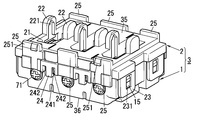
- the wiring device A1 includes a container body 3 that houses one to a plurality of switches S1 (see FIG. 3), as shown in FIGS.
- the container 3 includes a body 1 and a cover 2 that are engaged with each other.
- the body 1 and the cover 2 include a first engagement portion 31 and a second engagement portion 32.
- the first engagement portion 31 engages the body 1 and the cover 2 with each other at both ends in the first direction (longitudinal direction) of the container body 3.
- the second engaging portion 32 engages the body 1 and the cover 2 with each other at both ends in a second direction (short direction) different from the first direction of the container body 3.
- the wiring device A1 of the present embodiment will be described in detail.
- the configuration described below is only an example of the present invention, and the present invention is not limited to the following embodiment, and the technical idea according to the present invention is not deviated from this embodiment.
- Various changes can be made in accordance with the design or the like as long as they are not.
- the arrows shown in FIG. 1 define the vertical and horizontal directions and the front and rear directions.
- the longitudinal direction of the body 1 formed in a box shape is defined as the left-right direction
- the lateral direction is defined as the up-down direction
- the thickness direction is defined as the front-rear direction.
- the definition of the direction is not intended to limit the usage pattern of the wiring device A1 of the present embodiment.
- the wiring device A ⁇ b> 1 of the present embodiment includes a container body 3 including a body 1 and a cover 2, a mounting frame 4, and a decorative plate 5.
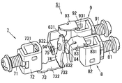
- the wiring device A1 of the present embodiment includes three switches S1 and three operation units 6. Each switch S1 includes a common contact portion 7, a first contact portion 8, and a second contact portion 9.
- the operation unit 6 includes an operation handle 60, a reversing handle 61, and a reversing spring 62.
- the common contact portion 7 includes a terminal screw 71, a terminal frame 72, a common contact plate 73, a movable element 74, and two movable contacts 75.
- the first contact portion 8 includes a terminal screw 81, a terminal frame 82, a first contact plate 83, and a first fixed contact 84.
- the second contact portion 9 includes a terminal screw 91, a terminal frame 92, a second contact plate 93, and a second fixed contact 94.
- the wiring device A1 of the present embodiment is attached to, for example, the switch box B1 shown in FIG.
- the switch box B1 is formed in a box shape with one surface (front surface) opened.
- the switch box B1 is used for embedding in a construction material such as a wall or a ceiling in a state where the wiring device A1 of the present embodiment is accommodated therein.
- the switch box B1 has a dimension that can accommodate the container 3 of the wiring device A1 of the present embodiment.
- Four semicircular assembly pieces B11 are provided on the inner wall of the switch box B1. Each assembly piece B11 is provided on the upper wall, the lower wall, the left wall, and the right wall in the switch box B1.
- Each assembly piece B11 is provided with a circular assembly hole B12 penetrating in the front-rear direction.
- the wiring device A1 of this embodiment is used in a state where the switch box B1 is embedded in the construction material and the decorative plate 5 and the three operation handles 60 are exposed to the outside from the construction material.
- the container 3 (the body 1 and the cover 2) will be described in detail with reference to the drawings.
- the body 1 is formed in a box shape having one surface (front surface) opened by a thermosetting resin material such as urea resin.
- the interior of the body 1 is divided into three first storage chambers 12, three second storage chambers 13, and six third storage chambers 14 by a plurality of partition walls 11. .
- the three first storage chambers 12 are provided at the center in the vertical direction inside the body 1 and arranged along the longitudinal direction (left-right direction) of the body 1.
- Each of the first storage chambers 12 stores the movable element 74, a part of the first contact plate 83, and a part of the second contact plate 93 (see FIG. 10).
- the three second storage chambers 13 are located on the lower side inside the body 1 and are arranged along the longitudinal direction (left-right direction) of the body 1.
- Each second storage chamber 13 stores a terminal screw 71 and a terminal frame 72 of the common contact portion 7 (see FIG. 10).
- a semicircular opening 13 ⁇ / b> A is provided on the lower wall of each second storage chamber 13.
- the head of the terminal screw 71 of the common contact portion 7 is exposed to the outside through the opening 13A.
- a rectangular insertion hole 13B is provided in the bottom (rear wall) of each second storage chamber 13 so as to penetrate in the front-rear direction. An external electric wire can be inserted into the body 1 through these insertion holes 13B.
- the 1st storage chamber 12 and the 2nd storage chamber 13 which adjoin in the up-down direction are connected via the opening 13C.
- the three third storage chambers 14 are located on the upper side inside the body 1 and are arranged along the longitudinal direction (left-right direction) of the body 1.
- the terminal screws 81 and terminal frames 82 of the first contact portions 8 and the terminal screws 91 and terminal frames 92 of the second contact portions 9 are alternately stored so as to be adjacent to each other ( (See FIG. 10).
- a semicircular opening 14 ⁇ / b> A is provided on the upper wall of each third storage chamber 14.
- the head of the terminal screw 81 of the first contact portion 8 and the head of the terminal screw 91 of the second contact portion 9 are exposed to the outside through the opening 14A (see FIG. 2).
- a rectangular insertion hole 14B is provided penetrating in the front-rear direction. An electric wire can be inserted into the body 1 through these insertion holes 14B.
- a pair of first engaging claws 15 are integrally formed at both ends in the longitudinal direction of the body 1 (that is, both the left and right walls).
- Each first engaging claw 15 is provided so as to protrude outward in the left-right direction from the wall surface of the body 1.
- claw 15 has the slope which inclines inward of the left-right direction as it goes to the end (front end).
- a pair of second engaging claws 16 are integrally formed at the first end (that is, the lower wall) in the short direction of the body 1. Further, as shown in FIG. 2, one second engagement claw 16 is integrally formed at the second end (that is, the upper wall) in the short direction of the body 1. Each second engaging claw 16 is provided so as to protrude outward in the vertical direction from the wall surface of the body 1. Each of the second engagement claws 16 has a slope that inclines in the vertical direction toward one end (front end) thereof.
- the cover 2 is formed in a flat box shape with one surface (rear surface) opened by a thermoplastic resin material such as polybutylene terephthalate (PBT) resin.
- a thermoplastic resin material such as polybutylene terephthalate (PBT) resin.
- Three rectangular openings 21 are provided on the front wall of the cover 2. These openings 21 are separated from each other in the longitudinal direction (left-right direction) of the cover 2. Each opening 21 is used for allowing the reversing handle 61 to face the first storage chamber 12 of the body 1.
- three plate-shaped bearings 22 projecting forward are provided on the front wall of the cover 2. A pair of these bearings 22 are provided on the periphery of each opening 21 so as to sandwich the opening 21 in the longitudinal direction (left-right direction) of the cover 2.
- Each pair of bearings 22 is provided with a recess 221 on one surface facing each other.
- Each recess 221 is formed so as to taper toward one end (front end). These bearings 22 are used for holding the reversing handle 61 rotatably on the cover 2.
- a pair of first engaging pieces 23 are integrally formed at both ends in the longitudinal direction of the cover 2 (that is, both the left and right walls).
- Each first engagement piece 23 is formed in a rectangular shape whose longitudinal direction coincides with the front-rear direction.
- Each first engagement piece 23 is provided with a rectangular engagement hole 231 into which the first engagement claw 15 of the body 1 is fitted.
- a pair of second engagement pieces 24 are integrally formed at the first end (lower wall) in the short direction of the cover 2. Further, as shown in FIG. 2, one second engagement piece 24 is integrally formed at the second end (upper wall) in the short direction of the cover 2.
- Each second engagement piece 24 is formed in a rectangular shape so that its longitudinal direction coincides with the front-rear direction.
- a claw 241 that is caught by the second engagement claw 16 of the body 1 is integrally formed.
- slits 242 are provided on both sides of each second engagement piece 24 in the short direction (left-right direction).
- each protruding wall 25 is integrally formed at both ends of the cover 2 in the short direction (that is, both upper and lower walls).
- One end (front end) of each protruding wall 25 protrudes from the front wall of the cover 2.
- the left and right projecting walls 25 are integrally formed with coupling claws 251 as shown in FIG.
- the left and right projecting walls 25 are integrally formed with coupling claws 251 as shown in FIG.
- Each coupling claw 251 is provided so as to protrude outward from the wall surface of each protruding wall 25 in the vertical direction.
- Each coupling claw 251 has a slope that inclines inward in the vertical direction toward one end (front end) thereof.
- the container 3 is completed by attaching the cover 2 to the body 1.
- the container 3 is completed when the body 1 and the cover 2 are engaged with each other.
- the cover 2 is pressed against the body 1 from the front.
- the first engagement claws 15 of the body 1 are fitted into the engagement holes 231 of the first engagement pieces 23 of the cover 2.
- each first engagement claw 15 of the body 1 and each first engagement piece 23 of the cover 2 are engaged with each other.
- the body 1 and the cover 2 are engaged with each other at both ends in the left-right direction (longitudinal direction) of the container body 3.
- each claw 241 of each second engagement piece 24 of the cover 2 is hooked on each second engagement claw 16 of the body 1.
- each second engagement claw 16 of the body 1 and each second engagement piece 24 of the cover 2 are engaged with each other.
- the body 1 and the cover 2 are engaged with each other at both ends in the vertical direction (short direction) of the container 3.
- the cover 2 is attached to the body 1 and the container 3 is completed.
- the first engaging claws 15 of the body 1 and the first engaging pieces 23 of the cover 2 are at both ends in the first direction (longitudinal direction) of the body 3.
- a first engaging portion 31 (see FIG. 1) for engaging the body 1 and the cover 2 with each other is configured.
- each second engagement claw 16 of the body 1 and each second engagement piece 24 of the cover 2 are in a second direction different from the first direction of the body 3 (
- a second engaging portion 32 that engages the body 1 and the cover 2 with each other at both ends in the short direction is configured (see FIG. 1).
- the mounting frame 4 is formed in a rectangular frame shape from a thermoplastic resin material such as ABS resin (see FIG. 3).
- a rectangular opening 41 is provided in the center of the front surface of the mounting frame 4.
- the opening 41 has dimensions that allow the three operation handles 60 to be exposed to the outside.
- attachment holes 42 are provided in the front corners of the attachment frame 4 so as to penetrate in the front-rear direction. Each attachment hole 42 is used for attaching the decorative plate 5 to the attachment frame 4.
- a plurality (six in the figure) of coupling holes 43 are provided in the front-rear direction so as to penetrate the peripheral edge of the upper long side of the opening 41 and the peripheral edge of the lower long side, respectively. Yes.
- These coupling holes 43 are used for attaching the container 3 to the attachment frame 4. That is, the body 3 is attached to the mounting frame 4 by inserting each coupling claw 251 of the cover 2 into the corresponding coupling hole 43 and hooking each coupling claw 251 to the periphery of each coupling hole 43.
- the wiring device A1 of the present embodiment is configured to attach the three-module sized body 3 to the mounting frame 4.
- the one-module sized body or the two-module sized body is attached. It is also possible to attach to the frame 4. That is, by inserting the coupling claws provided in these container bodies into the corresponding coupling holes 43 and hooking the coupling claws on the periphery of the coupling holes, these container bodies are attached to the mounting frame 4.
- two assembly holes 44 are provided through the front surface of the mounting frame 4 in the front-rear direction. These assembly holes 44 are provided on both upper and lower sides across the opening 41. Each assembly hole 44 is used to attach the attachment frame 4 (in other words, the wiring device A1 of the present embodiment) to the switch box B1.
- the decorative plate 5 is formed of a thermoplastic resin material such as polycarbonate (PC) resin, for example, into a flat box shape with one side (rear side) opened (see FIG. 3).
- a rectangular opening 51 for exposing each operation handle 60 to the outside is provided on the front wall of the decorative plate 5.
- attachment pieces projecting rearward are integrally formed at the four corners of the back surface of the decorative plate 5 (the surface seen from the rear side of the front wall).
- a claw 52 is integrally formed at one end (rear end) of each mounting piece (see FIG. 11). Therefore, the decorative plate 5 is attached to the attachment frame 4 by inserting the attachment pieces into the corresponding attachment holes 42 of the attachment frame 4 and hooking the claws 52 to the peripheral edges of the attachment holes 42.
- each assembly hole 44 of the mounting frame 4 and each assembly hole B12 of two assembly pieces B11 out of the four assembly pieces B11 of the switch box B1 are overlapped, so that the wiring device A1 of this embodiment is switched to the switch box. Housed in B1 (see FIG. 4).
- the wiring device A1 of this embodiment is attached to the switch box B1 by inserting and tightening the assembly screws 100 into the overlapping assembly holes 44 and assembly holes B12.
- the operation handle 60 is formed in a flat box shape with one surface (rear surface) opened by a thermoplastic resin material such as ABS resin.
- a pair of coupling pieces 601 projecting rearward is integrally formed on the rear surface of the front wall of the operation handle 60, as shown in FIG. 8, a pair of coupling pieces 601 projecting rearward is integrally formed.
- a claw 602 is integrally formed at one end (rear end) of each coupling piece 601. Each claw 602 is used to attach the operation handle 60 to the reversing handle 61.
- the inversion handle 61 is a synthetic resin molded product formed of a thermoplastic resin material such as urea resin.
- the reversing handle 61 includes a main portion 610, a spring storage portion 611, and a pair of shaft portions 612. As shown in FIGS. 3 and 8, the main portion 610 is formed in a box shape with one surface (rear surface) opened. Further, both ends in the longitudinal direction (vertical direction) of the main portion 610 are recessed to hook the claws 602 of the coupling pieces 601 respectively. Therefore, the operation handle 60 is attached to the reversing handle 61 by hooking the claws 602 of each coupling piece 601 on both ends in the longitudinal direction (vertical direction) of the main portion 610 of the reversing handle 61.
- the spring storage portion 611 is a cylindrical member protruding rearward from the main portion 610, and the reversing spring 62 is stored in a compressed state therein.
- the reversing spring 62 is a compression coil spring. A first end (front end) in the axial direction of the reversing spring 62 is fixed to one end (front end) in the spring accommodating portion 611. Further, a convex portion 741 of a mover 74 described later is fitted into the second end (rear end) in the axial direction of the reversing spring 62.
- These shaft portions 612 are integrally formed on both walls in the short direction (left-right direction) of the main portion 610, as shown in FIG. These shaft portions 612 are fitted into the recesses 221 of the pair of bearings 22 of the cover 2, so that the reversing handle 61 (operation handle 60) is held by the pair of bearings 22.
- the inversion handle 61 (operation handle 60) held by the pair of bearings 22 is rotatable clockwise or counterclockwise about the shaft portion 612. More specifically, the operation handle 60 has a first operation position in which a first end (upper end) in the longitudinal direction protrudes forward of the decorative plate 5 and a second end (lower end) in the longitudinal direction of the decorative plate 5. It can freely rotate between the second operation position protruding forward.
- the terminal screw 71 and the terminal frame 72 constitute a so-called pillar terminal. That is, an electric wire is inserted inside the terminal frame 72 through the insertion hole 13 ⁇ / b> B of the body 1 and the terminal screw 71 is tightened, whereby the electric wire is held by the terminal screw 71 and the terminal frame 72.
- the common contact plate 73 is formed in a plate shape from a conductive metal material, and has a base piece 731 and an extended piece 732.
- the base piece 731 is inserted inside the terminal frame 72 so that the longitudinal direction thereof coincides with the front-rear direction. Therefore, in a state where the terminal screw 71 and the terminal frame 72 hold the electric wire, the electric wire is crimped to the base piece 731. For this reason, in a state where the electric wire is held by the terminal screw 71 and the terminal frame 72, the electric wire is electrically connected to the common contact plate 73 (in other words, the common contact portion 7).
- the extended piece 732 is formed integrally with the base piece 731 so as to extend from one end (rear end) in the longitudinal direction of the base piece 731 in one direction (upward direction).
- the extended piece 732 is placed on the bottom (rear wall) of the first storage chamber 12 and the second storage chamber 13 of the body 1 so that the longitudinal direction thereof coincides with the vertical direction.
- a groove 733 into which one end (rear end) of the movable element 74 is fitted is provided at one end (upper end) in the longitudinal direction of the extending piece 732.
- the mover 74 is formed in a plate shape from a conductive metal material. As shown in FIG. 8, movable contacts 75 are fixed to both surfaces of the movable element 74 in the thickness direction (vertical direction). These movable contacts 75 may be formed integrally with the movable element 74.
- the movable element 74 is disposed between an extended piece 832 of the first contact portion 8 described later and an extended piece 932 of the second contact portion 9 described later.
- the mover 74 is movable clockwise or counterclockwise between the first position and the second position with the groove 733 of the extending piece 732 as a fulcrum.
- the first position is a position where one (upper) movable contact 75 of the two movable contacts 75 comes into contact with the first fixed contact 84 fixed to the extending piece 832.
- the second position is a position at which the other (lower) movable contact 75 of the two movable contacts 75 comes into contact with the second fixed contact 94 fixed to the extended piece 932.
- a convex portion 741 into which one end (rear end) of the reversing spring 62 is fitted is formed integrally with one end (front end) in the longitudinal direction (front-rear direction) of the mover 74.
- the terminal screw 81 and the terminal frame 82 constitute a so-called pillar terminal. That is, by inserting an electric wire inside the terminal frame 82 through the insertion hole 14 ⁇ / b> B of the body 1 and tightening the terminal screw 81, the electric wire is held by the terminal screw 81 and the terminal frame 82.
- the first contact plate 83 is formed in a plate shape from a conductive metal material, and has a base piece 831 and an extended piece 832.
- the base piece 831 is inserted inside the terminal frame 82 so that the longitudinal direction thereof coincides with the front-rear direction. Therefore, in a state where the terminal screw 81 and the terminal frame 82 hold the electric wire, the electric wire is crimped to the base piece 831. For this reason, in a state where the electric wire is held by the terminal screw 81 and the terminal frame 82, the electric wire is electrically connected to the first contact plate 83 (in other words, the first contact portion 8).
- the extending piece 832 is integrally formed with the base piece 831 so as to extend from one end (front end) in the longitudinal direction of the base piece 831 in one direction (downward).
- a part of the extended piece 832 is arranged inside the first storage chamber 12 of the body 1 so as to face one surface (upper surface) of the mover 74.
- a first fixed contact 84 is fixed to a part of the extended piece 832. Note that the first fixed contact 84 may be formed integrally with the extended piece 832.
- the terminal screw 91 and the terminal frame 92 constitute a so-called pillar terminal. That is, by inserting an electric wire inside the terminal frame 92 through the insertion hole 14 ⁇ / b> B of the body 1 and tightening the terminal screw 91, the electric wire is held by the terminal screw 91 and the terminal frame 92.
- the second contact plate 93 is formed in a plate shape from a conductive metal material, and has a base piece 931 and an extended piece 932.
- the base piece 931 is inserted inside the terminal frame 92 so that the longitudinal direction thereof coincides with the front-rear direction. Therefore, in a state where the terminal screw 91 and the terminal frame 92 hold the electric wire, the electric wire is crimped to the base piece 931. For this reason, in a state where the electric wire is held by the terminal screw 91 and the terminal frame 92, the electric wire is electrically connected to the second contact plate 93 (in other words, the second contact portion 9).
- the extending piece 932 is formed integrally with the base piece 931 so as to extend from one end (front end) in the longitudinal direction of the base piece 931 in one direction (downward).
- a part of the extended piece 932 is disposed inside the first storage chamber 12 of the body 1 so as to face one surface (lower surface) of the mover 74.
- a second fixed contact 94 is fixed to a part of the extended piece 932.
- the second fixed contact 94 may be formed integrally with the extended piece 932.
- the operation handle 60 is in the first operation position.
- the reversing spring 62 is held in the spring accommodating portion 611 in a state bent in the first direction (upward).
- an upward elastic force is applied to the convex portion 741 of the mover 74 by the reversing spring 62.
- the mover 74 is biased upward by the reversing spring 62.
- the movable element 74 is held at the first position (that is, the position where the movable contact 75 contacts the first fixed contact 84). In this state, the common contact portion 7 and the first contact portion 8 are electrically connected via the movable element 74.
- the reversing handle 61 is moved together with the operation handle 60.
- the reversing spring 62 is rapidly reversed from the state bent in the first direction to the state bent in the second direction (downward).
- a downward elastic force is applied to the convex portion 741 of the mover 74 by the reversing spring 62. For this reason, the mover 74 is urged downward by the reversing spring 62.
- the movable element 74 is held in the second position (that is, the position where the movable contact 75 contacts the second fixed contact 94). In this state, the common contact portion 7 and the second contact portion 9 are electrically connected via the movable element 74.
- each switch S1 includes the first path that electrically connects the first contact portion 8 and the common contact portion 7, the second contact portion 9, and the common contact portion 7. It is constituted by a so-called c contact that switches the second path to be electrically connected. Note that the configuration of each switch S1 is not limited to the c contact, and each switch S1 may be configured with an a contact or a b contact.
- the engagement provided in each of the longitudinal ends of the cover is engaged with the engagement recess of the engagement piece provided in each of the longitudinal ends of the body.
- the body and the cover are engaged with each other. That is, in the conventional example, the body and the cover are engaged with each other only in one direction. For this reason, in the conventional example, when stress is applied to at least one of the body and the cover, there is a possibility that distortion occurs in the body.
- the wiring device A1 of the present embodiment if it is a configuration that employs terminal screws, stress is easily applied to the body and cover when tightening the terminal screws, compared to a configuration that employs quick connection terminals, There is a problem that the possibility of distortion in the body increases.
- the body 1 and the cover 2 are engaged with each other at both ends in the second direction (short direction) of the container body 3.
- the rigidity of the vessel body 3 can be increased.
- the body 3 is hardly distorted.
- the first engaging portion 31 and the second engaging portion 32 includes an engaging piece having a claw at the tip and an engaging claw that engages with the claw of the engaging piece. May be.
- the member provided with an engaging piece among the body 1 and the cover 2 may be provided with the slit provided in the both sides which pinched
- the second engagement portion 32 includes the second engagement piece 24 having the claw 241 at the tip, and the second engagement claw 16 engaged with the claw 241 of the second engagement piece 24. It consists of and.
- the cover 2 including the second engagement piece 24 includes slits 242 provided on both sides of the second engagement piece 24.
- the claw 241 of the second engagement piece 24 can be easily engaged with the second engagement claw 16 when the cover 2 is attached to the body 1. Note that whether or not to adopt the configuration is arbitrary.
- a plurality of first terminals and a plurality of first terminals are provided on both sides of the center in one direction (short direction) of the container 3.
- Two terminals are arranged.
- the first terminal is a terminal configured by the terminal screw 71 and the terminal frame 72 of the common contact portion 7.
- the second terminal includes a terminal constituted by the terminal screw 81 and the terminal frame 82 of the first contact portion 8 and a terminal constituted by the terminal screw 91 and the terminal frame 92 of the second contact portion 9. Then, the number of the plurality of first terminals (here, a total of three) is smaller than the number of the plurality of second terminals (here, a total of six).
- the first terminal (lower end) in one direction of the container body 3 has a smaller proportion of the terminal than the second end (upper end) in one direction of the container body 3. .
- positioned in the 1st end of the container 3 may become low.
- the container body 3 includes a reinforcing portion 17 between a plurality of adjacent first terminals (terminal screws 71 and terminal frames 72).
- the reinforcing portion 17 is a part of a wall constituting the body 1 and is a rib that connects a pair of partition walls 11 between adjacent terminal screws 71 to each other. Accordingly, the wiring device A1 of the present embodiment can increase the rigidity at the first end of the container 3 as compared with the case where the reinforcing portion 17 is not provided, and the container 3 is distorted even when stress is applied. hard. Note that whether or not to adopt the configuration is arbitrary.
- each recess 33 is recessed inward in one direction (longitudinal direction) of the container 3. For this reason, since the assembly piece B11 passes through the space formed by the recess 33 when the wiring device A1 of the present embodiment is attached to the switch box B1, it is possible to avoid the assembly piece B11 from contacting the body 3. Therefore, in this configuration, when attaching the wiring device A1 of the present embodiment to the switch box B1, it is not necessary to bend the assembly piece B11 so as to avoid contact with the container 3, and workability can be improved.
- recessed part 33 is provided in the both ends in the longitudinal direction of the container 3, respectively, you may provide the recessed part 33 in the both ends in the transversal direction of the container 3, respectively. Whether or not to adopt the configuration is arbitrary.
- the container body 3 includes a plurality of (two in the drawing) depressions 34.
- the depression 34 is provided at a second end 36 (rear end, see FIGS. 6 and 7) opposite to the first end 35 (front end, see FIGS. 6 and 7) where the switch S1 of the container 3 is exposed to the outside.
- the recess 34 is provided in a portion between the adjacent first storage chambers 12 on the rear wall of the vessel body 3.
- wiring appliance A1 of this embodiment is provided with three switches S1, it does not necessarily need to be provided with three switches S1, and may be provided with one or two switches S1.
- wiring instrument A1 of this embodiment employ
- the wiring device A1 of the present embodiment has the following first feature.
- the wiring device A1 includes a container body 3 that houses one or more switches S1.
- the container 3 includes a body 1 and a cover 2 that are engaged with each other.
- the body 1 and the cover 2 include a first engagement portion 31 and a second engagement portion 32.
- the first engagement portion 31 engages the body 1 and the cover 2 with each other at both ends in the first direction (longitudinal direction) of the container body 3.
- the second engaging portion 32 engages the body 1 and the cover 2 with each other at both ends in a second direction (short direction) different from the first direction of the container body 3.
- wiring device A1 of the present embodiment may have the following second feature in addition to the first feature.
- At least one of the first engaging portion 31 and the second engaging portion 32 (here, the second engaging portion 32) has a claw 241 at the tip thereof. It comprises a piece 24 and a second engagement claw 16 that engages with a claw 241 of the second engagement piece 24.
- a member here, the cover 2 including an engagement piece (here, the second engagement piece 24) has slits 242 provided on both sides of the second engagement piece 24.
- the wiring device A1 of the present embodiment may have the following third feature in addition to the first or second feature.
- a plurality of first terminals (terminal screws 71 and a terminal frame 72) and a plurality of second terminals (terminal screws) are arranged on both sides of the center in one direction (short direction) of the container body 3.
- the number of the plurality of first terminals is smaller than the number of the plurality of second terminals.
- the container 3 is provided with the reinforcement part 17 between the some adjacent 1st terminal.
- the wiring device A1 of the present embodiment may have the following fourth feature in addition to the first to third features.
- the container body 3 includes concave portions 33 at both ends in one direction (longitudinal direction).
- the wiring device A1 of the present embodiment may have the following fifth feature in addition to the first to fourth features.
- the container body 3 is provided at a second end 36 (rear end) opposite to the first end 35 (front end) where the switch S1 is exposed to the outside, and is recessed toward the first end.
- a recess 34 is provided.
- the wiring device A1 of the present embodiment is less likely to be distorted in the body 3 even when stress is applied.
Landscapes
- Switch Cases, Indication, And Locking (AREA)
- Tumbler Switches (AREA)
- Details Of Indoor Wiring (AREA)
Abstract
La présente invention a pour but de fournir un dispositif de câblage, le corps de dispositif n'étant pas sensible à la distorsion même si une contrainte est appliquée. Le dispositif de câblage (A1) de la présente invention est pourvu d'un corps de dispositif (3) qui loge un ou une pluralité de commutateurs. Le corps de dispositif (3) est pourvu d'un corps (1) et d'un couvercle (2) qui viennent en prise l'un avec l'autre. Le corps (1) et le couvercle (2) sont pourvus d'une première section de mise en prise (31) et d'une seconde section de mise en prise (32). La première section de mise en prise (31) met en prise le corps (1) et le couvercle (2) l'un avec l'autre au niveau des deux extrémités du corps de dispositif (3) dans la première direction (direction longitudinale) du corps de dispositif. La seconde section de mise en prise (32) met en prise le corps (1) et le couvercle (2) l'un avec l'autre au niveau des deux extrémités du corps de dispositif (3) dans la seconde direction (direction latérale) qui est différente de la première direction.
Applications Claiming Priority (2)
| Application Number | Priority Date | Filing Date | Title |
|---|---|---|---|
| JP2014144356A JP6528299B2 (ja) | 2014-07-14 | 2014-07-14 | 配線器具 |
| JP2014-144356 | 2014-07-14 |
Publications (1)
| Publication Number | Publication Date |
|---|---|
| WO2016009575A1 true WO2016009575A1 (fr) | 2016-01-21 |
Family
ID=55078090
Family Applications (1)
| Application Number | Title | Priority Date | Filing Date |
|---|---|---|---|
| PCT/JP2015/000791 Ceased WO2016009575A1 (fr) | 2014-07-14 | 2015-02-19 | Dispositif de câblage |
Country Status (2)
| Country | Link |
|---|---|
| JP (1) | JP6528299B2 (fr) |
| WO (1) | WO2016009575A1 (fr) |
Cited By (1)
| Publication number | Priority date | Publication date | Assignee | Title |
|---|---|---|---|---|
| WO2024247675A1 (fr) * | 2023-05-30 | 2024-12-05 | パナソニック株式会社 | Dispositif de commutation |
Citations (3)
| Publication number | Priority date | Publication date | Assignee | Title |
|---|---|---|---|---|
| JPH0186131U (fr) * | 1987-11-30 | 1989-06-07 | ||
| JPH07312159A (ja) * | 1994-05-17 | 1995-11-28 | Mitsubishi Electric Corp | 電磁接触器 |
| JP2011072139A (ja) * | 2009-09-25 | 2011-04-07 | Toshiba Lighting & Technology Corp | 配線器具 |
Family Cites Families (4)
| Publication number | Priority date | Publication date | Assignee | Title |
|---|---|---|---|---|
| JP3365355B2 (ja) * | 1999-06-30 | 2003-01-08 | 住友電装株式会社 | 電気接続箱 |
| JP3991917B2 (ja) * | 2002-07-26 | 2007-10-17 | 松下電工株式会社 | 配線器具 |
| JP2009080985A (ja) * | 2007-09-25 | 2009-04-16 | Panasonic Electric Works Co Ltd | 配線器具 |
| JP2010147094A (ja) * | 2008-12-16 | 2010-07-01 | Sony Corp | ケース体 |
-
2014
- 2014-07-14 JP JP2014144356A patent/JP6528299B2/ja not_active Expired - Fee Related
-
2015
- 2015-02-19 WO PCT/JP2015/000791 patent/WO2016009575A1/fr not_active Ceased
Patent Citations (3)
| Publication number | Priority date | Publication date | Assignee | Title |
|---|---|---|---|---|
| JPH0186131U (fr) * | 1987-11-30 | 1989-06-07 | ||
| JPH07312159A (ja) * | 1994-05-17 | 1995-11-28 | Mitsubishi Electric Corp | 電磁接触器 |
| JP2011072139A (ja) * | 2009-09-25 | 2011-04-07 | Toshiba Lighting & Technology Corp | 配線器具 |
Cited By (1)
| Publication number | Priority date | Publication date | Assignee | Title |
|---|---|---|---|---|
| WO2024247675A1 (fr) * | 2023-05-30 | 2024-12-05 | パナソニック株式会社 | Dispositif de commutation |
Also Published As
| Publication number | Publication date |
|---|---|
| JP6528299B2 (ja) | 2019-06-12 |
| JP2016021316A (ja) | 2016-02-04 |
Similar Documents
| Publication | Publication Date | Title |
|---|---|---|
| KR20150083804A (ko) | 전기 커넥터 | |
| KR20160026746A (ko) | 커넥터 조립체 | |
| WO2014125541A1 (fr) | Prise de courant d'alimentation usb | |
| JP6311937B2 (ja) | コネクタ及びシールドシェル | |
| JP6247585B2 (ja) | 電気コネクタ、接続対象物ユニット、接続対象物ユニット集合体 | |
| WO2016009575A1 (fr) | Dispositif de câblage | |
| JP6890275B2 (ja) | Usbコンセント | |
| WO2015115099A1 (fr) | Cadre de montage d'accessoire de câblage, actionneur, et dispositif de commutation | |
| JP6192370B2 (ja) | バスバモジュール及び電源装置 | |
| JP5119895B2 (ja) | コネクタカバー | |
| JP5816862B2 (ja) | スイッチ装置 | |
| JP3203805U (ja) | 電子装置の収容ケース | |
| JP6245503B2 (ja) | ピアノハンドル式スイッチ | |
| JP6032596B2 (ja) | 端子装置およびそれを用いたコンセント | |
| JP5958859B2 (ja) | コンセント | |
| JP6322506B2 (ja) | コネクタ | |
| JP6327554B2 (ja) | 端子装置及び分電盤 | |
| JP2013021158A (ja) | カバーの接続構造およびカバーの接続方法 | |
| JP7033758B2 (ja) | コンセント器具、コンセントシステム、および、コンセント器具の製造方法 | |
| JP4315224B2 (ja) | スイッチ | |
| WO2015129148A1 (fr) | Outil de câblage | |
| JP2005218177A (ja) | 配線器具 | |
| JP4172395B2 (ja) | コンセント | |
| JP2019161926A (ja) | 車両用の電気接続箱 | |
| JP6794032B2 (ja) | 配線ダクト |
Legal Events
| Date | Code | Title | Description |
|---|---|---|---|
| 121 | Ep: the epo has been informed by wipo that ep was designated in this application |
Ref document number: 15822483 Country of ref document: EP Kind code of ref document: A1 |
|
| NENP | Non-entry into the national phase |
Ref country code: DE |
|
| 122 | Ep: pct application non-entry in european phase |
Ref document number: 15822483 Country of ref document: EP Kind code of ref document: A1 |