WO2016009677A1 - 内視鏡リプロセッサ用コネクタ緩み止め具 - Google Patents
内視鏡リプロセッサ用コネクタ緩み止め具 Download PDFInfo
- Publication number
- WO2016009677A1 WO2016009677A1 PCT/JP2015/057909 JP2015057909W WO2016009677A1 WO 2016009677 A1 WO2016009677 A1 WO 2016009677A1 JP 2015057909 W JP2015057909 W JP 2015057909W WO 2016009677 A1 WO2016009677 A1 WO 2016009677A1
- Authority
- WO
- WIPO (PCT)
- Prior art keywords
- connector
- fitting
- fitting portion
- cleaning
- groove
- Prior art date
- Legal status (The legal status is an assumption and is not a legal conclusion. Google has not performed a legal analysis and makes no representation as to the accuracy of the status listed.)
- Ceased
Links
Images







Classifications
-
- A—HUMAN NECESSITIES
- A61—MEDICAL OR VETERINARY SCIENCE; HYGIENE
- A61B—DIAGNOSIS; SURGERY; IDENTIFICATION
- A61B1/00—Instruments for performing medical examinations of the interior of cavities or tubes of the body by visual or photographical inspection, e.g. endoscopes; Illuminating arrangements therefor
- A61B1/12—Instruments for performing medical examinations of the interior of cavities or tubes of the body by visual or photographical inspection, e.g. endoscopes; Illuminating arrangements therefor with cooling or rinsing arrangements
-
- G—PHYSICS
- G02—OPTICS
- G02B—OPTICAL ELEMENTS, SYSTEMS OR APPARATUS
- G02B23/00—Telescopes, e.g. binoculars; Periscopes; Instruments for viewing the inside of hollow bodies; Viewfinders; Optical aiming or sighting devices
- G02B23/24—Instruments or systems for viewing the inside of hollow bodies, e.g. fibrescopes
Definitions
- the present invention relates to a connector loosening stopper for an endoscope reprocessor.
- the connector of the cleaning tube is connected to the mouthpiece of the endoscope housed in the cleaning tank of the endoscope reprocessor.
- the connector of the cleaning tube is connected to the connector for supplying fluid provided in the cleaning tank.
- a force may be applied in the direction in which the connector of the cleaning tank loosens.
- Japanese Patent Application Laid-Open No. 2009-297714 uses a key structure to prevent the other component from rotating relative to one component when the other component is connected to one component. Is disclosed.
- the key structure prevents rotation of the other part relative to one part, but force is applied to the other part. If it does, force will be provided with respect to one component from the other component by frictional force.
- the present invention is for solving the above-described problem, and can reliably prevent the rotation of the cleaning tube connector with respect to the cleaning tank connector in the existing endoscope reprocessor, and the fixing of the cleaning tank connector is loose.
- An object of the present invention is to provide an endoscope reprocessor connector loosening stopper that can prevent the occurrence of the occurrence.
- An endoscope reprocessor connector loosening stopper includes a first fitting groove that is a groove that can be fitted to a first connector disposed in a cleaning tank of an endoscope reprocessor.
- a rotation restricting portion extending from the first fitting portion and restricting rotation of the first fitting portion.
- An endoscope reprocessor connector loosening stop is a first fitting groove that is a groove that can be fitted to a first connector disposed in a cleaning tank of the endoscope reprocessor.
- a first fitting portion including: at least one first wall portion standing up from a surface of the first fitting portion that restricts rotation of the first cleaning tube connector connected to the first connector; A rotation restricting portion extending from the first fitting portion and restricting the rotation of the first fitting portion.
- the perspective view which shows the connector loosening prevention tool for endoscope reprocessors of 1st Embodiment. 1 is a top view of the endoscope reprocessor connector loosening stopper of FIG. 1 viewed from the direction II in FIG. 1 is a bottom view of the endoscope reprocessor connector loosening stopper shown in FIG. 1 as viewed from the direction III in FIG.
- wore the 1st connector and 2nd connector in the washing tank of an endoscope reprocessor with the connector loosening stopper for endoscope reprocessors of FIG. 4 is a side view of the endoscope reprocessor connector loosening stopper shown in FIG. 4 as viewed from the direction V in FIG.
- FIG. 4 together with the cleaning tank.
- the fragmentary perspective view which shows the state by which the 1st washing
- the partial perspective view which shows the modification with which the endoscope reprocessor connector loosening stopper of FIG. 1 comprised only the extending member extended from the 1st fitting part and the 1st fitting part with a washing tank
- the figure which shows roughly the state which accommodated two endoscopes in parallel in the washing tank of the endoscope reprocessor, and connected the connector of the washing tank and the pipeline of each endoscope by the washing tube.
- FIG. 11 is a perspective view of the endoscope reprocessor connector loosening stopper shown in FIG. 11 viewed from the XII direction in FIG. 11.
- FIG. 13 is a side view of the endoscope reprocessor connector loosening stopper shown in FIG. 13 viewed from the XIV direction in FIG. 13 together with the cleaning tank.
- the fragmentary perspective view which shows the state by which the 1st washing
- the perspective view which shows the modification which provided the rotation control shape of the connector loosening prevention tool for endoscope reprocessors in the connector of the washing tank of FIG.
- FIG. 1 is a perspective view of an endoscope cleaning / disinfecting apparatus showing an example of an endoscope cleaning / disinfecting apparatus in a state where the top cover is opened and the endoscope can be stored in a cleaning tank.
- the perspective view which shows the state in which the endoscope was accommodated in the washing tank of FIG. 17, and the endoscope and the connector of the washing tank were connected by the washing tube.
- FIG. 1 is a perspective view showing an endoscope reprocessor connector loosening stopper according to the present embodiment.
- FIG. 2 is a perspective view of the endoscope reprocessor connector loosening stopper shown in FIG.
- FIG. 3 is a bottom view of the endoscope reprocessor connector loosening stopper shown in FIG. 1 as viewed from the direction III in FIG.
- FIG. 4 is a partial perspective view showing a state in which the endoscope reprocessor connector loosening stopper of FIG. 1 is attached to the first connector and the second connector in the cleaning tank of the endoscope reprocessor
- FIG. FIG. 4 is a side view of the endoscope reprocessor connector loosening stopper shown in FIG. 4 together with the cleaning tank as viewed from the direction V in FIG. 4, and
- FIG. 6 shows the first connector of the cleaning tank in FIG. It is a fragmentary perspective view which shows the state by which was connected.
- the endoscope reprocessor connector loosening stopper 10 includes a first fitting portion 1, second fitting portions 2, 3, a first fitting portion 1 and a second fitting portion.
- the main part is comprised including the connection part 4 which connects the fitting part 2, and the connection part 5 which connects the 1st fitting part 1 and the 2nd fitting part 3.
- the 2nd fitting part was two was mentioned as an example, it has shown as an example, Not only this but the 2nd fitting part may be one.
- the endoscope reprocessor connector loosening stopper 10 is made of, for example, resin.
- the 1st fitting part 1 is formed in the U-shape which has the 1st fitting groove
- the first fitting groove 1k can be fitted to the first connector 52 provided on the surface 40rt.
- the first connector 52 is connected to the first cleaning tube connector 31 provided at one end of the first cleaning tube 30, thereby allowing the first cleaning tube 30 to pass through the first cleaning tube 30.
- a fluid is supplied into a pipe line of an endoscope 201 (see FIG. 17), which will be described later, to which the other end of 30 is connected, and is fixed to the terrace surface 40rt of the cleaning tank 40 by screws, for example.
- a first groove 1 m is formed on a first surface 1 a (hereinafter referred to as one surface 1 a) that is a surface of the first fitting portion 1.
- the first groove 1m is configured, for example, as a pair so as to face each other across the fitting groove 1k on one surface 1a, and the first cleaning tube connector 31 is connected to the first connector 52 as shown in FIG. When connected, the pair of lock levers 32 of the first cleaning tube connector 31 are fitted. As a result, the rotation or rotation of the first cleaning tube connector 31 with respect to the first fitting portion 1 is restricted.
- channel 1m with which a pair of lock lever 32 is fitted is formed with two or more, ie, one or more pairs. It doesn't matter.
- the first protrusion 1t is formed on the second surface 1b (hereinafter referred to as the other surface 1b) which is the surface opposite to the one surface 1a of the first fitting portion 1.
- the second surface 1b which is the surface opposite to the one surface 1a of the first fitting portion 1.
- three are provided.
- the number of first protrusions 1t is not limited to three.
- the chemical solution supplied to the cleaning tank 40 can come into contact with the other surface 1b, and the other surface 1b can be cleaned and disinfected, and the gap S can be secured sufficiently, so that the chemical solution can be applied to the other surface 1b. It can be prevented from remaining.
- the 2nd fitting part 2 is formed in the U shape which has the 2nd fitting groove 2k, and is provided along with the 1st connector 52 in the terrace surface 40rt of the washing tank 40 as shown in FIG.
- the second fitting groove 2k can be fitted into the second connector 51.
- the second fitting portion 2 connected to the first fitting portion 1 via the connecting portion 4 is fitted to the second connector 51, so that the rotation of the endoscope reprocessor connector loosening stopper 10 is reduced. The rotation is restricted.
- the second fitting portion 2 and the connecting portion 4 are rotation restricting portions that restrict the rotation of the first fitting portion 1 extended from the first fitting portion 1. . Further, the first fitting portion 1 and the connecting portion 4 restrict the rotation or rotation of the second fitting portion 2.
- the second connector 51 is connected to the second cleaning tube A via the second cleaning tube A by connecting the second cleaning tube connector A (not shown) provided at one end of the second cleaning tube A (not shown).
- a fluid is supplied into a pipe line of an endoscope 201 (see FIG. 18), which will be described later, to which the end is connected.
- a second groove 2 m is formed in a first surface 2 a (hereinafter referred to as one surface 2 a) that is a surface of the second fitting portion 2.
- the second groove 2m is configured, for example, as a pair so as to face each other across the fitting groove 2k on the one surface 2a.
- a plurality of the second grooves 2m into which the pair of lock levers A are fitted that is, a pair or more may be formed. I do not care.
- the second protrusion 2 is formed on the second surface 2 b (hereinafter referred to as the other surface 2 b) which is the surface n opposite to the one surface 2 a of the second fitting portion 2.
- the second surface 2 b which is the surface n opposite to the one surface 2 a of the second fitting portion 2.
- three 2t are provided. Note that the number of the second protrusions 2t is not limited to three.
- the second fitting portion 2t When the second fitting portion 2t is fitted to the second connector 51 with respect to the second connector 51, as shown in FIG. 5, the second surface 2b is separated from the terrace surface 40rt, thereby forming the gap S. Is generated.
- the chemical solution supplied to the cleaning tank 40 can come into contact with the other surface 2b, and the other surface 2b can be cleaned and disinfected, and the gap S can be secured sufficiently, so that the chemical solution can be applied to the other surface 2b. It can be prevented from remaining.
- the 2nd fitting part 3 is formed in the U shape which has the 2nd fitting groove 3k, and as shown in FIG. 4, it is provided along with the 1st connector 52 in the terrace surface 40rt of the washing tank 40, for example. Further, the second fitting groove 3k can be fitted into the second connector 53.
- the second fitting portion 3 connected to the first fitting portion 1 via the connecting portion 5 is fitted to the second connector 53, so that the endoscope reprocessor connector loosening stopper 10 is rotated. It is regulated.
- the second fitting portion 3 and the connecting portion 5 are rotation restricting portions that restrict the rotation of the first fitting portion 1 extended from the first fitting portion 1. . Further, the first fitting portion 1 and the connecting portion 5 regulate the rotation of the second fitting portion 3.
- the second connector 53 is connected to the second cleaning tube B via the second cleaning tube B by connecting the second cleaning tube connector B (not shown) provided at one end of the second cleaning tube B (not shown).
- a fluid is supplied into a pipe line of an endoscope 201 (see FIG. 18), which will be described later, to which the end is connected, and is fixed to a terrace surface 40rt of the cleaning tank 40 by, for example, screws.
- a second groove 3 m is formed in a first surface 3 a (hereinafter referred to as one surface 3 a) that is a surface of the second fitting portion 3.
- the second groove 3m is configured, for example, as a pair so as to face each other across the fitting groove 3k on the one surface 3a.
- a plurality of second grooves 3m into which a pair of lock levers B are fitted that is, a pair or more may be formed. I do not care.
- the second protrusion 3t is formed on the second surface 3b (hereinafter referred to as the other surface 3b) which is the surface opposite to the one surface 3a of the second fitting portion 3.
- the other surface 3b is the surface opposite to the one surface 3a of the second fitting portion 3.
- three are provided. Note that the number of the second protrusions 3t is not limited to three.
- the second protrusion 3t when the second protrusion 3t is engaged with the first connector 53, the second protrusion 3t separates the other surface 3b from the terrace surface 40rt, thereby forming the gap S. Is generated.
- the chemical solution supplied to the cleaning tank 40 can come into contact with the other surface 3b, and the other surface 3b can be cleaned and disinfected, and the gap S can be sufficiently secured, so that the chemical solution is supplied to the other surface 3b. It can be prevented from remaining.
- the first connector 52 and the second connector 51, 53 are connected to the first fitting portion 1, the second fitting portions 2, and 3 of the endoscope reprocessor connector loosening stopper 10. Or after the first cleaning tube connector 31 and the second cleaning tube connectors A and B are connected to the second connectors 51 and 53, or to the first connector 52 and the second connectors 51 and 53. It may be performed before the first cleaning tube connector 31 and the second cleaning tube connectors A and B are connected.
- the endoscope reprocessor connector loosening stopper 10 is connected to the first connector 52 and the second connectors 51 and 53 of the cleaning tank 40 by the connecting portions 4 and 5, respectively. It was shown that the 1st fitting part 1 and the 2nd fitting parts 2 and 3 which were done were able to fit.
- the lock lever 32 is fitted into the first groove 1 m of the first fitting portion 1, and the second fitting portions 2, 3 are connected.
- the lock levers A and B of the second cleaning tube connectors A and B are fitted in the second grooves 2m and 3m, respectively. It was shown that it matched.
- the fitting portions 1 to 3 of the endoscope reprocessor connector loosening stopper 10 are attached to the connectors 51 to 53 provided in the cleaning tank 40 of the existing endoscope reprocessor 300.
- the lock lever 32 can be prevented from rotating by the fitting of the lock lever 32 to the first groove 1m, and the second cleaning tube connectors A and B to the second grooves 2m and 3m can be prevented.
- the lock levers A and B of the second cleaning tube connectors A and B can be prevented from rotating.
- first fitting portion 1 fitted to the first connector 52 and the second fitting portions 2 and 3 fitted to the second connectors 51 and 53 are connected to each other via the connecting portions 4 and 5. Therefore, it is possible to prevent the endoscope reprocessor connector loosening stopper 10 from rotating.
- fitting portions 1 to 3 can be easily attached to and detached from the connectors 51 to 53 through the fitting grooves 1k to 3k, the assembly and maintenance of the endoscope reprocessor 300 can be improved. improves.
- the endoscope that can reliably prevent the cleaning tube connector from rotating with respect to the cleaning tank connector in the existing endoscope reprocessor, and can prevent loosening of the fixing of the cleaning tank connector.
- a reprocessor connector loosening stop can be provided.
- FIG. 7 is a view showing a modification example in which the endoscope reprocessor connector loosening stopper of FIG. 1 is composed of only the first fitting portion and the extending member extended from the first fitting portion together with the cleaning tank. It is a perspective view.
- the endoscope reprocessor connector loosening stopper 10 includes the first fitting portion 1, the second fitting portions 2 and 3, and the connecting portions 4 and 5. Indicated.
- the present invention is not limited to this, and the endoscope reprocessor connector loosening stopper 10 includes only the first fitting portion 1 and the extending portion 5 ′ extending from the first fitting portion 1, as shown in FIG. You may be comprised from.
- the eaves extending portion 5 ′ is formed to have a length such that the extending end 5 t ′ is in contact with the edge of the cleaning tank 40. This restricts the rotation of the first fitting portion 1. Therefore, in the configuration shown in FIG. 7, the extending portion 5 ′ is a rotation restricting portion that restricts the rotation of the first fitting portion 1.
- the endoscope reprocessor connector loosening stopper 10 is shown to have the three fitting portions 1 to 3, but the present invention is not limited to this. As shown in FIG. 7, if the total number of fitting parts is one, the total number of fitting parts may be two when the second fitting part is one, and the connector provided in the cleaning tank 40 Of course, the total number may be four or more in accordance with the number of.
- FIG. 8 schematically shows a state in which two endoscopes are housed in parallel in a cleaning tank of an endoscope reprocessor, and a connector of the cleaning tank and a pipe line of each endoscope are connected by a cleaning tube.
- FIGS. 9 and 9 schematically show a modification in which grooves formed in each fitting portion of the endoscope reprocessor connector loosening stopper fitted to the connector of the cleaning tank of FIG. 8 are formed obliquely.
- FIG. 10 and FIG. 10 show that the endoscope reprocessor connector loosening stop shown in FIG.
- a treatment instrument insertion conduit that also serves as, for example, the suction conduit of the endoscopes 201 and 202, because the two endoscopes 201 and 202 are simultaneously cleaned and disinfected.
- the endoscope 201 is provided.
- 202 are provided with connectors 53 and 56 for supplying gas.
- the treatment instrument insertion conduits of the endoscopes 201 and 202 can be connected to either the connector 51 or the connector 54 via the cleaning tubes 71 and 73.
- each sub-water supply conduit of the endoscopes 201 and 202 can be connected to either the connector 52 or the connector 55 via the cleaning tubes 72 and 74.
- the cleaning tubes 71 and 73 have a certain length so that the cleaning tubes 72 and 74 can be connected to either of the connectors 52 and 55, so that the cleaning tubes 71 and 73 can be connected to either of the connectors 51 and 54. Yes.
- the cleaning tubes 71 to 74 must be longer than necessary, and the cleaning tube becomes difficult to handle.
- the cleaning tube 72 is connected to the connector 55.
- the cleaning tube 74 is connected to the connector 52, as shown by the dotted line F in FIG. 8, a portion where the cleaning tubes 72 and 74 overlap with each other also appears, making it difficult to connect the cleaning tube to the connector. There is a problem.
- an endoscope reassembly including a first fitting portion 1, a second fitting portion 3, and a connecting portion 5 attached to the connectors 51 and 52 and the connectors 54 and 55.
- a pair of first grooves 1ma and 1mb formed on one surface 1a and 3a of the first fitting portion 1 and the second fitting portion 3 and a pair of second grooves 3ma.
- the shortest distance y1 of the first groove 1ma and the shortest distance y2 of the first groove 1mb are different from each other with respect to the axis J connecting the first fitting part 1 and the second fitting part 3. .
- the shortest distance y3 of the second groove 3ma and the shortest distance y4 of the second groove 3mb were made different.
- the first grooves 1ma and 1mb and the second grooves 3ma and 3mb are formed to be inclined with respect to the axis J.
- the endoscope reprocessor connector loosening stopper 10 ′ shown in FIG. 9 is attached to the connectors 51 and 52 and the connectors 54 and 55, respectively, as shown in FIG.
- the lock lever of the cleaning tube 71 is fitted in the first grooves 1ma and 1mb
- the lock lever of the cleaning tube 72 is fitted in the second grooves 3ma and 3mb of the connector 52
- the first groove of the connector 54 is also fitted.
- the cleaning tubes 71 and 72 can be easily connected to the connectors 51 and 52, and the cleaning tubes 73 and 74 can be easily connected to the connectors 54 and 55, while the cleaning tubes 71 and 72 are connected to the connectors 54 and 55. This makes it difficult to connect the cleaning tubes 73 and 74 to the connectors 51 and 52.
- the attachment positions of the cleaning tubes 71 to 74 can be defined by the inclinations of the first grooves 1ma and 1mb and the second grooves 3ma and 3mb.
- the cleaning tubes do not overlap with each other, and it is not necessary to use cleaning tubes longer than necessary, so that the cleaning tubes 71 to 74 are connected to the connectors 51, 52, 54, 55. Work becomes easier.
- the tilt angles of the first grooves 1ma and 1mb, the second grooves 3ma and 3mb, and the formation positions of the first grooves 1ma and 1mb and the second grooves 3ma and 3mb with respect to the surfaces 1a and 3a are shown in FIG. It is not limited.
- the grooves do not necessarily have to be a pair, and may be one or three or more according to the number of lock levers 32 of the cleaning tube connector 31 to be attached.
- FIG. 11 is a perspective view showing the endoscope reprocessor connector loosening stopper of the present embodiment
- FIG. 12 is a view of the endoscope reprocessor connector loosening stopper of FIG. 11 as viewed from the XII direction in FIG. FIG.
- FIG. 13 is a partial perspective view showing a state in which the endoscope reprocessor connector loosening stopper of FIG. 11 is attached to the first connector and the second connector of the cleaning tank in the endoscope reprocessor
- FIG. FIG. 15 is a side view of the endoscope reprocessor connector loosening stopper shown in FIG. 13 as viewed from the XIV direction in FIG. 13 together with the cleaning tank.
- FIG. 15 shows the first cleaning tube connector on the first connector of the cleaning tank in FIG. It is a fragmentary perspective view which shows the state by which was connected.
- the endoscope reprocessor connector loosening stopper according to the second embodiment has a first fitting portion and a first locking portion as compared with the endoscope reprocessor connector loosening stopper according to the first embodiment described above.
- a wall portion is formed on one surface of the fitting portion 2 and a cleaning tube connector having a hexagonal outer shape is connected to the connector of the cleaning tank.
- the endoscope reprocessor connector loosening stopper 110 includes a first fitting portion 101, second fitting portions 102 and 103, a first fitting portion 101, and a second fitting portion.
- the main part is comprised including the connection part 104 which connects the fitting part 102, and the connection part 105 which connects the 1st fitting part 101 and the 2nd fitting part 103.
- the 2nd fitting part was two was mentioned as an example, it has shown as an example, Not only this but the 2nd fitting part may be one.
- the endoscope reprocessor connector loosening stop 110 is made of, for example, resin.
- the 1st fitting part 101 is formed in the U shape which has the 1st fitting groove
- the fitting groove 101k can be fitted to the first connector 52 provided on the surface 40rt.
- the first connector 52 is connected to a first cleaning tube connector 131 having, for example, a hexagonal outer shape, provided at one end of the first cleaning tube 130.
- the fluid is supplied to the pipe line of an endoscope 201 (see FIG. 18), which will be described later, to which the other end of the first cleaning tube 130 is connected, and to the terrace surface 40rt of the cleaning tank 40. For example, screws are fixed.
- the outer shape of the first cleaning tube connector 131 is not limited to a hexagon, and may be any outer shape having corners.
- the first connector 52 may have a structure in which the first cleaning tube connector 131 is detached from the first connector 52 with one touch.
- a first wall 101w is formed on a first surface 101a (hereinafter referred to as one surface 101a) which is the surface of the first fitting portion 101.
- the first wall portion 101w is configured, for example, as a pair so as to face each other across the fitting groove 101k on one surface 101a, and as shown in FIG. 15, the first cleaning tube connector 131 with respect to the first connector 52. Is connected to the outer peripheral surface of the first cleaning tube connector 131 or the corner of the outer peripheral surface, thereby restricting the rotation of the first cleaning tube connector.
- a first protrusion 101t is formed on a second surface 101b (hereinafter referred to as the other surface) 101b that is the surface opposite to the one surface 101a of the first fitting portion 101, for example. Three are provided. Note that the number of the first protrusions 101t is not limited to three.
- the chemical solution supplied to the cleaning tank 40 can come into contact with the other surface 101b, and the other surface 101b can be cleaned and disinfected, and the gap S can be sufficiently secured, so that the chemical solution can be applied to the other surface 101b. It can be prevented from remaining.
- the second fitting portion 102 is formed in a U shape having a second fitting groove 102k, and is provided side by side with the first connector 52 on the terrace surface 40rt of the cleaning tank 40, for example, as shown in FIG. Further, the second fitting groove 102k can be fitted to the second connector 51.
- the second fitting portion 102 and the connecting portion 104 are rotation restricting portions that restrict the rotation of the first fitting portion 101 extended from the first fitting portion 101. . Further, the first fitting part 101 and the connecting part 104 restrict the rotation of the second fitting part 102.
- the second connector 51 is connected to a second cleaning tube A (not shown) having a hexagonal outer shape, for example, provided at one end of the second cleaning tube A (not shown), so that the second connector 51 passes through the second cleaning tube A.
- a fluid is supplied into a pipe line of an endoscope 201 (see FIG. 18), to be described later, to which the other end of the second cleaning tube A is connected.
- a screw is applied to the terrace surface 40rt of the cleaning tank 40 It is fixed.
- the outer shape of the second cleaning tube connector C is not limited to a hexagon, and may be an outer shape having corners.
- the second connector 51 may have a structure in which the second cleaning tube connector C is detached from the second connector 51 with a single touch.
- a second wall portion 102 w is formed on a first surface 102 a (hereinafter referred to as one surface 102 a) that is the surface of the second fitting portion 102.
- the second wall portion 102w is configured, for example, as a pair so as to face each other across the fitting groove 102k on one surface 102a.
- the second wall portion 102w is 2
- the rotation of the second cleaning tube connector C is regulated by contacting the outer peripheral surface of the cleaning tube connector C or the corner of the outer peripheral surface.
- the second protrusion 102t is formed on the second surface 102b (hereinafter referred to as the other surface 102b), which is the surface opposite to the one surface 102a of the second fitting portion 102, for example. Three are provided. Note that the number of the second protrusions 102t is not limited to three.
- the chemical solution supplied to the cleaning tank 40 can come into contact with the other surface 102b, and the other surface 102b can be cleaned and disinfected, and a sufficient clearance S can be secured, so that the chemical solution can be applied to the other surface 102b. It can be prevented from remaining.
- the second fitting portion 103 is formed in a U shape having a second fitting groove 103k, and is provided side by side with the first connector 52 on the terrace surface 40rt of the cleaning tank 40, for example, as shown in FIG. Further, the second fitting groove 103k can be fitted to the second connector 53.
- the second fitting portion 103 connected to the first fitting portion 101 via the connecting portion 105 is fitted to the second connector 53, whereby rotation of the endoscope reprocessor connector loosening stopper 110 is prevented. It is regulated.
- the second fitting portion 103 and the connecting portion 105 are rotation restricting portions that restrict the rotation of the first fitting portion 101 extended from the first fitting portion 101. . Further, the first fitting portion 101 and the connecting portion 105 restrict the rotation of the second fitting portion 103.
- the second connector 53 is connected to a second cleaning tube B (not shown) having, for example, a hexagonal outer shape, provided at one end of the second cleaning tube B (not shown).
- a fluid is supplied into a pipe line of an endoscope 201 (see FIG. 18), which will be described later, to which the other end of the second cleaning tube B is connected.
- a screw is applied to the terrace surface 40rt of the cleaning tank 40. It is fixed.
- the outer shape of the second cleaning tube connector D is not limited to a hexagon, and may be any outer shape having corners.
- the second connector 53 may have a structure in which the second cleaning tube connector D is detached from the third connector 53 with a single touch.
- a second wall 103 w is formed on a first surface 103 a (hereinafter referred to as one surface 103 a) that is a surface of the second fitting portion 103.
- the second wall portion 103w is configured, for example, as a pair so as to face each other across the fitting groove 103k on the one surface 103a.
- the second wall portion 103w is 2
- the rotation of the second cleaning tube connector D is regulated by contacting the outer peripheral surface of the cleaning tube connector D or the corner of the outer peripheral surface.
- the second protrusion 103t is formed on the second surface 103b (hereinafter referred to as the other surface 103b) which is the surface opposite to the one surface 103a of the second fitting portion 103, for example, Three are provided. Note that the number of the second protrusions 103t is not limited to three.
- the second protrusion 103t separates the other surface 103b from the terrace surface 40rt, thereby forming the gap S. Is generated.
- the chemical solution supplied to the cleaning tank 40 can come into contact with the other surface 103b, the other surface 103b can be cleaned and disinfected, and the gap S can be sufficiently secured, so that the chemical solution is supplied to the other surface 103b. It can be prevented from remaining.
- the first connector 52 and the second connector 51, 53 are connected to the first fitting portion 101 and the second fitting portions 102, 103 of the endoscope reprocessor connector loosening stopper 110. It may be performed after the first cleaning tube connector 131 and the second cleaning tube connectors C and D are connected to the second connectors 51 and 53, or to the first connector 52 and the second connectors 51 and 53, respectively. It may be performed before the first cleaning tube connector 131 and the second cleaning tube connectors C and D are connected.
- the endoscope reprocessor connector loosening stopper 110 is connected to the first connector 52 and the second connectors 51 and 53 of the cleaning tank 40 by the connecting portions 104 and 105, respectively. It was shown that the 1st fitting part 101 and the 2nd fitting parts 102 and 103 which were done can be fitted freely.
- first wall portion 101w of the first fitting portion 101 regulates the rotation of the first washing tube connector 31 when the first washing tube connector 31 is connected to the first connector 52, and the second fitting portion 101w.
- the second wall portion 102 w of the portion 102 regulates the rotation of the second cleaning tube connector C
- the second fitting portion 103 has the first wall portion 102 w.
- the wall 103w is shown to restrict the rotation of the second cleaning tube connector D when the second cleaning tube connector D is connected to the second connector 53.
- the fitting portions 101 to 103 of the endoscope reprocessor connector loosening stopper 110 are attached to the connectors 51 to 53 provided in the cleaning tank 40 of the existing endoscope reprocessor 300.
- the first wall 101w can prevent the rotation of the first cleaning tube connector 131, and the second walls 102w and 103w can rotate the second cleaning tube connectors C and D. Can be prevented.
- first fitting portion 101 fitted to the first connector 52 and the second fitting portions 102 and 103 fitted to the second connectors 51 and 53 are connected to each other via the connecting portions 104 and 105, respectively. Therefore, it is possible to prevent the endoscope reprocessor connector loosening stopper 110 from rotating.
- fitting portions 101 to 103 can be easily attached to and detached from the connectors 51 to 53 through the fitting grooves 101k to 103k, the assembly and maintenance of the endoscope reprocessor 300 is improved. improves.
- FIG. 16 is a perspective view showing a modification in which the rotation restricting shape of the endoscope reprocessor connector loosening stopper is provided on the connector of the cleaning tank of FIG.
- a rotation restricting shape 50d for restricting the rotation of the endoscope reprocessor connector loosening stopper 110 with respect to each of the connectors 51 to 53 may be formed.
- the rotation restricting shape 50d for example, a known D-cut shape can be mentioned.
- the endoscope reprocessor connector loosening stopper 110 extends from the first fitting portion 101 and the first fitting portion 101 as in FIG. 7 of the first embodiment. You may be comprised only from the extension part used as the made rotation control part.
- the endoscope reprocessor connector loosening stopper 110 is shown to have three fitting portions 101 to 103. Not limited to this, as described above, the total number of fitting portions may be one. If the number of second fitting portions is one, the total number of fitting portions may be two. It goes without saying that the total number may be four or more depending on the number of connectors provided in.
- the wall portions 101w to 103w may be provided to be inclined with respect to the axis J, as in FIGS. 8 to 10 of the first embodiment.
- endoscope reprocessor to which the endoscope reprocessor connector loosening stopper 10 according to the first embodiment and the endoscope reprocessor connector loosening stopper 110 according to the second embodiment are attached will be described. Is shown using FIG. 17 and FIG. Note that the endoscope reprocessor is exemplified by an endoscope cleaning / disinfecting apparatus.
- FIG. 17 is a perspective view of an endoscope cleaning / disinfecting apparatus, showing an example of the endoscope cleaning / disinfecting apparatus in a state in which the top cover is opened and the endoscope can be stored in the cleaning tank.
- FIG. It is a perspective view which shows the state by which the endoscope was accommodated in the washing tank and the endoscope and the connector of the washing tank were connected by the washing tube.
- the endoscope cleaning / disinfecting apparatus 300 is an apparatus for cleaning and disinfecting a used endoscope 201.
- the apparatus main body 302 and an upper portion thereof are connected to, for example, a hinge (not shown).
- a main part is constituted by a top cover 303 that is openably and closably connected.
- the apparatus main body 302 and the top cover 303 are fixed by, for example, a latch 308 disposed at a position where the apparatus main body 302 and the top cover 303 face each other. It is the composition which becomes.
- a detergent / alcohol tray 311 is disposed in front of the apparatus main body 302 so that it can be pulled out to the front of the apparatus main body 302, for example, at the front of the apparatus main body 302 in the drawing.
- the detergent / alcohol tray 311 includes a detergent tank 311a in which a cleaning agent, which is a liquid used for cleaning the endoscope 201, and a liquid used for drying the endoscope 201 after cleaning and disinfection.
- a cleaning agent which is a liquid used for cleaning the endoscope 201
- a liquid used for drying the endoscope 201 after cleaning and disinfection An alcohol tank 311b in which a certain alcohol is stored is accommodated, and the detergent / alcohol tray 311 can be pulled out, so that each tank 311a, 311b can be replenished with a predetermined liquid.
- the detergent / alcohol tray 311 is provided with two windows 311m.
- the window 311m allows the operator to check the remaining amounts of the cleaning agent and alcohol injected into the tanks 311a and 311b. It is like that.
- a disinfecting liquid tray 312 is disposed on the front surface of the apparatus main body 302, for example, at the upper part of the right half, so that it can be pulled out forward of the apparatus main body 302.
- the disinfecting liquid tray 312 stores two chemical liquid bottles 312a and 312b infused with a disinfecting liquid such as peracetic acid used when disinfecting the endoscope 201, and the disinfecting liquid tray 312 can be pulled out freely.
- the two chemical liquid bottles 312a and 312b can be set in a predetermined manner.
- the disinfecting liquid tray 312 is provided with two windows 312m so that the operator can check the remaining amount of the disinfecting liquid injected into each of the chemical liquid bottles 312a and 312b. It has become.
- a sub operation panel 313 is provided on the front surface of the apparatus main body 302 and above the disinfecting liquid tray 312.
- the sub operation panel 313 includes an indication button for cleaning and disinfecting time and an instruction button for heating the disinfecting liquid. ing.
- a pedal switch 304 for opening a top cover 303 closed on the upper portion of the apparatus main body 302 above the apparatus main body 302 by an operator's stepping operation is disposed at the lower portion of the front surface of the apparatus main body 302 in the drawing. ing.
- the cleaning / disinfection operation start switch and the cleaning / disinfection mode selection switch for the apparatus main body 302 are disposed on the upper surface of the apparatus main body 302, for example, near the right end on the front side where the operator is close.
- the main operation panel 325 is provided with setting switches such as, and the like, and receives information from the endoscope 201 that is close to the left end of the front side where the operator is close.
- a receiving unit 365 is provided.
- a water supply hose 399 is connected to a water supply hose 399 connected to a water tap for supplying tap water to the apparatus main body 302 on the upper surface of the apparatus main body 302 and on the back side facing the front surface close to the operator.
- a connection port 331 is provided.
- a mesh filter for filtering tap water may be disposed in the water supply hose connection port 331.
- a cleaning tank 40 in which the endoscope 201 can be housed and opened and closed by a top cover 303 is provided at a substantially central portion of the upper surface of the apparatus main body 302.
- the cleaning tank 40 has a first tank main body 40t positioned on the front surface side close to the operator, a bottom surface lower than the first tank main body 40t, and on the back side of the first tank main body 40t. It is comprised by the 2nd tank main body 40d located, and the terrace part 40r continuously provided in the outer periphery of the endoscope storage port of the 1st tank main body 40t and the 2nd tank main body 40d.
- the first tank body 40t and the second tank body 40d can be accommodated when the endoscope 201 is cleaned and disinfected.
- the insertion portion 201b and the universal cord 201c of the endoscope 201 are wound and stored in the first tank body 40t, and the endoscope is stored in the second tank body 40d.
- 201 includes an operation unit 201a and a connector 201d.
- the first tank body 40t and the second tank body are supplied with the cleaning liquid, water, alcohol, disinfectant, etc. supplied to the first tank body 40t and the second tank body 40d.
- a drain outlet 355 for draining from 40d is provided, and the cleaning liquid, water, disinfecting liquid, and the like supplied to the first tank body 40t and the second tank body 40d are provided inside the endoscope 201.
- a circulation port 356 is provided for supplying the liquid again to the first tank body 40t and the second tank body 40d from a water supply circulation nozzle 324 described later via a mesh filter or the like. It has been.
- the circulation port 356 may be provided with a mesh filter for filtering the cleaning liquid or the like.
- a water level sensor 332 with a cover for detecting the water level of the cleaning liquid, water, disinfecting liquid, etc. supplied to the first tank body 40t and the second tank body 40d is provided at an arbitrary position on the side surface of the second tank body 40d. It has been.
- Detergent nozzle 322 for supplying a cleaning agent diluted to a predetermined concentration with tap water from the detergent tank 311a to the first tank body 40t and the second tank body 40d on the terrace surface 40rt of the terrace portion 40r, and A disinfecting liquid nozzle 323 for supplying the disinfecting liquid is provided.
- cleaning liquid, water, disinfecting liquid, or the like for supplying water to the first tank main body 40t and the second tank main body 40d or sucked from the circulation port 356 to the terrace surface 40rt again.
- a water supply circulation nozzle 324 for supplying the second tank body 40d, and a float switch for detecting an abnormal water level of the cleaning liquid, water, disinfectant liquid, etc. supplied to the first tank body 40t and the second tank body 40d.
- the water leakage detection connectors 55 and 56 of the endoscope 201 are provided.
- the configuration of the endoscope cleaning / disinfecting apparatus described above is merely an example, and is not limited thereto. Further, the endoscope reprocessor is not limited to the endoscope cleaning / disinfecting apparatus, but can be applied to a sterilizing apparatus or the like.
Landscapes
- Physics & Mathematics (AREA)
- Health & Medical Sciences (AREA)
- Life Sciences & Earth Sciences (AREA)
- Surgery (AREA)
- Optics & Photonics (AREA)
- Biomedical Technology (AREA)
- Medical Informatics (AREA)
- Nuclear Medicine, Radiotherapy & Molecular Imaging (AREA)
- Pathology (AREA)
- Radiology & Medical Imaging (AREA)
- Astronomy & Astrophysics (AREA)
- Engineering & Computer Science (AREA)
- General Physics & Mathematics (AREA)
- Biophysics (AREA)
- Molecular Biology (AREA)
- Heart & Thoracic Surgery (AREA)
- Animal Behavior & Ethology (AREA)
- General Health & Medical Sciences (AREA)
- Public Health (AREA)
- Veterinary Medicine (AREA)
- Instruments For Viewing The Inside Of Hollow Bodies (AREA)
- Endoscopes (AREA)
Abstract
内視鏡リプロセッサの洗浄槽に配置された第1コネクタに対して嵌合自在な溝である第1嵌合溝を含む第1嵌合部1と、第1コネクタに接続された第1洗浄チューブコネクタのロックレバーが嵌合される、第1嵌合部1の一面1aに形成された第1の溝1mと、第1嵌合部1から延出された、第1嵌合部1の回転を規制する連結部4、5、第2嵌合部2、3と、を具備している。
Description
本発明は、内視鏡リプロセッサ用コネクタ緩み止め具に関する。
内視鏡リプロセッサの洗浄槽に収容された内視鏡の口金に洗浄チューブのコネクタが接続される。また、洗浄槽に設けられた流体供給用のコネクタに対し、洗浄チューブのコネクタが接続される。このことにより、洗浄チューブを介して流体供給用のコネクタから吐出された流体を内視鏡口金に供給することができる。
ここで、洗浄槽のコネクタに洗浄チューブのコネクタが接続された後、洗浄チューブのコネクタが回転すると、洗浄槽のコネクタが緩む方向に力が加えられてしまう虞がある。
日本国特開2009-297714号公報では、一方の部品に対して他方の部品が接続された際、キー構造を用いて、一方の部品に対して他方の部品が回転してしまうことを防ぐ構成が開示されている。
しかしながら、日本国特開2009-297714号公報に開示された構成では、キー構造により一方の部品に対する他方の部品の回転が防がれてはいるものの、他方の部品に対して力が付与されてしまうと、摩擦力により他方の部品から一方の部品に対して力が付与されてしまう。
即ち、日本国特開2009-297714号公報の構成を洗浄槽のコネクタに対する洗浄チューブコネクタの接続に適用した場合、洗浄槽のコネクタに洗浄チューブコネクタから繰り返し力が付与されてしまうと、キー構造を用いたとしても、やはり経年劣化等により洗浄槽のコネクタも回転してしまい、洗浄槽に対する洗浄槽のコネクタの固定に緩みが生じてしまうといった問題があった。
尚、以上の問題は、洗浄槽のコネクタに洗浄チューブコネクタを接続した後、洗浄槽に形成された非係止部に対して洗浄チューブコネクタに設けられた係止部を係止させることによって防ぐことができる。しかしながら、このような構成では、洗浄槽に非係止部を別途設けなければならないことから、既存の内視鏡リプロセッサに適用できないといった問題があった。
本発明は、前記問題を解決するためのものであり、既存の内視鏡リプロセッサにおける洗浄槽のコネクタに対する洗浄チューブコネクタの回転を確実に防ぐことができ、洗浄槽のコネクタの固定に緩みが生じてしまうことを防ぐことができる内視鏡リプロセッサ用コネクタ緩み止め具を提供することを目的とする。
本発明の一態様による内視鏡リプロセッサ用コネクタ緩み止め具は、内視鏡リプロセッサの洗浄槽に配置された第1コネクタに対して嵌合自在な溝である第1嵌合溝を含む第1嵌合部と、前記第1コネクタに接続された第1洗浄チューブコネクタのロックレバーが嵌合される、前記第1嵌合部の表面に形成された少なくとも1つの第1の溝と、前記第1嵌合部から延出された、前記第1嵌合部の回転を規制する回転規制部と、を具備している。
また、本発明の他態様による内視鏡リプロセッサ用コネクタ緩み止め具は、内視鏡リプロセッサの洗浄槽に配置された第1コネクタに対して嵌合自在な溝である第1嵌合溝を含む第1嵌合部と、前記第1コネクタに接続された第1洗浄チューブコネクタの回転を規制する、前記第1嵌合部の表面から起立する少なくとも1つの第1の壁部と、前記第1嵌合部から延出された、前記第1嵌合部の回転を規制する回転規制部と、を具備している。
以下、図面を参照して本発明の実施の形態を説明する。尚、図面は模式的なものであり、各部材の厚みと幅との関係、それぞれの部材の厚みの比率などは現実のものとは異なることに留意すべきであり、図面の相互間においても互いの寸法の関係や比率が異なる部分が含まれていることは勿論である。
(第1実施の形態)
図1は、本実施の形態の内視鏡リプロセッサ用コネクタ緩み止め具を示す斜視図、図2は、図1の内視鏡リプロセッサ用コネクタ緩み止め具を図1中のII方向から見た上面図、図3は、図1の内視鏡リプロセッサ用コネクタ緩み止め具を図1中のIII方向から見た底面図である。
図1は、本実施の形態の内視鏡リプロセッサ用コネクタ緩み止め具を示す斜視図、図2は、図1の内視鏡リプロセッサ用コネクタ緩み止め具を図1中のII方向から見た上面図、図3は、図1の内視鏡リプロセッサ用コネクタ緩み止め具を図1中のIII方向から見た底面図である。
また、図4は、図1の内視鏡リプロセッサ用コネクタ緩み止め具を、内視鏡リプロセッサの洗浄槽における第1コネクタ及び第2コネクタに装着した状態を示す部分斜視図、図5は、図4の内視鏡リプロセッサ用コネクタ緩み止め具を、洗浄槽とともに図4中のV方向からみた側面図、図6は、図4の洗浄槽の第1コネクタに、第1洗浄チューブコネクタが接続された状態を示す部分斜視図である。
図1~図3に示すように、内視鏡リプロセッサ用コネクタ緩み止め具10は、第1嵌合部1と、第2嵌合部2、3と、第1嵌合部1と第2嵌合部2とをつなぐ連結部4と、第1嵌合部1と第2嵌合部3とをつなぐ連結部5とを具備して主要部が構成されている。
尚、本実施の形態においては、第2嵌合部が2つの場合を例に挙げて示しているが、これに限らず、第2嵌合部は1つであって良い。また、内視鏡リプロセッサ用コネクタ緩み止め具10は、例えば樹脂から形成されている。
第1嵌合部1は、第1嵌合溝1kを有するU字状に形成されており、図4に示すように、内視鏡リプロセッサ300(図18参照)の洗浄槽40の例えばテラス面40rtに設けられた第1コネクタ52に対して、第1嵌合溝1kが嵌合自在である。
第1コネクタ52は、図6に示すように、第1洗浄チューブ30の一端に設けられた第1洗浄チューブコネクタ31が接続されることにより、第1洗浄チューブ30を介して、第1洗浄チューブ30の他端が接続された後述する内視鏡201(図17参照)の管路内に流体を供給するものであり、洗浄槽40のテラス面40rtに対して、例えばネジ固定されている。
図1、図2に示すように、第1嵌合部1の表面である第1の面1a(以下、一面1aと称す)に、第1の溝1mが形成されている。第1の溝1mは、一面1aにおいて嵌合溝1kを挟んで対向するよう、例えば一対から構成されており、図6に示すように、第1コネクタ52に対して第1洗浄チューブコネクタ31が接続された際、第1洗浄チューブコネクタ31の一対のロックレバー32が嵌合される。その結果、第1嵌合部1に対する第1洗浄チューブコネクタ31の回転または回動が規制される。
尚、第1コネクタ52に対して第1洗浄チューブコネクタ31の接続角度を可変するため、一対のロックレバー32が嵌合される第1の溝1mは、複数、即ち、一対以上形成されていても構わない。
また、図1、図3に示すように、第1嵌合部1の一面1aとは反対側の表面である第2の面1b(以下、他面1bと称す)に、第1突起部1tが、例えば3つ設けられている。尚、第1突起部1tの個数は3つに限定されない。
第1突起部1tは、第1嵌合部1を第1コネクタ52に対して嵌合させた際、図5に示すように、他面1bをテラス面40rtから離間させることによって、隙間Sを発生させるものである。
このことにより、洗浄槽40に供給される薬液が他面1bに接触可能となり、他面1bの洗浄消毒を行うことが可能になるとともに、隙間Sが十分確保できることにより、他面1bに薬液が残留してしまうことを防ぐことができる。
第2嵌合部2は、第2嵌合溝2kを有するU字状に形成されており、図4に示すように、洗浄槽40の例えばテラス面40rtにおいて第1コネクタ52に並んで設けられた第2コネクタ51に対して、第2嵌合溝2kが嵌合自在である。
尚、第1嵌合部1に連結部4を介してつながる第2嵌合部2が第2コネクタ51に嵌合されていることにより、内視鏡リプロセッサ用コネクタ緩み止め具10の回転または回動が規制されている。
即ち、本実施の形態においては、第2嵌合部2及び連結部4は、第1嵌合部1から延出された第1嵌合部1の回転を規制する回転規制部となっている。さらに、第1嵌合部1及び連結部4は、第2嵌合部2の回転または回動を規制している。
第2コネクタ51は、図示しない第2洗浄チューブAの一端に設けられた図示しない第2洗浄チューブコネクタAが接続されることにより、第2洗浄チューブAを介して、第2洗浄チューブAの他端が接続された後述する内視鏡201(図18参照)の管路内に流体を供給するものであり、洗浄槽40のテラス面40rtに対して、例えばネジ固定されている。
図1、図2に示すように、第2嵌合部2の表面である第1の面2a(以下、一面2aと称す)に、第2の溝2mが形成されている。第2の溝2mは、一面2aにおいて嵌合溝2kを挟んで対向するよう、例えば一対から構成されており、第2コネクタ51に対して第2洗浄チューブコネクタAが接続された際、第2洗浄チューブコネクタAの図示しない一対のロックレバーAが嵌合される。その結果、第2嵌合部2に対する第2洗浄チューブコネクタAの回転が規制される。
尚、第2コネクタ51に対して第2洗浄チューブコネクタAの接続角度を可変するため、一対のロックレバーAが嵌合される第2の溝2mは、複数、即ち一対以上形成されていても構わない。
また、図1、図3に示すように、第2嵌合部2の一面2aとは反対側の表面nである第2の面2b(以下、他面2bと称す)に、第2突起部2tが、例えば3つ設けられている。尚、第2突起部2tの個数は3つに限定されない。
第2突起部2tは、第2嵌合部2を第2コネクタ51に対して嵌合させた際、図5に示すように、他面2bをテラス面40rtから離間させることによって、隙間Sを発生させるものである。
このことにより、洗浄槽40に供給される薬液が他面2bに接触可能となり、他面2bの洗浄消毒を行うことが可能になるとともに、隙間Sが十分確保できることにより、他面2bに薬液が残留してしまうことを防ぐことができる。
第2嵌合部3は、第2嵌合溝3kを有するU字状に形成されており、図4に示すように、洗浄槽40の例えばテラス面40rtにおいて第1コネクタ52に並んで設けられた第2コネクタ53に対して、第2嵌合溝3kが嵌合自在である。
尚、第1嵌合部1に連結部5を介してつながる第2嵌合部3が第2コネクタ53に嵌合されていることにより、内視鏡リプロセッサ用コネクタ緩み止め具10の回転が規制されている。
即ち、本実施の形態においては、第2嵌合部3及び連結部5は、第1嵌合部1から延出された第1嵌合部1の回転を規制する回転規制部となっている。さらに、第1嵌合部1及び連結部5は、第2嵌合部3の回転を規制している。
第2コネクタ53は、図示しない第2洗浄チューブBの一端に設けられた図示しない第2洗浄チューブコネクタBが接続されることにより、第2洗浄チューブBを介して、第2洗浄チューブBの他端が接続された後述する内視鏡201(図18参照)の管路内に流体を供給するものであり、洗浄槽40のテラス面40rtに対して、例えばネジ固定されている。
図1、図2に示すように、第2嵌合部3の表面である第1の面3a(以下、一面3aと称す)に、第2の溝3mが形成されている。第2の溝3mは、一面3aにおいて嵌合溝3kを挟んで対向するよう、例えば一対から構成されており、第2コネクタ53に対して第2洗浄チューブコネクタBが接続された際、第2洗浄チューブコネクタBの図示しない一対のロックレバーBが嵌合される。その結果、第2嵌合部3に対する第2洗浄チューブコネクタBの回転が規制される。
尚、第2コネクタ53に対して第2洗浄チューブコネクタBの接続角度を可変するため、一対のロックレバーBが嵌合される第2の溝3mは、複数、即ち一対以上形成されていても構わない。
また、図1、図3に示すように、第2嵌合部3の一面3aとは反対側の表面である第2の面3b(以下、他面3bと称す)に、第2突起部3tが、例えば3つ設けられている。尚、第2突起部3tの個数は3つに限定されない。
第2突起部3tは、第2嵌合部3を第1コネクタ53に対して嵌合させた際、図5に示すように、他面3bをテラス面40rtから離間させることによって、隙間Sを発生させるものである。
このことにより、洗浄槽40に供給される薬液が他面3bに接触可能となり、他面3bの洗浄消毒を行うことが可能になるとともに、隙間Sが十分確保できることにより、他面3bに薬液が残留してしまうことを防ぐことができる。
尚、第1コネクタ52、第2コネクタ51、53に対する内視鏡リプロセッサ用コネクタ緩み止め具10の第1嵌合部1、第2嵌合部2、3の嵌合は、第1コネクタ52、第2コネクタ51、53に対して第1洗浄チューブコネクタ31、第2洗浄チューブコネクタA、Bが接続された後に行っても構わないし、第1コネクタ52、第2コネクタ51、53に対して第1洗浄チューブコネクタ31、第2洗浄チューブコネクタA、Bが接続される前に行っても構わない。
このように、本実施の形態においては、洗浄槽40の第1コネクタ52、第2コネクタ51、53に対して、内視鏡リプロセッサ用コネクタ緩み止め具10においてそれぞれ連結部4、5によって連結された第1嵌合部1、第2嵌合部2、3が嵌合自在であると示した。
また、第1嵌合部1の第1の溝1mには、第1コネクタ52に第1洗浄チューブコネクタ31が接続された際、ロックレバー32が嵌合し、第2嵌合部2、3の第2の溝2m、3mには、第2コネクタ51、53に第2洗浄チューブコネクタA、Bがそれぞれ接続された際、第2洗浄チューブコネクタA、BのロックレバーA、Bがそれぞれ嵌合すると示した。
このことによれば、既存の内視鏡リプロセッサ300の洗浄槽40に設けられた各コネクタ51~53に内視鏡リプロセッサ用コネクタ緩み止め具10の各嵌合部1~3を装着するのみの簡単な構成によって、第1の溝1mに対するロックレバー32の嵌合により、ロックレバー32の回転を防ぐことができるとともに、第2の溝2m、3mに対する第2洗浄チューブコネクタA、BのロックレバーA、Bの嵌合により、第2洗浄チューブコネクタA、BのロックレバーA、Bの回転を防ぐことができる。
また、第1コネクタ52に嵌合される第1嵌合部1、第2コネクタ51、53に嵌合される第2嵌合部2、3は、連結部4、5を介してそれぞれにつながれていることから、内視鏡リプロセッサ用コネクタ緩み止め具10が回転してしまうことを防ぐことができる。
よって、各コネクタ51~53に対する洗浄チューブコネクタの接続、回転に伴い、各コネクタ51~53が回転してしまうことを防ぐことができるため、洗浄槽40に対する各コネクタ51~53の固定が各コネクタ51~53の回転に起因して緩んでしまうことを、内視鏡リプロセッサ用コネクタ緩み止め具10によって防ぐことができる。
さらに、各コネクタ51~53に対する各嵌合部1~3の着脱は、各嵌合溝1k~3kを介して容易に行うことができるため、内視鏡リプロセッサ300の組み立て性及びメンテナンス性が向上する。
以上から、既存の内視鏡リプロセッサにおける洗浄槽のコネクタに対する洗浄チューブコネクタの回転を確実に防ぐことができ、洗浄槽のコネクタの固定に緩みが生じてしまうことを防ぐことができる内視鏡リプロセッサ用コネクタ緩み止め具を提供することができる。
尚、以下、変形例を、図7を用いて示す。図7は、図1の内視鏡リプロセッサ用コネクタ緩み止め具が第1嵌合部及び第1嵌合部から延出された延出部材のみから構成された変形例を洗浄槽とともに示す部分斜視図である。
上述した本実施の形態においては、内視鏡リプロセッサ用コネクタ緩み止め具10は、第1嵌合部1と、第2嵌合部2、3と、連結部4、5とから構成されていると示した。
これに限らず、内視鏡リプロセッサ用コネクタ緩み止め具10は、図7に示すように、第1嵌合部1及び該第1嵌合部1から延出された延出部5’のみから構成されていても構わない。
延出部5’は、延出端5t’が、洗浄槽40の縁部に当接する長さに形成されている。このことにより、第1嵌合部1の回転が規制されている。よって、図7に示す構成においては、延出部5’は、第1嵌合部1の回転を規制する回転規制部となっている。
このような図7に示す構成によっても、上述した本実施の形態と同様の効果を得ることができる。
また、上述した本実施の形態においては、内視鏡リプロセッサ用コネクタ緩み止め具10は、3つの嵌合部1~3を有していると示したが、これに限らず、上述した図7に示すように嵌合部の全体数は1つでも良ければ、第2の嵌合部が1つの場合は、嵌合部の全体数は2つでも良いし、洗浄槽40に設けられるコネクタの数に応じて全体数が4つ以上であっても良いことは勿論である。
また、以下、別の変形例を、図8~図10を用いて示す。図8は、内視鏡リプロセッサの洗浄槽に2つの内視鏡を並列して収納し、洗浄槽のコネクタと各内視鏡の管路とを洗浄チューブによって接続した状態を概略的に示す図、図9は、図8の洗浄槽のコネクタに嵌合される内視鏡リプロセッサ用コネクタ緩み止め具の各嵌合部に形成される溝を、斜めに形成した変形例を概略的に示す図、図10は、図9の内視鏡リプロセッサ用コネクタ緩み止め具を、内視鏡リプロセッサの洗浄槽のコネクタに装着し、洗浄槽に2つの内視鏡を並列して収納し、洗浄槽のコネクタと各内視鏡の管路とを洗浄チューブによって接続した状態を概略的に示す図である。
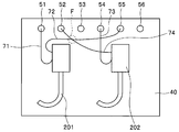
図8に示すように、内視鏡リプロセッサの洗浄槽40に、内視鏡が2本、内視鏡201、202として並列して収納される場合がある。
また、この場合、洗浄槽40には、2本の内視鏡201、202に対して同時に洗浄消毒処理を行うため内視鏡201、202の例えば吸引管路を兼ねた処置具挿通用管路に流体を供給するコネクタ51、54や、内視鏡201、202の例えば副送水管路に流体を供給するコネクタ52、55や、内視鏡201、202の漏水検知を行うため内視鏡201、202に気体を供給するコネクタ53、56が設けられている。
尚、図8に示すように、内視鏡201、202の各処置具挿通用管路は、洗浄チューブ71、73を介して、コネクタ51またはコネクタ54のどちらにも接続可能となっている。また、内視鏡201、202の各副送水管路は、洗浄チューブ72、74を介して、コネクタ52またはコネクタ55のどちらにも接続可能となっている。
よって、洗浄チューブ71、73は、コネクタ51、54のどちらにも接続できるように、洗浄チューブ72、74は、コネクタ52、55のどちらにも接続できるように、一定の長さを有している。
しかしながら、コネクタに対する洗浄チューブの選択を考慮すると、洗浄チューブ71~74に必要以上に長いものを用いなければならず、洗浄チューブが扱い難くなってしまうばかりか、例えば洗浄チューブ72をコネクタ55に接続し、洗浄チューブ74をコネクタ52に接続すると、図8の点線Fに示すように、洗浄チューブ72、74同士が重なる部位等も出てしまい、コネクタに対して洗浄チューブが接続し難くなってしまうといった問題がある。
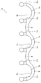
そこで、図9、図10に示すように、コネクタ51、52及びコネクタ54、55に装着される第1嵌合部1、第2嵌合部3、連結部5から構成された内視鏡リプロセッサ用コネクタ緩み止め具10’において、第1嵌合部1、第2嵌合部3の一面1a、3aに形成される一対の第1の溝1ma、1mbと、一対の第2の溝3ma、3mbとにおいて、第1嵌合部1と第2嵌合部3とをつなぐ軸Jに対し、第1の溝1maの最短距離y1と第1の溝1mbの最短距離y2とを異ならせた。さらに、第2の溝3maの最短距離y3と、第2の溝3mbの最短距離y4とを異ならせた。言い換えれば、第1の溝1ma、1mbと、第2の溝3ma、3mbとを、軸Jに対して傾けて形成した。
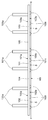
このような構成によれば、図9に示す内視鏡リプロセッサ用コネクタ緩み止め具10’を、それぞれ図10に示すように、コネクタ51、52及びコネクタ54、55に装着し、コネクタ51の第1の溝1ma、1mbに洗浄チューブ71のロックレバーが嵌合し、コネクタ52の第2の溝3ma、3mbに洗浄チューブ72のロックレバーが嵌合し、また、コネクタ54の第1の溝1ma、1mbに洗浄チューブ73のロックレバーが嵌合し、コネクタ55の第2の溝3ma、3mbに洗浄チューブ74のロックレバーが嵌合した際、各第1の溝1ma、1mb及び第2の溝3ma、3mbに嵌合した各ロックレバーは、上述したように回転が規制され、各内視鏡リプロセッサ用コネクタ緩み止め具10’も回転が規制されていることから、各溝1ma、1mb、3ma、3mbの傾斜角度により、洗浄チューブ71、72は、内視鏡201側に引き出され、洗浄チューブ73、74は、内視鏡202側に引き出される。
よって、洗浄チューブ71、72は、コネクタ51、52に接続しやすくなり、洗浄チューブ73、74は、コネクタ54、55に接続しやすくなる一方、洗浄チューブ71、72をコネクタ54、55に接続し難くなり、洗浄チューブ73、74を、コネクタ51、52に接続し難くなる。
即ち、洗浄チューブ71~74の取り付け位置を、第1の溝1ma、1mb、第2の溝3ma、3mbの傾きにより規定することができる。
よって、図8に示すように、洗浄チューブ同士が重なることも無く、また、必要以上に長い洗浄チューブを用いる必要がなくなるため、各コネクタ51、52、54、55に対する洗浄チューブ71~74の接続作業が行いやすくなる。
尚、第1の溝1ma、1mb、第2の溝3ma、3mbの傾き角度や、一面1a、3aに対する第1の溝1ma、1mb、第2の溝3ma、3mbの形成位置は、図9に限定されない。例えば溝は必ずしも一対である必要はなく、取り付ける洗浄チューブコネクタ31のロックレバー32の数に応じて、1つであってもよいし、3つ以上あってもよい。
また、その他の効果は、上述した本実施の形態と同じである。
(第2実施の形態)
図11は、本実施の形態の内視鏡リプロセッサ用コネクタ緩み止め具を示す斜視図、図12は、図11の内視鏡リプロセッサ用コネクタ緩み止め具を図11中のXII方向から見た斜視図である。
図11は、本実施の形態の内視鏡リプロセッサ用コネクタ緩み止め具を示す斜視図、図12は、図11の内視鏡リプロセッサ用コネクタ緩み止め具を図11中のXII方向から見た斜視図である。
また、図13は、図11の内視鏡リプロセッサ用コネクタ緩み止め具を、内視鏡リプロセッサにおける洗浄槽の第1コネクタ及び第2コネクタに装着した状態を示す部分斜視図、図14は、図13の内視鏡リプロセッサ用コネクタ緩み止め具を、洗浄槽とともに図13中のXIV方向からみた側面図、図15は、図13の洗浄槽の第1コネクタに、第1洗浄チューブコネクタが接続された状態を示す部分斜視図である。
この第2実施の形態の内視鏡リプロセッサ用コネクタ緩み止め具は、上述した第1実施の形態の内視鏡リプロセッサ用コネクタ緩み止め具と比して、第1の嵌合部及び第2の嵌合部の一面に壁部が形成されているとともに、洗浄槽のコネクタに外形が六角形の洗浄チューブコネクタが接続される点が異なる。
よって、この相違点のみを説明し、第1実施の形態と同様の構成には同じ符号を付し、その説明は省略する。
図11、図12に示すように、内視鏡リプロセッサ用コネクタ緩み止め具110は、第1嵌合部101と、第2嵌合部102、103と、第1嵌合部101と第2嵌合部102とをつなぐ連結部104と、第1嵌合部101と第2嵌合部103とをつなぐ連結部105とを具備して主要部が構成されている。
尚、本実施の形態においては、第2嵌合部が2つの場合を例に挙げて示しているが、これに限らず、第2嵌合部は1つであって良い。また、内視鏡リプロセッサ用コネクタ緩み止め具110は、例えば樹脂から形成されている。
第1嵌合部101は、第1嵌合溝101kを有するU字状に形成されており、図13に示すように、内視鏡リプロセッサ300(図18参照)の洗浄槽40の例えばテラス面40rtに設けられた第1コネクタ52に対して、嵌合溝101kが嵌合自在である。
第1コネクタ52は、図15に示すように、第1洗浄チューブ130の一端に設けられた、例えば六角形の外形を有する第1洗浄チューブコネクタ131が接続されることにより、第1洗浄チューブ130を介して、第1洗浄チューブ130の他端が接続された後述する内視鏡201(図18参照)の管路内に流体を供給するものであり、洗浄槽40のテラス面40rtに対して、例えばネジ固定されている。
尚、第1洗浄チューブコネクタ131の外形形状は、六角形に限定されず、角部を有する外形であれば良い。また、第1コネクタ52は、第1コネクタ52から第1洗浄チューブコネクタ131がワンタッチで外れる構造を有していても構わない。
図11に示すように、第1嵌合部101の表面である第1の面101a(以下、一面101aと称す)に、第1の壁部101wが形成されている。第1の壁部101wは、一面101aにおいて嵌合溝101kを挟んで対向するよう、例えば一対から構成されており、図15に示すように、第1コネクタ52に対して第1洗浄チューブコネクタ131が接続された際、第1洗浄チューブコネクタ131の外周面または外周面の角部に当接することにより、第1洗浄チューブコネクタの回転を規制する。
また、図12に示すように、第1嵌合部101の一面101aとは反対側の表面である第2の面101b(以下、他面と称す)101bに、第1突起部101tが、例えば3つ設けられている。尚、第1突起部101tの個数は3つに限定されない。
第1突起部101tは、第1嵌合部101を第1コネクタ52に対して嵌合させた際、図14に示すように、他面101bをテラス面40rtから離間させることによって、隙間Sを発生させるものである。
このことにより、洗浄槽40に供給される薬液が他面101bに接触可能となり、他面101bの洗浄消毒を行うことが可能になるとともに、隙間Sが十分確保できることにより、他面101bに薬液が残留してしまうことを防ぐことができる。
第2嵌合部102は、第2嵌合溝102kを有するU字状に形成されており、図13に示すように、洗浄槽40の例えばテラス面40rtにおいて第1コネクタ52に並んで設けられた第2コネクタ51に対して、第2嵌合溝102kが嵌合自在である。
尚、第1嵌合部101に連結部104を介してつながる第2嵌合部102が第2コネクタ51に嵌合されていることにより、内視鏡リプロセッサ用コネクタ緩み止め具110の回転が規制されている。
即ち、本実施の形態においては、第2嵌合部102及び連結部104は、第1嵌合部101から延出された第1嵌合部101の回転を規制する回転規制部となっている。さらに、第1嵌合部101及び連結部104は、第2嵌合部102の回転を規制している。
第2コネクタ51は、図示しない第2洗浄チューブAの一端に設けられた、例えば六角形の外形を有する図示しない第2洗浄チューブコネクタCが接続されることにより、第2洗浄チューブAを介して、第2洗浄チューブAの他端が接続された後述する内視鏡201(図18参照)の管路内に流体を供給するものであり、洗浄槽40のテラス面40rtに対して、例えばネジ固定されている。
尚、第2洗浄チューブコネクタCの外形形状は、六角形に限定されず、角部を有する外形形状であれば良い。また、第2コネクタ51は、第2コネクタ51から第2洗浄チューブコネクタCがワンタッチで外れる構造を有していても構わない。
図11に示すように、第2嵌合部102の表面である第1の面102a(以下、一面102aと称す)に、第2の壁部102wが形成されている。
第2の壁部102wは、一面102aにおいて嵌合溝102kを挟んで対向するよう、例えば一対から構成されており、第2コネクタ51に対して第2洗浄チューブコネクタCが接続された際、第2洗浄チューブコネクタCの外周面または外周面の角部に当接することにより、第2洗浄チューブコネクタCの回転を規制する。
また、図12に示すように、第2嵌合部102の一面102aとは反対側の表面である第2の面102b(以下、他面102bと称す)に、第2突起部102tが、例えば3つ設けられている。尚、第2突起部102tの個数は3つに限定されない。
第2突起部102tは、第2嵌合部102を第1コネクタ51に対して嵌合させた際、図14に示すように、他面102bをテラス面40rtから離間させることによって、隙間Sを発生させるものである。
このことにより、洗浄槽40に供給される薬液が他面102bに接触可能となり、他面102bの洗浄消毒を行うことが可能になるとともに、隙間Sが十分確保できることにより、他面102bに薬液が残留してしまうことを防ぐことができる。
第2嵌合部103は、第2嵌合溝103kを有するU字状に形成されており、図13に示すように、洗浄槽40の例えばテラス面40rtにおいて第1コネクタ52に並んで設けられた第2コネクタ53に対して、第2嵌合溝103kが嵌合自在である。
尚、第1嵌合部101に連結部105を介してつながる第2嵌合部103が第2コネクタ53に嵌合されていることにより、内視鏡リプロセッサ用コネクタ緩み止め具110の回転が規制されている。
即ち、本実施の形態においては、第2嵌合部103及び連結部105は、第1嵌合部101から延出された第1嵌合部101の回転を規制する回転規制部となっている。さらに、第1嵌合部101及び連結部105は、第2嵌合部103の回転を規制している。
第2コネクタ53は、図示しない第2洗浄チューブBの一端に設けられた、例えば六角形の外形を有する図示しない第2洗浄チューブコネクタDが接続されることにより、第2洗浄チューブBを介して、第2洗浄チューブBの他端が接続された後述する内視鏡201(図18参照)の管路内に流体を供給するものであり、洗浄槽40のテラス面40rtに対して、例えばネジ固定されている。
尚、第2洗浄チューブコネクタDの外形形状は、六角形に限定されず、角部を有する外形形状であれば良い。また、第2コネクタ53は、第3コネクタ53から第2洗浄チューブコネクタDがワンタッチで外れる構造を有していても構わない。
図11に示すように、第2嵌合部103の表面である第1の面103a(以下、一面103aと称す)に、第2の壁部103wが形成されている。
第2の壁部103wは、一面103aにおいて嵌合溝103kを挟んで対向するよう、例えば一対から構成されており、第2コネクタ53に対して第2洗浄チューブコネクタDが接続された際、第2洗浄チューブコネクタDの外周面または外周面の角部に当接することにより、第2洗浄チューブコネクタDの回転を規制する。
また、図12に示すように、第2嵌合部103の一面103aとは反対側の表面である第2の面103b(以下、他面103bと称す)に、第2突起部103tが、例えば3つ設けられている。尚、第2突起部103tの個数は3つに限定されない。
第2突起部103tは、第2嵌合部103を第1コネクタ53に対して嵌合させた際、図14に示すように、他面103bをテラス面40rtから離間させることによって、隙間Sを発生させるものである。
このことにより、洗浄槽40に供給される薬液が他面103bに接触可能となり、他面103bの洗浄消毒を行うことが可能になるとともに、隙間Sが十分確保できることにより、他面103bに薬液が残留してしまうことを防ぐことができる。
尚、第1コネクタ52、第2コネクタ51、53に対する内視鏡リプロセッサ用コネクタ緩み止め具110の第1嵌合部101、第2嵌合部102、103の嵌合は、第1コネクタ52、第2コネクタ51、53に対して第1洗浄チューブコネクタ131、第2洗浄チューブコネクタC、Dが接続された後に行っても構わないし、第1コネクタ52、第2コネクタ51、53に対して第1洗浄チューブコネクタ131、第2洗浄チューブコネクタC、Dが接続される前に行っても構わない。
このように、本実施の形態においては、洗浄槽40の第1コネクタ52、第2コネクタ51、53に対して、内視鏡リプロセッサ用コネクタ緩み止め具110においてそれぞれ連結部104、105によって連結された第1嵌合部101、第2嵌合部102、103が嵌合自在であると示した。
また、第1嵌合部101の第1の壁部101wは、第1コネクタ52に第1洗浄チューブコネクタ31が接続された際、第1洗浄チューブコネクタ31の回転を規制し、第2嵌合部102の第2の壁部102wは、第2コネクタ51に第2洗浄チューブコネクタCが接続された際、第2洗浄チューブコネクタCの回転を規制し、第2嵌合部103の第1の壁部103wは、第2コネクタ53に第2洗浄チューブコネクタDが接続された際、第2洗浄チューブコネクタDの回転を規制すると示した。
このことによれば、既存の内視鏡リプロセッサ300の洗浄槽40に設けられた各コネクタ51~53に内視鏡リプロセッサ用コネクタ緩み止め具110の各嵌合部101~103を装着するのみの簡単な構成によって、第1の壁部101wにより、第1洗浄チューブコネクタ131の回転を防ぐことができるとともに、第2の壁部102w、103wにより、第2洗浄チューブコネクタC、Dの回転を防ぐことができる。
また、第1コネクタ52に嵌合される第1嵌合部101、第2コネクタ51、53に嵌合される第2嵌合部102、103は、連結部104、105を介してそれぞれにつながれていることから、内視鏡リプロセッサ用コネクタ緩み止め具110が回転してしまうことを防ぐことができる。
よって、各コネクタ51~53に対する洗浄チューブコネクタの接続、回転に伴い、各コネクタ51~53が回転してしまうことを防ぐことができるため、洗浄槽40に対する各コネクタ51~53の固定が各コネクタ51~53の回転に起因して緩んでしまうことを、内視鏡リプロセッサ用コネクタ緩み止め具110によって防ぐことができる。
さらに、各コネクタ51~53に対する各嵌合部101~103の着脱は、各嵌合溝101k~103kを介して容易に行うことができるため、内視鏡リプロセッサ300の組み立て性及びメンテナンス性が向上する。
以上から、本実施の形態においても、上述した第1実施の形態と同様の効果を得ることができる。
尚、以下、変形例を、図16を用いて示す。図16は、図13の洗浄槽のコネクタに内視鏡リプロセッサ用コネクタ緩み止め具の回転規制形状を設けた変形例を示す斜視図である。
図16に示すように、各コネクタ51~53に、内視鏡リプロセッサ用コネクタ緩み止め具110の各嵌合部101~103が装着された際、壁部101w~103wが当接することにより、各コネクタ51~53に対する内視鏡リプロセッサ用コネクタ緩み止め具110の回転を規制する回転規制形状50dが形成されていても構わない。尚、回転規制形状50dとしては、例えば既知のDカット形状が挙げられる。
このような構成によっても、上述した本実施の形態と同様の効果を得ることができる。
また、以下、別の変形例を示す。
上述した本実施の形態においても、第1実施形態の図7と同様に、内視鏡リプロセッサ用コネクタ緩み止め具110は、第1嵌合部101及び該第1嵌合部101から延出された回転規制部となる延出部のみから構成されていても構わない。
このような構成によっても、上述した本実施の形態と同様の効果を得ることができる。
また、上述した本実施の形態においては、内視鏡リプロセッサ用コネクタ緩み止め具110は、3つの嵌合部101~103を有していると示した。これに限らず、上述したように嵌合部の全体数は1つでも良ければ、第2の嵌合部が1つの場合は、嵌合部の全体数は2つでも良いし、洗浄槽40に設けられるコネクタの数に応じて全体数は4つ以上であっても良いことは勿論である。
さらに、以下、別の変形例を示す。
上述した本実施の形態においても、第1実施の形態の図8~図10と同様に、各壁部101w~103wは、軸Jに対して傾けて設けられていても構わない。
このことによっても、洗浄チューブ71~74の取り付け位置を、各壁部の傾きにより規定することができる。
また、以下、上述した第1実施の形態の内視鏡リプロセッサ用コネクタ緩み止め具10及び第2実施の形態の内視鏡リプロセッサ用コネクタ緩み止め具110が取り付く内視鏡リプロセッサの一例を、図17、図18を用いて示す。尚、内視鏡リプロセッサは、内視鏡洗浄消毒装置を例に挙げて示す。
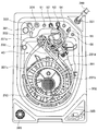
図17は、内視鏡洗浄消毒装置の一例を、トップカバーが開放され、洗浄槽に内視鏡が収納自在な状態において示す内視鏡洗浄消毒装置の斜視図、図18は、図17の洗浄槽に内視鏡が収容され、内視鏡と洗浄槽のコネクタとが洗浄チューブによって接続された状態を示す斜視図である。
図17に示すように、内視鏡洗浄消毒装置300は、使用済みの内視鏡201を洗浄、消毒するための装置であり、装置本体302と、その上部に、例えば図示しない蝶番を介して開閉自在に接続されたトップカバー303とにより、主要部が構成されている。
トップカバー303が、装置本体302に閉じられている状態では、装置本体302とトップカバー303とは、装置本体302及びトップカバー303の互いに対向する位置に配設された、例えばラッチ308により固定される構成となっている。
装置本体302の操作者が近接する図中前面であって、例えば左半部の上部に、洗剤/アルコールトレー311が、装置本体302の前方へ引き出し自在に配設されている。
洗剤/アルコールトレー311には、内視鏡201を洗浄する際に用いられる液体である洗浄剤が貯留された洗剤タンク311aと、洗浄消毒後の内視鏡201を乾燥する際に用いられる液体であるアルコールが貯留されたアルコールタンク311bとが収納されており、洗剤/アルコールトレー311が引き出し自在なことにより、各タンク311a、311bに、所定に液体が補充できるようになっている。
尚、洗剤/アルコールトレー311には、2つの窓部311mが設けられており、該窓部311mにより、各タンク311a、311bに注入されている洗浄剤及びアルコールの残量が操作者によって確認できるようになっている。
また、装置本体302の前面であって、例えば右半部の上部に、消毒液トレー312が、装置本体302の前方へ引き出し自在に配設されている。消毒液トレー312には、内視鏡201を消毒する際に用いる、例えば過酢酸等の消毒液が注入された2つの薬液ボトル312a、312bが収納されており、消毒液トレー312が、引き出し自在なことにより2つの薬液ボトル312a、312bを所定にセットできるようになっている。
尚、消毒液トレー312には、2つの窓部312mが設けられており、該窓部312mにより、各薬液ボトル312a、312bに注入されている消毒液の残量が操作者によって確認できるようになっている。
さらに、装置本体302の前面であって、消毒液トレー312の上部に、洗浄消毒時間の表示や、消毒液を加温するための指示釦等が配設されたサブ操作パネル313が配設されている。
また、装置本体302の図中前面の下部に、装置本体302の上部に閉じられているトップカバー303を、操作者の踏み込み操作により装置本体302の上方に開くためのペダルスイッチ304が配設されている。
また、図17、図18に示すように、装置本体302の上面の、例えば操作者が近接する前面側の右端寄りに、装置本体302の洗浄、消毒動作スタートスイッチ、及び洗浄、消毒モード選択スイッチ等の設定スイッチ類が配設されたメイン操作パネル325が設けられているとともに、操作者が近接する前面側の左端寄りに、近付けられた内視鏡201から情報を受け取る、例えばRFIDから構成された受信部365が設けられている。
また、装置本体302の上面であって、操作者が近接する前面に対向する背面側に、装置本体302に水道水を供給するための水道蛇口に接続された給水ホース399が接続される給水ホース接続口331が配設されている。
尚、給水ホース接続口331に、水道水を濾過するメッシュフィルタが配設されていてもよい。
さらに、装置本体302の上面の略中央部に、内視鏡収納口をトップカバー303によって開閉される、内視鏡201が収納自在な洗浄槽40が設けられている。
洗浄槽40は、操作者が近接する前面側に位置する第1の槽本体40tと、第1の槽本体40tよりも底面が低く位置しているとともに第1の槽本体40tよりも背面側に位置する第2の槽本体40dと、第1の槽本体40t及び第2の槽本体40dの内視鏡収納口の外周縁に連続して周設されたテラス部40rとにより構成されている。
第1の槽本体40t及び第2の槽本体40dは、内視鏡201が洗浄消毒される際、該内視鏡201が収納自在である。
尚、図18に示すように、第1の槽本体40tには、内視鏡201の挿入部201b及びユニバーサルコード201cが巻回されて収納され、第2の槽本体40dには、内視鏡201の操作部201a、コネクタ201dが収納される。
第2の槽本体40dの底面には、第1の槽本体40t及び第2の槽本体40dに供給された洗浄液、水、アルコール、消毒液等を第1の槽本体40t及び第2の槽本体40dから排水するための排水口355が設けられているともに、第1の槽本体40t及び第2の槽本体40dに供給された洗浄液、水、消毒液等を、内視鏡201の内部に具備された各管路に供給する、またはメッシュフィルタ等を介し、後述する給水循環ノズル324から第1の槽本体40t及び第2の槽本体40dに再度上記液体を供給するための循環口356が設けられている。尚、循環口356には、洗浄液等を濾過するメッシュフィルタが設けられていても良い。
第2の槽本体40dの側面の任意の位置に、第1の槽本体40t及び第2の槽本体40dに供給された洗浄液、水、消毒液等の水位を検出するカバー付き水位センサ332が設けられている。
テラス部40rのテラス面40rtに、第1の槽本体40t及び第2の槽本体40dに対し、洗剤タンク311aから水道水により所定の濃度に希釈される洗浄剤を供給するための洗剤ノズル322及び消毒液を供給するための消毒液ノズル323が設けられている。
また、テラス面40rtに、第1の槽本体40t及び第2の槽本体40dに対し給水するための、または循環口356から吸引した洗浄液、水、消毒液等を、再度第1の槽本体40t及び第2の槽本体40dに供給するための給水循環ノズル324と、第1の槽本体40t及び第2の槽本体40dに供給された洗浄液、水、消毒液等の異常水位を検知するフロートスイッチ391とが設けられている。
さらに、テラス面40rtに、内視鏡201の内部に具備された各種管路に、洗浄液、水、アルコール、消毒液、またはエア等を、洗浄チューブを介して供給するためのコネクタ51~54と、内視鏡201の漏水検知用コネクタ55、56とが設けられている。
尚、上述した内視鏡洗浄消毒装置の構成は、あくまでも一例であり、この限りではない。また、内視鏡リプロセッサは、内視鏡洗浄消毒装置に限定されず、滅菌装置等にも適用可能である。
本出願は、2014年7月17日に日本国に出願された特願2014-147068号を優先権主張の基礎として出願するものであり、上記の内容は、本願明細書、請求の範囲、図面に引用されたものである。
Claims (12)
- 内視鏡リプロセッサの洗浄槽に配置された第1コネクタに嵌合自在な溝である第1嵌合溝を含む第1嵌合部と、
前記第1コネクタに接続された第1洗浄チューブコネクタのロックレバーが嵌合される、前記第1嵌合部の表面に形成された少なくとも1つの第1の溝と、
前記第1嵌合部から延出された、前記第1嵌合部の回転を規制する回転規制部と、
を備えていることを特徴とする内視鏡リプロセッサ用コネクタ緩み止め具。 - 前記回転規制部は、
前記洗浄槽において前記第1コネクタに並んで配置された第2コネクタに嵌合自在な溝である第2嵌合溝を含む第2嵌合部と、
前記第1嵌合部と前記第2の嵌合部とをつなぐ連結部と、
を備えていることを特徴とする請求項1に記載の内視鏡リプロセッサ用コネクタ緩み止め具。 - 前記第2嵌合部は、
前記第2コネクタに接続された第2洗浄チューブコネクタのロックレバーが嵌合される、前記第2嵌合部の表面に形成された少なくとも1つの第2の溝を備えていることを特徴とする請求項2に記載の内視鏡リプロセッサ用コネクタ緩み止め具。 - 前記第1嵌合部と前記第2嵌合部とをつなぐ軸に対して、前記第1の溝と前記第2の溝とで最短距離が異なっていることを特徴とする請求項3に記載の内視鏡リプロセッサ用コネクタ緩み止め具。
- 前記第1嵌合部は、前記第1の溝が形成された第1の面と、前記第1の面に対して交差または対向する第2の面を有し、
前記第2の面には、第1突起部が設けられていることを特徴とする請求項1に記載の内視鏡リプロセッサ用コネクタ緩み止め具。 - 前記第2嵌合部は、前記第1の溝が形成された第1の面と、前記第1の面に対して交差または対向する第2の面を有し、
前記第2の面に、第2突起部が設けられていることを特徴とする請求項3に記載の内視鏡リプロセッサ用コネクタ緩み止め具。 - 内視鏡リプロセッサの洗浄槽に配置された第1コネクタに対して嵌合自在な溝である第1嵌合溝を含む第1嵌合部と、
前記第1コネクタに接続された第1洗浄チューブコネクタの回転を規制する、前記第1嵌合部の表面から起立する少なくとも1つの第1の壁部と、
前記第1嵌合部から延出された、前記第1嵌合部の回転を規制する回転規制部と、
を備えていることを特徴とする内視鏡リプロセッサ用コネクタ緩み止め具。 - 前記回転規制部は、
前記洗浄槽において前記第1コネクタに並んで配置された第2コネクタ嵌合自在な溝である第2嵌合溝を含む第2嵌合部と、
前記第1嵌合部と前記第2の嵌合部とをつなぐ連結部と、
を備えていることを特徴とする請求項7に記載の内視鏡リプロセッサ用コネクタ緩み止め具。 - 前記第2コネクタに接続された第2洗浄チューブコネクタの回転を規制する、前記第2嵌合部の表面から起立する少なくとも1つの第2の壁部をさらに備えていることを特徴とする請求項8に記載の内視鏡リプロセッサ用コネクタ緩み止め具。
- 前記第1嵌合部と前記第2嵌合部とをつなぐ軸に対して、前記第1の壁部と前記第2の壁部とで最短距離が異なっていることを特徴とする請求項9に記載の内視鏡リプロセッサ用コネクタ緩み止め具。
- 前記第1嵌合部は、前記第1の溝が形成された第1の面と、前記第1の面に対して交差または対向する第2の面を有し、
前記第2の面に、第1突起部が設けられていることを特徴とする請求項7に記載の内視鏡リプロセッサ用コネクタ緩み止め具。 - 前記第1嵌合部は、前記第1の溝が形成された第1の面と、前記第1の面に対して交差または対向する第2の面を有し、
前記第2の面に、第2突起部が設けられていることを特徴とする請求項9に記載の内視鏡リプロセッサ用コネクタ緩み止め具。
Priority Applications (1)
| Application Number | Priority Date | Filing Date | Title |
|---|---|---|---|
| JP2015532237A JPWO2016009677A1 (ja) | 2014-07-17 | 2015-03-17 | 内視鏡リプロセッサ用コネクタ緩み止め具 |
Applications Claiming Priority (2)
| Application Number | Priority Date | Filing Date | Title |
|---|---|---|---|
| JP2014-147068 | 2014-07-17 | ||
| JP2014147068 | 2014-07-17 |
Publications (1)
| Publication Number | Publication Date |
|---|---|
| WO2016009677A1 true WO2016009677A1 (ja) | 2016-01-21 |
Family
ID=55078182
Family Applications (1)
| Application Number | Title | Priority Date | Filing Date |
|---|---|---|---|
| PCT/JP2015/057909 Ceased WO2016009677A1 (ja) | 2014-07-17 | 2015-03-17 | 内視鏡リプロセッサ用コネクタ緩み止め具 |
Country Status (2)
| Country | Link |
|---|---|
| JP (1) | JPWO2016009677A1 (ja) |
| WO (1) | WO2016009677A1 (ja) |
Citations (5)
| Publication number | Priority date | Publication date | Assignee | Title |
|---|---|---|---|---|
| JPS6111085A (ja) * | 1984-03-14 | 1986-01-18 | 川人 克昌 | 定電圧蓄電器装置 |
| JPH09264456A (ja) * | 1996-03-28 | 1997-10-07 | Tokai Rubber Ind Ltd | 配管取付装置 |
| JP2003207073A (ja) * | 2002-01-11 | 2003-07-25 | Yamaha Livingtec Corp | 配管接続用アダプターの共回り防止構造及び共回り防止部材 |
| JP2006038033A (ja) * | 2004-07-23 | 2006-02-09 | Toyota Motor Corp | 配管接続構造及び配管接続構造用クリップ |
| JP2013135843A (ja) * | 2011-12-01 | 2013-07-11 | Fujifilm Corp | 内視鏡用洗浄アダプタ |
Family Cites Families (1)
| Publication number | Priority date | Publication date | Assignee | Title |
|---|---|---|---|---|
| JPS6111085U (ja) * | 1984-06-25 | 1986-01-22 | シ−ケ−デイ株式会社 | 流体注入用接続装置 |
-
2015
- 2015-03-17 WO PCT/JP2015/057909 patent/WO2016009677A1/ja not_active Ceased
- 2015-03-17 JP JP2015532237A patent/JPWO2016009677A1/ja active Pending
Patent Citations (5)
| Publication number | Priority date | Publication date | Assignee | Title |
|---|---|---|---|---|
| JPS6111085A (ja) * | 1984-03-14 | 1986-01-18 | 川人 克昌 | 定電圧蓄電器装置 |
| JPH09264456A (ja) * | 1996-03-28 | 1997-10-07 | Tokai Rubber Ind Ltd | 配管取付装置 |
| JP2003207073A (ja) * | 2002-01-11 | 2003-07-25 | Yamaha Livingtec Corp | 配管接続用アダプターの共回り防止構造及び共回り防止部材 |
| JP2006038033A (ja) * | 2004-07-23 | 2006-02-09 | Toyota Motor Corp | 配管接続構造及び配管接続構造用クリップ |
| JP2013135843A (ja) * | 2011-12-01 | 2013-07-11 | Fujifilm Corp | 内視鏡用洗浄アダプタ |
Also Published As
| Publication number | Publication date |
|---|---|
| JPWO2016009677A1 (ja) | 2017-04-27 |
Similar Documents
| Publication | Publication Date | Title |
|---|---|---|
| US7758704B2 (en) | Endoscope cleaning/disinfecting apparatus | |
| JP6188579B2 (ja) | 洗浄装置 | |
| JP5676057B1 (ja) | 内視鏡接続具及び内視鏡洗浄消毒装置 | |
| US8366834B2 (en) | Endoscope cleaning/disinfecting apparatus | |
| US9233181B2 (en) | Endoscope cleaning/disinfecting apparatus | |
| JP4975195B2 (ja) | 内視鏡洗浄消毒装置連結具、内視鏡洗浄消毒システム | |
| JP6203100B2 (ja) | 内視鏡洗浄アタッチメント | |
| US20160309989A1 (en) | Endoscope connector and endoscope reprocessor | |
| WO2012017720A1 (ja) | 内視鏡洗浄消毒装置連結具、内視鏡洗浄消毒装置 | |
| JP6230765B1 (ja) | 内視鏡再生処理具 | |
| JP5231027B2 (ja) | 内視鏡洗浄消毒装置 | |
| WO2016009677A1 (ja) | 内視鏡リプロセッサ用コネクタ緩み止め具 | |
| JPH04317623A (ja) | 内視鏡洗浄消毒装置 | |
| JP5120779B2 (ja) | 圧送移動式便器 | |
| JP5014954B2 (ja) | 内視鏡洗浄消毒装置 | |
| JP6367094B2 (ja) | 水栓 | |
| JP6010272B1 (ja) | 内視鏡リプロセッサ | |
| JP6444703B2 (ja) | 水栓 | |
| JP5029267B2 (ja) | 洗浄水タンク装置 | |
| JP2010057560A (ja) | 洗浄消毒装置 | |
| WO2019035249A1 (ja) | 内視鏡リプロセッサ |
Legal Events
| Date | Code | Title | Description |
|---|---|---|---|
| ENP | Entry into the national phase |
Ref document number: 2015532237 Country of ref document: JP Kind code of ref document: A |
|
| 121 | Ep: the epo has been informed by wipo that ep was designated in this application |
Ref document number: 15822708 Country of ref document: EP Kind code of ref document: A1 |
|
| NENP | Non-entry into the national phase |
Ref country code: DE |
|
| 122 | Ep: pct application non-entry in european phase |
Ref document number: 15822708 Country of ref document: EP Kind code of ref document: A1 |