WO2016010091A1 - 縫目構造 - Google Patents
縫目構造 Download PDFInfo
- Publication number
- WO2016010091A1 WO2016010091A1 PCT/JP2015/070316 JP2015070316W WO2016010091A1 WO 2016010091 A1 WO2016010091 A1 WO 2016010091A1 JP 2015070316 W JP2015070316 W JP 2015070316W WO 2016010091 A1 WO2016010091 A1 WO 2016010091A1
- Authority
- WO
- WIPO (PCT)
- Prior art keywords
- stitch
- fabric
- thread
- tape
- seam
- Prior art date
- Legal status (The legal status is an assumption and is not a legal conclusion. Google has not performed a legal analysis and makes no representation as to the accuracy of the status listed.)
- Ceased
Links
Images







Classifications
-
- A—HUMAN NECESSITIES
- A41—WEARING APPAREL
- A41D—OUTERWEAR; PROTECTIVE GARMENTS; ACCESSORIES
- A41D27/00—Details of garments or of their making
- A41D27/24—Hems; Seams
-
- D—TEXTILES; PAPER
- D05—SEWING; EMBROIDERING; TUFTING
- D05B—SEWING
- D05B1/00—General types of sewing apparatus or machines without mechanism for lateral movement of the needle or the work or both
- D05B1/08—General types of sewing apparatus or machines without mechanism for lateral movement of the needle or the work or both for making multi-thread seams
- D05B1/10—Double chain-stitch seams
-
- D—TEXTILES; PAPER
- D05—SEWING; EMBROIDERING; TUFTING
- D05B—SEWING
- D05B93/00—Stitches; Stitch seams
Definitions
- This disclosure relates to a stitch structure.
- a flat seamer is, for example, a sewing machine that uses four needles, has four stitches, four needle threads, one lower thread, and one upper decoration thread, and has a flat seam. It is a method (for example, refer patent document 1, patent document 2).
- the sewing machine for a flat seam is a flat seam sewing machine, and a seam formed by the flat seam is called a flat seam.
- the sewn portion is stitched in a state where the fabric ends are butted together, so that the sewing portion is soft and there are few irregularities.
- clothes sewn with a flat seamer do not have a seam allowance on the back side of the fabric, so that the seam allowance is not applied to the skin and the stress on the skin is reduced. That is, it provides a good comfort for the wearer.
- the flat seamer is easier to cope with the elongation of the fabric than the ordinary sewing method, and the strength and durability of the sewing portion are very excellent. For this reason, flat seamers are widely used in sportswear such as underwear, swimwear, various sports uniforms, and wet suits.
- an object of the present disclosure is to provide a seam structure with less skin contact and excellent quality.
- the present disclosure is a first fabric having a first end and a second fabric having a second end, and the direction in which the second end extends is substantially parallel to the direction in which the first end extends.
- the second fabric is disposed by being adjacent to the first fabric, the first thread, the first stitch extending in the direction substantially parallel to the direction in which the first end extends, and the second thread.
- a second seam extending in a direction substantially parallel to the direction in which the second end extends, a third seam formed by a decorative thread, and a tape-like member having a base and an adhesive portion, and a first surface
- a second seam structure wherein the first thread is arranged so that at least the first fabric reciprocates and penetrates in the thickness direction at the first seam.
- the second thread is arranged so as to pass through at least the second fabric repeatedly reciprocating in its thickness direction.
- a third seam is disposed on the first surface, and at the third seam, the decorative thread is disposed so as to repeatedly span at least the first thread and the second thread, and the tape
- the seam structure is characterized in that the first member is disposed on the second surface, and the adhesive portion of the tape-like member bonds the first fabric and the second fabric.
- the stitch structure of the present disclosure has little skin contact and is excellent in quality.
- FIG. 1 is a schematic cross-sectional view of a stitch structure 1 according to the first embodiment of the present disclosure.
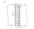
- FIG. 2 is a schematic plan view of the first surface 2 of the stitch structure 1 according to the first embodiment of the present disclosure.
- FIG. 3 is a schematic plan view of the second surface 3 of the stitch structure 1 according to the first embodiment of the present disclosure.
- FIG. 4 is a perspective view illustrating an example of a sewing machine used to form the stitch structure of the present disclosure.
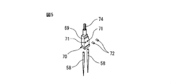
- FIG. 5 is an exploded perspective view showing a needle basket and each needle in the sewing machine shown in FIG.
- FIG. 6 is a perspective view showing movement paths of the needle and the lower looper.
- FIG. 7 is a diagram schematically showing how two fabrics are stitched together using the sewing machine shown in FIG. FIG.
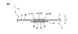
- FIG. 8 is a schematic cross-sectional view of a stitch structure according to the second embodiment of the present disclosure.
- FIG. 9 is a schematic cross-sectional view of a stitch structure according to the third embodiment of the present disclosure.
- FIG. 10 is a schematic cross-sectional view of a stitch structure according to the fourth embodiment of the present disclosure.
- FIG. 1 is a cross-sectional view
- FIG. 2 is a plan view of a first surface 2 of the stitch structure 1.
- FIG. 1 is a cross-sectional view
- FIG. 2 is a plan view of a first surface 2 of the stitch structure 1.
- the stitch structure 1 of the present disclosure is formed by a first fabric 4 having a first end 4a, a second fabric 5 having a second end 5a, and a first thread T1, and the first end 4a extends.
- a first stitch 11 extending in a direction substantially parallel to the direction D and a second thread T2
- a second stitch 12 extending in a direction substantially parallel to the direction D in which the second end 5a extends, and a decorative thread T3
- a tape-like member 14 having a base portion and an adhesive portion, and has a first surface 2 and a second surface 3.
- the first seam 11 and the second seam 12 are disposed so as to extend in a substantially parallel direction (direction D) with a certain width W therebetween.
- the first fabric 4 and the second fabric 5 are adjacent so that the direction in which the first end 4a extends and the direction in which the second end 5a extends extend in a substantially parallel direction (direction D). Are arranged.
- the first fabric 4 and the second fabric 5 are arranged in a state where the first end 4 a and the second end 5 a overlap in the thickness direction T of the stitch structure 1.
- the first thread T ⁇ b> 1 is disposed so as to repeatedly reciprocate in the thickness direction T of the first fabric 4 and the tape-shaped member 14 through the first fabric 4 and the tape-shaped member 14. Yes.
- the first thread T ⁇ b> 1 is on the second surface 3 side of the stitch structure 1 of the surface 4 b of the first fabric 4 on the first surface 2 side of the stitch structure 1 and the tape-like member 14. It is reciprocating repeatedly between the surface 14a.
- the second thread T2 is arranged so as to repeatedly reciprocate through the second fabric 5 and the tape-like member 14 in the thickness direction T of the second fabric 5 and the tape-like member 14.
- the second thread T ⁇ b> 2 is a surface 4 b of the first fabric 4 on the first surface 2 side of the seam structure 1 and a tape-like member 14 on the second surface 3 side of the seam structure 1. It is reciprocating repeatedly between the surface 14a.
- the third seam 13 is disposed on the first surface 2 side of the seam structure 1, and at the third seam 13, the decorative thread T3 is repeatedly stretched between the first thread T1 and the second thread T2. Has been placed.
- the third stitch 13 meanders between the first thread T1 and the second thread T2.
- the tape-shaped member 14 is disposed on the second surface 3 side, and the adhesive portion of the tape-shaped member 14 bonds the first fabric 4 and the second fabric 5.
- the end surface 4 c of the first end 4 a of the first fabric 4 and the end surface 5 c of the second end 5 a of the second fabric 5 are between the first stitch 11 and the second stitch 12. Exists.
- the wearer is less likely to feel the skin.
- the 2nd surface 3 since the junction part of the 1st fabric 4 and the 2nd fabric 5 is covered with the tape-shaped member 14, it is excellent in quality.
- the end surface 4 c of the first end 4 a of the first fabric 4 and the end surface 5 c of the second end 5 a of the second fabric 5 include the first stitch 11 and the first stitch 4.
- at least the end surface of the first end portion of the first fabric is present between the first stitch and the second stitch, so that the end surface of the first end portion exists. Is covered with the third seam (decoration thread) and cannot be directly visually recognized from the outside, so that it is excellent in quality such as beauty.
- the end surface of the second end portion of the second fabric may not exist between the first stitch and the second stitch.
- the end surface 5 c of the second end 5 a of the second fabric 5 exists between the first seam 11 and the second seam 12.
- the end surface of the second end portion of the second fabric exists on the outer side of the first stitch (on the side opposite to the second stitch). If the tape-like member adheres the first fabric and the second fabric, that is, covers the end surface of the second end of the second fabric, the problem of touch caused by the end surface of the second end is unlikely to occur. Because. Further, since the end surface of the second end portion of the second fabric exists outside the first stitch, the first stitch repeatedly reciprocates at least the first fabric and the second fabric in the thickness direction. Since it arrange
- the first thread T1 repeatedly reciprocates in the thickness direction T through the first fabric 4 and the tape-like member 14.
- the strength of the seam structure is increased by arranging the first seam so as to repeatedly reciprocate and penetrate the member including the tape-like member in the thickness direction thereof. Become.
- the strength of the seam structure is increased by arranging the member including the tape-like member so as to reciprocate and penetrate in the thickness direction.
- the first fabric and the second fabric are not particularly limited, and include fabrics that are usually used in the art, such as woven fabrics, knitted fabrics, and nonwoven fabrics.
- the yarns such as the first yarn, the second yarn, and the decorative yarn (and the third yarn and the fourth yarn described later) include those commonly used in the art, for example, for flat seams.
- the first fabric And the thing which is easy to extend is preferable so that the elongation of a 2nd fabric may not be inhibited.
- the base of the tape-shaped member is not particularly limited, and examples thereof include fabrics such as woven fabrics, knitted fabrics, and non-woven fabrics. Preferably there is. Further, when the base portion of the tape-shaped member is a knitted fabric and the first stitch and the second stitch are exposed on the surface of the tape-shaped member, the first stitch and the second stitch are configured, respectively. Since the 1st yarn and the 2nd yarn can sink into the base which is a knitted fabric, the touch nature of the 2nd surface improves.
- the thickness of the tape-shaped member is thinner than when it is a knitted fabric, but the first and second stitches are less likely to sink into the base and are worn. A person tends to feel the first and second stitches on the second surface, and the touch tends to decrease.
- a tape-shaped member As an adhesive part of a tape-shaped member, what is normally used in this technical field is mentioned, For example, what has adhesiveness at room temperature, what has adhesiveness by heating, etc. are mentioned.
- the tape-shaped member include a base having a polyester knitted fabric and a polyurethane hot melt adhesive. The said tape-shaped member adhere
- the tape-shaped member has a certain thickness also from the viewpoint described above.
- the thickness of the tape-shaped member is not particularly limited, but is preferably about 0.1 mm to 0.5 mm, for example.
- FIG. 4 is a perspective view showing an example of the sewing machine 50 used to form the stitch structure 1 of the present embodiment.
- This sewing machine 50 basically has the same configuration as a conventional four-needle flat seamer.
- the first two stitches and the second stitches are formed with two inner needle threads in a state where the two outer needles and needle threads of the four needles and the upper decoration thread are removed.
- the stitches and the decorative thread on the first surface are formed with the lower thread.
- the sewing machine 50 includes a sewing machine main body 52 fixed to the base 51 and a bed 53 provided to extend from the sewing machine main body 52.
- the sewing machine main body 52 is substantially L-shaped and has a rising portion 54 that rises upward from the base 51, a horizontal portion 55 that is bent at a substantially right angle from the upper end portion of the rising portion 54 and extends in the horizontal direction, A needle bar guide 56 provided at the tip of the horizontal portion 55.
- a needle bar 57 is accommodated in the needle bar guide 56 in a state where the needle bar 57 can reciprocate in the vertical direction and the upper end protrudes upward from the needle bar guide 56.
- the needle bar 57 receives power from a motor (not shown) provided in the base 51 and reciprocates in the vertical direction.
- Two needles 58 are provided at the lower end of the needle bar 57 below the needle bar guide 56. The two needles 58 move up and down as the needle bar 57 is driven to move up and down.
- the bed 53 extends in a substantially horizontal direction from the rising portion 54 of the sewing machine main body 52, and is arranged so that the tip thereof faces two needles 58 provided on the needle bar guide portion 56.
- a lower looper 61 is provided inside the bed 53 in the vicinity of the front end thereof, that is, at a position facing the lower side of the needle 58.
- the lower looper 61 moves in an elliptical orbit in synchronization with the vertical movement of the needle 58.
- Needle thread T11 is supplied to the two needles 58 from a thread winding reel (not shown) via a first thread guide piece 62, a second thread guide piece 63, and a third thread guide piece 64.
- each needle thread T11 is individually adjusted by a tension adjusting means 65 interposed between the first thread guide piece 62 and a thread winding reel (not shown).
- the decorative yarn T12 is supplied to the lower looper 61 through a tension adjusting means 68 from a thread winding reel (not shown) through the sewing machine main body 52. Thereby, the tension of the decorative thread T12 supplied to the lower looper 61 is easily adjusted.
- the tape-like member 14 faces the fabric cutter 90 that cuts the first end of the first fabric and the second end of the second fabric, and between the fabric cutter 90 and the needle 58. And a tape-like member supply means (not shown) for supplying.
- the tape-like member 14 is stacked on the first fabric and the second fabric through the guide hole 91.
- FIG. 5 is an exploded perspective view showing the needle basket 69 and the two needles 58.
- the needle basket 69 has a substantially rectangular cross section and has an insertion hole 70 into which the two needles 58 are inserted.
- the two needles 58 are inserted into the insertion hole 70, and the mounting bolt 72 is screwed into the screw hole 71 to be attached to the needle cage 69.
- the insertion hole 70 has a rectangular shape, and the two needles 58 are mounted side by side in the width direction of the needle basket 69.
- Two needles 58 are attached to the needle basket 69, and the needle basket 69 is screwed onto the needle bar 57 with a mounting portion 74 having an external thread formed on the side opposite to the side on which the two needles 58 are attached. By attaching, the two needles 58 are attached to the needle bar 57.
- FIG. 6 is a perspective view showing movement paths of the needle 58 and the lower looper 61 in the sewing machine 50.
- An insertion hole 81 is formed near the tip of the needle 58, and the needle thread T ⁇ b> 11 is inserted through the insertion hole 81.
- the needle 58 reciprocates up and down to form a first stitch (and a second stitch).
- the lower looper 61 is long and has a sharp tip 85.
- a decorative thread T12 is inserted through the lower looper 61 from the rear end 86 side to the vicinity of the front end 85.
- the decorative thread T12 is operated by the lower looper 61 to form the third stitch.
- the lower looper 61 is moved in an elliptical shape so as to surround the passage route of the needle 58 in a plane substantially perpendicular to the vertical direction of the needle 58. Such movement of the lower looper 61 on the elliptical orbit is performed in synchronization with the vertical movement of the needle 58.
- FIG. 7 is a diagram schematically illustrating a state in which two fabrics are stitched together using the sewing machine 50.
- the first fabric 4 and the second fabric 5 are arranged along the lap former 92 in a state where the first end 4a and the second end 5a are combined with the surface forming the second surface 3 facing upward. Enter the sewing machine 50.
- the fabric cutter 90 cuts a seam allowance portion (a part of the first end portion 4a) of the first fabric 4 and a seam allowance portion (a part of the second end portion 5a) of the second fabric 5.
- the tape-like member 14 is supplied between the fabric cutter 90 and the needle 58 through a guide hole 91 from a tape-like member supply unit (not shown). Appropriate tension is applied to the tape-like member 14 by tension adjusting means (not shown).
- the tape-shaped member 14 is disposed so as to cover the first end 4 a of the first fabric 4 and the second end 5 a of the second fabric 5.
- the first fabric 4, the second fabric 5, and the tape-shaped member 14 are sewn together by the two needle threads T11 that penetrate the tape-shaped member 14 in the thickness direction.
- the decorative thread T12 is engaged between the two needle threads T11 so that the two needle threads T11 are alternately routed.
- the portion including the tape-like member 14 is heated, and the tape-like member 14 is bonded to the first fabric 4 and the second fabric 5.
- the heating can be performed in a separate process from the sewing process by a hot press device provided separately from the sewing machine 50. Further, a heating press device can be provided immediately after the sewing machine 50, and the heating can be performed following the sewing process. The heating is performed by a method known in the art.
- FIG. 8 is a cross-sectional view schematically showing the stitch structure 1 of the present embodiment.
- the 1st fabric 4 and the 2nd fabric 5 are arrange
- the first thread T ⁇ b> 1 repeatedly reciprocates the first fabric 4 and the tape-shaped member 14 in the thickness direction T of the first fabric 4 and the tape-shaped member 14.
- the second thread T2 repeats the second fabric 5 and the tape-like member 14 in the thickness direction T of the second fabric 5 and the tape-like member 14 at the second stitch 12. It arrange
- the second surface 3 of the stitch structure 1 is used on the skin side of the wearer, but in the present embodiment, the thickness of the stitch structure can be reduced, The skin contact is improved when worn.
- FIG. 9 is a cross-sectional view schematically showing the stitch structure 1 of the present embodiment.
- the first thread T1 is disposed so as to repeatedly reciprocate through the first fabric 4 in the thickness direction T of the first fabric, and the second stitch.
- the second thread T2 is arranged so as to repeatedly reciprocate and penetrate the second fabric 5 in the thickness direction T of the second fabric 5.
- the first seam 11 and the second seam 12 do not penetrate the tape-like member 14, and the tape-like member 14 is above the first seam 11 and the second seam 12. Therefore, the first fabric 4 and the second fabric 5 are bonded.
- the second surface 3 of the seam structure 1 is used on the skin side of the wearer. However, in the present embodiment, when the wearer wears the first stitch 11 and Since it becomes difficult to feel the second stitch 12, the skin contact is improved.
- FIG. 10 is a cross-sectional view schematically showing the stitch structure 1 of the present embodiment.
- the stitch structure 1 includes a fourth stitch 21 from the first stitch 11 and a fifth stitch from the second stitch 12 between the first stitch 11 and the second stitch 12. And eyes 22.
- the third thread T4 is arranged so as to repeatedly reciprocate in the thickness direction T of the first fabric 4 and the tape-like member 14 through the first fabric 4 and the tape-like member 14.
- the fourth stitch 21 extends in a direction (not shown) substantially parallel to the direction (not shown) in which the first stitch 11 extends.
- the fourth thread T5 is arranged so as to repeatedly reciprocate and penetrate the second fabric 5 and the tape-like member 14 in the thickness direction T of the second fabric 5 and the tape-like member 14. And extends in a direction (not shown) substantially parallel to a direction (not shown) in which the second seam 12 extends.
- the decorative thread T3 spans between the first thread T1, the second thread T2, the third thread T4, and the fourth thread T5.
- the stitch structure 1 includes a fourth stitch 21 and a fifth stitch 22 in addition to the first stitch 11 and the second stitch 12. However, since the first thread T1, the second thread T2, the third thread T4, and the fourth thread T5 are spanned, the strength of the stitch structure 1 is increased.
- the seam structure of the present disclosure is not limited to a flat seam sewing machine, but other sewing machines such as a flat two-needle sewing machine. Or a flat three-needle sewing machine or the like.
- the stitch structure of the present disclosure is, for example, that the first fabric and the second fabric are arranged at desired positions and are fixed with a tape-like member. Then, it can be formed by forming the first stitch, the second stitch, and the third stitch on the first fabric, the second fabric, and the tape-like member.
- the clothes including the stitch structure of the present disclosure are not particularly limited, and examples thereof include clothes that directly contact the wearer's skin, such as sports clothes, such as swimwear, compression wear, and underwear.
- Example 1 As examples of experiments for confirming the effects of the present disclosure, a sample of the stitch structure shown in FIGS. 1 to 3 and a sample of a stitch structure using a conventional flat seam (four needle threads, one lower thread and upper thread) A sample of the stitch structure with 6 stitches of one decorative thread) and a conventional double-needle double-sided ornament (after overlock), and a stitch structure with single-cut double-needle double-sided ornament Samples were made and their thicknesses were compared.
- the fabric (the first fabric and the second fabric) was a knitted fabric having a thickness of 0.45 mm.
- the tape-like member had a hot melt at the adhesive portion, a knitted base at the base, and a thickness of 0.2 mm.
- a polyester thread (No. 50) was used as the needle thread and the decorative thread.
- a polyester yarn (No. 50) was used as the needle yarn, and a polyna (No. 110) was used as the decorative yarn.
- the sample of the seam structure of the present disclosure has a thickness of 0.75 mm, and the sample of the seam structure by the conventional flat seam has a thickness of 1.44 mm and has a stitch of a double-needle double-sided ornament.
- the structural sample had a thickness of 1.93 mm, and the single-sided double-needle sample had a thickness of 1.44 mm.
- the stitch structure of the present disclosure can significantly reduce the thickness of the stitch portion as compared with the conventional stitch structure.
- the surface on the tape-like member side of the sample of the stitch structure according to the present disclosure had a smooth surface, and had less skin contact than other samples.
- the first thread is arranged so as to pass through the first fabric and the tape-like member repeatedly reciprocatingly in the thickness direction, and in the second seam, the second thread
- the seam structure according to any one of aspects 1 to 4 wherein the second fabric and the tape-like member are disposed so as to repeatedly reciprocate in the thickness direction thereof.
- the stitch structure has a fourth stitch from the first stitch and a fifth stitch from the second stitch between the first stitch and the second stitch, and the fourth stitch. Then, the third yarn is arranged so as to pass through at least the first fabric by reciprocating repeatedly in the thickness direction, and at the fifth stitch, the fourth yarn passes at least the second fabric.
- the stitch structure according to any one of aspects 1 to 6, wherein the stitch structure is disposed so as to repeatedly reciprocate and penetrate in the thickness direction.
Landscapes
- Engineering & Computer Science (AREA)
- Textile Engineering (AREA)
- Details Of Garments (AREA)
- Sewing Machines And Sewing (AREA)
Abstract
本開示は、肌当たりが少なく、品位に優れる縫目構造を提供することを目的とする。本開示の縫目構造は、以下の構成を有する。 第1端部(4a)を有する第1布帛(4)と、第2端部(5a)を有する第2布帛(5)と、第1端部(4a)が延びる方向(D)と略並行の方向に延びる第1縫目(11)と、第2端部(5a)が延びる方向(D)と略並行の方向に延びる第2縫目(12)と、第3縫目(13)と、テープ状部材(14)とを備え、第1面(2)及び第2面(3)を有する縫目構造(1)であって、第1縫目(11)及び第2縫目(12)において、それぞれ、第1糸(T1)及び第2糸(T2)が、少なくとも第1布帛(4)及び少なくとも第2布帛(5)を、その厚さ方向に繰り返し往復して貫通するように配置されており、第3縫目(13)において、飾り糸(T3)が、少なくとも第1糸(T1)及び第2糸(T2)の間を繰り返し掛け渡るように配置されており、そしてテープ状部材(14)が、第1布帛(4)と、第2布帛(5)とを接着していることを特徴とする縫目構造(1)。
Description
本開示は、縫目構造に関する。
2枚の生地端同士を縫合する生地の縫製方法として、フラットシーマが知られている。フラットシーマとは、例えば、4本針を使用し、針糸4本と、下糸1本と、上飾り糸1本との6本の糸で縫目が構成され、縫い代が扁平となる縫製方法である(例えば、特許文献1,特許文献2参照)。なお、フラットシーマ用のミシンがフラットシーマミシンであり、そしてフラットシーマにより形成された縫目は、フラットシームと称される。
フラットシーマによれば、生地端同士を突き合わせた状態で縫合することにより、縫製部分が柔らかく、凹凸が少ない。そのため、フラットシーマにより縫製された衣服は、生地裏面に縫い代がないため、肌に縫い代が当たらず、肌へのストレスが軽減される。すなわち、着用者に対して良好な着心地を提供する。また、フラットシーマは通常の縫製方法に比べ、生地の伸びに対応しやすく、縫製部の強度及び耐久性が非常に優れている。
そのため、フラットシーマは、肌着をはじめとして、水着、各種競技のユニフォーム、そしてウエットスーツなどスポーツウェアにおいて広く採用されている。
そのため、フラットシーマは、肌着をはじめとして、水着、各種競技のユニフォーム、そしてウエットスーツなどスポーツウェアにおいて広く採用されている。
しかし、上記フラットシーマをはじめ、平2本針ミシン等では、縫い代がないものの、着用時の肌側に飾り糸を有する凸部が存在し、凸部及び飾り糸による肌当たりが不快に感じられる場合があった。また、肌側の飾り糸をなくすと、生地端が肌側に露出し、品位が低下する。
従って、本開示は、肌当たりが少なく、品位に優れる縫目構造を提供することを目的とする。
従って、本開示は、肌当たりが少なく、品位に優れる縫目構造を提供することを目的とする。
本開示者は、第1端部を有する第1布帛と、第2端部を有する第2布帛であって、当該第2端部が延びる方向が第1端部が延びる方向と略並行になるように第1布帛と隣接して配置される第2布帛と、第1糸により形成され、第1端部が延びる方向と略並行の方向に延びる第1縫目と、第2糸により形成され、第2端部が延びる方向と略並行の方向に延びる第2縫目と、飾り糸により形成された第3縫目と、基部及び接着部を有するテープ状部材と、を備え、第1面及び第2面を有する縫目構造であって、第1縫目において、第1糸が、少なくとも第1布帛を、その厚さ方向に繰り返し往復して貫通するように配置されており、第2縫目において、第2糸が、少なくとも第2布帛を、その厚さ方向に繰り返し往復して貫通するように配置されており、第3縫目が第1面に配置され、そして第3縫目において、上記飾り糸が、少なくとも第1糸及び第2糸の間を繰り返し掛け渡るように配置されており、上記テープ状部材が第2面に配置され、そして上記テープ状部材の接着部が、第1布帛と、第2布帛とを接着していることを特徴とする縫目構造を見出した。
本開示の縫目構造は、肌当たりが少なく、品位に優れる。
以下、本開示の実施形態について図面を参照しながら説明するが、本開示はこれら実施形態に限定されない。
<第1実施形態>
図1~図3は、本実施形態の縫目構造1を模式的に示す図であり、図1は断面図、図2は縫目構造1の第1面2の平面図であり、図3は、縫目構造1の第2面3の平面図である。
図1~図3は、本実施形態の縫目構造1を模式的に示す図であり、図1は断面図、図2は縫目構造1の第1面2の平面図であり、図3は、縫目構造1の第2面3の平面図である。
本開示の縫目構造1は、第1端部4aを有する第1布帛4と、第2端部5aを有する第2布帛5と、第1糸T1により形成され、第1端部4aが延びる方向Dと略並行の方向に延びる第1縫目11と、第2糸T2により形成され、第2端部5aが延びる方向Dと略並行の方向に延びる第2縫目12と、飾り糸T3により形成された第3縫目13と、基部及び接着部を有するテープ状部材14とを備え、第1面2及び第2面3を有する。第1縫目11と、第2縫目12とは、一定の幅Wをあけて、略並行の方向(方向D)に延びるように配置されている。
本実施形態では、第1布帛4及び第2布帛5が、第1端部4aが延びる方向と、第2端部5aが延びる方向とが略並行の方向(方向D)に延びるように隣接して配置されている。また、第1布帛4及び第2布帛5は、第1端部4a及び第2端部5aが、縫目構造1の厚さ方向Tに重複した状態で配置されている。
第1縫目11では、第1糸T1が、第1布帛4及びテープ状部材14を、第1布帛4及びテープ状部材14の厚さ方向Tに繰り返し往復して貫通するように配置されている。第1縫目11では、第1糸T1は、第1布帛4の、縫目構造1の第1面2側の面4bと、テープ状部材14の、縫目構造1の第2面3側の面14aとの間を繰り返して往復している。
第2縫目12では、第2糸T2が、第2布帛5及びテープ状部材14を、第2布帛5及びテープ状部材14の厚さ方向Tに繰り返し往復して貫通するように配置されている。第2縫目12では、第2糸T2は、第1布帛4の、縫目構造1の第1面2側の面4bと、テープ状部材14の、縫目構造1の第2面3側の面14aとの間を繰り返して往復している。
第3縫目13は、縫目構造1の第1面2側に配置され、第3縫目13では、飾り糸T3が、第1糸T1及び第2糸T2の間を繰り返し掛け渡るように配置されている。本実施形態では、第3縫目13は、第1糸T1及び第2糸T2の間を蛇行している。
テープ状部材14は、第2面3側に配置され、そしてテープ状部材14の接着部が、第1布帛4と、第2布帛5とを接着している。
本実施形態では、第1布帛4の第1端部4aの端面4cと、第2布帛5の第2端部5aの端面5cとが、第1縫目11及び第2縫目12の間に存在する。
テープ状部材14は、第2面3側に配置され、そしてテープ状部材14の接着部が、第1布帛4と、第2布帛5とを接着している。
本実施形態では、第1布帛4の第1端部4aの端面4cと、第2布帛5の第2端部5aの端面5cとが、第1縫目11及び第2縫目12の間に存在する。
本実施形態では、縫目構造1の第2面3を肌側に用いることにより、着用者が、肌当たりを感じにくい。また、第2面3において、第1布帛4と、第2布帛5の接合部がテープ状部材14に覆われているため、品位に優れる。
図1~図3に示される実施形態では、第1布帛4の第1端部4aの端面4cと、第2布帛5の第2端部5aの端面5cとが、第1縫目11及び第2縫目12の間に存在するが、本開示では、少なくとも第1布帛の第1端部の端面が第1縫目及び第2縫目の間に存在することにより、第1端部の端面が第3縫目(飾り糸)に被覆され、外部から直接視認することができないため、美観等の品位に優れる。
なお、本開示では、品位の観点からは、第2布帛の第2端部の端面が第1縫目及び第2縫目の間に存在しなくともよい。
なお、本開示では、品位の観点からは、第2布帛の第2端部の端面が第1縫目及び第2縫目の間に存在しなくともよい。
図1~図3に示される実施形態では、第2布帛5の第2端部5aの端面5cが、第1縫目11及び第2縫目12の間に存在するが、本開示の別の実施形態に従う縫目構造では、第2布帛の第2端部の端面が、第1縫目の外側(第2縫目と反対側)に存在する。テープ状部材が、第1布帛及び第2布帛を接着する、すなわち、第2布帛の第2端部の端面を被覆していれば、第2端部の端面に起因する肌触りの問題が生じにくいからである。また、第2布帛の第2端部の端面が第1縫目の外側に存在することにより、第1縫目が、少なくとも第1布帛及び第2布帛を、その厚さ方向に繰り返し往復して貫通するように配置されることになるため、縫目構造の強度が向上する。
図1~図3に示される実施形態では、第1縫目11において、第1糸T1が、第1布帛4及びテープ状部材14を、それらの厚さ方向Tに繰り返し往復して貫通するように配置されているが、本開示では、第1縫目がテープ状部材を含む部材をそれらの厚さ方向に繰り返し往復して貫通するように配置されることにより、縫目構造の強度が高くなる。
第2縫目に関しても、同様に、テープ状部材を含む部材をそれらの厚さ方向に繰り返し往復して貫通するように配置されることにより、縫目構造の強度が高くなる。
第2縫目に関しても、同様に、テープ状部材を含む部材をそれらの厚さ方向に繰り返し往復して貫通するように配置されることにより、縫目構造の強度が高くなる。
本開示では、第1布帛及び第2布帛としては、特に限定されるものではなく、当技術分野で通常用いられる布帛、例えば、織物、編物、不織布等が挙げられる。
第1糸、第2糸及び飾り糸(並びに後述の第3糸及び第4糸)等の糸としては、当技術分野で、例えば、フラットシーム用に通常用いられるものが挙げられ、第1布帛及び第2布帛の伸びを阻害しないよう、伸びやすいものが好ましい。
第1糸、第2糸及び飾り糸(並びに後述の第3糸及び第4糸)等の糸としては、当技術分野で、例えば、フラットシーム用に通常用いられるものが挙げられ、第1布帛及び第2布帛の伸びを阻害しないよう、伸びやすいものが好ましい。
テープ状部材の基部としては、特に制限されず、布帛、例えば、織物、編物、不織布等が挙げられ、着用者の肌に直接触れる可能性を考慮すると、柔らかく且つ伸びやすいもの、例えば、編物であることが好ましい。また、テープ状部材の基部が編物であり且つ第1縫目及び第2縫目がテープ状部材の表面に露出している場合には、第1縫目及び第2縫目を構成する、それぞれ、第1糸及び第2糸が、編物である基部に沈み込むことができるため、第2面の肌触り性が向上する。
なお、テープ状部材の基部が織物である場合には、編物である場合よりも、テープ状部材の厚さが薄くなるが、第1縫目及び第2縫目が基部に沈み込みにくく、着用者が、第2面に、第1縫目及び第2縫目を感じやすく、肌触りが低下する傾向がある。
テープ状部材の接着部としては、当技術分野で通常用いられるものが挙げられ、例えば室温で接着性を有するもの、加熱により接着性を有するもの等が挙げられる。
上記テープ状部材としては、例えば、ポリエステル系の編物からなる基部と、ポリウレタン系のホットメルト接着剤と有するものが挙げられる。当該テープ状部材は、高温、例えば、150℃でプレスすることにより、第1布帛及び第2布帛を接着する。
上記テープ状部材としては、例えば、ポリエステル系の編物からなる基部と、ポリウレタン系のホットメルト接着剤と有するものが挙げられる。当該テープ状部材は、高温、例えば、150℃でプレスすることにより、第1布帛及び第2布帛を接着する。
テープ状部材は、上述したような観点からも、ある程度の厚さを有することが望ましいが、厚すぎると、テープ状部材自体が凸部を形成し、肌触り、見た目の品位等を低下させる。従って、テープ状部材の厚さとしては、特に限定されるものではないが、例えば、0.1mm~0.5mm程度であることが好ましい。
図4は、本実施形態の縫目構造1を形成するために用いられるミシン50の一例を示す斜視図である。このミシン50は、基本的には、従来の4本針フラットシーマと同様の構成を有している。
本実施形態では、従来のフラットシーマミシンにおいて、4本針の外側2本の針及び針糸と、上飾り糸とを外した状態で、内側2本の針糸で第1縫目及び第2縫目を、そして下糸で第1の面の飾り糸とを形成する。
本実施形態では、従来のフラットシーマミシンにおいて、4本針の外側2本の針及び針糸と、上飾り糸とを外した状態で、内側2本の針糸で第1縫目及び第2縫目を、そして下糸で第1の面の飾り糸とを形成する。
ミシン50は、基台51に固定されるミシン本体52と、ミシン本体52から延出して設けられるベッド53とを含む。
ミシン本体52は、略L字状であって、基台51から上方に向けて立上がる立上がり部54と、この立上がり部54の上端部からほぼ直角に屈曲し水平方向に延びる水平部55と、この水平部55の先端部に設けられる針棒案内部56とを有する。針棒案内部56には、針棒57が、上下方向に往復移動が可能な状態で、上端を針棒案内部56から上方に突出させた状態で収納されている。針棒57は、基台51に備えられる図示しないモータからの動力が伝達され、上下方向に往復駆動する。針棒案内部56の下部には、針棒57の下端部に、2本の針58が設けられている。2本の針58は、針棒57が駆動され上下に移動することに伴い、上下に移動する。
ミシン本体52は、略L字状であって、基台51から上方に向けて立上がる立上がり部54と、この立上がり部54の上端部からほぼ直角に屈曲し水平方向に延びる水平部55と、この水平部55の先端部に設けられる針棒案内部56とを有する。針棒案内部56には、針棒57が、上下方向に往復移動が可能な状態で、上端を針棒案内部56から上方に突出させた状態で収納されている。針棒57は、基台51に備えられる図示しないモータからの動力が伝達され、上下方向に往復駆動する。針棒案内部56の下部には、針棒57の下端部に、2本の針58が設けられている。2本の針58は、針棒57が駆動され上下に移動することに伴い、上下に移動する。
ベッド53は、ミシン本体52の立上がり部54からほぼ水平方向に延出し、その先端部を針棒案内部56に設けられた、2本の針58に臨む状態で配置されている。ベッド53の内部には、その先端部付近、すなわち、針58の下方に臨んだ位置に、下ルーパ61が設けられている。下ルーパ61は、針58の上下方向の移動と同期して楕円軌道を描いて移動する。2本の針58には、図示しない糸巻きリールから、針糸T11が、第1糸案内片62、第2糸案内片63及び第3糸案内片64を経由して供給される。各針糸T11は、第1糸案内片62と、図示しない糸巻きリールとの間に介在される張力調整手段65によってそれぞれ個別的に張力が調整される。また下ルーパ61には、図示しない糸巻きリールから張力調整手段68を介し、ミシン本体52内を通して飾り糸T12が供給される。これによって、下ルーパ61に供給される飾り糸T12の張力が簡易に調整される。
特に、ミシン50では、第1布帛の第1端部と、第2布帛の第2端部とを切断する布帛カッター90と、布帛カッター90と針58との間に向けて、テープ状部材14を供給するテープ状部材供給手段(図示せず)とが設けられている。テープ状部材14は、ガイド孔91を通って、第1布帛及び第2布帛の上に積み重ねられる。
図5は、針かご69と、2本の針58とを示す分解斜視図である。針かご69は、断面形状が略長方形状であって、2本の針58が挿入される挿入孔70を有する。
2本の針58は、挿入孔70に挿入され、取付ボルト72がねじ孔71に螺着されることによって、針かご69に取付けられる。挿入孔70は、長方形状であって、2本の針58は、針かご69の幅方向に並べられて取付けられる。
針かご69に2本の針58が取付けられ、針かご69が、2本の針58が取付けられる側と反対側に形成される外ねじを有する取付部74を針棒57に螺着して取付けることによって、2本の針58が針棒57に取付けられる。
図6は、ミシン50において、針58及び下ルーパ61の移動経路を示す斜視図である。針58には、その先端部付近に挿通孔81が形成され、その挿通孔81に針糸T11が挿通されている。針58は、上下に往復運動し、第1縫目(及び第2縫目)を形成する。
下ルーパ61は、長手状であって、先端部85が尖って形成されている。この下ルーパ61には、後端部86側から先端部85付近まで内部を飾り糸T12が挿通されている。これによって、下ルーパ61によって飾り糸T12が操作され第3縫目が形成される。下ルーパ61は、針58の上下方向にほぼ直交する平面内を針58の通過経路を外囲する形で楕円状に移動される。このような下ルーパ61の楕円軌道上の移動は、針58の上下の移動と同期して行われる。
針58及び下ルーパ61が相互に同期してそれぞれ移動することによって、前述のような、針糸T11と飾り糸T12との相互の係合関係が得られる。
図7は、ミシン50を用いて、2枚の布帛を縫い合わせる様子を模式的に示す図である。
第1布帛4と第2布帛5とは、第2面3を形成する面を上側に向けて、第1端部4a及び第2端部5aを合わせた状態で、ラップフォーマー92に沿ってミシン50に進入する。
第1布帛4と第2布帛5とは、第2面3を形成する面を上側に向けて、第1端部4a及び第2端部5aを合わせた状態で、ラップフォーマー92に沿ってミシン50に進入する。
布帛カッター90によって、第1布帛4の縫い代部分(第1端部4aの一部)と、第2布帛5の縫い代部分(第2端部5aの一部)とが切断される。
テープ状部材14は、テープ状部材供給部(図示せず)から、ガイド孔91を通って、布帛カッター90と針58との間に供給される。テープ状部材14には、張力調整手段(図示せず)によって、適切な張力がかけられている。テープ状部材14は、第1布帛4の第1端部4aと、第2布帛5の第2端部5aとを覆うように配置される。
テープ状部材14は、テープ状部材供給部(図示せず)から、ガイド孔91を通って、布帛カッター90と針58との間に供給される。テープ状部材14には、張力調整手段(図示せず)によって、適切な張力がかけられている。テープ状部材14は、第1布帛4の第1端部4aと、第2布帛5の第2端部5aとを覆うように配置される。
第1布帛4及び第2布帛5と、テープ状部材14とを厚さ方向に貫通する2本の針糸T11によって、第1布帛4、第2布帛5及びテープ状部材14を縫い合わせる。同時に、2本の針糸T11を交互に掛け渡すように、飾り糸T12を、2本の針糸T11の間に係合させる。
その後、テープ状部材14を含む部分を加熱し、テープ状部材14を、第1布帛4及び第2布帛5に接着する。上記加熱は、ミシン50とは別箇に設けられた熱プレス装置によって、縫製工程とは別工程にて行うことができる。また、ミシン50の直後に熱プレス装置を配し、縫製工程に続いて、上記加熱を行うことができる。上記加熱は、当技術分野で公知の方法によって行われる。
<第2実施形態>
次に、本開示の第2実施形態について説明する。なお、以下の説明では、第1実施形態とは異なる部分を主に説明し、共通する部分については、説明を省略する。
図8は、本実施形態の縫目構造1を模式的に示す断面図である。
次に、本開示の第2実施形態について説明する。なお、以下の説明では、第1実施形態とは異なる部分を主に説明し、共通する部分については、説明を省略する。
図8は、本実施形態の縫目構造1を模式的に示す断面図である。
本実施形態では、第1布帛4及び第2布帛5が、第1端部4aの端面4cと、第2端部5aの端面5cとが突き合わされた状態で配置されている。
また、本実施形態では、第1縫目11において、第1糸T1が、第1布帛4及びテープ状部材14を、第1布帛4及びテープ状部材14の厚さ方向Tに繰り返し往復して貫通するように配置されており、そして第2縫目12において、第2糸T2が、第2布帛5及びテープ状部材14を、第2布帛5及びテープ状部材14の厚さ方向Tに繰り返し往復して貫通するように配置されている。
また、本実施形態では、第1縫目11において、第1糸T1が、第1布帛4及びテープ状部材14を、第1布帛4及びテープ状部材14の厚さ方向Tに繰り返し往復して貫通するように配置されており、そして第2縫目12において、第2糸T2が、第2布帛5及びテープ状部材14を、第2布帛5及びテープ状部材14の厚さ方向Tに繰り返し往復して貫通するように配置されている。
本実施形態では、縫目構造1の第2面3が、着用者の肌側に用いられることを想定しているが、本実施形態では、縫目構造の厚さを薄くすることができ、着用時に肌当たりがより向上する。
<第3実施形態>
次に、本開示の第3実施形態について説明する。なお、以下の説明では、第1実施形態と異なる部分を主に説明し、共通する部分については、説明を省略する。図9は、本実施形態の縫目構造1を模式的に示す断面図である。
次に、本開示の第3実施形態について説明する。なお、以下の説明では、第1実施形態と異なる部分を主に説明し、共通する部分については、説明を省略する。図9は、本実施形態の縫目構造1を模式的に示す断面図である。
本実施形態では、第1縫目11において、第1糸T1が、第1布帛4を、第1布帛の厚さ方向Tに繰り返し往復して貫通するように配置されており、そして第2縫目12において、第2糸T2が、第2布帛5を、第2布帛5の厚さ方向Tに繰り返し往復して貫通するように配置されている。
また、本実施形態では、第1縫目11及び第2縫目12は、テープ状部材14を貫通しておらず、テープ状部材14が、第1縫目11及び第2縫目12の上から、第1布帛4と、第2布帛5とを接着している。
本実施形態では、縫目構造1の第2面3が、着用者の肌側に用いられることを想定しているが、本実施形態では、着用時に、着用者が、第1縫目11及び第2縫目12を感じにくくなるため、肌当たりが向上する。
本実施形態では、縫目構造1の第2面3が、着用者の肌側に用いられることを想定しているが、本実施形態では、着用時に、着用者が、第1縫目11及び第2縫目12を感じにくくなるため、肌当たりが向上する。
<第4実施形態>
次に、本開示の第4実施形態について説明する。なお、以下の説明では、第2実施形態と異なる部分を主に説明し、共通する部分については、説明を省略する。図10は、本実施形態の縫目構造1を模式的に示す断面図である。
次に、本開示の第4実施形態について説明する。なお、以下の説明では、第2実施形態と異なる部分を主に説明し、共通する部分については、説明を省略する。図10は、本実施形態の縫目構造1を模式的に示す断面図である。
本実施形態では、縫目構造1が、第1縫目11及び第2縫目12の間に、第1縫目11よりの第4縫目21と、第2縫目12よりの第5縫目22とを有する。第4縫目21では、第3糸T4が、第1布帛4及びテープ状部材14を、第1布帛4及びテープ状部材14の厚さ方向Tに繰り返し往復して貫通するように配置されており、そして第4縫目21は、第1縫目11が延びる方向(図示せず)と略並行の方向(図示せず)に延びている。
また、第5縫目22では、第4糸T5が、第2布帛5及びテープ状部材14を、第2布帛5及びテープ状部材14の厚さ方向Tに繰り返し往復して貫通するように配置されており、そして第2縫目12が延びる方向(図示せず)と略並行の方向(図示せず)に延びている。
さらに、本実施形態では、第3縫目13において、飾り糸T3が、第1糸T1、第2糸T2、第3糸T4及び第4糸T5の間を掛け渡っている。
本実施形態では、縫目構造1が、第1縫目11及び第2縫目12に加え、第4縫目21及び第5縫目22を有し、第3縫目13において、飾り糸T3が、第1糸T1、第2糸T2、第3糸T4及び第4糸T5の間を掛け渡っているため、縫目構造1の強度が高くなる。
本実施形態では、縫目構造1が、第1縫目11及び第2縫目12に加え、第4縫目21及び第5縫目22を有し、第3縫目13において、飾り糸T3が、第1糸T1、第2糸T2、第3糸T4及び第4糸T5の間を掛け渡っているため、縫目構造1の強度が高くなる。
上記実施形態では、フラットシーマミシンによりそれらの縫目構造を形成する例を説明してきたが、本開示の縫目構造は、フラットシーマミシンのみならず、その他のミシン、例えば、平2本針ミシン、平3本針ミシン等より形成されうる。
平2本針ミシン又は平3本針ミシンを用いる場合には、本開示の縫目構造は、例えば、第1布帛及び第2布帛を所望の位置に配置し、それらをテープ状部材で固定し、次いで、第1布帛、第2布帛及びテープ状部材に、第1縫目、第2縫目及び第3縫目を形成することにより形成されうる。
平2本針ミシン又は平3本針ミシンを用いる場合には、本開示の縫目構造は、例えば、第1布帛及び第2布帛を所望の位置に配置し、それらをテープ状部材で固定し、次いで、第1布帛、第2布帛及びテープ状部材に、第1縫目、第2縫目及び第3縫目を形成することにより形成されうる。
本開示の縫目構造を含む衣服としては、特に限定されないが、着用者の肌に直接接するもの、例えば、スポーツ用衣服、例えば、水着及びコンプレッションウェア、肌着等が挙げられる。
以下、例を挙げて本開示を説明するが、本開示はこれらの例に限定されるものではない。
[例1]
本開示の効果を確認するための実験例として、図1~図3に示される縫目構造のサンプルと、従来のフラットシームによる縫目構造のサンプル(針糸4本、下糸1本及び上飾り糸1本の6本の糸で縫目を形成したもの)と、従来の2本針両面飾り(オーバーロック後)による縫目構造のサンプルと、片切り2本針両面飾りによる縫目構造のサンプルとを作成し、それらの厚さを比較した。
[例1]
本開示の効果を確認するための実験例として、図1~図3に示される縫目構造のサンプルと、従来のフラットシームによる縫目構造のサンプル(針糸4本、下糸1本及び上飾り糸1本の6本の糸で縫目を形成したもの)と、従来の2本針両面飾り(オーバーロック後)による縫目構造のサンプルと、片切り2本針両面飾りによる縫目構造のサンプルとを作成し、それらの厚さを比較した。
全てのサンプルにおいて、布帛(第1布帛及び第2布帛)は、厚さが0.45mmの編物であった。また、テープ状部材は、接着部がホットメルトであり、基部が編物であり、厚さが0.2mmであった。
本開示の縫目構造のサンプルでは、針糸及び飾り糸に、ポリエステル糸(50番)を用いた。その他のサンプルでは、針糸にはポリエステル糸(50番)、飾り糸にはポリーナ(110番)を用いた。
本開示の縫目構造のサンプルでは、針糸及び飾り糸に、ポリエステル糸(50番)を用いた。その他のサンプルでは、針糸にはポリエステル糸(50番)、飾り糸にはポリーナ(110番)を用いた。
本開示の縫目構造のサンプルは、0.75mmの厚さを有し、従来のフラットシームによる縫目構造のサンプルは、1.44mmの厚さを有し、2本針両面飾りの縫目構造のサンプルは、1.93mmの厚さを有し、そして片切り2本針両面飾りのサンプルは、1.44mmの厚さを有していた。
以上より、本開示の縫目構造では、従来の縫目構造に比べて、縫目部分の厚さを大幅に薄くすることができることが分かる。
また、本開示の縫目構造のサンプルのテープ状部材側の面は、その表面が滑らかであり、その他のサンプルと比較して肌当たりが少なかった。
また、本開示の縫目構造のサンプルのテープ状部材側の面は、その表面が滑らかであり、その他のサンプルと比較して肌当たりが少なかった。
具体的には、本開示は以下の態様に関する。
[態様1]
第1端部を有する第1布帛と、
第2端部を有する第2布帛であって、当該第2端部が延びる方向が第1端部が延びる方向と略並行になるように第1布帛と隣接して配置される第2布帛と、
第1糸により形成され、第1端部が延びる方向と略並行の方向に延びる第1縫目と、
第2糸により形成され、第2端部が延びる方向と略並行の方向に延びる第2縫目と、
飾り糸により形成された第3縫目と、
基部及び接着部を有するテープ状部材と、
を備え、第1面及び第2面を有する縫目構造であって、
第1縫目において、第1糸が、少なくとも第1布帛を、その厚さ方向に繰り返し往復して貫通するように配置されており、
第2縫目において、第2糸が、少なくとも第2布帛を、その厚さ方向に繰り返し往復して貫通するように配置されており、
第3縫目が第1面に配置され、そして第3縫目において、上記飾り糸が、少なくとも第1糸及び第2糸の間を繰り返し掛け渡るように配置されており、
上記テープ状部材が第2面に配置され、そして上記テープ状部材の接着部が、第1布帛と、第2布帛とを接着している、
ことを特徴とする、上記縫目構造。
[態様1]
第1端部を有する第1布帛と、
第2端部を有する第2布帛であって、当該第2端部が延びる方向が第1端部が延びる方向と略並行になるように第1布帛と隣接して配置される第2布帛と、
第1糸により形成され、第1端部が延びる方向と略並行の方向に延びる第1縫目と、
第2糸により形成され、第2端部が延びる方向と略並行の方向に延びる第2縫目と、
飾り糸により形成された第3縫目と、
基部及び接着部を有するテープ状部材と、
を備え、第1面及び第2面を有する縫目構造であって、
第1縫目において、第1糸が、少なくとも第1布帛を、その厚さ方向に繰り返し往復して貫通するように配置されており、
第2縫目において、第2糸が、少なくとも第2布帛を、その厚さ方向に繰り返し往復して貫通するように配置されており、
第3縫目が第1面に配置され、そして第3縫目において、上記飾り糸が、少なくとも第1糸及び第2糸の間を繰り返し掛け渡るように配置されており、
上記テープ状部材が第2面に配置され、そして上記テープ状部材の接着部が、第1布帛と、第2布帛とを接着している、
ことを特徴とする、上記縫目構造。
[態様2]
第1布帛の第1端部の端面が、第1縫目及び第2縫目の間に存在する、態様1に記載の縫目構造。
[態様3]
第1布帛及び第2布帛が、第1端部及び第2端部が、上記縫目構造の厚さ方向に重複した状態で配置されている、態様1又は2に記載の縫目構造。
[態様4]
第1布帛及び第2布帛が、第1端部の端面と、第2端部の端面とが突き合わされた状態で配置されている、態様1又は2に記載の縫目構造。
第1布帛の第1端部の端面が、第1縫目及び第2縫目の間に存在する、態様1に記載の縫目構造。
[態様3]
第1布帛及び第2布帛が、第1端部及び第2端部が、上記縫目構造の厚さ方向に重複した状態で配置されている、態様1又は2に記載の縫目構造。
[態様4]
第1布帛及び第2布帛が、第1端部の端面と、第2端部の端面とが突き合わされた状態で配置されている、態様1又は2に記載の縫目構造。
[態様5]
第1縫目において、第1糸が、第1布帛及び上記テープ状部材を、それらの厚さ方向に繰り返し往復して貫通するように配置されており、そして第2縫目において、第2糸が、第2布帛及び上記テープ状部材を、それらの厚さ方向に繰り返し往復して貫通するように配置されている、態様1~4のいずれか一項に記載の縫目構造。
[態様6]
上記基部が編物である、態様1~5のいずれか一項に記載の縫目構造。
第1縫目において、第1糸が、第1布帛及び上記テープ状部材を、それらの厚さ方向に繰り返し往復して貫通するように配置されており、そして第2縫目において、第2糸が、第2布帛及び上記テープ状部材を、それらの厚さ方向に繰り返し往復して貫通するように配置されている、態様1~4のいずれか一項に記載の縫目構造。
[態様6]
上記基部が編物である、態様1~5のいずれか一項に記載の縫目構造。
[態様7]
上記縫目構造が、第1縫目及び第2縫目の間に、第1縫目よりの第4縫目と、第2縫目よりの第5縫目とを有し、第4縫目では、第3糸が、少なくとも第1布帛を、その厚さ方向に繰り返し往復して貫通するように配置されており、第5縫目では、第4糸が、少なくとも第2布帛を、そらの厚さ方向に繰り返し往復して貫通するように配置されている、態様1~6のいずれか一項に記載の縫目構造。
上記縫目構造が、第1縫目及び第2縫目の間に、第1縫目よりの第4縫目と、第2縫目よりの第5縫目とを有し、第4縫目では、第3糸が、少なくとも第1布帛を、その厚さ方向に繰り返し往復して貫通するように配置されており、第5縫目では、第4糸が、少なくとも第2布帛を、そらの厚さ方向に繰り返し往復して貫通するように配置されている、態様1~6のいずれか一項に記載の縫目構造。
[態様8]
第3縫目において、上記飾り糸が、第1糸、第2糸、第3糸及び第4糸の中から選択される少なくとも2つの糸の間を掛け渡っている、態様7に記載の縫目構造。
[態様9]
フラットシーマミシン、平2本針ミシン又は平3本針ミシンにより形成された、態様1~8のいずれか一項に記載の縫目構造。
[態様10]
態様1~9のいずれか一項に記載の縫目構造を備える衣服。
第3縫目において、上記飾り糸が、第1糸、第2糸、第3糸及び第4糸の中から選択される少なくとも2つの糸の間を掛け渡っている、態様7に記載の縫目構造。
[態様9]
フラットシーマミシン、平2本針ミシン又は平3本針ミシンにより形成された、態様1~8のいずれか一項に記載の縫目構造。
[態様10]
態様1~9のいずれか一項に記載の縫目構造を備える衣服。
1 縫目構造
2 第1面
3 第2面
4 第1布帛
4a 第1端部
4b 面
4c 端面
5 第2布帛
5a 第2端部
5c 端面
11 第1縫目
12 第2縫目
13 第3縫目
14 テープ状部材
14a 面
21 第4縫目
22 第5縫目
T1 第1糸
T2 第2糸
T3 飾り糸
T4 第3糸
T5 第4糸
W 幅
T 厚さ方向
D 方向
2 第1面
3 第2面
4 第1布帛
4a 第1端部
4b 面
4c 端面
5 第2布帛
5a 第2端部
5c 端面
11 第1縫目
12 第2縫目
13 第3縫目
14 テープ状部材
14a 面
21 第4縫目
22 第5縫目
T1 第1糸
T2 第2糸
T3 飾り糸
T4 第3糸
T5 第4糸
W 幅
T 厚さ方向
D 方向
Claims (10)
- 第1端部を有する第1布帛と、
第2端部を有する第2布帛であって、当該第2端部が延びる方向が第1端部が延びる方向と略並行になるように第1布帛と隣接して配置される第2布帛と、
第1糸により形成され、第1端部が延びる方向と略並行の方向に延びる第1縫目と、
第2糸により形成され、第2端部が延びる方向と略並行の方向に延びる第2縫目と、
飾り糸により形成された第3縫目と、
基部及び接着部を有するテープ状部材と、
を備え、第1面及び第2面を有する縫目構造であって、
第1縫目において、第1糸が、少なくとも第1布帛を、その厚さ方向に繰り返し往復して貫通するように配置されており、
第2縫目において、第2糸が、少なくとも第2布帛を、その厚さ方向に繰り返し往復して貫通するように配置されており、
第3縫目が第1面に配置され、そして第3縫目において、前記飾り糸が、少なくとも第1糸及び第2糸の間を繰り返し掛け渡るように配置されており、
前記テープ状部材が第2面に配置され、そして前記テープ状部材の接着部が、第1布帛と、第2布帛とを接着している、
ことを特徴とする、前記縫目構造。 - 第1布帛の第1端部の端面が、第1縫目及び第2縫目の間に存在する、請求項1に記載の縫目構造。
- 第1布帛及び第2布帛が、第1端部及び第2端部が、前記縫目構造の厚さ方向に重複した状態で配置されている、請求項1又は2に記載の縫目構造。
- 第1布帛及び第2布帛が、第1端部の端面と、第2端部の端面とが突き合わされた状態で配置されている、請求項1又は2に記載の縫目構造。
- 第1縫目において、第1糸が、第1布帛及び前記テープ状部材を、それらの厚さ方向に繰り返し往復して貫通するように配置されており、そして第2縫目において、第2糸が、第2布帛及び前記テープ状部材を、それらの厚さ方向に繰り返し往復して貫通するように配置されている、請求項1~4のいずれか一項に記載の縫目構造。
- 前記基部が編物である、請求項1~5のいずれか一項に記載の縫目構造。
- 前記縫目構造が、第1縫目及び第2縫目の間に、第1縫目よりの第4縫目と、第2縫目よりの第5縫目とを有し、第4縫目では、第3糸が、少なくとも第1布帛を、その厚さ方向に繰り返し往復して貫通するように配置されており、第5縫目では、第4糸が、少なくとも第2布帛を、そらの厚さ方向に繰り返し往復して貫通するように配置されている、請求項1~6のいずれか一項に記載の縫目構造。
- 第3縫目において、前記飾り糸が、第1糸、第2糸、第3糸及び第4糸の中から選択される少なくとも2つの糸の間を掛け渡っている、請求項7に記載の縫目構造。
- フラットシーマミシン、平2本針ミシン又は平3本針ミシンにより形成された、請求項1~8のいずれか一項に記載の縫目構造。
- 請求項1~9のいずれか一項に記載の縫目構造を備える衣服。
Priority Applications (3)
| Application Number | Priority Date | Filing Date | Title |
|---|---|---|---|
| US15/326,212 US10980300B2 (en) | 2014-07-15 | 2015-07-15 | Stitch structure |
| EP15822039.2A EP3170932B1 (en) | 2014-07-15 | 2015-07-15 | Stitch structure |
| CN201580037297.1A CN106795674B (zh) | 2014-07-15 | 2015-07-15 | 线迹结构以及衣服 |
Applications Claiming Priority (2)
| Application Number | Priority Date | Filing Date | Title |
|---|---|---|---|
| JP2014145443A JP6406903B2 (ja) | 2014-07-15 | 2014-07-15 | 縫目構造 |
| JP2014-145443 | 2014-07-15 |
Publications (1)
| Publication Number | Publication Date |
|---|---|
| WO2016010091A1 true WO2016010091A1 (ja) | 2016-01-21 |
Family
ID=55078577
Family Applications (1)
| Application Number | Title | Priority Date | Filing Date |
|---|---|---|---|
| PCT/JP2015/070316 Ceased WO2016010091A1 (ja) | 2014-07-15 | 2015-07-15 | 縫目構造 |
Country Status (5)
| Country | Link |
|---|---|
| US (1) | US10980300B2 (ja) |
| EP (1) | EP3170932B1 (ja) |
| JP (1) | JP6406903B2 (ja) |
| CN (1) | CN106795674B (ja) |
| WO (1) | WO2016010091A1 (ja) |
Families Citing this family (5)
| Publication number | Priority date | Publication date | Assignee | Title |
|---|---|---|---|---|
| PT3541218T (pt) * | 2016-11-21 | 2022-12-07 | Sanko Tekstil Isletmeleri San Ve Tic As | Vedação de costura e método para formar a mesma em produtos de ganga estirável e de outros tecidos |
| DE102017100791B4 (de) * | 2017-01-17 | 2018-09-06 | Pilz Gmbh & Co. Kg | Mehrschichtiger, taktiler Sensor mit Befestigungsmittel |
| JP7163208B2 (ja) * | 2019-02-01 | 2022-10-31 | 株式会社タチエス | 車両用シート |
| CN111020896B (zh) * | 2019-11-25 | 2021-08-03 | 杭州新生印染有限公司 | 一种布料连接装置 |
| CN117188052B (zh) * | 2023-08-29 | 2025-10-14 | 安徽省宇鸿纺织工艺制品有限公司 | 一种用于拼布工艺被生产的叠布装置 |
Citations (5)
| Publication number | Priority date | Publication date | Assignee | Title |
|---|---|---|---|---|
| JPH01102179U (ja) * | 1987-12-28 | 1989-07-10 | ||
| JPH08238389A (ja) * | 1995-03-06 | 1996-09-17 | Nippon Union Special Kk | フラットシームの縫目構造 |
| JP2003095191A (ja) * | 2001-09-21 | 2003-04-03 | Inapori Toreideingu:Kk | 縫製品の製造方法及びウエットスーツの製造方法 |
| JP2005531695A (ja) * | 2002-01-04 | 2005-10-20 | リック ファウラー | 耐久、防水加工が為された織物生地の縁、端部、パッチ及び継ぎ目とその形成方法 |
| US20110030596A1 (en) * | 2009-08-05 | 2011-02-10 | Faurecia Automotive Seating, Inc. | Flat seam construction for automotive upholstery |
Family Cites Families (20)
| Publication number | Priority date | Publication date | Assignee | Title |
|---|---|---|---|---|
| FR1031453A (fr) * | 1950-09-29 | 1953-06-24 | Karlsruhe Augsburg Iweka | Couture à plusieurs rangs pour l'assemblage de bords d'étoffes et dispositif pour sa confection |
| US2975737A (en) | 1957-07-03 | 1961-03-21 | Union Special Machine Co | Sewing machine with looper thread retainer |
| GB1124856A (en) * | 1966-02-12 | 1968-08-21 | Karlsruhe Augsburg Iweka | Method and apparatus for producing seam connections |
| GB1109050A (en) * | 1966-07-20 | 1968-04-10 | Wm E Wright & Sons Co | Trims and findings for textile garments and the like |
| US3540975A (en) * | 1967-08-17 | 1970-11-17 | Wright Co Wm E | Iron-on trims and findings |
| JPS605188A (ja) | 1983-06-21 | 1985-01-11 | グンゼ株式会社 | 身生地端に帯状物を縫い付ける方法 |
| FR2568108B1 (fr) | 1984-07-30 | 1989-01-06 | Architectural Design | Nouveau type de couture |
| US5077837A (en) * | 1991-02-11 | 1992-01-07 | Dive N'surf, Inc. | Knee or elbow protector |
| US5603123A (en) * | 1995-05-26 | 1997-02-18 | Chupa; Barbara A. | Invalid garment and method for making the same |
| JP3170238B2 (ja) * | 1997-03-24 | 2001-05-28 | 洋 古舘 | 縫製システム及び縫製方法 |
| US6119613A (en) | 1997-08-12 | 2000-09-19 | Pegasus Sewing Machine Mfg. Co., Ltd. | Method and apparatus for preventing a seam from raveling in double chain stitch sewing machine |
| US6124010A (en) * | 1999-04-21 | 2000-09-26 | Peca Corporation | Seam structure of foam sheets for sportswear products |
| JP2007075362A (ja) | 2005-09-14 | 2007-03-29 | Yamato Sewing Mach Co Ltd | 縫目構造 |
| JP4837346B2 (ja) * | 2005-09-20 | 2011-12-14 | 日本ゴア株式会社 | 目止めテープおよびこれを用いた繊維製品 |
| JP4537947B2 (ja) | 2005-12-20 | 2010-09-08 | 株式会社ワールド | 布地の縫製方法 |
| JP4725864B2 (ja) | 2008-09-26 | 2011-07-13 | ヤマトミシン製造株式会社 | 偏平縫いミシン |
| US8347438B2 (en) * | 2008-09-29 | 2013-01-08 | Nike, Inc. | Footwear uppers and other textile components including reinforced and abutting edge joint seams |
| JP2012081184A (ja) | 2010-10-14 | 2012-04-26 | Morimoto Mfg Co Ltd | 上飾り縫目構造 |
| JP5494598B2 (ja) | 2011-05-23 | 2014-05-14 | ヤマトミシン製造株式会社 | 縫目のほつれ止め方法、縫目のほつれ止め装置及び縫目構造 |
| JP5341961B2 (ja) | 2011-08-08 | 2013-11-13 | 株式会社ゴタリオ | 縫製品、及び生地の縫製方法 |
-
2014
- 2014-07-15 JP JP2014145443A patent/JP6406903B2/ja active Active
-
2015
- 2015-07-15 US US15/326,212 patent/US10980300B2/en active Active
- 2015-07-15 CN CN201580037297.1A patent/CN106795674B/zh active Active
- 2015-07-15 EP EP15822039.2A patent/EP3170932B1/en active Active
- 2015-07-15 WO PCT/JP2015/070316 patent/WO2016010091A1/ja not_active Ceased
Patent Citations (5)
| Publication number | Priority date | Publication date | Assignee | Title |
|---|---|---|---|---|
| JPH01102179U (ja) * | 1987-12-28 | 1989-07-10 | ||
| JPH08238389A (ja) * | 1995-03-06 | 1996-09-17 | Nippon Union Special Kk | フラットシームの縫目構造 |
| JP2003095191A (ja) * | 2001-09-21 | 2003-04-03 | Inapori Toreideingu:Kk | 縫製品の製造方法及びウエットスーツの製造方法 |
| JP2005531695A (ja) * | 2002-01-04 | 2005-10-20 | リック ファウラー | 耐久、防水加工が為された織物生地の縁、端部、パッチ及び継ぎ目とその形成方法 |
| US20110030596A1 (en) * | 2009-08-05 | 2011-02-10 | Faurecia Automotive Seating, Inc. | Flat seam construction for automotive upholstery |
Non-Patent Citations (1)
| Title |
|---|
| See also references of EP3170932A4 * |
Also Published As
| Publication number | Publication date |
|---|---|
| EP3170932A4 (en) | 2018-03-21 |
| JP2016019699A (ja) | 2016-02-04 |
| EP3170932B1 (en) | 2019-07-03 |
| CN106795674B (zh) | 2019-08-30 |
| CN106795674A (zh) | 2017-05-31 |
| EP3170932A1 (en) | 2017-05-24 |
| US20170196286A1 (en) | 2017-07-13 |
| US10980300B2 (en) | 2021-04-20 |
| JP6406903B2 (ja) | 2018-10-17 |
Similar Documents
| Publication | Publication Date | Title |
|---|---|---|
| CN107898067B (zh) | 带拉链的产品 | |
| US10309046B2 (en) | Seam structure for fabric | |
| JP6406903B2 (ja) | 縫目構造 | |
| EP3462996A1 (en) | Knitted mattress cover, mattress and method for manufacturing a knitted mattress cover | |
| JP2016168190A (ja) | 縫製品及び生地の縫製方法 | |
| CN210997068U (zh) | 一种裁切前工序与裁切工序一体化装置 | |
| JP2010051429A (ja) | ミシンの押え及びブラインドステッチ縫い目用の縫製方法 | |
| JP6521638B2 (ja) | 縫目構造、及び当該縫目構造を備える衣服 | |
| CN109267256A (zh) | 双面面料拼接缝合的拼接针法 | |
| KR101789993B1 (ko) | 의류 원단의 봉제 방법 | |
| HK1232925A1 (en) | Stitch structure | |
| JP5421327B2 (ja) | 接合布帛の製造方法、その製造装置、接合布帛及び長尺体付布帛 | |
| US12029267B2 (en) | Garment having an overlock stitch and the related production process | |
| CN217459809U (zh) | 一种适用于拉链缝合的压脚组件 | |
| HK1234113B (en) | Stitch structure | |
| CN216074266U (zh) | 一种缝纫机压脚护套 | |
| HK1234113A1 (en) | Stitch structure | |
| KR101237692B1 (ko) | 이중편직물을 이용한 봉제장갑 | |
| JP3067122U (ja) | 縫製品 | |
| HK40072360A (en) | Garment having an overlock stitch and the related production process | |
| JP2006274471A (ja) | 線状装飾、線状装飾形成方法及び線状装飾形成装置 | |
| CN106637687B (zh) | 一种平缝无痕缝制工艺及其缝制结构 | |
| KR200453942Y1 (ko) | 장식부재 재봉장치 | |
| CA2563914A1 (en) | Seamed knitting fabric and the seaming method thereof |
Legal Events
| Date | Code | Title | Description |
|---|---|---|---|
| 121 | Ep: the epo has been informed by wipo that ep was designated in this application |
Ref document number: 15822039 Country of ref document: EP Kind code of ref document: A1 |
|
| REEP | Request for entry into the european phase |
Ref document number: 2015822039 Country of ref document: EP |
|
| WWE | Wipo information: entry into national phase |
Ref document number: 2015822039 Country of ref document: EP |
|
| WWE | Wipo information: entry into national phase |
Ref document number: 15326212 Country of ref document: US |
|
| NENP | Non-entry into the national phase |
Ref country code: DE |