WO2016012020A1 - Moteur ultrasonique - Google Patents
Moteur ultrasonique Download PDFInfo
- Publication number
- WO2016012020A1 WO2016012020A1 PCT/DE2015/200409 DE2015200409W WO2016012020A1 WO 2016012020 A1 WO2016012020 A1 WO 2016012020A1 DE 2015200409 W DE2015200409 W DE 2015200409W WO 2016012020 A1 WO2016012020 A1 WO 2016012020A1
- Authority
- WO
- WIPO (PCT)
- Prior art keywords
- generators
- layers
- ultrasonic motor
- excitation
- motor according
- Prior art date
- Legal status (The legal status is an assumption and is not a legal conclusion. Google has not performed a legal analysis and makes no representation as to the accuracy of the status listed.)
- Ceased
Links
Images


Classifications
-
- H—ELECTRICITY
- H02—GENERATION; CONVERSION OR DISTRIBUTION OF ELECTRIC POWER
- H02N—ELECTRIC MACHINES NOT OTHERWISE PROVIDED FOR
- H02N2/00—Electric machines in general using piezoelectric effect, electrostriction or magnetostriction
- H02N2/0005—Electric machines in general using piezoelectric effect, electrostriction or magnetostriction producing non-specific motion; Details common to machines covered by H02N2/02 - H02N2/16
- H02N2/001—Driving devices, e.g. vibrators
- H02N2/003—Driving devices, e.g. vibrators using longitudinal or radial modes combined with bending modes
- H02N2/004—Rectangular vibrators
-
- H—ELECTRICITY
- H02—GENERATION; CONVERSION OR DISTRIBUTION OF ELECTRIC POWER
- H02N—ELECTRIC MACHINES NOT OTHERWISE PROVIDED FOR
- H02N2/00—Electric machines in general using piezoelectric effect, electrostriction or magnetostriction
- H02N2/0005—Electric machines in general using piezoelectric effect, electrostriction or magnetostriction producing non-specific motion; Details common to machines covered by H02N2/02 - H02N2/16
- H02N2/0075—Electrical details, e.g. drive or control circuits or methods
-
- H—ELECTRICITY
- H02—GENERATION; CONVERSION OR DISTRIBUTION OF ELECTRIC POWER
- H02N—ELECTRIC MACHINES NOT OTHERWISE PROVIDED FOR
- H02N2/00—Electric machines in general using piezoelectric effect, electrostriction or magnetostriction
- H02N2/02—Electric machines in general using piezoelectric effect, electrostriction or magnetostriction producing linear motion, e.g. actuators; Linear positioners ; Linear motors
- H02N2/026—Electric machines in general using piezoelectric effect, electrostriction or magnetostriction producing linear motion, e.g. actuators; Linear positioners ; Linear motors by pressing one or more vibrators against the driven body
-
- H—ELECTRICITY
- H02—GENERATION; CONVERSION OR DISTRIBUTION OF ELECTRIC POWER
- H02N—ELECTRIC MACHINES NOT OTHERWISE PROVIDED FOR
- H02N2/00—Electric machines in general using piezoelectric effect, electrostriction or magnetostriction
- H02N2/10—Electric machines in general using piezoelectric effect, electrostriction or magnetostriction producing rotary motion, e.g. rotary motors
- H02N2/103—Electric machines in general using piezoelectric effect, electrostriction or magnetostriction producing rotary motion, e.g. rotary motors by pressing one or more vibrators against the rotor
-
- H—ELECTRICITY
- H10—SEMICONDUCTOR DEVICES; ELECTRIC SOLID-STATE DEVICES NOT OTHERWISE PROVIDED FOR
- H10N—ELECTRIC SOLID-STATE DEVICES NOT OTHERWISE PROVIDED FOR
- H10N30/00—Piezoelectric or electrostrictive devices
- H10N30/20—Piezoelectric or electrostrictive devices with electrical input and mechanical output, e.g. functioning as actuators or vibrators
- H10N30/202—Piezoelectric or electrostrictive devices with electrical input and mechanical output, e.g. functioning as actuators or vibrators using longitudinal or thickness displacement combined with bending, shear or torsion displacement
- H10N30/2023—Piezoelectric or electrostrictive devices with electrical input and mechanical output, e.g. functioning as actuators or vibrators using longitudinal or thickness displacement combined with bending, shear or torsion displacement having polygonal or rectangular shape
-
- H—ELECTRICITY
- H10—SEMICONDUCTOR DEVICES; ELECTRIC SOLID-STATE DEVICES NOT OTHERWISE PROVIDED FOR
- H10N—ELECTRIC SOLID-STATE DEVICES NOT OTHERWISE PROVIDED FOR
- H10N30/00—Piezoelectric or electrostrictive devices
- H10N30/50—Piezoelectric or electrostrictive devices having a stacked or multilayer structure
Definitions
- the invention relates to an ultrasonic motor according to claims 1 to 10.
- US Pat. No. 6,806,620 B1 discloses an ultrasonic motor in which the acoustic bending and longitudinal standing waves are generated in the actuator by means of two separate and independent generators for these waves.
- ultrasonic motors are known, for example, from US Pat. No. 5,877,579 and US Pat. No. 5,714,833, in which the acoustic bending and longitudinal standing wave waves are generated in the actuators with one and the same generator.
- the acoustic bending propagation wave is generated in the actuators by bending the piezoelectric plate over its height or width.
- a correspondingly high electrical voltage is required for bending the piezoelectric plate of the actuator over its height.
- high mechanical losses occur in it. This reduces both the maximum moving speed of the element to be driven and the maximum force developed by the motor and at the same time increases the losses in the actuator of the motor. All this together reduces the performance and efficiency of these engines.
- the object of the invention is therefore to provide an ultrasonic motor, which overcomes the aforementioned disadvantages of the known from the prior art ultrasonic motors, and accordingly provides an ultrasonic motor with increased maximum movement speed and force at reduced mechanical losses.
- an ultrasonic motor which acts as a waveguide resonator ultrasonic actuator in the form of a rectangular piezoelectric plate having two major surfaces in area and the main surfaces interconnecting side surfaces, a driven element and an electrical excitation device.
- the main surfaces are preferably arranged parallel to each other, and there are preferably four side surfaces, of which two side surfaces are shorter than the other two side surfaces.
- At least one friction element is arranged, which is in operative or frictional contact with the driven element.
- the piezoelectric plate is divided into three parts along its longitudinal direction than in the direction of maximum extension of the piezoelectric plate, the central part forming a longitudinal acoustic wave generator and the peripheral parts adjacent to the central part generating acoustic generators Form bending bending wave. All generators are connected to the electrical exciter device.
- Each of the generators for an acoustic bending wave is along the thickness direction of the piezoelectric plate, i. in the direction of the smallest extent of the piezoelectric plate, divided into two equally sized sub-generators, each of the sub-generators is individually or separately electrically controllable and has layers of excitation electrodes, layers of common electrodes and interposed layers of piezoceramic.
- the generator for the longitudinal acoustic standing wave may comprise layers of excitation electrodes, layers of general electrodes and layers of piezoceramics arranged therebetween.
- the longitudinal acoustic wave generator may also be advantageous for the longitudinal acoustic wave generator to be subdivided along the thickness direction of the piezoelectric plate into two equally sized and electrically individually or separately controllable partial generators, and each of the partial generators comprises layers of excitation electrodes, layers of common electrodes and layers of piezoceramics disposed therebetween exhibit.
- the layers of excitation electrodes and the layers of general electrodes and the layers of piezoceramics arranged between them may be arranged parallel to the main surfaces.
- the ratio of length to thickness of the ultrasonic actuator may be between 9 and 11, so that the first mode of the acoustic deformation longitudinal wave and the third mode of the acoustic deformation bending wave of the same frequency can be excited simultaneously in the ultrasonic actuator.
- width-to-thickness ratio of the ultrasonic actuator may be between 2 and 3.
- the piezoceramic layers adjacent in the thickness direction may be oppositely directed, i. antiparallel, polarized.
- the electrical excitation device may provide a two-phase voltage of equal frequency for the independent symmetrical two-phase excitation of the longitudinal acoustic wave generator and the acoustic bending wave generator generators.
- the electrical excitation device may also be advantageous for the electrical excitation device to provide a single phase electrical voltage for simultaneous symmetrical excitation of the longitudinal acoustic wave generator and for asymmetric excitation of the acoustic bending wave generator generators.
- the electrical excitation device may provide a single-phase electrical voltage for simultaneous asymmetric excitation of the longitudinal acoustic wave generator and for asymmetric excitation of the bending acoustic wave generators.
- Fig. 1 An embodiment of the ultrasonic motor according to the invention
- Fig. 2 Another embodiment of the ultrasonic motor according to the invention
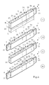
- Fig. 3 representations 15 to 18: Different embodiments of the actuator of an ultrasonic motor according to the invention
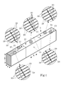
- Fig. 4 An embodiment of the actuator of an ultrasonic motor according to the invention
- Fig. 5 Another embodiment of the actuator of an ultrasonic motor according to the invention
- FIG. 10 Representations 35 and 36: electrically excited regions of the ultrasonic actuator of an ultrasonic motor according to the invention in a circuit according to FIG. 6 and FIG. 7;
- FIG. Figures 37 and 38 electrically excited regions of the ultrasonic actuator of an ultrasonic motor according to the invention in a circuit according to FIG. 8;
- Representations 39 and 40 electrically excited regions of the ultrasonic actuator of an ultrasonic motor according to the invention in a circuit according to FIG. 9
- FIG. 13 Representation of possible trajectories of a point on the friction element of an actuator of an ultrasonic motor according to the invention in a two-phase excitation
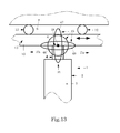
- Fig. 15 Possible embodiment of the ultrasonic motor according to the invention as a drive of a lens in a micro-objective
- the possible embodiment of a linear ultrasonic motor according to the invention shown there comprises a rectangular ultrasound actuator 1, which simultaneously functions as a waveguide resonator 2 for an acoustic standing wave, in the form of a piezoelectric plate 3 with a friction element 4 arranged on its end faces
- Ultrasound actuator in this case has two oppositely arranged and parallel to each other extending end faces, wherein the end faces are formed by the smallest in terms of area side surfaces of the ultrasonic actuator.
- the friction element is in mechanical (frictional) contact with a friction layer 10, which is arranged on a driven element 11 in the form of a rod 13 so as to completely cover the corresponding side surface of the element to be driven.
- the cross-sectional area of the friction element tapers in the direction of the friction layer, starting from the contact surface between the piezoelectric plate and the friction element.
- the driven element is mounted linearly movable over two ball bearings 12.
- the ultrasonic actuator 1 is arranged in the holder 5 of the housing 6 so that it can be displaced along the guide rails 7.
- the friction element 4 is pressed with its friction surface 8 by means of the spring 9 to the friction layer 10 of the element 11 to be driven.
- Fig. 2 shows an embodiment of a rotary ultrasonic motor according to the invention, which differs slightly from the structure of the linear ultrasonic motor of FIG. 1, which is why in the following only the corresponding differences will be discussed.
- the driven element 11 here has the shape of a round disc and represents a rotor 14, on the outer peripheral surface of the friction layer 10 is arranged. A arranged on the rotor and connected to this shaft is rotatably supported by the ball bearing 12.
- each of the ultrasound actuators shown there comprises two largest surfaces 19, which are the largest in area, two long side surfaces 20 and two short side surfaces, which form end faces 21. Furthermore, each of the ultrasonic actuators shown in Figures 15 through 18 has a length L, a width B, and a thickness T.
- Each of the ultrasonic actuators shown in Figures 15 to 18 is divided along its length into three parts of length l, the central part forming a longitudinal acoustic wave generator 22 and the peripheral parts adjacent to the central part forming generators 23 for an acoustic bending sweep ,
- the generators 23 for an acoustic bending propagation along the thickness direction of the piezoelectric plate or the ultrasonic actuator into two equally sized and electrically individually controllable sub-generators 24 and 25 are divided, the sub-generators layers of exciter electrodes, layers of general Have electrodes and interposed layers of piezoceramic, wherein the common electrodes and the excitation electrodes of each sub-generator are connected to the electrical excitation device.
- the respective generator for a longitudinal acoustic wave 22 along the thickness direction of the piezoelectric plate or the ultrasonic actuator is divided into two equal and electrically individually controllable generator parts 26 and 27, wherein each generator part comprises layers of excitation electrodes, layers of common electrodes and layers of piezoceramic disposed therebetween, and the common electrodes and the excitation electrodes of each generator part are connected to the electrical exciter device.
- a friction element 4 is arranged only at one of the two end faces 21 in the ultrasound actuators according to FIGS. 15 and 17, a friction element 4 is provided in the ultrasound actuators according to FIGS. 16 and 18 at both end faces 21. In all cases, the friction element 4 possesses a rectangular shape with a friction surface 8 at its free end.
- the length L of the piezoelectric plate 1 is set to be approximately equal to half the wavelength ⁇ l along the length L in the waveguide resonator 2 with the frequency f a is propagating longitudinal acoustic deformation wave, so that forms the first mode of a longitudinal acoustic wave in the piezoelectric plate 3.
- N is dependent on the type of piezoceramic.
- the thickness T of the piezoelectric plate 3 of the ultrasonic actuator 1 is selected so that in the piezoelectric plate 3 at the length L an acoustic deformation standing wave propagates at the same frequency f a , so that in the piezoelectric plate 3, the third mode of acoustic Forming bending shaft.
- the width B of the piezoelectric plate 3 may be in the range of 2T to 3T.
- Fig. 4 shows a possible internal structure of the piezoelectric plate 3 and the Ultraschallaktors 1 according to the representations 15 and 16 of Fig. 3, while Fig. 5 shows a possible internal structure of the piezoelectric plate 3 and the Ultraschallaktors 1 according to the representations 17 and 18 of FIG. 3 shows.
- the generators 22 and 23 of the piezoelectric plate 3 comprise excitation electrodes 28, common electrodes 29, and layers of piezoceramic 30 disposed therebetween. Both the excitation electrodes and the general electrodes are arranged parallel to the main surfaces of the ultrasound actuator and the piezoelectric plate, respectively. Adjacent piezoceramic layers 30 are oppositely polarized, the polarization direction being perpendicular to the electrodes 28 and 29, respectively. The polarization direction is indicated in FIG. 4 by an arrow with the index p in each case.
- FIG. 6 shows a possibility for the electrical connection of the electrodes of the generators of an ultrasonic actuator of an ultrasonic motor according to the invention according to FIG. 5 when using a two-phase excitation device for symmetrical two-phase excitation of the generators 22 and 23.
- the adjacent piezoceramic layers 30 of the generator parts 24 and 25 have the same direction of polarization. It is possible that the polarization direction of the piezoceramic layers 30 in the partial generators 24-with respect to the piezoceramic layers 30 in the partial generators 25 -is different. Likewise, it is possible that the polarization direction of the piezoceramic layers 30 in the partial generators 26 - with respect to the piezoceramic layers 30 in the partial generators 25 - is different.
- FIG. 6 further shows a block diagram relating to the connection of the electrodes 28 and 29 of the generators 22 and 23 of the piezoelectric plate 3 to a two-phase electrical excitation device 31.
- the electric two-phase excitation device 31 consists here of the generators for the electrical voltages 32 and 33. These generators provide the alternating electrical voltages U1 and U2 with the same frequency f a , which are phase-shifted by the angle ⁇ to each other.
- the voltage U1 is applied via the terminals a, b to the electrodes 28, 29 of the generators 22, while the voltage U2 is applied via the terminals d, c to the electrodes 28, 29 of the generators 23.
- FIG. 7 shows a further possibility for the electrical connection of the electrodes of the generators of an ultrasonic actuator of an ultrasonic motor according to the invention according to FIG. 5 when using a two-phase excitation device for the symmetrical two-phase excitation of the generators 22 and 23.
- Fig. 7 also shows the block diagram relating to the connection of the electrodes 28 and 29 of the generators 22 and 23 to the electric two-phase exciter device 31 of the piezoelectric plate 3.
- the common electrodes 29 are connected to each other here.
- FIG. 8 shows a possibility for electrical connection of the electrodes of the generators of an ultrasonic actuator of an ultrasonic motor according to the invention according to FIG. 5 when using a single-phase excitation device. Furthermore, FIG. 8 shows the block diagram relating to the connection of the electrodes 28 and 29 of the generators 22 and 23 of the ultrasonic actuator to the electrical excitation device 31.
- the electrical excitation device 31 consists of the generator 32, which provides the alternating electrical voltage U1. This voltage is applied via the terminals a and b to the electrodes 28 and 29 of the generator 22 and via the switch 34 and the terminals c to the electrodes 28 and 29 of the part generators 24 of the generators 23, or it will be via the switch 34, the connections d is connected to the electrodes 28 and 29 of the partial generators 25 of the generators 23.
- the electrical circuit shown in FIG. 8 realizes the symmetrical excitation of the generator 22 and the asymmetrical excitation of the generators 23.
- FIG. 9 shows a further possibility for electrical connection of the electrodes of the generators of an ultrasonic actuator of an ultrasonic motor according to the invention according to FIG. 5 when using a single-phase exciter device.
- FIG. 9 also shows a corresponding block diagram relating to the connection of the electrodes 28 and 29 of the generators 22 and 23 of the ultrasound actuator to the electrical exciter device 31.
- the voltage U1 is applied via the switch 34 and the terminals a, d to the electrodes 28 and 29 of the partial generators 24 of the generators 23 and to the electrodes 28 and 29 of the generator 27 of the generator 22. It is also possible to apply the voltage U1 via the switch 34 and the terminals e, c to the electrodes 28 and 29 of the partial generators 25 of the generators 23 and to the electrodes 28 and 29 of the generator 27 of the generator 22.
- the electrical circuit shown in FIG. 9 enables the asymmetrical excitation of the generator 22 and the asymmetrical excitation of the generators 23.
- the representations 35 and 36 of FIG. 10 illustrate the electrically excited regions of the ultrasound actuator or of the generators or of the subgenerators of an ultrasound motor according to the invention when an electrical circuit according to FIG. 6 and FIG. 7 is used. while in the generators 23, the voltage U2 is applied. Since the partial generators 24 and 25 or the corresponding piezoelectric material have or have different directions of polarization, the hatching is different there, although the same electrical potential is present in the different generator parts.
- Representations 37 and 38 show the electrically excited regions of the ultrasonic actuator or of the generators or of the partial generators of an ultrasonic motor according to the invention in a circuit according to FIG. 8. Here lies both on the generator 22 and on the corresponding partial generators 24 and 25 of the generators 23 Voltage U1 on.
- illustrations 39 and 40 show the electrically excited regions of the ultrasound actuator or of the generators or of the subgenerators of an ultrasound motor according to the invention in a circuit according to FIG. 9.
- Plots 41 and 42 of Fig. 11 show the phases of maximum deformation of the longitudinal standing wave generated in the actuator of an ultrasonic motor according to the invention, while representations 43 and 44 show the phases of maximum deformation of the bending shaft generated in the actuator of an ultrasonic motor according to the present invention.
- the two standing waves described above are simultaneously generated in the piezoelectric plate 3, ie a longitudinal standing wave and a bending wave wave.
- the friction element 4 moves according to FIG. 11 on a closed path of movement 45, which may have the shape of a circle 46 or the shape of an ellipse 47 or 48 for the point 49 lying on the friction surface 8 of the friction element 4.
- the shape of the trajectory 45 and its inclination to the friction layer 10 of the driven element 11 is determined by the ratio of the amplitude of the voltages U1 and U2 and the value of the phase shift angle between these voltages.
- the shape of the movement path of the friction element 4 and the point 49 on its friction surface is determined by the value k in the abovementioned limits.
- the movement path shown in Fig. 14 may have the shape of an inclined line 50 or the shape of a narrow ellipse 51.
- the longitudinal force F l forms , which presses and presses the friction surface 8 of the friction element 4 against the friction layer 10 of the element 11 to be driven. This force determines the frictional force between the friction element 4 and the friction layer 10 of the element 11 to be driven.
- the transverse bending force F n which causes the driven element 11 to move, is produced by the acoustic bending shaft. This force is created by bending the piezoelectric plate 3 of the ultrasonic actuator 1 through its thickness T.
- the thickness T of the piezoelectric plate in the motor according to the invention is significantly smaller than the height of the piezoelectric plate in previously known ultrasonic motors. This is due to the number of generated in the piezoelectric plate 3 acoustic half waves - due to the formation of the first mode of the longitudinal standing wave and the third mode of Biegestehwelle - conditioned.
- the ultrasonic motor according to the invention works much more effectively than, for example, the ultrasonic motors known from the patents US Pat. Nos. 5,877,579, 5,714,833 and 6,806,620 B1.
- the ultrasonic motor according to the invention requires less electrical energy, whereby smaller mechanical losses occur at higher speeds of movement of the element to be driven. At the same time, the motor enables higher movement forces.
- FIG. 15 shows a possible embodiment of the ultrasonic motor according to the invention as drive of a lens 53 in a microlens 52 for focusing the image of an optical transmitter 54.
Landscapes
- General Electrical Machinery Utilizing Piezoelectricity, Electrostriction Or Magnetostriction (AREA)
Abstract
La présente invention concerne un moteur ultrasonique comprenant un actionneur ultrasonique fonctionnant en tant que résonateur guide d'onde optique et se présentant sous la forme d'une plaque piézoélectrique rectangulaire qui présente deux surfaces principales de surface importante et des surfaces latérales qui relient les surfaces principales entre elles ; un élément à entraîner ; et un dispositif d'excitation électrique. Contre au moins une surface latérale de l'actionneur ultrasonique est disposé au moins un élément de friction qui est en contact de friction avec l'élément à entraîner et subdivise la plaque piézoélectrique le long de sa direction longitudinale en trois parties, la partie centrale formant un générateur pour une onde acoustique stationnaire longitudinale et les parties périphériques adjacentes à la partie centrale formant des générateurs pour une onde acoustique stationnaire de flexion, et chacun des générateurs étant relié au dispositif d'excitation électrique et pouvant être commandé électriquement, chacun des générateurs d'onde acoustique stationnaire de flexion étant subdivisé sur la largeur de la plaque piézoélectrique en deux sous-générateurs de même taille qui peuvent être commandés électriquement séparément, et les sous-générateurs présentant respectivement des couches d'électrodes d'excitation et des couches d'électrodes générales, et, intercalées entre elles, des couches de piézocéramique.
Priority Applications (2)
| Application Number | Priority Date | Filing Date | Title |
|---|---|---|---|
| US15/327,846 US10432112B2 (en) | 2014-07-23 | 2015-07-21 | Ultrasonic motor |
| EP15757120.9A EP3172826B1 (fr) | 2014-07-23 | 2015-07-21 | Moteur ultrasonique |
Applications Claiming Priority (2)
| Application Number | Priority Date | Filing Date | Title |
|---|---|---|---|
| DE102014214357 | 2014-07-23 | ||
| DE102014214357.8 | 2014-07-23 |
Publications (1)
| Publication Number | Publication Date |
|---|---|
| WO2016012020A1 true WO2016012020A1 (fr) | 2016-01-28 |
Family
ID=54035062
Family Applications (1)
| Application Number | Title | Priority Date | Filing Date |
|---|---|---|---|
| PCT/DE2015/200409 Ceased WO2016012020A1 (fr) | 2014-07-23 | 2015-07-21 | Moteur ultrasonique |
Country Status (3)
| Country | Link |
|---|---|
| US (1) | US10432112B2 (fr) |
| EP (1) | EP3172826B1 (fr) |
| WO (1) | WO2016012020A1 (fr) |
Cited By (2)
| Publication number | Priority date | Publication date | Assignee | Title |
|---|---|---|---|---|
| US20160351786A1 (en) * | 2014-02-18 | 2016-12-01 | Sharp Kabushiki Kaisha | Friction drive actuator |
| US20170358733A1 (en) * | 2016-06-08 | 2017-12-14 | Tdk Corporation | Piezoelectric device |
Families Citing this family (5)
| Publication number | Priority date | Publication date | Assignee | Title |
|---|---|---|---|---|
| US11214789B2 (en) | 2016-05-03 | 2022-01-04 | Flodesign Sonics, Inc. | Concentration and washing of particles with acoustics |
| DE102017107275A1 (de) * | 2017-04-05 | 2018-10-11 | Physik Instrumente (Pi) Gmbh & Co. Kg | Ultraschallmotor |
| EP3725092A4 (fr) | 2017-12-14 | 2021-09-22 | FloDesign Sonics, Inc. | Circuit d'excitation et circuit de commande de transducteur acoustique |
| DE102018104928B3 (de) * | 2018-03-05 | 2019-05-29 | Physik Instrumente (Pi) Gmbh & Co. Kg | Ultraschallmotor |
| TWI678879B (zh) | 2018-11-27 | 2019-12-01 | 財團法人工業技術研究院 | 超音波線性致動裝置 |
Citations (5)
| Publication number | Priority date | Publication date | Assignee | Title |
|---|---|---|---|---|
| US5714833A (en) | 1993-08-03 | 1998-02-03 | Nanomotion Ltd. | Ceramic motor |
| US5877579A (en) | 1993-07-09 | 1999-03-02 | Nanomotion Ltd. | Ceramic motor |
| DE19938954A1 (de) * | 1999-08-17 | 2001-03-08 | Pi Ceramic Gmbh Keramische Tec | Piezoelektrischer Antrieb, insbesondere zur Erzeugung von Rotations- oder Translationsbewegungen, die stetig oder schrittweise erfolgen können |
| US20060238072A1 (en) * | 2005-04-26 | 2006-10-26 | Olympus Corporation | Ultrasonic motor |
| US20080122316A1 (en) * | 2006-11-29 | 2008-05-29 | Olympus Corporation | Ultrasonic motor and microscope stage |
Family Cites Families (6)
| Publication number | Priority date | Publication date | Assignee | Title |
|---|---|---|---|---|
| JPH01234067A (ja) * | 1988-03-11 | 1989-09-19 | Nec Corp | 超音波モータ |
| US5136200A (en) * | 1989-07-27 | 1992-08-04 | Olympus Optical Co., Ltd. | Ultransonic motor |
| DE69941195D1 (de) * | 1999-05-31 | 2009-09-10 | Nanomotion Ltd | Beschleunigungs- und Bremsmethode mit einem piezoelektrischen Motor |
| US7471030B2 (en) * | 2006-03-08 | 2008-12-30 | Dynamic Structures And Materials, Llc | Spring biasing locking mechanism for step and repeat motors |
| DE102008012992A1 (de) * | 2008-03-07 | 2009-09-10 | Physik Instrumente (Pi) Gmbh & Co. Kg | Ultraschallmotor |
| JP5429141B2 (ja) * | 2010-01-19 | 2014-02-26 | Tdk株式会社 | 圧電アクチュエータ及び圧電アクチュエータの製造方法 |
-
2015
- 2015-07-21 US US15/327,846 patent/US10432112B2/en active Active
- 2015-07-21 WO PCT/DE2015/200409 patent/WO2016012020A1/fr not_active Ceased
- 2015-07-21 EP EP15757120.9A patent/EP3172826B1/fr active Active
Patent Citations (6)
| Publication number | Priority date | Publication date | Assignee | Title |
|---|---|---|---|---|
| US5877579A (en) | 1993-07-09 | 1999-03-02 | Nanomotion Ltd. | Ceramic motor |
| US5714833A (en) | 1993-08-03 | 1998-02-03 | Nanomotion Ltd. | Ceramic motor |
| DE19938954A1 (de) * | 1999-08-17 | 2001-03-08 | Pi Ceramic Gmbh Keramische Tec | Piezoelektrischer Antrieb, insbesondere zur Erzeugung von Rotations- oder Translationsbewegungen, die stetig oder schrittweise erfolgen können |
| US6806620B1 (en) | 1999-08-17 | 2004-10-19 | Pi Ceramic Gmbh Keramische Technologien Und Bauelemente | Piezoelectric drive excited by longitudinal and flexural waves |
| US20060238072A1 (en) * | 2005-04-26 | 2006-10-26 | Olympus Corporation | Ultrasonic motor |
| US20080122316A1 (en) * | 2006-11-29 | 2008-05-29 | Olympus Corporation | Ultrasonic motor and microscope stage |
Cited By (6)
| Publication number | Priority date | Publication date | Assignee | Title |
|---|---|---|---|---|
| US20160351786A1 (en) * | 2014-02-18 | 2016-12-01 | Sharp Kabushiki Kaisha | Friction drive actuator |
| US10211390B2 (en) * | 2014-02-18 | 2019-02-19 | Sharp Kabushiki Kaisha | Friction drive actuator |
| US20170358733A1 (en) * | 2016-06-08 | 2017-12-14 | Tdk Corporation | Piezoelectric device |
| CN107482111A (zh) * | 2016-06-08 | 2017-12-15 | Tdk株式会社 | 压电元件 |
| CN107482111B (zh) * | 2016-06-08 | 2020-01-07 | Tdk株式会社 | 压电元件 |
| US10686119B2 (en) * | 2016-06-08 | 2020-06-16 | Tdk Corporation | Piezoelectric device |
Also Published As
| Publication number | Publication date |
|---|---|
| EP3172826A1 (fr) | 2017-05-31 |
| EP3172826B1 (fr) | 2019-04-17 |
| US10432112B2 (en) | 2019-10-01 |
| US20170214339A1 (en) | 2017-07-27 |
Similar Documents
| Publication | Publication Date | Title |
|---|---|---|
| EP3172826B1 (fr) | Moteur ultrasonique | |
| DE102014205577B4 (de) | Ultraschallmotor | |
| DE69412247T2 (de) | Piezoelektrischer Transformator | |
| EP3084852B1 (fr) | Moteur à ultrasons | |
| WO2005114760A1 (fr) | Moteur a ultrasons piezo-electrique | |
| WO1996026551A1 (fr) | Element d'entrainement a ultrasons | |
| DE102009051395A1 (de) | Aktuator | |
| DE102013224569B3 (de) | Ultraschallmotor und Verfahren zum Betreiben eines solchen Ultraschallmotors | |
| DE3833342A1 (de) | Piezomotor | |
| WO2015176711A1 (fr) | Actionneur à ultrasons | |
| DE102013110356B4 (de) | Ultraschallaktor | |
| DE4408618B4 (de) | Verstellantrieb aus Bimorphelementen | |
| DE102008058484A1 (de) | Hochpräziser Ultraschallmotor | |
| DE102018104928B3 (de) | Ultraschallmotor | |
| EP2824824A1 (fr) | Dispositif d'entraînement | |
| WO2017206992A1 (fr) | Moteur à ultrasons à plaque d'actionnement excitable diagonalement | |
| DE102015120282A1 (de) | Ultraschallmotor | |
| DE102011087542B3 (de) | Zweiphasen-Ultraschallmotor | |
| DE1488698C3 (de) | Elektrische Antriebsvorrichtung, insbesondere Antriebsvorrichtung fur eine kleine mechanische Nutzlast | |
| DE102006020553A1 (de) | Piezoelektrischer Vibrator und Ultraschallmotor mit piezoelektrischem Vibrator | |
| EP3526823B1 (fr) | Moteur à ultrasons | |
| DE102013101020B4 (de) | Ultraschallaktor und Ultraschallmotor mit einem solchen Ultraschallaktor | |
| DE102013203836B4 (de) | Piezoelektrisches Ultraschall-Vibrationselement und seine Verwendung | |
| EP3607592B1 (fr) | Procédé de fonctionnement d'un moteur à ultrasons | |
| DE102013221414B4 (de) | Ultraschallmotor |
Legal Events
| Date | Code | Title | Description |
|---|---|---|---|
| 121 | Ep: the epo has been informed by wipo that ep was designated in this application |
Ref document number: 15757120 Country of ref document: EP Kind code of ref document: A1 |
|
| REEP | Request for entry into the european phase |
Ref document number: 2015757120 Country of ref document: EP |
|
| WWE | Wipo information: entry into national phase |
Ref document number: 2015757120 Country of ref document: EP |
|
| WWE | Wipo information: entry into national phase |
Ref document number: 15327846 Country of ref document: US |