WO2016013108A1 - 回転電機 - Google Patents
回転電機 Download PDFInfo
- Publication number
- WO2016013108A1 WO2016013108A1 PCT/JP2014/069684 JP2014069684W WO2016013108A1 WO 2016013108 A1 WO2016013108 A1 WO 2016013108A1 JP 2014069684 W JP2014069684 W JP 2014069684W WO 2016013108 A1 WO2016013108 A1 WO 2016013108A1
- Authority
- WO
- WIPO (PCT)
- Prior art keywords
- rotor
- winding
- winding support
- spacing piece
- support portion
- Prior art date
- Legal status (The legal status is an assumption and is not a legal conclusion. Google has not performed a legal analysis and makes no representation as to the accuracy of the status listed.)
- Ceased
Links
Images


Classifications
-
- H—ELECTRICITY
- H02—GENERATION; CONVERSION OR DISTRIBUTION OF ELECTRIC POWER
- H02K—DYNAMO-ELECTRIC MACHINES
- H02K3/00—Details of windings
- H02K3/04—Windings characterised by the conductor shape, form or construction, e.g. with bar conductors
- H02K3/24—Windings characterised by the conductor shape, form or construction, e.g. with bar conductors with channels or ducts for cooling medium between the conductors
-
- H—ELECTRICITY
- H02—GENERATION; CONVERSION OR DISTRIBUTION OF ELECTRIC POWER
- H02K—DYNAMO-ELECTRIC MACHINES
- H02K1/00—Details of the magnetic circuit
- H02K1/06—Details of the magnetic circuit characterised by the shape, form or construction
- H02K1/22—Rotating parts of the magnetic circuit
- H02K1/32—Rotating parts of the magnetic circuit with channels or ducts for flow of cooling medium
-
- H—ELECTRICITY
- H02—GENERATION; CONVERSION OR DISTRIBUTION OF ELECTRIC POWER
- H02K—DYNAMO-ELECTRIC MACHINES
- H02K7/00—Arrangements for handling mechanical energy structurally associated with dynamo-electric machines, e.g. structural association with mechanical driving motors or auxiliary dynamo-electric machines
- H02K7/18—Structural association of electric generators with mechanical driving motors, e.g. with turbines
- H02K7/1807—Rotary generators
- H02K7/1823—Rotary generators structurally associated with turbines or similar engines
-
- H—ELECTRICITY
- H02—GENERATION; CONVERSION OR DISTRIBUTION OF ELECTRIC POWER
- H02K—DYNAMO-ELECTRIC MACHINES
- H02K9/00—Arrangements for cooling or ventilating
- H02K9/08—Arrangements for cooling or ventilating by gaseous cooling medium circulating wholly within the machine casing
Definitions
- the present invention relates to a rotating electrical machine used for a turbine generator or the like, and more particularly to a rotating electrical machine with improved rotor cooling performance.
- the rotor winding end of the conventional rotating electrical machine is provided with a second flow path that penetrates the high-speed flow region and the vortex flow region in the mountain-shaped portion of the insulator constituting the cooling air passage,
- the eddy current region is eliminated to make the temperature distribution uniform (for example, refer to Patent Document 1).
- the rotor winding end is cooled by a cooling gas flowing between adjacent coils held by a spacing piece that is an insulator.
- a cooling gas flowing between adjacent coils held by a spacing piece that is an insulator In the case of increasing the rotor current, there is a problem that the rotor temperature rises above the heat resistance temperature of the insulator as the rotor field current increases.
- the present invention was made to solve the above-mentioned problems, improving the cooling performance of the rotor winding end of the rotor of the rotating electrical machine, and increasing the output of the rotating electrical machine, An object of the present invention is to obtain a rotating electrical machine having a rotor that does not cause poor insulation.
- a rotating electrical machine includes a rotor winding wound around a rotor core at an interval, and a rotor winding in which the rotor winding is formed so as to protrude from an axial end surface of the rotor core.
- An end piece, a spacing piece disposed between adjacent rotor winding ends, a chevron-shaped winding support portion provided on both side surfaces of the spacing piece and having an obtuse angle, and both side surfaces of the spacing piece A meandering air passage formed by a mountain-shaped winding support portion, and a wavy winding support portion formed along the meandering air passage in the meandering air passage. .
- the rotating electrical machine includes a rotor winding wound around the rotor core at an interval, and a rotor formed by projecting the rotor winding on an end surface in the axial direction of the rotor core.
- Winding ends, spacing pieces disposed between adjacent rotor winding ends, arcuate winding supports provided on both sides of the spacing pieces, and arcuate shapes on both sides of the spacing pieces A meandering air passage formed by the winding support portion, and a wavy winding support portion formed along the meandering air passage in the meandering air passage and having a shape connecting the arcuate winding support portions. It is characterized by that.
- the flow separation at the apex of the mountain-shaped winding support is suppressed, the vortex region behind the mountain-shaped winding support is reduced, and the cooling gas is uniform throughout the meandering air passage. Therefore, the pressure loss can be remarkably reduced. Furthermore, it is possible to suppress a local temperature rise at the rotor winding end by making the flow in the meandering air passage formed in the spacing piece uniform.
- FIG. 2 is an enlarged cross-sectional view of a main part around a rotor winding end in FIG. 1. It is a perspective view which shows the state which removed the coil holding ring and end ring of the rotor in FIG. It is a top view which shows the principal part of the rotor coil
- FIG. 1 is a cross-sectional side view of a turbine generator using a rotating electrical machine according to Embodiment 1 of the present invention.
- 2 is an enlarged cross-sectional view of a main part around the rotor winding end in FIG. 1, and is a side view of a region surrounded by a dotted line in FIG. 3 is a perspective view of the rotor showing a state in which the coil holding ring and the end ring in FIG. 1 are removed
- FIG. 4 is a plan view showing the main part of the rotor winding end in FIG. It is.
- the rotating electrical machine 100 includes a hollow cylindrical stator 1 and a cylindrical rotor 5 having a diameter slightly smaller than the diameter of the hollow portion through a gap (air gap) 25. Are arranged concentrically.
- the stator 1 and the rotor 5 are each provided with a conductive coil such as copper in the axial direction of the iron core slot.
- the stator 1 and the rotor 5 are fixed. Current is induced on the child 1 side.
- the stator 1 and the rotor 5 generate a large amount of heat due to electrical loss or the like, and thus require special cooling.
- the rotating electrical machine 100 performs forced cooling by installing a fan 26 in the rotor 5 and sending a cooling gas into the rotating electrical machine 100.
- a gas such as air or hydrogen is used as the cooling gas for cooling the inside of the rotating electrical machine 100.
- the turbine generator 200 includes a stator 1, a rotor 5, a fan 26, and a cooler 27.
- the stator 1 includes a stator core 2, a stator winding 3, and a duct 4.
- the rotor 5 includes a rotor core 6, a rotor winding 7, a coil holding ring 30, an end ring 31, and a rotating shaft 13.
- the rotating shaft 13 is rotatably supported by a bearing (not shown), and the fan 26 is attached to the end of the rotating shaft 13 symmetrically.
- the outer periphery of the rotor core 6 and the inner periphery of the stator core 2 are separated by a gap (air gap) 25.
- the rotating shaft 13 rotates and the cooling gas pumped by the fan 26 is divided into two hands, and one cooling gas is introduced from the opening 31a (see FIG. 2) of the end ring 31 to be a rotor in the coil holding ring 30.
- the winding end 8 is cooled and discharged from the notch exhaust passage 15 of the rotor magnetic pole 14 (see FIG. 3) into the gap 25 in the direction of the arrow A3.
- the other cooling gas cools the end of the stator winding 3 to flow in the gap 25 in the axial direction, and merges with the cooling gas indicated by the arrow A3.
- the rotor winding 7 is centered on the rotor magnetic poles 14 in slots (not shown) provided in a plurality of left and right rotor iron cores 6 of the rotor magnetic poles 14.
- a plurality of bowl-shaped rectangular rotor coils 11 formed by concentrated winding are arranged concentrically, and are composed of a plurality of field coils connected in series.
- the rotor coil 11 has a coil side (not shown) in the slot and a rotor winding end 8 protruding from the end face of the rotor core 6.
- the rotor winding end portion 8 has a pair of linear portions 9 projecting from the end face of the rotor core 6 in the direction of the rotational axis and a connecting portion 10 that connects both the linear portions 9.
- a plurality of rotor winding end portions 8 are disposed so as to protrude from the end portions of the rotor magnetic poles 14 at intervals.
- the coil holding ring 30 covers and holds the outer circumferences of the spacing pieces 18 disposed between the rotor winding end 8 and the adjacent rotor winding end 8. Is fitted into the end of the rotor core 6.
- An end ring 31 is fitted to the other end portion of the coil holding ring 30, and the rotor winding end portion 8 is moved from the space between the opening portion 31 a provided penetrating in the direction of the rotation axis and the rotation shaft 13.
- a cooling gas to be cooled is introduced as indicated by an arrow A1.
- the cooling gas that has cooled the rotor winding end 8 is collected at a lower portion of the circumferential width center portion of the rotor winding end 8 through a meandering air passage (not shown) provided in the spacing piece 18.
- a partition plate 20 leading to the cutout exhaust passage 15 is provided on the rotating shaft 13 as indicated by an arrow A2 (see FIG. 2).
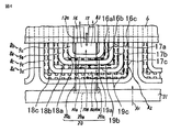
- the rotor winding end portions 8 a, 8 b, 8 c, and 8 d are respectively a pair of linear portions 9 a, 9 a, 9 b, 9 c, and 9 d, and connection portions 10. 10a, 10b, 10c, 10d. Between the straight portions 9a, 9b, 9c, and 9d, 16a, 16b, and 16c, which are spacing pieces 16, are disposed, respectively. Moreover, 18a, 18b, 18c which is the space
- each spacing piece 16a, 16b, 16c On both side surfaces of each spacing piece 16a, 16b, 16c are 17a, 17b which are meandering air passages 17 that meander along the longitudinal direction of the side wall surfaces of the abutting linear portions 9a, 9b, 9c, 9d. , 17c. Further, on both side surface portions of each spacing piece 18a, 18b, 18c, 19a, which is a meandering air passage 19 extending meandering along the longitudinal direction of the side wall surface of each of the connecting portions 10a, 10b, 10c, 10d that abuts. 19b and 19c are configured.
- the side wall surfaces of the straight portions 9a, 9b, 9c, and 9d constitute one wall surface of the meandering air passages 17a, 17b, and 17c, respectively.
- the side wall surfaces of the connecting portions 10a, 10b, 10c, 10d constitute one wall surface of 19a, 19b, 19c.
- the partition plate 20 has a pair of side plates 20a whose lower part is inserted into a groove (not shown) of the rotary shaft 13 (see FIG. 2) and whose one side end surface is in contact with the side wall of the rotor magnetic pole 14. It is comprised by the end plate 20b joined to the other side end surface of a pair of side plate 20a, and arrange
- each spacing piece 16 On both side surfaces of each spacing piece 16a, 18a, meandering grooves 21 (not shown) that meander and extend in the longitudinal direction of each spacing piece 16a, 18a are formed.
- the interval piece 16a is arranged between the straight portions 9a and 9b, and the interval piece 18a is arranged between the connecting portions 10a and 10b.
- a meandering air passage 17a is formed by meandering grooves 21 (not shown) of the spacing pieces 16a and the side wall surfaces of the straight portions 9a, 9b.
- the meandering air passage 19a is formed by the meandering groove 21 of the spacing piece 18a and the side wall surfaces of the connecting portions 10a and 10b.
- the introduced cooling gas cools the straight portions 9a and 9b and the connecting portions 10a and 10b while continuously flowing through the meandering air passages 17a and 19a as indicated by an arrow A2, and the left and right side plates of the partition plate 20 are cooled. Derived into the space surrounded by 20a.
- the cooling gas at the rotor winding end 8 is introduced from the opening 31a (see FIG. 2) of the end ring 31 as indicated by an arrow A1, and then the spacing pieces 16a, 16b, and 16c.
- the meandering air on each side of the spacing pieces 18a, 18b, 18c is introduced into the meandering air passages 17a, 17b, 17c on both sides and from the meandering air passages 17a, 17b, 17c in the direction of the arrow A2 represented by a dashed line. It flows continuously into the paths 19a, 19b, 19c.
- the electrical resistance loss in the rotor winding end 8a, 8b, 8c, and 8d is absorbed by the cooling gas flowing through the meandering air passages 17a, 17b, 17c, 19a, 19b, and 19c.
- the temperature rise of the child winding end 8 is suppressed.
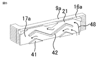
- FIG. 5 is a perspective view showing a spacing piece of the rotating electric machine according to Embodiment 1 of the present invention.
- FIG. 5 shows a state where the coil holding ring 30 is removed.
- the spacing piece 16a includes a mountain-shaped winding support portion 41 and a wavy winding support portion 42 in the meandering air passage 17a.
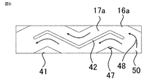
- FIG. 6 is a side view showing the spacing piece of the rotating electrical machine according to the first embodiment of the present invention.
- the apex angle 47 of the mountain-shaped winding support part 41 is an obtuse angle. As shown in FIGS.
- the cooling gas 48 that has flowed into the meandering air passage 17 a provided in the spacing piece 16 a is split into two at the end of the wave-like winding support portion 42.
- the apex angle 47 of the mountain-shaped winding support portion 41 is an obtuse angle, the separation of the flow at the apex of the mountain-shaped winding support portion 41 is suppressed, and the mountain-shaped winding support
- the cooling gas flows uniformly over the entire meandering flow path without generating a vortex region generated behind the support portion 41.
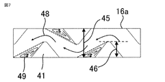
- FIG. 7 is a side view showing the state of the spacing piece of the rotating electrical machine in the comparative example.
- the rotor windings 7 having a thickness of several millimeters are usually stacked in the vertical direction in the figure, so that the spacing pieces 16a maintain the holding force of the rotor windings 7 over the entire area.
- the apex angle of the mountain-shaped winding support portion 41 is an acute angle, and the flow of the cooling gas 48 flowing through the meandering air passage 17a is separated at the apex of the mountain-shaped winding support portion 41, and the mountain-shaped winding support portion 41 A swirling vortex region 49 is formed behind the line support portion 41. Due to the presence of the swirl region 49, the cross-sectional area of the flow path through which the cooling gas 48 actually flows is reduced, and a high-speed flow region with an increased flow velocity is generated. As a result, the pressure loss in the ventilation path increases. In addition, the vortex region 49 becomes a heat insulating layer in which heat exchange between the rotor winding end 8 and the cooling gas 48 is suppressed. For this reason, the rotor winding end portion 8 in contact with the vortex region 49 has a higher temperature than the rotor winding end portion 8 in contact with the high-speed flow region.
- FIG. 8 is a perspective view showing the main part of the spacing piece of the rotating electrical machine in the comparative example.
- the both sides of each spacing piece 16a, 18a have the same groove depth Di and width W, and the longitudinal direction of each spacing piece 16a, 18a.
- a meandering groove 21 is formed which meanders and extends toward the end.
- the interval piece 16a is arranged between the straight portions 9a and 9b, and the interval piece 18a is arranged between the connecting portions 10a and 10b.
- a meandering air passage 17a is formed by the meandering groove 21 of the spacing piece 16a and the side wall surfaces of the straight portions 9a, 9b.
- the meandering air passage 19a is formed by the meandering groove 21 of the spacing piece 18a and the side wall surfaces of the connecting portions 10a and 10b.
- the introduced cooling gas cools the straight portions 9a and 9b and the connecting portions 10a and 10b while continuously flowing through the meandering air passages 17a and 19a as indicated by an arrow A2, and the left and right side plates of the partition plate 20 are cooled. Derived into the space surrounded by 20a.
- the flow passage cross-sectional area through which the refrigerant flows substantially increases as compared with the structure of the comparative example, so that the flow velocity decreases, and consequently the pressure loss proportional to the square of the flow velocity is remarkably reduced. be able to. Furthermore, it is possible to suppress a local temperature rise at the rotor winding end 8 by making the flow in the meandering air passage 17a constituted by the spacing pieces 16a uniform.
- the shape of the mountain-shaped winding support 41 is not limited to a triangle, and may be a trapezoid (not shown). Alternatively, as shown in FIG. 9, the shape of the mountain-shaped winding support portion 41 of the spacing piece 16 a may be an arc shape.
- the wavy winding support portion 42 has a shape in which circular arcs are connected, and each meandering air passage 17a partitioned by the wavy winding support portion 42 has a cross-sectional area with respect to the flow direction as constant as possible. .
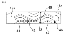
- FIG. FIG. 10 is a side view showing a spacing piece of a rotating electrical machine according to Embodiment 2 of the present invention.
- the spacing piece 16a includes a mountain-shaped winding support portion 41 and a wavy winding support portion 42 in the meandering air passage 17a.
- the peak height 46 of the peak-shaped winding support part 41 is not less than 1/3 and 1/2 or less of the width 45 of the spacing piece, and the apex angle 47 is an obtuse angle. Therefore, the apex of the mountain-shaped winding support portion 41 and the valley portion of the wave-shaped winding support portion 42 have a region 43 that overlaps in the circumferential direction.
- the shape of the mountain-shaped winding support part 41 is not limited to a triangle but may be a trapezoid. Alternatively, the mountain-shaped winding support part 41 may have an arc shape.
- FIG. 11 is a side view showing a spacing piece of a rotating electrical machine according to Embodiment 3 of the present invention.
- the spacing piece 16a includes a mountain-shaped winding support portion 41 and a wave-like winding support portion 42 provided in the meandering air passage 17a.
- the wavy winding support 42 has an end 44 that extends to the vicinity of the center of the cooling gas inlet 50. Therefore, in the third embodiment, in addition to the effects of the first or second embodiment, the left and right sides of the wavy winding support 42 are determined depending on the length by which the end 44 of the wavy winding support 42 protrudes. Can be adjusted so that the flow rate flowing through Therefore, it is possible to further suppress the local temperature distribution at the rotor winding end 8.
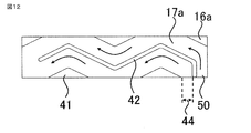
- FIG. 12 is a side view showing a modification of the spacing piece of the rotating electrical machine according to the third embodiment of the present invention.
- interval piece 16a is provided with the mountain-shaped winding support part 41 and the wavy winding support part 42 provided in the meandering ventilation path 17a.
- the end 44 of the wavy winding support 42 may have a structure extending toward the cooling gas inlet 50. Therefore, also in the modified example in the third embodiment, in addition to the effect of the first or second embodiment, the wavy winding support portion is determined by the length of the end 44 of the wavy winding support portion 42 protruding. The flow rate flowing through the left and right of 42 can be adjusted to be equal. Therefore, it is possible to further suppress the local temperature distribution at the rotor winding end 8.
- the number of the wavy winding support portions 42 in the meandering air passage 17a has been described as one, but two or more wavy winding support portions 42 may be arranged in parallel. Good.
- the spacing piece 16a provided in the linear portion 9 has been described.
- the present invention is also applied to the arc-shaped spacing piece 18a provided in the connecting portion 10.
- the first to third embodiments can be similarly applied.
- the present invention has been described on behalf of a rotating electrical machine having a ventilation path, the present invention can also be applied to a spacing piece in a rotating electrical machine having another ventilation path. It should be noted that within the scope of the present invention, the embodiments can be freely combined, or the embodiments can be appropriately modified or omitted.
Landscapes
- Engineering & Computer Science (AREA)
- Power Engineering (AREA)
- Motor Or Generator Cooling System (AREA)
- Windings For Motors And Generators (AREA)
Priority Applications (5)
| Application Number | Priority Date | Filing Date | Title |
|---|---|---|---|
| JP2016535607A JP6165340B2 (ja) | 2014-07-25 | 2014-07-25 | 回転電機 |
| PCT/JP2014/069684 WO2016013108A1 (ja) | 2014-07-25 | 2014-07-25 | 回転電機 |
| US15/303,923 US10418872B2 (en) | 2014-07-25 | 2014-07-25 | Rotary electric machine |
| EP14897952.9A EP3174180B1 (de) | 2014-07-25 | 2014-07-25 | Elektrische rotationsmaschine |
| CN201480080595.4A CN106537733A (zh) | 2014-07-25 | 2014-07-25 | 旋转电机 |
Applications Claiming Priority (1)
| Application Number | Priority Date | Filing Date | Title |
|---|---|---|---|
| PCT/JP2014/069684 WO2016013108A1 (ja) | 2014-07-25 | 2014-07-25 | 回転電機 |
Publications (1)
| Publication Number | Publication Date |
|---|---|
| WO2016013108A1 true WO2016013108A1 (ja) | 2016-01-28 |
Family
ID=55162660
Family Applications (1)
| Application Number | Title | Priority Date | Filing Date |
|---|---|---|---|
| PCT/JP2014/069684 Ceased WO2016013108A1 (ja) | 2014-07-25 | 2014-07-25 | 回転電機 |
Country Status (5)
| Country | Link |
|---|---|
| US (1) | US10418872B2 (de) |
| EP (1) | EP3174180B1 (de) |
| JP (1) | JP6165340B2 (de) |
| CN (1) | CN106537733A (de) |
| WO (1) | WO2016013108A1 (de) |
Families Citing this family (10)
| Publication number | Priority date | Publication date | Assignee | Title |
|---|---|---|---|---|
| CN106537733A (zh) * | 2014-07-25 | 2017-03-22 | 三菱电机株式会社 | 旋转电机 |
| DE102017207659B4 (de) * | 2017-05-08 | 2019-11-14 | Audi Ag | Elektrische Maschine sowie Verfahren zum Herstellen einer elektrischen Maschine |
| CN107947463B (zh) * | 2018-01-10 | 2024-01-19 | 东方电气集团东方电机有限公司 | 汽轮发电机转子端部线圈轴向外冷风路结构 |
| CN107896023B (zh) * | 2018-01-10 | 2023-09-05 | 东方电气集团东方电机有限公司 | 汽轮发电机转子端部线圈两路外冷通风结构 |
| EP3829035B1 (de) * | 2018-07-26 | 2022-04-06 | Mitsubishi Electric Corporation | Rotor für elektrische drehmaschine |
| DE102018216586A1 (de) * | 2018-09-27 | 2020-04-02 | Siemens Aktiengesellschaft | Verblockungselement für Rotorwickelköpfe bei Turbogeneratoren mit Läuferkappe mit radialen Ventilationsbohrungen |
| CN110932445B (zh) * | 2019-12-23 | 2025-04-15 | 中国科学院电工研究所 | 一种定子散热结构及电机 |
| CN111600404A (zh) * | 2020-06-15 | 2020-08-28 | 哈尔滨理工大学 | 具有逐步增压式定子槽钢的矿用防爆电机 |
| GB202106809D0 (en) * | 2021-05-13 | 2021-06-30 | Cummins Generator Technologies | Spacer for rotor windings |
| CN120880004A (zh) * | 2024-04-29 | 2025-10-31 | 罗伯特·博世有限公司 | 电机 |
Citations (3)
| Publication number | Priority date | Publication date | Assignee | Title |
|---|---|---|---|---|
| JPS52151304U (de) * | 1976-05-13 | 1977-11-16 | ||
| JP2004312886A (ja) * | 2003-04-08 | 2004-11-04 | Suzuki Motor Corp | 電動機の冷却構造 |
| JP2013198237A (ja) * | 2012-03-19 | 2013-09-30 | Mitsubishi Electric Corp | 回転電機 |
Family Cites Families (25)
| Publication number | Priority date | Publication date | Assignee | Title |
|---|---|---|---|---|
| US2653255A (en) * | 1952-07-26 | 1953-09-22 | Westinghouse Electric Corp | Separate end-turn rotorventilation |
| US2833944A (en) * | 1957-07-22 | 1958-05-06 | Gen Electric | Ventilation of end turn portions of generator rotor winding |
| JPS5625348A (en) * | 1979-08-08 | 1981-03-11 | Hitachi Ltd | Rotor for rotary electric machine cooled by gas |
| JPS6134849Y2 (de) * | 1980-07-15 | 1986-10-09 | ||
| JPH09322454A (ja) | 1996-05-31 | 1997-12-12 | Hitachi Ltd | 回転電機の回転子 |
| JP2000350412A (ja) * | 1999-06-02 | 2000-12-15 | Hitachi Ltd | 回転電機 |
| JP3589139B2 (ja) * | 2000-02-14 | 2004-11-17 | 株式会社日立製作所 | 回転電機 |
| US6452294B1 (en) * | 2000-12-19 | 2002-09-17 | General Electric Company | Generator endwinding cooling enhancement |
| US6465917B2 (en) * | 2000-12-19 | 2002-10-15 | General Electric Company | Spaceblock deflector for increased electric generator endwinding cooling |
| US6486575B2 (en) * | 2001-01-16 | 2002-11-26 | Mark Lee Miller | Molded rotor blocking and other molded articles of manufacture |
| JP3735545B2 (ja) * | 2001-07-27 | 2006-01-18 | 三菱電機株式会社 | 回転電機 |
| US7081695B2 (en) | 2003-12-13 | 2006-07-25 | Siemens Power Generation, Inc. | Adjustable fit wedges |
| US6870299B1 (en) * | 2003-12-19 | 2005-03-22 | General Electric Company | Thermal management of rotor endwinding coils |
| US7456542B2 (en) * | 2004-11-24 | 2008-11-25 | Siemens Energy, Inc. | Inlet guidevanes for generator rotors |
| US7342345B2 (en) * | 2005-10-28 | 2008-03-11 | General Electric Company | Paddled rotor spaceblocks |
| JP5016843B2 (ja) | 2006-04-28 | 2012-09-05 | 株式会社東芝 | 回転電機の回転子 |
| EP2112746A1 (de) | 2008-04-22 | 2009-10-28 | Siemens Aktiengesellschaft | Dynamoelektrische Maschine |
| US8115352B2 (en) * | 2009-03-17 | 2012-02-14 | General Electric Company | Dynamoelectric machine coil spacerblock having flow deflecting channel in coil facing surface thereof |
| US8525376B2 (en) * | 2010-10-01 | 2013-09-03 | General Electric Company | Dynamoelectric machine coil spaceblock having flow deflecting structure in coil facing surface thereof |
| DE112010006100T5 (de) * | 2010-12-30 | 2013-10-17 | General Electric Company | Spulenblock, Spulenblockanordnung und diese enthaltende elektrische Maschine |
| CN104065186B (zh) * | 2014-06-13 | 2017-10-17 | 新疆金风科技股份有限公司 | 一种用于电机的定子、电机及其通风冷却方法 |
| CN106537733A (zh) * | 2014-07-25 | 2017-03-22 | 三菱电机株式会社 | 旋转电机 |
| US10277086B2 (en) * | 2014-11-26 | 2019-04-30 | Siemens Energy, Inc. | Thermo pump-cooled generator end windings with internal cooling passages |
| JP2017036026A (ja) * | 2015-08-07 | 2017-02-16 | 株式会社デンソー | 車両の駆動装置 |
| KR101757051B1 (ko) * | 2015-08-24 | 2017-07-11 | 두산중공업 주식회사 | 개선된 냉각 유로를 갖는 로터 어셈블리 |
-
2014
- 2014-07-25 CN CN201480080595.4A patent/CN106537733A/zh active Pending
- 2014-07-25 JP JP2016535607A patent/JP6165340B2/ja active Active
- 2014-07-25 US US15/303,923 patent/US10418872B2/en active Active
- 2014-07-25 EP EP14897952.9A patent/EP3174180B1/de active Active
- 2014-07-25 WO PCT/JP2014/069684 patent/WO2016013108A1/ja not_active Ceased
Patent Citations (3)
| Publication number | Priority date | Publication date | Assignee | Title |
|---|---|---|---|---|
| JPS52151304U (de) * | 1976-05-13 | 1977-11-16 | ||
| JP2004312886A (ja) * | 2003-04-08 | 2004-11-04 | Suzuki Motor Corp | 電動機の冷却構造 |
| JP2013198237A (ja) * | 2012-03-19 | 2013-09-30 | Mitsubishi Electric Corp | 回転電機 |
Also Published As
| Publication number | Publication date |
|---|---|
| EP3174180B1 (de) | 2020-05-13 |
| EP3174180A1 (de) | 2017-05-31 |
| JP6165340B2 (ja) | 2017-07-19 |
| US20170033633A1 (en) | 2017-02-02 |
| US10418872B2 (en) | 2019-09-17 |
| EP3174180A4 (de) | 2018-01-17 |
| JPWO2016013108A1 (ja) | 2017-04-27 |
| CN106537733A (zh) | 2017-03-22 |
Similar Documents
| Publication | Publication Date | Title |
|---|---|---|
| JP6165340B2 (ja) | 回転電機 | |
| JP6302736B2 (ja) | 回転電機 | |
| US7705503B2 (en) | Rotating electrical machine | |
| JP5893462B2 (ja) | 回転電機 | |
| US8350434B2 (en) | Permanent magnet type rotary electric machine | |
| JP5951131B2 (ja) | 回転電機 | |
| US20140361649A1 (en) | Cooling arrangement for an electrical machine | |
| JP5307849B2 (ja) | 電動機 | |
| WO2018090415A1 (zh) | 转子和具有其的永磁同步电机、冰箱压缩机和洗碗机 | |
| WO2019159522A1 (ja) | 回転電機の冷却構造 | |
| CA3071259A1 (en) | Stators comprising air flow slots | |
| JP6935016B2 (ja) | 回転電機の回転子 | |
| JP3735545B2 (ja) | 回転電機 | |
| WO2022265009A1 (ja) | 回転電機用ケース、及び回転電機 | |
| CN114257009A (zh) | 具有内部冷却结构的磁极线圈、转子和凸极电机 | |
| JP7334448B2 (ja) | 回転電気機械 | |
| JP2019022257A (ja) | 回転電機 | |
| JP2013179732A (ja) | 電動機 | |
| JP6609482B2 (ja) | 回転電機 | |
| CN118432319B (zh) | 一种定子组件、电机以及家用电器 | |
| JP2019050698A (ja) | 回転電機 | |
| WO2017099027A1 (ja) | 回転電機の回転子構造 | |
| WO2022049650A1 (ja) | 回転電機 | |
| CN121055626A (zh) | 转子冲片、转子、电机、压缩机和制冷设备 | |
| JP2017200289A (ja) | 固定子およびこれを備える回転電機ならびに回転電機の運転方法 |
Legal Events
| Date | Code | Title | Description |
|---|---|---|---|
| 121 | Ep: the epo has been informed by wipo that ep was designated in this application |
Ref document number: 14897952 Country of ref document: EP Kind code of ref document: A1 |
|
| ENP | Entry into the national phase |
Ref document number: 2016535607 Country of ref document: JP Kind code of ref document: A |
|
| WWE | Wipo information: entry into national phase |
Ref document number: 15303923 Country of ref document: US |
|
| REEP | Request for entry into the european phase |
Ref document number: 2014897952 Country of ref document: EP |
|
| WWE | Wipo information: entry into national phase |
Ref document number: 2014897952 Country of ref document: EP |
|
| NENP | Non-entry into the national phase |
Ref country code: DE |