WO2016013151A1 - Dispositif de distribution de boisson très gazeuse - Google Patents
Dispositif de distribution de boisson très gazeuse Download PDFInfo
- Publication number
- WO2016013151A1 WO2016013151A1 PCT/JP2015/003094 JP2015003094W WO2016013151A1 WO 2016013151 A1 WO2016013151 A1 WO 2016013151A1 JP 2015003094 W JP2015003094 W JP 2015003094W WO 2016013151 A1 WO2016013151 A1 WO 2016013151A1
- Authority
- WO
- WIPO (PCT)
- Prior art keywords
- raw material
- material liquid
- nozzle
- container
- valve body
- Prior art date
- Legal status (The legal status is an assumption and is not a legal conclusion. Google has not performed a legal analysis and makes no representation as to the accuracy of the status listed.)
- Ceased
Links
Images








Classifications
-
- B—PERFORMING OPERATIONS; TRANSPORTING
- B67—OPENING, CLOSING OR CLEANING BOTTLES, JARS OR SIMILAR CONTAINERS; LIQUID HANDLING
- B67D—DISPENSING, DELIVERING OR TRANSFERRING LIQUIDS, NOT OTHERWISE PROVIDED FOR
- B67D1/00—Apparatus or devices for dispensing beverages on draught
- B67D1/04—Apparatus utilising compressed air or other gas acting directly or indirectly on beverages in storage containers
Definitions
- the present invention relates to an apparatus for supplying a carbonated drink obtained by mixing a drink liquid and a carbonated liquid, and more particularly, to an apparatus for supplying a high carbonated drink in which the carbon dioxide gas of the carbonate solution is difficult to escape.
- Patent Document 1 provides a beverage dispenser having a structure in which a base beverage (such as strawberry high) and an added syrup are simultaneously supplied from each nozzle to a cup.
- a base beverage such as strawberry high
- the base beverage nozzle and the additive syrup nozzle are arranged side by side in close proximity to the left and right, so the base beverage (such as strawberry high) and the additive syrup are discharged in the same direction. Is done.
- This beverage supply device is provided with a nozzle tube for discharging a liquid beverage and a discharge port of a dilution liquid nozzle for discharging a diluent at a predetermined distance from each other, and a beverage placed on a cuprest from each nozzle It is an apparatus for preparing by discharging a liquid raw material and a diluent into a container.
- the diluent outlet of the diluent nozzle is disposed so as to face the inner wall surface of the beverage container, and the diluent is discharged toward the inner wall surface to flow down.
- an object of the present invention is to provide a high carbonated beverage supply device in which the carbonic acid solution does not collide with the inner wall surface of the container and the carbonic acid gas escapes from the carbonic acid solution as much as possible.
- the present invention includes (1) a raw material liquid nozzle that pours out a raw material liquid, a carbonic acid liquid nozzle that pours out a carbonic acid liquid, and a receiving part on which the container is placed, and the raw material is placed in a container positioned by the guide part
- a high carbonated beverage supply device capable of discharging a raw material liquid and a carbonic acid liquid from a liquid nozzle and a carbonic acid liquid nozzle, respectively, provided so that the raw material liquid nozzle is located at the center of the container.
- the nozzle hole is arranged along the inner wall surface of the container, and the high carbonated beverage supply device is provided so that the discharge direction of the carbonic acid liquid is inclined at an angle ⁇ with respect to the horizontal tangential direction of the inner wall surface.
- the present invention resides in (2) the high carbonated beverage supply device according to the above (1), wherein the raw material liquid nozzle includes a plurality of holes for discharging the raw material liquid in multiple directions.
- the present invention resides in (3) the high carbonated beverage supply device according to the above (1) or (2), wherein the discharge direction of the carbonate nozzle is inclined by an angle ⁇ with respect to the inner wall surface of the container.
- the present invention includes (5) a cartridge reservoir that temporarily stores a certain amount (one shot) of the raw material liquid, and the cartridge reservoir is connected to the raw material liquid tank via the raw material liquid supply channel.
- the cartridge reservoir is connected to the raw material liquid nozzle through the raw material liquid discharge passage, and discharges a predetermined amount (one shot) of the raw material liquid from the cartridge reservoir from the raw material liquid nozzle. It exists in the supply apparatus of the high carbonated drink of a certain said (1) description.
- the first valve body is provided in the raw material liquid supply flow path
- the second valve body is provided in the raw material liquid discharge flow path, which is common for opening and closing both valve bodies.
- the high carbonated beverage supply apparatus according to the above (5) is provided with a cam bar.
- the cam rod is in perpendicular contact with the first valve body and the second valve body, and the first valve body and the second valve body are opened and closed by the movement of the cam rod ( 6) It exists in the supply apparatus of the high carbonated drink of description.
- the first valve body is opened after the second valve body is closed by the forward movement of the cam rod, and the fifth valve body is closed by the reverse movement of the cam rod.
- the present invention resides in (9) the high carbonated beverage supply apparatus according to the above (1), further provided with a raw material liquid adding nozzle for adding the raw material liquid for addition.
- the high carbonated beverage supply apparatus of the present invention includes a raw material liquid nozzle for pouring a raw material liquid, a carbonic acid liquid nozzle for discharging the carbonic acid liquid, and a container receiving part for placing the container, and the container positioned by the guide part
- the raw material liquid nozzle and the carbonic acid liquid nozzle can be discharged from the raw material liquid nozzle and the carbonic acid liquid nozzle, respectively, and the raw material liquid nozzle is provided so as to be located at the center of the container. Is disposed along the inner wall surface and the discharge direction of the carbonic acid solution is inclined by an angle ⁇ with respect to the horizontal tangential direction of the inner wall surface. (The central part is the central part in plan view). Further, the carbonic acid solution does not directly collide with the inner wall surface of the container, and the carbon dioxide contained in the carbonated water is difficult to escape.
- the raw material liquid nozzle is provided with a plurality of holes through which the raw material liquid is discharged in multiple directions, the raw material liquid can more reliably fall on the entire ice piece more evenly.
- the carbonic acid solution can be reliably discharged along the inner wall surface, is not subjected to an impact, and the generation of bubbles, which are carbon dioxide contained in the carbonic acid solution, is suppressed as much as possible. .
- the guide part has a concave part having a curve corresponding to the shape of the upper side surface of the container and a convex part covering a part of the upper end part of the container, when the raw material liquid is discharged, the container is It is positioned at an appropriate position with respect to the liquid nozzle and the carbonate liquid nozzle.
- a cartridge reservoir that temporarily stores a predetermined amount (one shot) of the raw material liquid
- the cartridge reservoir is connected to the raw material liquid tank via the raw material liquid supply channel, and the cartridge reservoir It is connected to the raw material liquid nozzle through the raw material liquid discharge flow path, and discharges a fixed amount (one shot) of the raw material liquid from the cartridge reservoir from the raw material liquid nozzle. Without acting, a certain amount of raw material liquid can be poured accurately into the container.
- the first valve body is provided in the raw material liquid supply flow path
- the second valve body is provided in the raw material liquid discharge flow path, and a common cam bar for opening and closing both valve bodies is provided.
- the valve body can be opened and closed synchronously with a simple structure.
- the cam rod is in vertical contact with the first valve body and the second valve body, and the first valve body and the second valve body are opened and closed by the movement of the cam rod, so that the force of the cam rod is applied to each valve body. Works efficiently.
- the concentration of the raw material liquid in the carbonated beverage liquid can be increased.
- FIG. 1 is an overall schematic diagram showing a carbonated beverage server device equipped with a high carbonated beverage supply device.
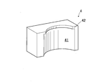
- FIG. 2 is an enlarged perspective view showing the guide portion.
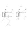
- FIG. 3 is an enlarged view showing the arrangement relationship between the guide portion and the upper portion of the container, wherein (A) shows the position before positioning the container and (B) shows the position after positioning the container.
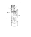
- 4A and 4B are diagrams showing the container, in which FIG. 4A shows a state before putting ice pieces, and FIG. 4B shows a state after putting ice pieces.
- FIG. 5 is a schematic perspective view showing the arrangement relationship between the raw material liquid nozzle, the carbonic acid liquid nozzle, and the inner wall surface of the container.
- FIG. 6A and 6B are schematic views showing the arrangement relationship between the raw material liquid nozzle, the carbonic acid liquid nozzle, and the inner wall surface of the container.
- FIG. 6A is a front view
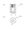
- FIG. FIG. 7 is a view showing an example of a nozzle opening of a raw material liquid nozzle, where (A) is a longitudinal sectional view and (B) is a bottom view.
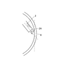
- FIG. 8 is a diagram for explaining the inclination relationship between the discharge direction of the carbonic acid solution nozzle 2 and the inner wall surface of the container.
- FIG. 9 is a diagram illustrating an operation for moving the cartridge reservoir A1 and the carbonic acid solution operating lever 21 to open and close the third valve body provided in the carbonic acid solution dispensing flow path.
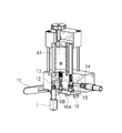
- FIG. 10 shows a standby state in which the raw material liquid is filled in the cartridge reservoir, and the first valve body is closed and the raw material liquid cannot be discharged from the raw material nozzle.
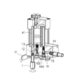
- FIG. 11 shows a state where the second valve body is closed and the first valve body is opened, and the raw material liquid is discharged from the raw material nozzle.
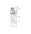
- FIG. 12 shows a state where the first valve body is closed and the second valve body is opened, and the raw material liquid is supplied to the empty cartridge reservoir.
- FIG. 13 shows a high carbonated beverage supply apparatus provided with a nozzle for adding a raw material liquid.
- FIG. 14 is a schematic perspective view showing the arrangement relationship with the inner wall surface of the container when the raw material liquid addition nozzle is provided.
- FIG. 15 is an explanatory diagram of the raw material liquid flow path in the high carbonated beverage supply apparatus A in which the raw material liquid is allowed to flow directly from the raw material liquid tank to the raw material liquid nozzle.
- FIG. 16 is an explanatory diagram of the raw material liquid channel in the embodiment of FIGS.
- the high carbonated beverage supply apparatus A of the present invention performs positioning of a raw material liquid nozzle 1 for pouring a raw material liquid, a carbonic acid liquid nozzle 2 for discharging a carbonic acid liquid, a receiving part 3 for placing a container 6, and a container. And a guide unit 4. After being temporarily placed on the receiving part 3 and then lifted and positioned by the guide part 4, the raw material liquid 1 and the carbonic acid liquid nozzle 2 are used to supply the raw material liquid and carbonic acid, respectively. The liquid can be discharged.
- the raw material liquid is a liquid such as alcohol-containing beverages (for example, whiskey, brandy, shochu, liqueur, etc.), fruit juice, etc.
- the carbonic acid liquid is a liquid for diluting the raw material liquid containing carbon dioxide gas.
- the ice piece 7 (ice block)
- the surface has not been smoothed yet, and the surface with burrs or the like is rough, and various shapes such as a cube, a sphere, and a square are used. Needless to say, an ice piece with a smooth ice surface can also be used.
- the raw material liquid discharged from each nozzle and the carbonic acid liquid are mixed in the container 6 to obtain a high-carbonic beverage liquid.
- FIG. 1 is an overall schematic diagram showing a carbonated beverage server apparatus X equipped with a high carbonated beverage supply apparatus A.
- the carbonated beverage server device X is provided with a high carbonated beverage supply device A on the front surface thereof.
- the high carbonated beverage supply apparatus A includes a raw material liquid nozzle 1 for discharging a raw material liquid and a carbonic acid liquid nozzle 2 for discharging a carbonic acid liquid, and a container 6 is disposed below the nozzles at a predetermined distance.
- a receiving portion 3 to be placed is provided.
- the receiving portion 3 is provided with an eye plate portion 31 having a notch portion for dropping liquid, and the container 6 is temporarily placed on the eye plate portion 31. Moisture adhering to the container 6 and overflowing liquid fall downward from the eye plate part 31 and accumulate in the receiving part 3.
- a guide portion 4 is provided above the receiving portion 3 of the container 6 (below the raw material liquid nozzle 1 and the carbonic acid solution nozzle 2) (see FIG. 1), and when the raw material liquid is discharged, the container 6 is The guide part 4 is positioned at an appropriate position with respect to the raw material liquid nozzle 1 and the carbonic acid liquid nozzle 2.
- FIG. 2 is an enlarged perspective view showing the guide portion 4.
- FIG. 3 is an enlarged view showing the arrangement relationship between the guide part and the upper part of the container.
- FIG. 3A shows a state before positioning the container
- FIG. 3B shows a state after positioning the container.
- the guide portion 4 includes a concave portion 41 that is a portion having a curve corresponding to the shape of the upper side surface of the container 6, and a convex portion 42 that is a portion that covers a part of the upper end portion of the container 6.
- the container 6 temporarily placed on the receiving part 3 is lifted and aligned with the guide part 4 so that the container 6 is positioned at appropriate positions below the raw material liquid nozzle 1 and the carbonic acid liquid nozzle 2 in the vertical and horizontal directions.
- FIG. 4A and 4B are schematic views showing the container 6, in which FIG. 4A shows a state before the ice piece 7 is put, and FIG. 4B shows a state after the ice piece 7 is put.
- FIG. 5 is a schematic perspective view showing an arrangement relationship among the raw material liquid nozzle 1, the carbonic acid liquid nozzle 2, and the inner wall surface of the container 6. In this figure, the guide part is omitted.
- FIG. 6 is a schematic view showing the arrangement relationship between the raw material liquid nozzle 1, the carbonic acid liquid nozzle 2, and the inner wall surface of the container 6.
- FIG. 6A is a front view, and FIG. It shows with.
- the raw material liquid nozzle 1 is connected to a raw material liquid tank (not shown) via a raw material liquid supply flow path, and is disposed so as to be discharged to the center of the positioned container 6.
- the raw material liquid nozzle 1 is provided with the some hole H, and can spray a raw material liquid to the whole ice piece 7 reliably.
- the raw material liquid may be cooled at room temperature (room temperature), or at room temperature, mainly due to the temperature difference between the raw material liquid and ice, and when cooled, due to the reaction heat due to contact between the raw material liquid and ice,
- the ice pieces 7 that have been sprayed with the raw material liquid are not melted with burrs (spine-like splinters) existing on the surface thereof, and the surface becomes uniform and smooth.
- burrs spine-like splinters
- FIG. 7 is a view showing an example of the nozzle opening 1A of the raw material liquid nozzle 1, in which (A) is a longitudinal sectional view, and (B) is a bottom view.
- (A) is a longitudinal sectional view
- (B) is a bottom view.
- eight holes H are provided around the periphery, and a total of nine holes are provided.
- the carbonate solution nozzle 2 is connected to a carbonate solution production tank (not shown), and the carbonate solution cooled from the carbonate solution production tank by moving the carbonate solution operation lever 21 is discharged to the container 6 through the carbonate solution nozzle 2. Supplied.
- the carbonic acid solution nozzle 2 is arranged such that a pipe-like nozzle extends downward and bends along the inner wall surface of the container 6.
- the discharge direction of the carbonic acid solution nozzle 2 (the direction in which the liquid jumps out) is provided so as to incline by a certain angle ⁇ with respect to the horizontal tangential direction of the inner wall surface of the opposing container 6.
- the angle ⁇ refers to an angle formed by the tangential direction at the intersection of the central axis of the carbonic acid solution nozzle 2 and the inner wall surface.
- FIG. 8 is a view for explaining the inclination relationship between the discharge direction of the carbonic acid solution nozzle 2 and the inner wall surface of the container 6.
- the inclination angle ⁇ is less than 90 degrees, but from the viewpoint of suppressing the generation of carbon dioxide bubbles as much as possible, for example, 10 to 70 degrees is preferably employed.
- FIG. 9 is an explanatory diagram of the cartridge reservoir A1 that temporarily stores the raw material liquid, which is provided in the high carbonated beverage supply apparatus A of the present invention.
- the cartridge reservoir A1 is connected to a raw material liquid tank (not shown) via the raw material liquid supply channel 14, and the raw material liquid is additionally supplied from the raw material liquid tank to the cartridge reservoir A1. Further, the cartridge reservoir A1 is connected to the raw material liquid nozzle 1 via the raw material liquid discharge channel 12, and a fixed amount (one shot) of the raw material liquid W is filled in the cartridge reservoir A1. By moving the raw material liquid operation lever 11, the liquid is discharged into the container 6 through the raw material liquid nozzle 1. When the cartridge reservoir A1 becomes empty (colored), the raw material liquid is filled into the cartridge reservoir A1 from the raw material liquid tank through the raw material liquid supply channel 14 by a fixed amount (one shot). It has become.
- FIG. 9 is a diagram for explaining an operation for opening and closing the third valve body 23 provided in the carbonic acid solution dispensing flow path 22 by moving the carbonic acid solution operating lever 21.
- (A) shows a state (standby state) where the third valve body 23 cannot be discharged
- (B) shows a state where the third valve body 23 is opened and can discharge the carbonic acid solution. Note that the structure for transmitting the movement of the carbonic acid solution operating lever 21 to the third valve body 23 is omitted.
- the vertical carbonic acid solution operating lever 21 is moved and leveled, the closed third valve body 23 is opened, and the carbonic acid liquid discharge passage 22 can be passed. Therefore, the carbonic acid solution is discharged from the carbonic acid solution nozzle 2.
- the cartridge reservoir A1 is connected to the raw material liquid tank, and the raw material liquid is filled from the raw material liquid tank through the raw material liquid supply flow path into the cartridge reservoir A1 by a certain amount (one shot).
- One-shot is the amount of raw liquid required for the production of high carbonated beverages for a full container, which is often 30 ml, 45 ml, 60 ml, etc., but is set appropriately depending on the type of raw material liquid and the type of high carbonated beverage you want to make Is done.
- a predetermined amount (one shot) of the raw material liquid is discharged from the cartridge reservoir A1 to the container 6 through the raw material liquid nozzle 1.
- a valve switching safety mechanism is provided between the raw material liquid supply flow path 14 from the raw material liquid tank to the cartridge reservoir A1 and the raw material liquid extraction flow path 12 that guides the raw material liquid filled in the cartridge reservoir A1 and pours it out.
- FIGS. 10 to 12 are internal sectional views of a partial cross section for explaining the valve switching safety mechanism.
- the cover body A1a covering the cartridge reservoir A1 is omitted for convenience.
- FIG. 10 shows a state (standby state) in which the raw material liquid is filled in the cartridge reservoir A1, and the first valve body 13 is closed and the raw material liquid cannot be discharged from the raw material nozzle.
- FIG. 11 shows a state where the second valve body 15 is closed and the first valve body 13 is opened, and the raw material liquid is discharged from the raw material nozzle 1.
- FIG. 12 shows a state where the first valve body 13 is closed and the second valve body 15 is opened, and the raw material liquid is supplied to the empty cartridge reservoir A1.
- a first valve body 13 is provided in the raw material liquid extraction flow path 12 which is a flow path for discharging the raw material liquid filled in the cartridge storage device A1 to the outside.
- a second valve body 15 is provided in the raw material liquid supply flow path 14 which is a flow path for supplying the raw material liquid.
- a cam rod 16 is provided in common for making these passages passable or not passable, that is, for opening and closing each valve body.
- the cam rod 16 slides in the horizontal direction, and opens and closes the first valve body 13 and the second valve body 15. Specifically, the cam rod 16 is in perpendicular contact with the first valve body 13 and the second valve body 15, and the first valve body 13 and the second valve body 15 are opened and closed synchronously by the movement of the cam rod 16. be able to.
- the first valve body 13 is normally biased downward by a spring so that the flow path cannot pass through, but has a structure that opens when the spring is overcome and pushed up.
- the second valve body 15 is normally biased downward by a spring so that the flow path can pass therethrough. However, the second valve body 15 has a structure that closes when the spring is overcome and pushed up.
- the raw material liquid supply flow path 14 can pass, the raw material liquid is supplied again to the emptied cartridge reservoir A1 until a predetermined amount (one shot) is obtained (see FIG. 12).
- the pressure for supplying the raw material liquid depends on the pressure of the flow jet pump, for example.
- the first valve body 13 is closed, the raw material liquid is not discharged from the raw material liquid nozzle 1.
- the first valve body 13 is opened after the second valve body 15 is closed by the forward movement of the cam rod 16, and the first valve body is opened by the reverse movement of the cam rod 16.
- the second valve body 15 opens after 13 is closed.
- the raw material liquid is not supplied to the cartridge reservoir A1, and the raw material liquid for one shot is poured accurately into the container 6.
- the raw material liquid is not inadvertently supplied to the cartridge reservoir A ⁇ b> 1, and this prevents the raw material liquid from being excessively injected into the container 6. Is done.
- the raw material liquid can be poured into the container 6 with peace of mind. Incidentally, in order to change a certain amount (one shot) of the cartridge reservoir A1, it is performed by changing the volume of the internal space, but the details are omitted.
- the raw material liquid is discharged into the container 6 containing the ice pieces 7 while being in contact with the ice pieces 7 (raw material liquid discharge), and then the carbonic acid solution is brought into contact with the inner wall surface of the container 6. Discharge while discharging (carbonic acid solution discharge).
- the key point for producing a highly carbonated beverage, that is, the trick is to discharge the carbonated liquid after discharging the raw material liquid.
- the container 6 Temporarily place the container 6 containing the ice pieces 7 on the receiving part 3.
- the container 6 is properly positioned in the vertical and horizontal directions, the raw material liquid nozzle 1 is positioned above the central part of the container 6, and the carbonic acid liquid nozzle 2 is 6 along the inner wall surface.
- the discharge direction of the carbonic acid solution nozzle 2 is arranged to be inclined by an angle ⁇ with respect to the horizontal tangential direction of the inner wall surface of the container 6 (see FIG. 8).
- the raw material liquid operation lever 11 is operated to discharge the raw material liquid (whiskey or the like) from the raw material liquid nozzle 1.
- the discharged raw material liquid falls on the ice piece 7 in the container 6 and first smoothes the rough surface of the ice piece 7. That is, burrs and the like on the surface of the ice piece 7 are eliminated to make a smooth surface. This eliminates the carbon dioxide escape factor 1 described above. Since the raw material liquid nozzle 1 is located at the center of the container 6, the raw material liquid falls evenly on the entire ice piece 7, and since the raw material liquid nozzle 1 has a plurality of holes, the raw material liquid is iced. The whole piece 7 is sprayed.
- the carbonated liquid operation lever 21 is moved to discharge the carbonated liquid from the carbonated liquid nozzle 2, and the carbonated liquid flows along the inner wall surface of the container 6. Moreover, since the discharge direction of the carbonic acid solution nozzle 2 is inclined by an angle ⁇ with respect to the horizontal tangential direction of the inner wall surface of the container 6, there is no impact and the carbon dioxide gas does not escape. This eliminates the carbon dioxide escape factor 2 described above. Thus, the carbonic acid solution does not collide with the inner wall surface of the container 6 in an impact manner, and does not fall directly on the ice piece 7 as much as possible.
- the present invention has been described above, the present invention is not limited to the embodiments, and various modifications can be made.
- another raw material liquid nozzle for adjusting the concentration so as to meet the taste of a person who drinks a carbonated beverage.
- the amount of the raw material liquid for one shot is regulated, so that it is not possible when a thick carbonated beverage is required according to customer preference.
- Such a case can be dealt with by providing a raw material liquid addition nozzle (connected to the raw material liquid tank) for further adding an additional raw material liquid to thicken the carbonated beverage.
- FIG. 13 shows a supply device A for a high carbonated beverage provided with a nozzle 5 for adding a raw material liquid.
- FIG. 14 is a schematic perspective view showing the arrangement relationship with the inner wall surface of the container 6 when the raw material liquid addition nozzle 5 is provided. Therefore, for a person who prefers a beverage with a high concentration of the raw material liquid, an additional raw material liquid is added to the container 6 by operating the operation lever (not shown) of the raw material liquid adding nozzle 5.
- the addition of the addition raw material liquid from the raw material liquid addition nozzle 5 may be after the above-described raw material liquid discharge or after the carbonic acid liquid discharge.
- the supply apparatus of the high carbonated beverages shown in FIG.13 and FIG.14 is equipped with cartridge storage device A1, and has the function to discharge the raw material liquid for one shot in a container in principle. Therefore, three nozzles of the raw material liquid nozzle 1, the raw material liquid addition nozzle 5, and the carbonic acid liquid nozzle 2 are required. By supplying the raw material liquid directly from the raw material liquid tank T to the raw material liquid nozzle 1 without providing the cartridge reservoir A1, the number of nozzles can be reduced.
- FIG. 15 is an explanatory diagram of the raw material liquid flow path in the high carbonated beverage supply apparatus A in which the raw material liquid is allowed to flow directly from the raw material liquid tank T to the raw material liquid nozzle 1.
- a raw material liquid supply passage 14A is provided between the raw material liquid tank T and the raw material liquid nozzle 1, and a valve body 13A is provided in the raw material liquid supply passage 14A.
- the amount of the raw material liquid discharged to the container can be increased or decreased or freely adjusted by using the valve body 13A as an electromagnetic valve and opening and closing by switching the switch.
- the electromagnetic valve is switched by electric drive, it is naturally possible to set the raw material liquid so as to have a constant discharge amount.
- valve body 13A can be opened and closed by mechanical drive by moving the raw material liquid operation lever.
- the amount of the raw material liquid discharged to the container can be increased or decreased or freely adjusted by operating the raw material liquid operation lever.
- the high carbonated beverage supply device A has been described as an example, but it is naturally also possible to design a plurality of so-called nozzle towers (supports).
- FIG. 1 For reference, an explanatory diagram of the raw material liquid flow path in the embodiment of FIGS. 1 to 12 is shown in FIG.
- the high carbonated beverage supply device of the present invention is provided such that the raw material liquid nozzle is positioned at the center of the container, the nozzle hole of the carbonate liquid nozzle is disposed along the inner wall surface of the container, and the carbonated liquid Is discharged so as to be inclined at an angle ⁇ with respect to the horizontal tangential direction of the inner wall surface, so that the raw material liquid is applied evenly to the entire ice pieces in the container. Further, the carbonic acid solution does not directly collide with the inner wall surface of the container, and the carbon dioxide contained in the carbonated water is difficult to escape. As long as this principle can be used, it can be widely used in a discharge device for a liquid containing gas.
Landscapes
- Devices For Dispensing Beverages (AREA)
- Containers And Packaging Bodies Having A Special Means To Remove Contents (AREA)
Abstract
Priority Applications (3)
| Application Number | Priority Date | Filing Date | Title |
|---|---|---|---|
| JP2016535765A JP6595994B2 (ja) | 2014-07-23 | 2015-06-19 | 高炭酸飲料の供給装置 |
| CN201580038108.2A CN106660772B (zh) | 2014-07-23 | 2015-06-19 | 高碳酸饮料的供给装置 |
| KR1020167036272A KR102363517B1 (ko) | 2014-07-23 | 2015-06-19 | 고탄산 음료의 공급 장치 |
Applications Claiming Priority (2)
| Application Number | Priority Date | Filing Date | Title |
|---|---|---|---|
| JP2014150250 | 2014-07-23 | ||
| JP2014-150250 | 2014-07-23 |
Publications (1)
| Publication Number | Publication Date |
|---|---|
| WO2016013151A1 true WO2016013151A1 (fr) | 2016-01-28 |
Family
ID=55162700
Family Applications (1)
| Application Number | Title | Priority Date | Filing Date |
|---|---|---|---|
| PCT/JP2015/003094 Ceased WO2016013151A1 (fr) | 2014-07-23 | 2015-06-19 | Dispositif de distribution de boisson très gazeuse |
Country Status (4)
| Country | Link |
|---|---|
| JP (1) | JP6595994B2 (fr) |
| KR (1) | KR102363517B1 (fr) |
| CN (1) | CN106660772B (fr) |
| WO (1) | WO2016013151A1 (fr) |
Families Citing this family (3)
| Publication number | Priority date | Publication date | Assignee | Title |
|---|---|---|---|---|
| CN111700502A (zh) * | 2019-03-18 | 2020-09-25 | 富士电机株式会社 | 饮料供给装置 |
| KR102222670B1 (ko) | 2020-07-23 | 2021-03-04 | 김태헌 | 하이볼 제조 및 디스펜싱 시스템 |
| KR102838002B1 (ko) * | 2024-10-29 | 2025-07-24 | (주)위벨롭먼트 | 저온 숙성 살얼음 맥주 공급 장치 |
Citations (7)
| Publication number | Priority date | Publication date | Assignee | Title |
|---|---|---|---|---|
| JPH02108900U (fr) * | 1989-02-13 | 1990-08-29 | ||
| JP2000025899A (ja) * | 1998-07-10 | 2000-01-25 | Fuji Electric Co Ltd | 飲料ディスペンサの飲料供給ノズル |
| JP2003137396A (ja) * | 2001-11-07 | 2003-05-14 | Sanyo Electric Co Ltd | 飲料供給装置 |
| JP2003160196A (ja) * | 2001-11-22 | 2003-06-03 | Sanyo Electric Co Ltd | 飲料供給装置 |
| WO2003045832A1 (fr) * | 2001-11-30 | 2003-06-05 | Labatt Brewing Company Limited | Systeme et dispositif de distribution de boissons |
| JP3179224U (ja) * | 2012-08-09 | 2012-10-18 | 富士電機リテイルシステムズ株式会社 | 飲料供給装置 |
| US20130255825A1 (en) * | 2012-04-03 | 2013-10-03 | David J. Fedewa | Foam reducing container |
Family Cites Families (10)
| Publication number | Priority date | Publication date | Assignee | Title |
|---|---|---|---|---|
| JPS56145781U (fr) * | 1980-03-26 | 1981-11-04 | ||
| JPH0330320Y2 (fr) * | 1986-02-20 | 1991-06-26 | ||
| JP3939011B2 (ja) * | 1998-03-30 | 2007-06-27 | 三洋電機株式会社 | 飲料供給装置 |
| JP2001106299A (ja) * | 1999-10-06 | 2001-04-17 | Sanden Corp | 炭酸飲料供給装置 |
| JP2001171796A (ja) | 1999-12-14 | 2001-06-26 | Fuji Electric Co Ltd | 飲料ディスペンサ |
| DK1611944T3 (da) * | 2003-03-28 | 2009-11-16 | Suntory Holdings Ltd | Opbevaringsudstyr med en afgangsmekanisme til fast stof |
| JP2007045496A (ja) * | 2005-08-12 | 2007-02-22 | Fuji Electric Retail Systems Co Ltd | 飲料供給装置 |
| JP5617351B2 (ja) * | 2010-05-28 | 2014-11-05 | 富士電機株式会社 | 飲料供給装置 |
| JP5659719B2 (ja) * | 2010-11-12 | 2015-01-28 | 大日本印刷株式会社 | 液化ガス添加用ノズル |
| US8485503B2 (en) * | 2011-04-14 | 2013-07-16 | Skip A. Lei | Multi stream wine aerating device |
-
2015
- 2015-06-19 WO PCT/JP2015/003094 patent/WO2016013151A1/fr not_active Ceased
- 2015-06-19 JP JP2016535765A patent/JP6595994B2/ja active Active
- 2015-06-19 CN CN201580038108.2A patent/CN106660772B/zh active Active
- 2015-06-19 KR KR1020167036272A patent/KR102363517B1/ko active Active
Patent Citations (7)
| Publication number | Priority date | Publication date | Assignee | Title |
|---|---|---|---|---|
| JPH02108900U (fr) * | 1989-02-13 | 1990-08-29 | ||
| JP2000025899A (ja) * | 1998-07-10 | 2000-01-25 | Fuji Electric Co Ltd | 飲料ディスペンサの飲料供給ノズル |
| JP2003137396A (ja) * | 2001-11-07 | 2003-05-14 | Sanyo Electric Co Ltd | 飲料供給装置 |
| JP2003160196A (ja) * | 2001-11-22 | 2003-06-03 | Sanyo Electric Co Ltd | 飲料供給装置 |
| WO2003045832A1 (fr) * | 2001-11-30 | 2003-06-05 | Labatt Brewing Company Limited | Systeme et dispositif de distribution de boissons |
| US20130255825A1 (en) * | 2012-04-03 | 2013-10-03 | David J. Fedewa | Foam reducing container |
| JP3179224U (ja) * | 2012-08-09 | 2012-10-18 | 富士電機リテイルシステムズ株式会社 | 飲料供給装置 |
Also Published As
| Publication number | Publication date |
|---|---|
| JP6595994B2 (ja) | 2019-10-23 |
| CN106660772B (zh) | 2019-05-14 |
| JPWO2016013151A1 (ja) | 2017-04-27 |
| KR20170038766A (ko) | 2017-04-07 |
| KR102363517B1 (ko) | 2022-02-16 |
| CN106660772A (zh) | 2017-05-10 |
Similar Documents
| Publication | Publication Date | Title |
|---|---|---|
| JP3179224U (ja) | 飲料供給装置 | |
| TW201520143A (zh) | 噴流裝置 | |
| JP6595994B2 (ja) | 高炭酸飲料の供給装置 | |
| JP6595995B2 (ja) | 高炭酸飲料の供給方法 | |
| US20160220970A1 (en) | Method and Apparatus for Rapid Carbonation of a Fluid | |
| JP2014023979A (ja) | 炭酸水製造装置 | |
| JP4859757B2 (ja) | 発泡性飲料サーバー | |
| JP6713228B2 (ja) | 液体注出装置 | |
| JP5672777B2 (ja) | 飲料供給装置の飲料ノズル | |
| JP7307626B2 (ja) | 飲料自動注出装置 | |
| JP6511335B2 (ja) | 発泡性飲料自動注出装置 | |
| JP6088416B2 (ja) | 飲料の製造方法、及び飲料 | |
| JP2016059372A (ja) | 容器入りコーヒー飲料、容器入りコーヒー飲料の製造方法、コーヒー用ディスペンサーおよびコーヒーサーバー装置 | |
| JP7321831B2 (ja) | 炭酸飲料用注出ノズル | |
| JP7633050B2 (ja) | 飲料サーバー | |
| TWI748658B (zh) | 飲料機及注出構件 | |
| JP2006016048A (ja) | 飲料注出バルブ | |
| JP6636382B2 (ja) | 炭酸飲料の注出装置 | |
| WO2020138099A1 (fr) | Dispositif de versement de boisson effervescente | |
| KR101331508B1 (ko) | 알콜 및 탄산음료병 마개 | |
| WO2026053868A1 (fr) | Dispositif de production d'eau gazeuse et procédé de production d'eau gazeuse l'utilisant | |
| JP2021054534A (ja) | 飲料サーバー及び注出部材 | |
| CN105520642B (zh) | 饮料供应装置的多路阀 | |
| JP2017197254A (ja) | 飲料充填装置 | |
| KR20170085350A (ko) | 생맥주 인출밸브 |
Legal Events
| Date | Code | Title | Description |
|---|---|---|---|
| 121 | Ep: the epo has been informed by wipo that ep was designated in this application |
Ref document number: 15825426 Country of ref document: EP Kind code of ref document: A1 |
|
| ENP | Entry into the national phase |
Ref document number: 20167036272 Country of ref document: KR Kind code of ref document: A |
|
| ENP | Entry into the national phase |
Ref document number: 2016535765 Country of ref document: JP Kind code of ref document: A |
|
| NENP | Non-entry into the national phase |
Ref country code: DE |
|
| 122 | Ep: pct application non-entry in european phase |
Ref document number: 15825426 Country of ref document: EP Kind code of ref document: A1 |