WO2016013226A1 - Système de commande de moteur à combustion interne - Google Patents
Système de commande de moteur à combustion interne Download PDFInfo
- Publication number
- WO2016013226A1 WO2016013226A1 PCT/JP2015/003703 JP2015003703W WO2016013226A1 WO 2016013226 A1 WO2016013226 A1 WO 2016013226A1 JP 2015003703 W JP2015003703 W JP 2015003703W WO 2016013226 A1 WO2016013226 A1 WO 2016013226A1
- Authority
- WO
- WIPO (PCT)
- Prior art keywords
- fuel ratio
- air
- rich
- lean
- output
- Prior art date
- Legal status (The legal status is an assumption and is not a legal conclusion. Google has not performed a legal analysis and makes no representation as to the accuracy of the status listed.)
- Ceased
Links
Images








Classifications
-
- F—MECHANICAL ENGINEERING; LIGHTING; HEATING; WEAPONS; BLASTING
- F02—COMBUSTION ENGINES; HOT-GAS OR COMBUSTION-PRODUCT ENGINE PLANTS
- F02D—CONTROLLING COMBUSTION ENGINES
- F02D41/00—Electrical control of supply of combustible mixture or its constituents
- F02D41/02—Circuit arrangements for generating control signals
- F02D41/021—Introducing corrections for particular conditions exterior to the engine
- F02D41/0235—Introducing corrections for particular conditions exterior to the engine in relation with the state of the exhaust gas treating apparatus
- F02D41/0295—Control according to the amount of oxygen that is stored on the exhaust gas treating apparatus
-
- F—MECHANICAL ENGINEERING; LIGHTING; HEATING; WEAPONS; BLASTING
- F01—MACHINES OR ENGINES IN GENERAL; ENGINE PLANTS IN GENERAL; STEAM ENGINES
- F01N—GAS-FLOW SILENCERS OR EXHAUST APPARATUS FOR MACHINES OR ENGINES IN GENERAL; GAS-FLOW SILENCERS OR EXHAUST APPARATUS FOR INTERNAL-COMBUSTION ENGINES
- F01N11/00—Monitoring or diagnostic devices for exhaust-gas treatment apparatus
- F01N11/007—Monitoring or diagnostic devices for exhaust-gas treatment apparatus the diagnostic devices measuring oxygen or air concentration downstream of the exhaust apparatus
-
- F—MECHANICAL ENGINEERING; LIGHTING; HEATING; WEAPONS; BLASTING
- F02—COMBUSTION ENGINES; HOT-GAS OR COMBUSTION-PRODUCT ENGINE PLANTS
- F02D—CONTROLLING COMBUSTION ENGINES
- F02D41/00—Electrical control of supply of combustible mixture or its constituents
- F02D41/02—Circuit arrangements for generating control signals
- F02D41/14—Introducing closed-loop corrections
- F02D41/1438—Introducing closed-loop corrections using means for determining characteristics of the combustion gases; Sensors therefor
- F02D41/1439—Introducing closed-loop corrections using means for determining characteristics of the combustion gases; Sensors therefor characterised by the position of the sensor
- F02D41/1441—Plural sensors
-
- F—MECHANICAL ENGINEERING; LIGHTING; HEATING; WEAPONS; BLASTING
- F02—COMBUSTION ENGINES; HOT-GAS OR COMBUSTION-PRODUCT ENGINE PLANTS
- F02D—CONTROLLING COMBUSTION ENGINES
- F02D41/00—Electrical control of supply of combustible mixture or its constituents
- F02D41/02—Circuit arrangements for generating control signals
- F02D41/14—Introducing closed-loop corrections
- F02D41/1438—Introducing closed-loop corrections using means for determining characteristics of the combustion gases; Sensors therefor
- F02D41/1444—Introducing closed-loop corrections using means for determining characteristics of the combustion gases; Sensors therefor characterised by the characteristics of the combustion gases
- F02D41/1454—Introducing closed-loop corrections using means for determining characteristics of the combustion gases; Sensors therefor characterised by the characteristics of the combustion gases the characteristics being an oxygen content or concentration or the air-fuel ratio
-
- F—MECHANICAL ENGINEERING; LIGHTING; HEATING; WEAPONS; BLASTING
- F02—COMBUSTION ENGINES; HOT-GAS OR COMBUSTION-PRODUCT ENGINE PLANTS
- F02D—CONTROLLING COMBUSTION ENGINES
- F02D41/00—Electrical control of supply of combustible mixture or its constituents
- F02D41/02—Circuit arrangements for generating control signals
- F02D41/14—Introducing closed-loop corrections
- F02D41/1438—Introducing closed-loop corrections using means for determining characteristics of the combustion gases; Sensors therefor
- F02D41/1493—Details
- F02D41/1495—Detection of abnormalities in the air/fuel ratio feedback system
-
- F—MECHANICAL ENGINEERING; LIGHTING; HEATING; WEAPONS; BLASTING
- F02—COMBUSTION ENGINES; HOT-GAS OR COMBUSTION-PRODUCT ENGINE PLANTS
- F02D—CONTROLLING COMBUSTION ENGINES
- F02D41/00—Electrical control of supply of combustible mixture or its constituents
- F02D41/24—Electrical control of supply of combustible mixture or its constituents characterised by the use of digital means
-
- F—MECHANICAL ENGINEERING; LIGHTING; HEATING; WEAPONS; BLASTING
- F02—COMBUSTION ENGINES; HOT-GAS OR COMBUSTION-PRODUCT ENGINE PLANTS
- F02D—CONTROLLING COMBUSTION ENGINES
- F02D41/00—Electrical control of supply of combustible mixture or its constituents
- F02D41/24—Electrical control of supply of combustible mixture or its constituents characterised by the use of digital means
- F02D41/2406—Electrical control of supply of combustible mixture or its constituents characterised by the use of digital means using essentially read only memories
- F02D41/2425—Particular ways of programming the data
- F02D41/2429—Methods of calibrating or learning
- F02D41/2451—Methods of calibrating or learning characterised by what is learned or calibrated
- F02D41/2454—Learning of the air-fuel ratio control
-
- F—MECHANICAL ENGINEERING; LIGHTING; HEATING; WEAPONS; BLASTING
- F02—COMBUSTION ENGINES; HOT-GAS OR COMBUSTION-PRODUCT ENGINE PLANTS
- F02D—CONTROLLING COMBUSTION ENGINES
- F02D2200/00—Input parameters for engine control
- F02D2200/02—Input parameters for engine control the parameters being related to the engine
- F02D2200/08—Exhaust gas treatment apparatus parameters
- F02D2200/0814—Oxygen storage amount
-
- F—MECHANICAL ENGINEERING; LIGHTING; HEATING; WEAPONS; BLASTING
- F02—COMBUSTION ENGINES; HOT-GAS OR COMBUSTION-PRODUCT ENGINE PLANTS
- F02D—CONTROLLING COMBUSTION ENGINES
- F02D2200/00—Input parameters for engine control
- F02D2200/02—Input parameters for engine control the parameters being related to the engine
- F02D2200/08—Exhaust gas treatment apparatus parameters
- F02D2200/0816—Oxygen storage capacity
Definitions
- the present invention relates to a control system of an internal combustion engine.
- a control system of an internal combustion engine which is provided with an air-fuel ratio sensor in an exhaust passage of an internal combustion engine and controls the amount of fuel which is fed to the internal combustion engine based on an output of the air-fuel ratio sensor, has been widely known.
- a control system one which is provided with an air-fuel ratio sensor at an upstream side of an exhaust purification catalyst which is provided in an engine exhaust passage and with an oxygen sensor at a downstream side, has been proposed (for example, PTL 1).
- the air-fuel ratio of the exhaust gas flowing into the exhaust purification catalyst is controlled so that the oxygen storage amount of the exhaust purification catalyst becomes a certain target value.
- the oxygen storage amount of the exhaust purification catalyst is larger than a target value, feedback control is performed so that the output air-fuel ratio of the upstream side air-fuel ratio sensor becomes an air-fuel ratio which is richer than the stoichiometric air-fuel ratio (below, referred to as "rich air-fuel ratio").
- the output of the downstream side oxygen sensor indicates a rich air-fuel ratio or lean air-fuel ratio for a given time period
- the output of the upstream side air-fuel ratio sensor is corrected. Accordingly, it is considered that even if there is error in the output of the upstream side air-fuel ratio sensor, the oxygen storage amount of the exhaust purification catalyst can be made to match with the target value.
- a control system which performs control different from the control system described in the above PTL 1, is proposed.
- the target air-fuel ratio is set to an air-fuel ratio which is leaner than the stoichiometric air-fuel ratio (below, referred to as "lean air-fuel ratio").
- the target air-fuel ratio is changed smaller in lean degree one time while being set to the lean air-fuel ratio.
- the target air-fuel ratio which is detected by the downstream side air-fuel ratio sensor is the lean judged air-fuel ratio (air-fuel ratio which is slightly leaner than the stoichiometric air-fuel ratio) or more
- the target air-fuel ratio is set to an air-fuel ratio which is richer than the stoichiometric air-fuel ratio (below, referred to as "rich air-fuel ratio").
- the target air-fuel ratio is changed smaller in rich degree one time while being set to the rich air-fuel ratio. That is, in this control system, the target air-fuel ratio is alternately switched between the rich air-fuel ratio and the lean air-fuel ratio.
- an object of the present invention is to provide a control system of an internal combustion engine, which performs control of the target air-fuel ratio as explained above wherein even if deviation occurs in the output value of the upstream side air-fuel ratio sensor, etc., that deviation can be suitably compensated for.
- a control system of internal combustion engine which engine comprises: an exhaust purification catalyst which is arranged in an exhaust passage of an internal combustion engine and which can store oxygen; and a downstream side air-fuel ratio sensor which is arranged at a downstream side, in the direction of exhaust flow, of the exhaust purification catalyst and which detects the air-fuel ratio of the exhaust gas flowing out from the exhaust purification catalyst, the control system of an internal combustion engine performs feedback control of the feed amount of fuel which is fed to a combustion chamber of the internal combustion engine so that an air-fuel ratio of exhaust gas flowing into the exhaust purification catalyst becomes a target air-fuel ratio, and performs learning control which corrects a parameter relating to the feedback control based on the output air-fuel ratio of the downstream side air-fuel ratio sensor, wherein the target air-fuel ratio is switched from a rich air-fuel ratio which is richer than the stoichiometric air-fuel ratio to a lean air-fuel ratio which is leaner than the s
- the target air-fuel ratio is switched from the rich air-fuel ratio to a lean set air-fuel ratio which is leaner than the stoichiometric air-fuel ratio, when the output air-fuel ratio of the downstream side air-fuel ratio sensor becomes the rich judged air-fuel ratio or less, the target air-fuel ratio is set to a lean air-fuel ratio which is smaller in lean degree than the lean set air-fuel ratio, from the lean degree changing timing after the target air-fuel ratio is set to the lean set air-fuel ratio and before the output air-fuel ratio of the downstream side air-fuel ratio sensor becomes the lean judged air-fuel ratio or more, to when the output air-fuel ratio of the downstream side air-fuel ratio sensor becomes the lean judged air-fuel ratio or more, the target air-fuel ratio is switched from the lean air-fuel ratio to a rich set air-fuel ratio which is richer than the stoichiometric air-fuel ratio,
- the first or second aspect of the invention wherein the stoichiometric air-fuel ratio judgment time is not less than the time until the absolute value of the oxygen excess/deficiency which is cumulatively added from when the target air-fuel ratio is switched to an air-fuel ratio which is deviated from the stoichiometric air-fuel ratio to said one side, reaches a maximum storable oxygen amount of the exhaust purification catalyst which is unused.
- any one of the first to third aspects of the invention wherein in the learning control, when the target air-fuel ratio is set to a rich air-fuel ratio, if the output air-fuel ratio of the downstream side air-fuel ratio sensor is maintained at an air-fuel ratio which is leaner than the lean judged air-fuel ratio for the rich/lean air-fuel ratio judgment time or more, lean stuck learning is performed which corrects a parameter relating to the feedback control so that the air-fuel ratio of the exhaust gas flowing into the exhaust purification catalyst changes to the rich side.
- a correction amount in the lean stuck learning is larger than a correction amount in the stoichiometric air-fuel ratio stuck learning.
- any one of the first to fifth aspects of the invention wherein in the learning control, when the target air-fuel ratio is set to a lean air-fuel ratio, if the output air-fuel ratio of the downstream side air-fuel ratio sensor is maintained at an air-fuel ratio which is richer than the rich judged air-fuel ratio for the rich/lean air-fuel ratio judgment time or more, rich stuck learning is performed which corrects a parameter relating to the feedback control so that the air-fuel ratio of the exhaust gas flowing into the exhaust purification catalyst changes to the lean side.
- a correction amount in the rich stuck learning is larger than a correction amount in the stoichiometric air-fuel ratio stuck learning.
- any one of the fourth to seventh aspects of the invention wherein the rich/lean air-fuel ratio judgment time is shorter than the stoichiometric air-fuel ratio judgment time.
- any one of the fourth to eight aspects of the invention wherein the rich/lean air-fuel ratio judgment time is changed in accordance with an amount of flow of exhaust gas which is cumulatively added from when the target air-fuel ratio is switched between the rich air-fuel ratio and the lean air-fuel ratio.
- any one of the fourth or ninth aspect of the invention wherein the rich/lean air-fuel ratio judgment time is not less than a response delay time of the downstream side air-fuel ratio sensor which is taken from when switching the target air-fuel ratio to when the output air-fuel ratio of the downstream side air-fuel ratio sensor changes according to the switch.
- any one of the first to tenth aspects of the invention wherein in the learning control, a normal learning control is performed in which a parameter relating to feedback control is corrected, based on a first oxygen amount cumulative value which is an absolute value of cumulative oxygen excess/deficiency in a first time period from when switching the target air-fuel ratio to the lean air-fuel ratio to when the output air-fuel ratio of the downstream side air-fuel ratio sensor becomes the lean judged air-fuel ratio or more, and a second oxygen amount cumulative value which is an absolute value of cumulative oxygen excess/deficiency in a second time period from when switching the target air-fuel ratio to the rich air-fuel ratio to when the output air-fuel ratio of the downstream side air-fuel ratio sensor becomes the rich judged air-fuel ratio or less, so that the difference between these first oxygen amount cumulative value and second oxygen amount cumulative value becomes smaller.
- a first oxygen amount cumulative value which is an absolute value of cumulative oxygen excess/deficiency in a first time period from when switching the target air-fuel ratio to the lean air-
- any one of the first to 11th aspects of the invention wherein the parameter relating to feedback control is either of the target air-fuel ratio, fuel feed amount, and air-fuel ratio serving the center of control.
- the engine further comprises an upstream side air-fuel ratio sensor which is arranged at an upstream side, in the direction of exhaust flow, of the exhaust purification catalyst and which detects the air-fuel ratio of exhaust gas flowing into the exhaust purification catalyst, wherein the amount of feed of fuel which is fed to the combustion chamber of the internal combustion engine is feedback controlled so that the output air-fuel ratio of the upstream side air-fuel ratio sensor becomes a target air-fuel ratio, and the parameter relating to the feedback control is the output value of the upstream side air-fuel ratio sensor.
- a control system of an internal combustion engine wherein even if deviation occurs in the output value of the upstream side air-fuel ratio sensor, etc., that deviation can be suitably compensated for.
- FIG. 1 is a view which schematically shows an internal combustion engine in which a control device of the present invention is used.
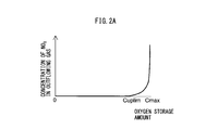
- FIG. 2A is a view which shows the relationship between the oxygen storage amount of the exhaust purification catalyst and concentration of NO X in the exhaust gas which flows out from the exhaust purification catalyst.
- FIG. 2B is a view which shows the relationship between the oxygen storage amount of the exhaust purification catalyst and concentration of HC or CO in the exhaust gas which flows out from the exhaust purification catalyst.
- FIG. 3 is a view which shows the relationship between the voltage supplied to the sensor and output current at different exhaust air-fuel ratios.
- FIG. 4 is a view which shows the relationship between the exhaust air-fuel ratio and output current when making the voltage supplied to the sensor constant.
- FIG. 2A is a view which shows the relationship between the oxygen storage amount of the exhaust purification catalyst and concentration of NO X in the exhaust gas which flows out from the exhaust purification catalyst.
- FIG. 2B is a view which shows the relationship between the oxygen storage amount of the exhaust purification catalyst
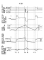
- FIG. 5 is a time chart of air-fuel ratio adjustment amount, etc., when performing basic air-fuel ratio control by the control system of an internal combustion engine according to the present embodiment.
- FIG. 6 is a time chart of air-fuel ratio adjustment amount, etc., when a deviation occurs in the output air-fuel ratio of the upstream side air-fuel ratio sensor.
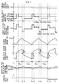
- FIG. 7 is a time chart of air-fuel ratio adjustment amount, etc., when performing normal learning control.
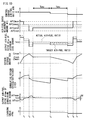
- FIG. 8 is a time chart of air-fuel ratio adjustment amount, etc., when a large deviation occurs in the output air-fuel ratio of the upstream side air-fuel ratio sensor.
- FIG. 6 is a time chart of air-fuel ratio adjustment amount, etc., when a deviation occurs in the output air-fuel ratio of the upstream side air-fuel ratio sensor.
- FIG. 9 is a time chart of air-fuel ratio adjustment amount, etc., when a large deviation occurs in the output air-fuel ratio of the upstream side air-fuel ratio sensor.
- FIG. 10 is a time chart of the air-fuel ratio adjustment amount, etc., when performing stoichiometric air-fuel ratio stuck learning.
- FIG. 11 is a time chart of air-fuel ratio adjustment amount etc. when performing lean stuck learning, etc.
- FIG. 12 is a functional block diagram of a control device.
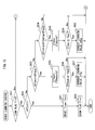
- FIG. 13 is a flow chart which shows a control routine of control for calculation of an air-fuel ratio adjustment amount.
- FIG. 14 is a flow chart which shows a control routine of normal learning control.
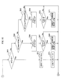
- FIG. 15 is part of a flow chart which shows a control routine of stuck learning control.
- FIG. 16 is part of a flow chart which shows a control routine of stuck learning control.
- FIG. 1 is a view which schematically shows an internal combustion engine in which a control device according to the present invention is used.
- 1 indicates an engine body, 2 a cylinder block, 3 a piston which reciprocates inside the cylinder block 2, 4 a cylinder head which is fastened to the cylinder block 2, 5 a combustion chamber which is formed between the piston 3 and the cylinder head 4, 6 an intake valve, 7 an intake port, 8 an exhaust valve, and 9 an exhaust port.
- the intake valve 6 opens and closes the intake port 7, while the exhaust valve 8 opens and closes the exhaust port 9.
- a spark plug 10 is arranged at a center part of an inside wall surface of the cylinder head 4, while a fuel injector 11 is arranged at a side part of the inner wall surface of the cylinder head 4.
- the spark plug 10 is configured to generate a spark in accordance with an ignition signal.
- the fuel injector 11 injects a predetermined amount of fuel into the combustion chamber 5 in accordance with an injection signal.
- the fuel injector 11 may also be arranged so as to inject fuel into the intake port 7.
- the fuel gasoline with a stoichiometric air-fuel ratio of 14.6 is used.
- the internal combustion engine of the present embodiment may also use another fuel.
- the intake port 7 of each cylinder is connected to a surge tank 14 through a corresponding intake runner 13, while the surge tank 14 is connected to an air cleaner 16 through an intake pipe 15.
- the intake port 7, intake runner 13, surge tank 14, and intake pipe 15 form an intake passage.
- a throttle valve 18 which is driven by a throttle valve drive actuator 17 is arranged inside the intake pipe 15.
- the throttle valve 18 can be operated by the throttle valve drive actuator 17 to thereby change the aperture area of the intake passage.
- the exhaust port 9 of each cylinder is connected to an exhaust manifold 19.
- the exhaust manifold 19 has a plurality of runners which are connected to the exhaust ports 9 and a header at which these runners are collected.
- the header of the exhaust manifold 19 is connected to an upstream side casing 21 which houses an upstream side exhaust purification catalyst 20.
- the upstream side casing 21 is connected through an exhaust pipe 22 to a downstream side casing 23 which houses a downstream side exhaust purification catalyst 24.
- the exhaust port 9, exhaust manifold 19, upstream side casing 21, exhaust pipe 22, and downstream side casing 23 form an exhaust passage.
- the electronic control unit (ECU) 31 is comprised of a digital computer which is provided with components which are connected together through a bidirectional bus 32 such as a RAM (random access memory) 33, ROM (read only memory) 34, CPU (microprocessor) 35, input port 36, and output port 37.
- a RAM random access memory
- ROM read only memory
- CPU microprocessor
- input port 36 input port 36
- output port 37 output port 37
- an air flow meter 39 is arranged for detecting the flow rate of air which flows through the intake pipe 15. The output of this air flow meter 39 is input through a corresponding AD converter 38 to the input port 36.
- an upstream side air-fuel ratio sensor 40 is arranged which detects the air-fuel ratio of the exhaust gas which flows through the inside of the exhaust manifold 19 (that is, the exhaust gas which flows into the upstream side exhaust purification catalyst 20).
- a downstream side air-fuel ratio sensor 41 is arranged which detects the air-fuel ratio of the exhaust gas which flows through the inside of the exhaust pipe 22 (that is, the exhaust gas which flows out from the upstream side exhaust purification catalyst 20 and flows into the downstream side exhaust purification catalyst 24).
- the outputs of these air-fuel ratio sensors 40 and 41 are also input through the corresponding AD converters 38 to the input port 36.
- an accelerator pedal 42 has a load sensor 43 connected to it which generates an output voltage which is proportional to the amount of depression of the accelerator pedal 42.
- the output voltage of the load sensor 43 is input to the input port 36 through a corresponding AD converter 38.
- the crank angle sensor 44 generates an output pulse every time, for example, a crankshaft rotates by 15 degrees. This output pulse is input to the input port 36.
- the CPU 35 calculates the engine speed from the output pulse of this crank angle sensor 44.
- the output port 37 is connected through corresponding drive circuits 45 to the spark plugs 10, fuel injectors 11, and throttle valve drive actuator 17. Note that the ECU 31 functions as a control system for controlling the internal combustion engine.
- the internal combustion engine according to the present embodiment is a non-supercharged internal combustion engine which is fueled by gasoline, but the internal combustion engine according to the present invention is not limited to the above configuration.
- the internal combustion engine according to the present invention may have cylinder array, state of injection of fuel, configuration of intake and exhaust systems, configuration of valve mechanism, presence of supercharger, supercharged state, etc. which are different from the above internal combustion engine.
- the upstream side exhaust purification catalyst 20 and downstream side exhaust purification catalyst 24 in each case have similar configurations.
- the exhaust purification catalysts 20 and 24 are three-way catalysts which have oxygen storage abilities.
- the exhaust purification catalysts 20 and 24 are comprised of carriers which are comprised of ceramic on which a precious metal which has a catalytic action (for example, platinum (Pt)) and a substance which has an oxygen storage ability (for example, ceria (CeO 2 )) are carried.
- the exhaust purification catalysts 20 and 24 exhibit a catalytic action of simultaneously removing unburned gas (HC, CO, etc.) and nitrogen oxides (NO X ) when reaching a predetermined activation temperature and, in addition, an oxygen storage ability.
- the exhaust purification catalysts 20 and 24 store the oxygen in the exhaust gas when the air-fuel ratio of the exhaust gas which flows into the exhaust purification catalysts 20 and 24 is leaner than the stoichiometric air-fuel ratio (lean air-fuel ratio).
- the exhaust purification catalysts 20 and 24 release the oxygen which is stored in the exhaust purification catalysts 20 and 24 when the inflowing exhaust gas has an air-fuel ratio which is richer than the stoichiometric air-fuel ratio (rich air-fuel ratio).
- the exhaust purification catalysts 20 and 24 have a catalytic action and oxygen storage ability and thereby have the action of removing NO X and unburned gas according to the oxygen storage amount. That is, in the case where the air-fuel ratio of the exhaust gas which flows into the exhaust purification catalysts 20 and 24 is a lean air-fuel ratio, as shown in FIG. 2A, when the oxygen storage amount is small, the exhaust purification catalysts 20 and 24 store the oxygen in the exhaust gas. Further, along with this, the NO X in the exhaust gas is removed by reduction.
- the exhaust gas flowing out from the exhaust purification catalysts 20 and 24 rapidly rises in concentration of oxygen and NO X at a certain stored amount (in the figure, Cuplim) near the maximum storable oxygen amount Cmax (upper limit storage amount).
- the air-fuel ratio of the exhaust gas flowing into the exhaust purification catalysts 20 and 24 is the rich air-fuel ratio, as shown in FIG. 2B
- the oxygen storage amount is large, the oxygen stored in the exhaust purification catalysts 20 and 24 is released, and the unburned gas in the exhaust gas is removed by oxidation.
- the oxygen storage amount becomes small, the exhaust gas flowing out from the exhaust purification catalysts 20 and 24 rapidly rises in concentration of unburned gas at a certain stored amount (in the figure, Clowlim) near zero (lower limit storage amount).
- the characteristics of removal of NO X and unburned gas in the exhaust gas change depending on the air-fuel ratio and oxygen storage amount of the exhaust gas which flows into the exhaust purification catalysts 20 and 24.
- the exhaust purification catalysts 20 and 24 may also be catalysts different from three-way catalysts.
- FIG. 3 is a view showing the voltage-current (V-I) characteristic of the air-fuel ratio sensors 40 and 41 of the present embodiment.
- FIG. 4 is a view showing the relationship between air-fuel ratio of the exhaust gas (below, referred to as "exhaust air-fuel ratio") flowing around the air-fuel ratio sensors 40 and 41 and output current I, when making the applied voltage constant. Note that, in this embodiment, the air-fuel ratio sensor having the same configurations is used as both air-fuel ratio sensors 40 and 41.
- the output current I becomes larger the higher (the leaner) the exhaust air-fuel ratio.
- the line V-I of each exhaust air-fuel ratio has a region substantially parallel to the V axis, that is, a region where the output current does not change much at all even if the applied voltage of the sensor changes. This voltage region is referred to as the "limit current region”. The current at this time is referred to as the "limit current”.
- the limit current region and limit current when the exhaust air-fuel ratio is 18 are shown by W 18 and I 18 , respectively. Therefore, the air-fuel ratio sensors 40 and 41 can be referred to as "limit current type air-fuel ratio sensors”.
- FIG. 4 is a view which shows the relationship between the exhaust air-fuel ratio and the output current I when making the applied voltage constant at about 0.45V.
- the output current I varies linearly (proportionally) with respect to the exhaust air-fuel ratio such that the higher (that is, the leaner) the exhaust air-fuel ratio, the greater the output current I from the air-fuel ratio sensors 40 and 41.
- the air-fuel ratio sensors 40 and 41 are configured so that the output current I becomes zero when the exhaust air-fuel ratio is the stoichiometric air-fuel ratio. Further, when the exhaust air-fuel ratio becomes a certain value or more or when it becomes a certain value or less, the ratio of change of the output current to the change of the exhaust air-fuel ratio becomes smaller.
- the air-fuel ratio sensors 40 and 41 limit current type air-fuel ratio sensors are used.
- the air-fuel ratio sensors 40 and 41 it is also possible to use air-fuel ratio sensor not a limit current type or any other air-fuel ratio sensor, as long as the output current varies linearly with respect to the exhaust air-fuel ratio.
- the air-fuel ratio sensors 40 and 41 may have structures different from each other.
- target air-fuel ratio setting control is performed to set the target air-fuel ratio based on the output air-fuel ratio of the downstream side air-fuel ratio sensor 41, etc.
- target air-fuel ratio setting control when the output air-fuel ratio of the downstream side air-fuel ratio sensor 41 becomes a rich judged air-fuel ratio (for example, 14.55), which is slightly richer than the stoichiometric air-fuel ratio, or less, it is judged that the exhaust air-fuel ratio of the downstream side air-fuel ratio sensor 41 has become the rich air-fuel ratio. At this time, the target air-fuel ratio is set to a lean set air-fuel ratio.
- the "lean set air-fuel ratio” is a predetermined air-fuel ratio which is leaner than the stoichiometric air-fuel ratio (air-fuel ratio serving as center of control) by a certain extent, and, for example, is 14.65 to 20, preferably 14.65 to 18, more preferably 14.65 to 16 or so.
- the output air-fuel ratio of the downstream side air-fuel ratio sensor 41 becomes an air-fuel ratio which is leaner than the rich judged air-fuel ratio (air-fuel ratio which is closer to the stoichiometric air-fuel ratio than the rich judged air-fuel ratio), it is judged that the output air-fuel ratio of the downstream side air-fuel ratio sensor 41 has become substantially the stoichiometric air-fuel ratio.
- the target air-fuel ratio is set to a slight lean set air-fuel ratio.
- the "slight lean set air-fuel ratio" is a lean air-fuel ratio with a smaller lean degree than the lean set air-fuel ratio (smaller difference from stoichiometric air-fuel ratio), and, for example, is 14.62 to 15.7, preferably 14.63 to 15.2, more preferably 14.65 to 14.9 or so.
- the output air-fuel ratio of the downstream side air-fuel ratio sensor 41 becomes a lean judged air-fuel ratio (for example, 14.65), which is slightly leaner than the stoichiometric air-fuel ratio, or more, it is judged that the output air-fuel ratio of the downstream side air-fuel ratio sensor 41 has become the lean air-fuel ratio.
- the target air-fuel ratio is set to a rich set air-fuel ratio.
- the "rich set air-fuel ratio” is a predetermined air-fuel ratio which is richer than the stoichiometric air-fuel ratio (air-fuel ratio serving as the center of control) by a certain extent, and, for example, is 10 to 14.55, preferably 12 to 14.52, more preferably 13 to 14.5 or so.
- the output air-fuel ratio of the downstream side air-fuel ratio sensor 41 becomes an air-fuel ratio which is richer than the lean judged air-fuel ratio (air-fuel ratio which is closer to the stoichiometric air-fuel ratio than the lean judged air-fuel ratio), it is judged that the output air-fuel ratio of the downstream side air-fuel ratio sensor 41 has become substantially the stoichiometric air-fuel ratio.
- the target air-fuel ratio is set to a slight rich set air-fuel ratio.
- the "slight rich set air-fuel ratio" is a rich air-fuel ratio with a smaller rich degree than the rich set air-fuel ratio (smaller difference from the stoichiometric air-fuel ratio), and, for example, is 13.5 to 14.58, preferably 14 to 14.57, more preferably 14.3 to 14.55 or so.
- the target air-fuel ratio is set to the lean set air-fuel ratio. After that, if the output air-fuel ratio of the downstream side air-fuel ratio sensor 41 becomes larger than the rich judged air-fuel ratio, the target air-fuel ratio is set to the slight lean set air-fuel ratio.
- the target air-fuel ratio is set to the rich set air-fuel ratio. After that, if the output air-fuel ratio of the downstream side air-fuel ratio sensor 41 becomes smaller than the lean judged air-fuel ratio, the target air-fuel ratio is set to the slight rich set air-fuel ratio. After that, similar control is repeated.
- the rich judged air-fuel ratio and lean judged air-fuel ratio are air-fuel ratios of within 1% of the stoichiometric air-fuel ratio, preferably within 0.5%, more preferably within 0.35%. Therefore, the difference of the rich judged air-fuel ratio and lean judged air-fuel ratio from the stoichiometric air-fuel ratio is, if the stoichiometric air-fuel ratio is 14.6, 0.15 or less, preferably 0.073 or less, more preferably 0.051 or less. Further, the difference of the target air-fuel ratio (for example, the slight rich set air-fuel ratio or lean set air-fuel ratio) from the stoichiometric air-fuel ratio is set to become larger than the above-mentioned difference.
- the target air-fuel ratio for example, the slight rich set air-fuel ratio or lean set air-fuel ratio
- FIG. 5 is a time chart of the air-fuel ratio adjustment amount AFC, the output air-fuel ratio AFup of the upstream side air-fuel ratio sensor 40, the oxygen storage amount OSA of the upstream side exhaust purification catalyst 20, the cumulative oxygen excess/deficiency ⁇ OED in the exhaust gas flowing into the upstream side exhaust purification catalyst 20, and the output air-fuel ratio AFdwn of the downstream side air-fuel ratio sensor 41, in the case of performing basic air-fuel ratio control by the control system of an internal combustion engine according to the present embodiment.
- the air-fuel ratio adjustment amount AFC is a adjustment amount relating to the target air-fuel ratio of the exhaust gas flowing into the upstream side exhaust purification catalyst 20.
- the target air-fuel ratio is set to an air-fuel ratio which is equal to the air-fuel ratio serving as the control center (below, referred to as the "control center air-fuel ratio") (in the present embodiment, basically, the stoichiometric air-fuel ratio).
- the target air-fuel ratio becomes an air-fuel ratio leaner than the control center air-fuel ratio (in the present embodiment, the lean air-fuel ratio), while when the air-fuel ratio adjustment amount AFC is a negative value, the target air-fuel ratio becomes an air-fuel ratio richer than the control center air-fuel ratio (in the present embodiment, rich air-fuel ratio).
- the "control center air-fuel ratio” means the air-fuel ratio to which of the air-fuel ratio adjustment amount AFC is added in accordance with the engine operating state, that is, the air-fuel ratio which is the reference when changing the target air-fuel ratio in accordance with the air-fuel ratio adjustment amount AFC.
- the air-fuel ratio adjustment amount AFC is set to the slight rich set adjustment amount AFCsrich (corresponding to slight rich set air-fuel ratio). That is, the target air-fuel ratio is set to the rich air-fuel ratio.
- the output air-fuel ratio of the upstream side air-fuel ratio sensor 40 becomes the rich air-fuel ratio.
- the unburned gas, which is contained in the exhaust gas flowing into the upstream side exhaust purification catalyst 20, is purified by the upstream side exhaust purification catalyst 20.
- the oxygen storage amount OSA of the upstream side exhaust purification catalyst 20 gradually decreases.
- the exhaust gas flowing out from the upstream side exhaust purification catalyst 20 does not contain unburned gas, and therefore the output air-fuel ratio AFdwn of the downstream side air-fuel ratio sensor 41 becomes substantially the stoichiometric air-fuel ratio.
- the oxygen storage amount OSA of the upstream side exhaust purification catalyst 20 gradually decreases, the oxygen storage amount OSA approaches zero (for example, Clowlim of FIG. 2B) at the time t 1 .
- the oxygen storage amount OSA becomes substantially zero and the output air-fuel ratio AFdwn of the downstream side air-fuel ratio sensor 41 reaches the rich judged air-fuel ratio AFrich.
- the air-fuel ratio adjustment amount AFC is switched to the lean set adjustment amount AFClean (corresponding to lean set air-fuel ratio). Therefore, the target air-fuel ratio is switched from the rich air-fuel ratio to the lean air-fuel ratio.
- the air-fuel ratio adjustment amount AFC is not switched immediately after the output air-fuel ratio AFdwn of the downstream side air-fuel ratio sensor 41 changes from the stoichiometric air-fuel ratio to the rich air-fuel ratio, but is switched after the rich judged air-fuel ratio AFrich is reached. This is because even if the oxygen storage amount OSA of the upstream side exhaust purification catalyst 20 is sufficient, sometimes the air-fuel ratio of the exhaust gas flowing out from the upstream side exhaust purification catalyst 20 deviates very slightly from the stoichiometric air-fuel ratio.
- the rich judged air-fuel ratio is set to an air-fuel ratio which the air-fuel ratio of the exhaust gas flowing out from the upstream side exhaust purification catalyst 20 never reaches when the oxygen storage amount of the upstream side exhaust purification catalyst 20 is sufficient. Note that the same can be said for the above-mentioned lean judged air-fuel ratio.
- the air-fuel ratio of the exhaust gas flowing into the upstream side exhaust purification catalyst 20 changes from the rich air-fuel ratio to the lean air-fuel ratio. Further, along with this, the output air-fuel ratio AFup of the upstream side air-fuel ratio sensor 40 becomes the lean air-fuel ratio (in actuality, a delay occurs from when switching the target air-fuel ratio to when the air-fuel ratio of the exhaust gas flowing into the upstream side exhaust purification catalyst 20 changes, but in the illustrated example, it is assumed for convenience that they change simultaneously). If the air-fuel ratio of the exhaust gas flowing into the upstream side exhaust purification catalyst 20 changes to the lean air-fuel ratio at the time t 2 , the oxygen storage amount OSA of the upstream side exhaust purification catalyst 20 increases.
- the air-fuel ratio of the exhaust gas flowing out from the upstream side exhaust purification catalyst 20 changes toward the stoichiometric air-fuel ratio.
- the output air-fuel ratio AFdwn of the downstream side air-fuel ratio sensor 41 becomes a value larger than the rich judged air-fuel ratio AFrich. That is, the output air-fuel ratio AFdwn of the downstream side air-fuel ratio sensor 41 becomes substantially the stoichiometric air-fuel ratio. This means that the oxygen storage amount OSA of the upstream side exhaust purification catalyst 20 has become larger by a certain extent.
- the air-fuel ratio adjustment amount AFC is switched to the slight lean set adjustment amount AFCslean (corresponding to slight lean set air-fuel ratio). Therefore, at the time t 3 , the lean degree of the target air-fuel ratio falls. Below, the time t 3 will be referred to as the "lean degree change timing".
- the lean degree of the exhaust gas flowing into the upstream side exhaust purification catalyst 20 also becomes smaller.
- the output air-fuel ratio AFup of the upstream side air-fuel ratio sensor 40 becomes smaller and the speed of increase of the oxygen storage amount OSA of the upstream side exhaust purification catalyst 20 falls.
- the oxygen storage amount OSA of the upstream side exhaust purification catalyst 20 gradually increases, through the speed of increase is slow. If the oxygen storage amount OSA of the upstream side exhaust purification catalyst 20 gradually increases, the oxygen storage amount OSA will finally approach the maximum storable oxygen amount Cmax (for example, Cuplim of FIG. 2A). If at the time t 4 the oxygen storage amount OSA approaches the maximum storable oxygen amount Cmax, part of the oxygen flowing into the upstream side exhaust purification catalyst 20 will start to flow out without being stored at the upstream side exhaust purification catalyst 20. Due to this, the output air-fuel ratio AFdwn of the downstream side air-fuel ratio sensor 41 will gradually rise.
- the oxygen storage amount OSA reaches the maximum storable oxygen amount Cmax and the output air-fuel ratio AFdwn of the downstream side air-fuel ratio sensor 41 reaches the lean judged air-fuel ratio AFlean.
- the air-fuel ratio adjustment amount AFC is switched to the rich set adjustment amount AFCrich so as to make the oxygen storage amount OSA decrease. Therefore, the target air-fuel ratio is switched from the lean air-fuel ratio to the rich air-fuel ratio.
- the air-fuel ratio of the exhaust gas flowing into the upstream side exhaust purification catalyst 20 changes from the lean air-fuel ratio to the rich air-fuel ratio. Further, along with this, the output air-fuel ratio AFup of the upstream side air-fuel ratio sensor 40 becomes the rich air-fuel ratio (in actuality, a delay occurs from when the target air-fuel ratio is switched to when the air-fuel ratio of the exhaust gas flowing into the upstream side exhaust purification catalyst 20 changes, but in the illustrated example, for convenience, it is assumed that they change simultaneously). If, at the time t 5 , the air-fuel ratio of the exhaust gas flowing into the upstream side exhaust purification catalyst 20 changes to the rich air-fuel ratio, the oxygen storage amount OSA of the upstream side exhaust purification catalyst 20 decreases.
- the oxygen storage amount OSA of the upstream side exhaust purification catalyst 20 decreases in this way, the air-fuel ratio of the exhaust gas flowing out from the upstream side exhaust purification catalyst 20 changes toward the stoichiometric air-fuel ratio.
- the output air-fuel ratio AFdwn of the downstream side air-fuel ratio sensor 41 becomes a value which is smaller than the lean judged air-fuel ratio AFlean. That is, the output air-fuel ratio AFdwn of the downstream side air-fuel ratio sensor 41 becomes substantially the stoichiometric air-fuel ratio. This means that the oxygen storage amount OSA of the upstream side exhaust purification catalyst 20 has become smaller by a certain extent.
- the air-fuel ratio adjustment amount AFC is switched from the rich set adjustment amount to the slight rich set adjustment amount AFCsrich (corresponding to slight rich set air-fuel ratio).
- the rich degree of the air-fuel ratio of the exhaust gas flowing into the upstream side exhaust purification catalyst 20 also becomes smaller.
- the output air-fuel ratio AFup of the upstream side air-fuel ratio sensor 40 increases and the speed of decrease of the oxygen storage amount OSA of the upstream side exhaust purification catalyst 20 falls.
- the oxygen storage amount OSA of the upstream side exhaust purification catalyst 20 gradually decreases, though the speed of decrease is slow. If the oxygen storage amount OSA of the upstream side exhaust purification catalyst 20 gradually decreases, the oxygen storage amount OSA finally approaches zero at the time t 7 in the same way as the time t 1 and decreases to the Cdwnlim of FIG. 2B. Then, at the time t 8 , in the same way as the time t 2 , the output air-fuel ratio AFdwn of the downstream side air-fuel ratio sensor 41 reaches the rich judged air-fuel ratio AFrich. After that, an operation similar to the operation of the times t 1 to t 6 is repeated.
- the target air-fuel ratio is set to the lean set air-fuel ratio at the time t 2 , then the outflow of unburned gas from the upstream side exhaust purification catalyst 20 stops and the oxygen storage amount OSA of the upstream side exhaust purification catalyst 20 recovers to a certain extent, then at the time t 3 , the target air-fuel ratio is switched to the slight lean set air-fuel ratio.
- the rich degree difference from stoichiometric air-fuel ratio
- NO X flows out from the upstream side exhaust purification catalyst 20
- the amount of outflow at this time can be kept small.
- the target air-fuel ratio is set to the rich set air-fuel ratio at the time t 5 , then the outflow of NO X (oxygen) from the upstream side exhaust purification catalyst 20 stops and the oxygen storage amount OSA of the upstream side exhaust purification catalyst 20 decreases by a certain extent, then at the time t 6 , the target air-fuel ratio is switched to the slight rich set air-fuel ratio.
- the rich degree difference from stoichiometric air-fuel ratio
- the target air-fuel ratio is switched to the slight rich set air-fuel ratio.
- the air-fuel ratio sensor 41 is used as the sensor which detects the air-fuel ratio of the exhaust gas at the downstream side.
- This air-fuel ratio sensor 41 unlike an oxygen sensor, does not have hysteresis. Therefore, the air-fuel ratio sensor 41 has a high response with respect to the actual exhaust air-fuel ratio, and thus it is possible to quickly detect the outflow of unburned gas and oxygen (and NO X ) from the upstream side exhaust purification catalyst 20. Therefore, by this as well, according to the present embodiment, it is possible to suppress the outflow of unburned gas and NO X (and oxygen) from the upstream side exhaust purification catalyst 20.
- the oxygen storage amount OSA of the upstream side exhaust purification catalyst 20 repeatedly changes up and down between near zero and near the maximum storable oxygen amount. For this reason, the oxygen storage capacity of the upstream side exhaust purification catalyst 20 can be maintained high as much as possible.
- the air-fuel ratio adjustment amount AFC is switched from the lean set adjustment amount AFlean to the slight lean set adjustment amount AFCslean.
- the air-fuel ratio adjustment amount AFC is switched from the rich set adjustment amount AFCrich to the slight rich set adjustment amount AFCsrich.
- the timings for switching the air-fuel ratio adjustment amount AFC do not necessarily have to be set based on the output air-fuel ratio AFdwn of the downstream side air-fuel ratio sensor 41, and may also be determined based on other parameters.
- the timings for switching the air-fuel ratio adjustment amount AFC may also be determined based on the oxygen storage amount OSA of the upstream side exhaust purification catalyst 20. For example, as shown in FIG. 5, when, after the target air-fuel ratio is switched to the lean air-fuel ratio at the time t 2 , the oxygen storage amount OSA of the upstream side exhaust purification catalyst 20 reaches the predetermined amount ⁇ , the air-fuel ratio adjustment amount AFC is switched to the slight lean set adjustment amount AFCslean.
- the oxygen storage amount OSA of the upstream side exhaust purification catalyst 20 is decreased by a predetermined amount ⁇ , the air-fuel ratio adjustment amount AFC is switched to the slight rich set adjustment amount.
- the oxygen storage amount OSA of the upstream side exhaust purification catalyst 20 is estimated based on the cumulative oxygen excess/deficiency of exhaust gas flowing into the upstream side exhaust purification catalyst 20.
- the "oxygen excess/deficiency” means the oxygen which becomes in excess or the oxygen which becomes deficient (amount of excessive unburned gas, etc.) when trying to make the air-fuel ratio of the exhaust gas flowing into the upstream side exhaust purification catalyst 20 the stoichiometric air-fuel ratio.
- oxygen in the exhaust gas flowing into the upstream side exhaust purification catalyst 20 becomes excessive. This excess oxygen is stored in the upstream side exhaust purification catalyst 20.
- the cumulative value of the oxygen excess/deficiency (below, referred to as “cumulative oxygen excess/deficiency”) can be said to express the oxygen storage amount OSA of the upstream side exhaust purification catalyst 20.
- the cumulative oxygen excess/deficiency ⁇ OED is reset to zero when the target air-fuel ratio changes beyond the stoichiometric air-fuel ratio.
- the oxygen excess/deficiency is calculated based on the output air-fuel ratio AFup of the upstream side air-fuel ratio sensor 40 and the estimated value of the amount of intake air to the inside of the combustion chamber 5 which is calculated based on the air flow meter 39, etc. or the amount of feed of fuel from the fuel injector 11, etc.
- 0.23 is the oxygen concentration in the air
- Qi indicates the fuel injection amount
- AFup indicates the output air-fuel ratio of the upstream side air-fuel ratio sensor 40.
- the timing of switching the air-fuel ratio adjustment amount AFC to the slight lean set adjustment amount AFCslean may be determined based on the elapsed time from when switching the target air-fuel ratio to the lean air-fuel ratio (time t 2 ), or the cumulative amount of intake air, etc.
- the timing of switching the air-fuel ratio adjustment amount AFC to the slight rich set adjustment amount AFCsrich may be determined based on the elapsed time from when switching the target air-fuel ratio to the rich air-fuel ratio (time t 5 ), or the cumulative amount of intake air, etc.
- the rich degree change timing or lean degree change timing is determined based on various parameters.
- the lean degree change timing is set to a timing after the target air-fuel ratio is set to the lean set air-fuel ratio and before the output air-fuel ratio AFdwn of the downstream side air-fuel ratio sensor 41 becomes the lean judged air-fuel ratio or more.
- the rich degree change timing is set to a timing after the target air-fuel ratio is set to the rich set air-fuel ratio and before the output air-fuel ratio AFdwn of the downstream side air-fuel ratio sensor 41 becomes the rich judged air-fuel ratio or less.
- the air-fuel ratio adjustment amount AFC is maintained constant at the lean set air-fuel ratio AFClean.
- the air-fuel ratio adjustment amount AFC need not necessarily be maintained constant and may also change so as to gradually fall (approach the stoichiometric air-fuel ratio).
- the air-fuel ratio adjustment amount AFC is maintained constant at the slight lean set air-fuel ratio AFClean.
- the air-fuel ratio adjustment amount AFC does not necessarily have to be maintained constant. For example, it may also change so as to gradually fall (approach the stoichiometric air-fuel ratio). Further, the same can be said for the times t 5 to t 6 and the times t 6 to t 8 .
- FIG. 6 is a time chart of the air-fuel ratio adjustment amount AFC, etc., similar to FIG. 5.
- FIG. 6 shows the case where the output air-fuel ratio of the upstream side air-fuel ratio sensor 40 deviates to the rich side.
- the solid line in the output air-fuel ratio AFup of the upstream side air-fuel ratio sensor 40 shows the output air-fuel ratio of the upstream side air-fuel ratio sensor 40.
- the broken line shows the actual air-fuel ratio of the exhaust gas flowing around the upstream side air-fuel ratio sensor 40.
- the air-fuel ratio adjustment amount AFC is set to the slight rich set adjustment amount AFCsrich. Accordingly, the target air-fuel ratio is set to the slight rich set air-fuel ratio.
- the output air-fuel ratio AFup of the upstream side air-fuel ratio sensor 40 becomes an air-fuel ratio equal to the slight rich set air-fuel ratio.
- the actual air-fuel ratio of the exhaust gas becomes an air-fuel ratio which is at the lean side from the slight rich set air-fuel ratio. That is, the output air-fuel ratio AFup of the upstream side air-fuel ratio sensor 40 becomes lower (richer) than the actual air-fuel ratio (broken line in figure).
- the output air-fuel ratio AFup of the upstream side air-fuel ratio sensor 40 becomes an air-fuel ratio which is equal to the lean set air-fuel ratio.
- the actual air-fuel ratio of the exhaust gas becomes an air-fuel ratio which is leaner than the lean set air-fuel ratio. That is, the output air-fuel ratio AFup of the upstream side air-fuel ratio sensor 40 becomes lower (richer) than the actual air-fuel ratio (broken line in figure).
- the actual air-fuel ratio of the exhaust gas flowing into the upstream side exhaust purification catalyst 20 will always become an air-fuel ratio leaner than the target air-fuel ratio. Therefore, for example, if the deviation in the output air-fuel ratio of the upstream side air-fuel ratio sensor 40 becomes larger than the example shown in FIG. 6, during the times t 4 to t 5 , the actual air-fuel ratio of the exhaust gas flowing into the upstream side exhaust purification catalyst 20 will become the stoichiometric air-fuel ratio or lean air-fuel ratio.
- the actual air-fuel ratio of the exhaust gas flowing into the upstream side exhaust purification catalyst 20 becomes the stoichiometric air-fuel ratio, after that, the output air-fuel ratio of the downstream side air-fuel ratio sensor 41 no longer becomes the rich judged air-fuel ratio or less, or the lean judged air-fuel ratio or more. Further, the oxygen storage amount OSA of the upstream side exhaust purification catalyst 20 is also maintained constant as it is. Further, if, during the times t 4 to t 5 , the actual air-fuel ratio of the exhaust gas flowing into the upstream side exhaust purification catalyst 20 becomes the lean air-fuel ratio, the oxygen storage amount OSA of the upstream side exhaust purification catalyst 20 increases. As a result, the oxygen storage amount OSA of the upstream side exhaust purification catalyst 20 can no longer change between the maximum storable oxygen amount Cmax and zero and thus the oxygen storage ability of the upstream side exhaust purification catalyst 20 will fall.
- ⁇ Normal Learning Control> learning control is performed during normal operation (that is, when performing feedback control based on the above mentioned target air-fuel ratio) to compensate for deviation in the output air-fuel ratio of the upstream side air-fuel ratio sensor 40.
- normal learning control a normal learning control will be explained.
- the time period from when switching the target air-fuel ratio to the lean air-fuel ratio to when the output air-fuel ratio of the downstream side air-fuel ratio sensor 41 becomes the lean judged air-fuel ratio or more is defined as the oxygen increase time period (first time period).
- the time period from when the target air-fuel ratio is switched to the rich air-fuel ratio to when the output air-fuel ratio of the downstream side air-fuel ratio sensor 41 becomes the rich judgment air-fuel ratio or less is defined as the oxygen decrease time period (second time period).
- the lean cumulative value of oxygen amount is calculated as the absolute value of the cumulative oxygen excess/deficiency ⁇ OED in the oxygen increase time period.
- the rich cumulative value of oxygen amount (second cumulative value of oxygen amount) is calculated. Further, the control center air-fuel ratio AFR is corrected so that the difference between the lean cumulative value of oxygen amount and rich cumulative value of oxygen amount becomes smaller. Below, FIG. 7 shows this state.
- FIG. 7 is a time chart of the control center air-fuel ratio AFr, the air-fuel ratio adjustment amount AFC, the output air-fuel ratio AFup of the upstream side air-fuel ratio sensor 40, the oxygen storage amount OSA of the upstream side exhaust purification catalyst 20, the cumulative oxygen excess/deficiency ⁇ OED, the output air-fuel ratio AFdwn of the downstream side air-fuel ratio sensor 41, and the learning value sfbg.
- FIG. 7 shows the case, like FIG. 6, where the output air-fuel ratio AFup of the upstream side air-fuel ratio sensor 40 deviates to the low side (rich side).
- the learning value sfbg is a value which changes in accordance with the deviation of the output air-fuel ratio (output current) of the upstream side air-fuel ratio sensor 40 and, in the present embodiment, is used for correction of the control center air-fuel ratio AFR.
- the solid line in the output air-fuel ratio AFup of the upstream side air-fuel ratio sensor 40 shows the output air-fuel ratio of the upstream side air-fuel ratio 40, while the broken line shows the actual air-fuel ratio of the exhaust gas flowing around the upstream side air-fuel ratio 40.
- one-dot chain line shows the target air-fuel ratio, that is, an air-fuel ratio corresponding to the air-fuel ratio adjustment amount AFC.
- the control center air-fuel ratio is set to the stoichiometric air-fuel ratio and therefore the air-fuel ratio adjustment amount AFC is set to the slight rich set adjustment amount AFCsrich.
- the output air-fuel ratio AFup of the upstream side air-fuel ratio sensor 40 becomes an air-fuel ratio which corresponds to the slight rich set air-fuel ratio.
- the actual air-fuel ratio of the exhaust gas becomes an air-fuel ratio which is leaner than the slight rich set air-fuel ratio (broken line in FIG. 7).
- the actual air-fuel ratio of the exhaust gas before the time t 1 is a rich air-fuel ratio, while it is richer than the stoichiometric air-fuel ratio. Therefore, the upstream side exhaust purification catalyst 20 is gradually decreased in the oxygen storage amount.
- the output air-fuel ratio AFdwn of the downstream side air-fuel ratio sensor 41 reaches the rich judged air-fuel ratio AFrich. Due to this, as explained above, the air-fuel ratio adjustment amount AFC is switched to the lean set adjustment amount AFClean. After the time t 1 , the output air-fuel ratio of the upstream side air-fuel ratio sensor 40 becomes an air-fuel ratio which corresponds to the lean set air-fuel ratio.
- the actual air-fuel ratio of the exhaust gas becomes an air-fuel ratio which is leaner than the lean set air-fuel ratio, that is, an air-fuel ratio with a larger lean degree (see broken line in FIG. 7). Therefore, the oxygen storage amount OSA of the upstream side exhaust purification catalyst 20 rapidly increases. Further, when the output air-fuel ratio AFdwn of the downstream side air-fuel ratio sensor 41 becomes larger than the rich judged air-fuel ratio AFrich at the time t 2 , the air-fuel ratio adjustment amount AFC is switched to the slight lean set adjustment amount AFCslean. At this time as well, the actual air-fuel ratio of the exhaust gas becomes a lean air-fuel ratio which is leaner than the slight lean set air-fuel ratio.
- the air-fuel ratio adjustment amount AFC is switched to the rich set adjustment amount AFCrich.
- the actual air-fuel ratio of the exhaust gas becomes an air-fuel ratio leaner than the rich set air-fuel ratio, that is, an air-fuel ratio with a small rich degree (see broken line in FIG. 7). Therefore, the speed of decrease of the oxygen storage amount OSA of the upstream side exhaust purification catalyst 20 is slow.
- the air-fuel ratio adjustment amount AFC is switched to the slight rich set adjustment amount AFCsrich.
- the actual air-fuel ratio of the exhaust gas becomes an air-fuel ratio which is leaner than the slight rich set air-fuel ratio, that is, an air-fuel ratio with a small rich degree.
- the cumulative oxygen excess/deficiency ⁇ OED is calculated from the time t 1 to the time t 2 .
- the cumulative oxygen excess/deficiency ⁇ OED is calculated in the oxygen increase time period Tinc.
- the absolute value of the cumulative oxygen excess/deficiency ⁇ OED in the oxygen increase time period Tinc from the time t 1 to time t 3 is shown as R 1 .
- the cumulative oxygen excess/deficiency ⁇ OED(R 1 ) of this oxygen increase time period Tinc corresponds to the oxygen storage amount OSA at the time t 3 .
- the oxygen excess/deficiency is estimated by using the output air-fuel ratio AFup of the upstream side air-fuel ratio sensor 40, and deviation occurs in this output air-fuel ratio AFup. For this reason, in the example shown in FIG. 7, the cumulative oxygen excess/deficiency ⁇ OED in the oxygen increase time period Tinc from the time t 1 to time t 3 becomes smaller than the value which corresponds to the actual oxygen storage amount OSA at the time t 3 .
- the cumulative oxygen excess/deficiency ⁇ OED is calculated even from the time t 3 to time t 5 .
- the cumulative oxygen excess/deficiency ⁇ OED is calculated in the oxygen decrease time period Tdec.
- the absolute value of the cumulative oxygen excess/deficiency ⁇ OED at the oxygen decrease time period Tdec from the time t 3 to time t 5 is shown as F 1 .
- the cumulative oxygen excess/deficiency ⁇ OED(F 1 ) of this oxygen decrease time period Tdec corresponds to the total amount of oxygen which is released from the upstream side exhaust purification catalyst 20 from the time t 3 to the time t 5 .
- the cumulative oxygen excess/deficiency ⁇ OED in the oxygen decrease time period Tdec from the time t 3 to time t 5 is larger than the value which corresponds to the total amount of oxygen which is actually released from the upstream side exhaust purification catalyst 20 from the time t 3 to the time t 5 .
- the absolute value R 1 of the cumulative oxygen excess/deficiency at the oxygen increase time period Tinc and the absolute value F 1 of the cumulative oxygen excess/deficiency at the oxygen decrease time period Tdec must be basically the same value as each other.
- the cumulative values change in accordance with the deviation.
- the absolute value F 1 becomes greater than the absolute value R 1 .
- the absolute value F 1 becomes smaller than the absolute value R 1 .
- the control center air-fuel ratio AFR is corrected based on the excess/deficiency error ⁇ OED.
- the control center air-fuel ratio AFR is corrected so that the difference ⁇ OED of the absolute value R 1 of the cumulative oxygen excess/deficiency at the oxygen increase time period Tinc and the absolute value F 1 of the cumulative oxygen excess/deficiency at the oxygen decrease time period Tdec becomes smaller.
- the learning value sfbg is calculated by the following formula (2), and the control center air-fuel ratio AFR is corrected by the following formula (3).
- sfbg(n) sfbg(n-1)+k 1 ⁇ OED ...(2)
- AFR AFRbase+sfbg(n) ...(3)
- n expresses the number of calculations or time. Therefore, sfbg(n) is the current calculated or current learning value.
- “k 1 " in the above formula (2) is the gain which shows the extent by which the excess/deficiency error ⁇ OED is reflected in the control center air-fuel ratio AFR.
- the base control center air-fuel ratio AFRbase is a control center air-fuel ratio which is used as base, and is the stoichiometric air-fuel ration in the present embodiment.
- the learning value sfbg is calculated based on the absolute values R 1 and F 1 .
- the absolute value F 1 of the cumulative oxygen excess/deficiency at the oxygen decrease time period Tdec is larger than the absolute value R 1 of the cumulative oxygen excess/deficiency at the oxygen increase time period Tinc, and therefore at the time t 3 , the learning value sfbg is decreased.
- control center air-fuel ratio AFR is corrected based on the learning value sfbg by using the above formula (3).
- the control center air-fuel ratio AFR becomes a value smaller than the base control center air-fuel ratio AFRbase, that is, the rich side value. Due to this, the air-fuel ratio of the exhaust gas flowing into the upstream side exhaust purification catalyst 20 is corrected to the rich side.
- the deviation of the actual air-fuel ratio of the exhaust gas flowing into the upstream side exhaust purification catalyst 20 with respect to the target air-fuel ratio becomes smaller than before the time t 5 . Therefore, the difference between the broken line showing the actual air-fuel ratio and the one-dot chain line showing the target air-fuel ratio after the time t 5 becomes smaller than the difference before the time t 5 (before the time t 5 , since the target air-fuel ratio conforms to the output air-fuel ratio of the downstream side air-fuel ratio sensor 41, the one-dot chain line overlaps the solid line).
- the target air-fuel ratio is switched from the lean set air-fuel ratio to the rich set air-fuel ratio.
- the target air-fuel ratio is again switched to the lean set air-fuel ratio.
- the time t 5 to time t 7 corresponds to the oxygen increase time period Tinc, and therefore, the absolute value of the cumulative oxygen excess/deficiency ⁇ OED during this period is expressed by R 2 of FIG. 7.
- the time t 7 to time t 9 corresponds to the oxygen decrease time period Tdec, and therefore the absolute value of the cumulative oxygen excess/deficiency ⁇ OED during this period is expressed by F 2 of FIG. 7.
- the output air-fuel ratio AFup of the upstream side air-fuel ratio sensor 40 is gradually separated from the target air-fuel ratio, but the actual air-fuel ratio of the exhaust gas flowing into the upstream side exhaust purification catalyst 20 gradually approaches the target air-fuel ratio. Due to this, it is possible to compensate the deviation at the output air-fuel ratio of the upstream side air-fuel ratio sensor 40.
- the learning value sfbg is preferably updated based on the cumulative oxygen excess/deficiency ⁇ OED at the oxygen increase time period Tinc and the cumulative oxygen excess/deficiency ⁇ OED at the oxygen decrease time period Tdec which follows this oxygen increase time period Tinc. This is because, as explained above, the total amount of oxygen stored at the upstream side exhaust purification catalyst 20 in the oxygen increase time period Tinc and the total amount of of oxygen released from the upstream side exhaust purification catalyst 20 in the directly following oxygen decrease time period Tdec, become equal.
- the learning value sfbg is updated based on the cumulative oxygen excess/deficiency ⁇ OED in a single oxygen increase time period Tinc and the cumulative oxygen excess/deficiency ⁇ OED in a single oxygen decrease time period Tdec.
- the learning value sfbg may be updated based on the total value or average value of the cumulative oxygen excess/deficiency ⁇ OED in a plurality of oxygen increase time periods Tinc and the total value or average value of the cumulative oxygen excess/deficiency ⁇ OED in a plurality of oxygen decrease time periods Tdec.
- control center air-fuel ratio is corrected based on the learning value sfbg.
- a parameter which is corrected based on the learning value sfbg may another parameter relating to the air-fuel ratio.
- the other parameter for example, includes one of the amount of fuel fed to the inside of the combustion chamber 5, the output air-fuel ratio of the upstream side air-fuel ratio sensor 40, the air-fuel ratio adjustment amount, etc.
- the rich set air-fuel ratio, slight rich set air-fuel ratio, lean set air-fuel ratio, and slight lean set air-fuel ratio are set constant.
- these air-fuel ratio do not necessarily have to be maintained constant.
- the learning means can be said to correct a parameter relating to feedback control, based on a first oxygen amount cumulative value, which is an absolute value of cumulative oxygen excess/deficiency in a first time period from when switching the target air-fuel ratio to the lean air-fuel ratio to when the output air-fuel ratio AFdwn of the downstream side air-fuel ratio sensor 41 becomes a lean judged air-fuel ratio AFlean or more, and a second oxygen amount cumulative value, which is an absolute value of cumulative oxygen excess/deficiency in a second time period from when switching the target air-fuel ratio to the rich air-fuel ratio to when the output air-fuel ratio AFdwn of the downstream side air-fuel ratio sensor 41 becomes a rich judged air-fuel ratio AFrich or less, so that the difference between these first oxygen amount cumulative value and second oxygen amount cumulative value becomes smaller.
- a first oxygen amount cumulative value which is an absolute value of cumulative oxygen excess/deficiency in a first time period from when switching the target air-fuel ratio to the lean air-
- the air-fuel ratio adjustment amount AFC is switched to the rich set adjustment amount AFCrich.
- the air-fuel ratio adjustment amount AFC is set to the slight rich set adjustment amount AFCsrich.
- the output air-fuel ratio AFup of the upstream side air-fuel ratio sensor 40 becomes an air-fuel ratio which corresponds to the slight rich set air-fuel ratio.
- the actual air-fuel ratio of the exhaust gas becomes the stoichiometric air-fuel ratio (broken line in figure).
- the oxygen storage amount OSA of the upstream side exhaust purification catalyst 20 does not change, but is maintained at a constant value. Therefore, even if a long time elapses after the air-fuel ratio adjustment amount AFC is switched to the slight rich set adjustment amount AFCsrich, unburned gas is never discharged from the upstream side exhaust purification catalyst 20. Therefore, the output air-fuel ratio AFdwn of the downstream side air-fuel ratio sensor 41 is maintained at substantially the stoichiometric air-fuel ratio.
- the air-fuel ratio adjustment amount AFC is switched from the slight rich set adjustment amount AFCsrich to the lean set adjustment amount AFClean when the output air-fuel ratio AFdwn of the downstream side air-fuel ratio sensor 41 reaches the rich judged air-fuel ratio AFrich.
- the air-fuel ratio adjustment amount AFC is maintained at the slight rich set adjustment amount AFCsrich for a long time.
- the above-mentioned normal learning control is predicated on the target air-fuel ratio being alternately switched between the rich air-fuel ratio and the lean air-fuel ratio. Therefore, when the output air-fuel ratio of the upstream side air-fuel ratio sensor 40 greatly deviates, the above-mentioned normal learning control cannot be performed.
- FIG. 9 is a view similar to FIG. 8, which shows the case where the output air-fuel ratio of the upstream side air-fuel ratio sensor 40 extremely greatly deviates to the rich side.
- the air-fuel ratio adjustment amount AFC is set to the rich set adjustment amount AFCrich.
- the output air-fuel ratio AFup of the upstream side air-fuel ratio sensor 40 becomes an air-fuel ratio which corresponds to the rich set air-fuel ratio.
- the actual air-fuel ratio of the exhaust gas becomes a lean air-fuel ratio (broken line in the figure).
- the air-fuel ratio adjustment amount AFC is maintained as is without being switched to the slight rich set adjustment amount AFCsrich or lean set adjustment amount AFClean.
- the air-fuel ratio adjustment amount AFC is also not switched and therefore the above-mentioned normal control cannot be performed.
- exhaust gas containing NO X continues to flow out from the upstream side exhaust purification catalyst 20.
- the stoichiometric air-fuel ratio stuck learning control is learning control which is performed when the output air-fuel ratio of the downstream side air-fuel ratio sensor 41 is stuck at the stoichiometric air-fuel ratio as shown in the example shown in FIG. 8.
- the region between the rich judged air-fuel ratio AFrich and the lean judged air-fuel ratio AFlean will be referred to as the "middle region M".
- This middle region M corresponds to a "stoichiometric air-fuel ratio proximity region" which is the air-fuel ratio region between the rich judged air-fuel ratio and the lean judged air-fuel ratio.
- the air-fuel ratio adjustment amount AFC is switched to the lean set adjustment amount AFClean, that is, in the state where the target air-fuel ratio is set to the lean air-fuel ratio
- the learning value sfbg is decreased so that the air-fuel ratio of the exhaust gas flowing into the upstream side exhaust purification catalyst 20 changes to the rich side.
- the learning value sfbg is increased so that the air-fuel ratio of the exhaust gas flowing into the upstream side exhaust purification catalyst 20 changes to the lean side.
- FIG. 10 shows this state.
- FIG. 10 is a view similar to FIG. 7 which shows a time chart of the air-fuel ratio adjustment amount AFC, etc.
- FIG. 10 similarly to FIG. 8, shows the case where the output air-fuel ratio AFup of the upstream side air-fuel ratio sensor 40 greatly deviates to the low side (rich side).
- the air-fuel ratio adjustment amount AFC is set to the slight rich set adjustment amount AFCsrich.
- the actual air-fuel ratio of the exhaust gas is substantially the stoichiometric air-fuel ratio. Therefore, after the time t 3 , the oxygen storage amount OSA of the upstream side exhaust purification catalyst 20 is maintained at a constant value. As a result, the output air-fuel ratio AFdwn of the downstream side air-fuel ratio sensor 41 is maintained near the stoichiometric air-fuel ratio and accordingly is maintained in the middle region M, for a long time period.
- the control center air-fuel ratio AFR is corrected.
- the learning value sfbg is updated so that the air-fuel ratio of the exhaust gas flowing into the upstream side exhaust purification catalyst 20 changes to the rich side.
- the learning value sfbg is calculated by the following formula (4), and the control center air-fuel ratio AFR is corrected by the above formula (3).
- sfbg(n) sfbg(n-1)+k 2 ⁇ AFC ...(4)
- k 2 is the gain which shows the extent of correction of the control center air-fuel ratio AFR (0 ⁇ k 2 ⁇ 1). The larger the value of the gain k 2 , the larger the correction amount of the control center air-fuel ratio AFR becomes.
- the current air-fuel ratio adjustment amount AFC is plugged in for AFC in formula (4), and in the case of the time t 4 of FIG. 10, this is the slight rich set adjustment amount AFCsrich.
- the target air-fuel ratio is set to the rich air-fuel ratio
- the output air-fuel ratio AFdwn of the downstream side air-fuel ratio sensor 41 is maintained in the middle region M for a long period of time
- the actual air-fuel ratio of the exhaust gas becomes a value close to substantially the stoichiometric air-fuel ratio. Therefore, the deviation at the upstream side air-fuel ratio sensor 40 becomes the same extent as the difference between the control center air-fuel ratio (stoichiometric air-fuel ratio) and the target air-fuel ratio (in this case, the rich set air-fuel ratio).
- the learning value sfbg is updated based on the air-fuel ratio adjustment amount AFC corresponding to the difference between the control center air-fuel ratio and the target air-fuel ratio. Due to this, it is possible to more suitably compensate for deviation in the output air-fuel ratio of the upstream side air-fuel ratio sensor 40.
- the air-fuel ratio adjustment amount AFC is set to the slight rich set adjustment amount AFCsrich. Therefore, if using formula (4), at the time t 4 , the learning value sfbg is decreased. As a result, the actual air-fuel ratio of the exhaust gas flowing into the upstream side exhaust purification catalyst 20 changes to the rich side. Due to this, after the time t 4 , the deviation of the actual air-fuel ratio of the exhaust gas flowing into the upstream side exhaust purification catalyst 20 from the target air-fuel ratio becomes smaller compared with before the time t 4 . Therefore, after the time t 4 , the difference between the broken line which shows the actual air-fuel ratio and the one-dot chain line which shows the target air-fuel ratio becomes smaller than the difference before the time t 4 .
- the gain k 2 is set to a relatively small value. For this reason, even if the learning value sfbg is updated at the time t 4 , deviation of the actual air-fuel ratio of the exhaust gas flowing into the upstream side exhaust purification catalyst 20, from the target air-fuel ratio, remains. Therefore, the actual air-fuel ratio of the exhaust gas becomes an air-fuel ratio which is leaner than the slight rich set air-fuel ratio, that is, an air-fuel ratio with a small rich degree (see broken line of FIG. 10). For this reason, the decreasing speed of the oxygen storage amount OSA of the upstream side exhaust purification catalyst 20 is slow.
- the output air-fuel ratio AFdwn of the downstream side air-fuel ratio sensor 41 is maintained close to the stoichiometric air-fuel ratio, and accordingly is maintained in the middle region M. Therefore, in the example shown in FIG. 10, even at the time t 5 , the learning value sfbg is updated by using formula (4).
- the output air-fuel ratio AFdwn of the downstream side air-fuel ratio sensor 41 becomes the rich judged air-fuel ratio AFrich or less.
- the target air-fuel ratio is alternately set to the lean air-fuel ratio and the rich air-fuel ratio.
- the above-mentioned normal learning control is performed.
- the learning value sfbg By updating the learning value sfbg by the stoichiometric air-fuel ratio stuck learning control in this way, the learning value can be updated even when the deviation of the output air-fuel ratio AFup of the upstream side air-fuel ratio sensor 40 is large. Due to this, it is possible to compensate deviation at the output air-fuel ratio of the upstream side air-fuel ratio sensor 40.
- the stoichiometric air-fuel ratio judged time Tsto is a predetermined time.
- the stoichiometric air-fuel ratio judged time is set to not less than the usual time taken from when switching the target air-fuel ratio to the rich air-fuel ratio to when the absolute value of the cumulative oxygen excess/deficiency ⁇ OED reaches the maximum storable oxygen amount of the upstream side exhaust purification catalyst 20 at the time of unused product. Specifically, it is preferably set to two to four times that time.
- the stoichiometric air-fuel ratio judged time Tsto may be changed in accordance with other parameters, such as the cumulative oxygen excess/deficiency ⁇ OED in the period while the output air-fuel ratio AFdwn of the downstream side air-fuel ratio sensor 41 is maintained in the middle region M.
- the greater the cumulative oxygen excess/deficiency ⁇ OED the shorter the stoichiometric air-fuel ratio judged time Tsto is set.
- the above-mentioned learning value sfbg when the cumulative oxygen excess/deficiency ⁇ OED in the period while the output air-fuel ratio AFdwn of the downstream side air-fuel ratio sensor 41 is maintained in the middle region M becomes a predetermined amount.
- the above predetermined amount in the cumulative oxygen excess/deficiency ⁇ OED has to be set to not less than the maximum storable oxygen amount of the upstream side exhaust purification catalyst 20 at the time of a new product. Specifically, an amount of about two to four times the maximum storable oxygen amount is preferable.
- the learning value is updated if the output air-fuel ratio of the downstream side air-fuel ratio sensor 41 is maintained in the air-fuel ratio region close to stoichiometric air-fuel ratio for the stoichiometric air-fuel ratio judged time Tsto or more.
- stoichiometric air-fuel ratio stuck learning may be performed based on a parameter other than time.
- the cumulative oxygen excess/deficiency becomes greater after the target air-fuel ratio is switched between the lean air-fuel ratio and the rich air-fuel ratio. Therefore, it is also possible to update the learning value in the above-mentioned way if the absolute value of the cumulative oxygen excess/deficiency after switching the target air-fuel ratio or the absolute value of the cumulative oxygen excess/deficiency in the period when the output air-fuel ratio AFdwn of the downstream side air-fuel ratio sensor 41 is maintained in the middle region M becomes larger than a predetermined value or more.
- the example shown in FIG. 10 shows the case where the target air-fuel ratio is switched to the rich air-fuel ratio, and then the output air-fuel ratio AFdwn of the downstream side air-fuel ratio sensor 41 is maintained in the air-fuel ratio region close to stoichiometric air-fuel ratio, for the stoichiometric air-fuel ratio judged time Tsto or more.
- similar control is possible even where the target air-fuel ratio is switched to the lean air-fuel ratio, and then the output air-fuel ratio AFdwn of the downstream side air-fuel ratio sensor 41 is maintained in the air-fuel ratio region close to the stoichiometric air-fuel ratio, for the stoichiometric air-fuel ratio judged time Tsto or more.
- the learning means performs "stoichiometric air-fuel ratio-stuck learning" in which the parameter relating to feedback control is corrected so that in the feedback control, the air-fuel ratio of the exhaust gas flowing into the upstream side exhaust purification catalyst 20 changes to the one side.
- the lean stuck learning control is learning control which is performed where, as shown in the example of FIG. 9, although the target air-fuel ratio is set to the rich air-fuel ratio, the output air-fuel ratio of the downstream side air-fuel ratio sensor 41 is stuck at the lean air-fuel ratio.
- FIG. 11 is a view, similar to FIG. 9, which shows a time chart of the air-fuel ratio adjustment amount AFC, etc.
- FIG. 11, like FIG. 9, shows the case where the output air-fuel ratio AFup of the upstream side air-fuel ratio sensor 40 deviates extremely greatly to the low side (rich side).
- the air-fuel ratio adjustment amount AFC is switched from the slight lean set adjustment amount AFCslean to the rich set adjustment amount AFCrich.
- the output air-fuel ratio of the upstream side air-fuel ratio sensor 40 deviates extremely greatly to the rich side, similarly to the example shown in FIG. 9, the actual air-fuel ratio of the exhaust gas becomes the lean air-fuel ratio. Therefore, after the time t 0 , the output air-fuel ratio AFdwn of the downstream side air-fuel ratio sensor 41 is maintained at the lean air-fuel ratio.
- the control center air-fuel ratio AFR is corrected.
- the learning value sfbg is corrected so that the air-fuel ratio of the exhaust gas flowing into the upstream side exhaust purification catalyst 20 changes to the rich side.
- the learning value sfbg is calculated by using the following formula (5) and the control center air-fuel ratio AFR is corrected based on the learning value sfbg by using the above formula (3).
- sfbg(n) sfbg(n-1)+k 3 ⁇ (AFCrich-(AFdwn-14.6)) ...(5)
- k 3 is the gain which expresses the extent of correction of the control center air-fuel ratio AFR (0 ⁇ k 3 ⁇ 1). The larger the value of the gain k 3 , the larger the correction amount of the control center air-fuel ratio AFR.
- the output air-fuel ratio AFdwn of the downstream side air-fuel ratio sensor 41 is maintained at the lean air-fuel ratio.
- the deviation at the upstream side air-fuel ratio sensor 40 corresponds to the difference between the target air-fuel ratio and the output air-fuel ratio of the downstream side air-fuel ratio sensor 41.
- the deviation at the upstream side air-fuel ratio sensor 40 can be said to be of the same extent as the difference between the target air-fuel ratio and the stoichiometric air-fuel ratio (corresponding to rich set adjustment amount AFCrich) and the difference between the stoichiometric air-fuel ratio and the output air-fuel ratio of the downstream side air-fuel ratio sensor 41 added together. Therefore, in the present embodiment, as shown in the above formula (5), the learning value sfbg is updated based on the value acquired by adding the rich set adjustment amount AFCrich to the difference between the output air-fuel ratio of the downstream side air-fuel ratio sensor 41 and the stoichiometric air-fuel ratio.
- the learning value is corrected by an amount corresponding to the rich set adjustment amount AFCrich, while in lean stuck learning, the learning value is corrected by this amount plus a value corresponding to the output air-fuel ratio AFdwn of the downstream side air-fuel ratio sensor 41.
- the gain k 3 is set to a similar extent to the gain k 2 . For this reason, the correction amount in the lean stuck learning is larger than the correction amount in stoichiometric air-fuel ratio stuck learning.
- the learning value sfbg is decreased at the time t 1 .
- the actual air-fuel ratio of the exhaust gas flowing into the upstream side exhaust purification catalyst 20 changes to the rich side. Due to this, after the time t 1 , the deviation of the actual air-fuel ratio of the exhaust gas flowing into the upstream side exhaust purification catalyst 20 from the target air-fuel ratio becomes smaller, compared with before the time t 1 . Therefore, after the time t 1 , the difference between the broken line which shows the actual air-fuel ratio and the one-dot chain line which shows the target air-fuel ratio becomes smaller than the difference before the time t 1 .
- the learning value sfbg is updated at the time t 1 , the actual air-fuel ratio of the exhaust gas flowing into the upstream side exhaust purification catalyst 20 becomes the rich air-fuel ratio.
- the air-fuel ratio of the exhaust gas flowing out from the upstream side exhaust purification catalyst 20 becomes substantially the stoichiometric air-fuel ratio and the output air-fuel ratio AFdwn of the downstream side air-fuel ratio sensor 41 becomes smaller than the lean judged air-fuel ratio AFlean.
- the air-fuel ratio adjustment amount AFC is switched from the rich set adjustment amount AFCrich to the slight rich set adjustment amount AFCsrich.
- the output air-fuel ratio of the upstream side air-fuel ratio sensor 40 still greatly deviates to the rich side, and therefore the actual air-fuel ratio of the exhaust gas becomes the lean air-fuel ratio.
- the output air-fuel ratio AFdwn of the downstream side air-fuel ratio sensor 41 is maintained at the lean air-fuel ratio for the lean air-fuel ratio judged time Tlean.
- the learning value sfbg is corrected by using the following formula (6) similar to the above formula (5).
- sfbg(n) sfbg(n-1)+k 3 ⁇ (AFCsrich-(AFdwn-14.6))...(6)
- the learning value sfbg is corrected, the deviation of the actual air-fuel ratio of the exhaust gas flowing into the upstream side exhaust purification catalyst 20, from the target air-fuel ratio, becomes smaller. Due to this, in the illustrated example, after the time t 3 , the actual air-fuel ratio of the exhaust gas becomes substantially the stoichiometric air-fuel ratio. Along with this, the output air-fuel ratio AFdwn of the downstream side air-fuel ratio sensor 41 changes from the lean air-fuel ratio to substantially the stoichiometric air-fuel ratio. In particular, in the example shown in FIG.
- the output air-fuel ratio AFdwn of the downstream side air-fuel ratio sensor 41 is maintained at substantially the stoichiometric air-fuel ratio, that is, in the middle region M, for the stoichiometric air-fuel ratio judged time Tsto. For this reason, at the time t 5 , stoichiometric air-fuel ratio stuck learning is performed by using the above formula (4) to correct the learning value sfbg.
- the lean air-fuel ratio judged time Tlean is a predetermined time.
- the lean air-fuel ratio judged time Tlean is set to not less than the delayed response time of the downstream side air-fuel ratio sensor which is usually taken from when switching the target air-fuel ratio to the rich air-fuel ratio to when, according to this, the output air-fuel ratio of the downstream side air-fuel ratio sensor 41 changes. Specifically, it is preferably set to two times to four times that time.
- the lean air-fuel ratio judged time Tlean is shorter than the time usually taken from when switching the target air-fuel ratio to the rich air-fuel ratio to when the absolute value of the cumulative oxygen excess/deficiency ⁇ OED reaches the maximum storable oxygen amount of the upstream side exhaust purification catalyst 20 at the time of non-use. Therefore, the lean air-fuel ratio judged time Tlean is set shorter than the above-mentioned stoichiometric air-fuel ratio judged time Tsto.
- the lean air-fuel ratio judged time Tlean may be changed in accordance with another parameter, such as the cumulative exhaust gas flow amount or cumulative oxygen excess/deficiency in the period while the output air-fuel ratio AFdwn of the downstream side air-fuel ratio sensor 41 is the lean judged air-fuel ratio or more.
- the larger the cumulative exhaust gas flow amount ⁇ Ge or the cumulative oxygen excess/deficiency the shorter the lean air-fuel ratio judged time Tlean is set. Due to this, when the cumulative exhaust gas flow or the cumulative oxygen excess/deficiency, from when switching the target air-fuel ratio to the rich air-fuel ratio, becomes a given amount, the above-mentioned learning value sfbg can be updated.
- the predetermined amount has to be not less than the total amount of flow of the exhaust gas which is required from when switching the target air-fuel ratio to when the output air-fuel ratio of the downstream side air-fuel ratio sensor 41 changes according to the switch. Specifically, it is preferably set to an amount of 2 to 4 times that total flow.
- the rich stuck learning control is control similar to the lean stuck learning control, and is learning control which is performed when although the target air-fuel ratio is set to the lean air-fuel ratio, the output air-fuel ratio of the downstream side air-fuel ratio sensor 41 is stuck at the rich air-fuel ratio.
- rich stuck learning control in the state where the target air-fuel ratio is set to the lean air-fuel ratio, it is judged if the output air-fuel ratio AFdwn of the downstream side air-fuel ratio sensor 41 is maintained at the rich air-fuel ratio for a predetermined rich air-fuel ratio judged time (similar to lean air-fuel ratio judged time) or more.
- the learning value sfbg is increased so that the air-fuel ratio of the exhaust gas flowing into the upstream side exhaust purification catalyst 20 changes to the lean side. That is, in rich stuck learning control, control is performed with rich and lean reversed from the above lean stuck learning control.
- control device in the above embodiment is configured so as to include the functional blocks A1 to A9 of the block diagram of FIG. 12. Below, while referring to FIG. 12, the different functional blocks will be explained. The operations of these functional blocks A1 to A9 are basically executed by the ECU 31.
- the cylinder intake air calculating means A1 calculates the intake air amount Mc to each cylinder based on the intake air flow rate Ga, engine speed NE, and map or calculation formula which is stored in the ROM 34 of the ECU 31.
- the intake air flow rate Ga is measured by the air flow meter 39, and the engine speed NE is calculated based on the output of the crank angle sensor 44.
- the target air-fuel ratio AFT is calculated by the later explained target air-fuel ratio setting means A7.
- the air-fuel ratio adjustment amount calculating means A4 calculates the air-fuel ratio adjustment amount AFC of the target air-fuel ratio, based on the output air-fuel ratio AFdwn of the downstream side air-fuel ratio sensor 41. Specifically, the air-fuel ratio adjustment amount AFC is calculated based on the flow chart shown in FIG. 13.
- the learning value calculating means A5 calculates the learning value sfbg, based on the output air-fuel ratio AFup of the upstream side air-fuel ratio sensor 40, the output air-fuel ratio AFdwn of the downstream side air-fuel ratio sensor 41, intake air flow rate Ga (exhaust gas flow rate Ge is calculated), etc. Specifically, the learning value sfbg is calculated based on the flow chart shown in FIGS. 14 - 16.
- the control center air-fuel ratio calculating means A6 calculates the control center air-fuel ratio AFR, based on the basic control center air-fuel rato AFRbase and the learning value which was calculated by the learning value calculating means A5, by using the above mentioned formula (3).
- the target air-fuel ratio setting means A7 adds the calculated air-fuel ratio adjustment amount AFC which was calculated by the target air-fuel ratio correction calculating means A4 to the control center air-fuel ratio AFR to calculate the target air-fuel ratio AFT.
- the thus calculated target air-fuel ratio AFT is input to the basic fuel injection calculating means A2 and later explained air-fuel ratio deviation calculating means A8.
- This air-fuel ratio deviation DAF is a value which expresses the excess/deficiency of the amount of fuel feed to the target air-fuel ratio AFT.
- the F/B correction calculating means A9 processes the air-fuel ratio deviation DAF which was calculated by the air-fuel ratio deviation calculating means A8 by proportional integral derivative processing (PID processing) to calculate the F/B correction amount DFi for compensating for the excess/deficiency of the fuel feed amount based on the following formula (7).
- PID processing proportional integral derivative processing
- the thus calculated F/B correction amount DFi is input to the fuel injection calculating means A3.
- DFi Kp ⁇ DAF+Ki ⁇ SDAF+Kd ⁇ DDAF ...(7)
- Kp is a preset proportional gain (proportional constant)
- Ki is a preset integral gain (integral constant)
- Kd is a preset derivative gain (derivative constant).
- DDAF is the time derivative of the air-fuel ratio deviation DAF and is calculated by dividing the difference between the currently updated air-fuel ratio deviation DAF and the previously updated air-fuel ratio deviation DAF by a time corresponding to the updating interval.
- FIG. 13 is a flow chart which shows the control routine in control for calculation of the air-fuel ratio adjustment amount.
- the illustrated control routine is performed by interruption every certain time interval.
- step S11 it is judged if the condition for calculation of the air-fuel ratio adjustment amount AFC stands.
- the condition for calculation of the air-fuel ratio adjustment amount AFC stands, normal operation being performed, for example, fuel cut control not being performed, etc., may be mentioned.
- the routine proceeds to step S12.
- step S12 it is judged if the lean set flag Fl is set to OFF.
- the lean set flag Fl is a flag which is set ON when the target air-fuel ratio is set to the lean air-fuel ratio, that is, the air-fuel ratio adjustment amount AFC is set to 0 or more, and is set OFF otherwise.
- the routine proceeds to step S13.
- step S13 it is judged if the output air-fuel ratio AFdwn of the downstream side air-fuel ratio sensor 41 is the rich judged air-fuel ratio AFrich or less.
- step S13 When, at step S13, it is judged that the output air-fuel ratio AFdwn of the downstream side air-fuel ratio sensor 41 is larger than the rich judged air-fuel ratio AFrich, the routine proceeds to step S14.
- step S14 it is judged if the output air-fuel ratio AFdwn of the downstream side air-fuel ratio sensor 41 is smaller than the lean judged air-fuel ratio AFlean.
- step S15 the air-fuel ratio adjustment amount AFC is set to the rich set adjustment amount AFCrich, and then the control routine is ended.
- step S16 the air-fuel ratio adjustment amount AFC is set to the slight rich set adjustment amount AFCsrich, and then the control routine is ended.
- step S17 the air-fuel ratio adjustment amount AFC is set to the lean set adjustment amount AFClean.
- step S18 the lean set flag Fl is set ON, then the control routine is ended.
- step S12 If the lean set flag Fl is set ON, at the next control routine, the routine proceeds from step S12 to step S19.
- step S19 it is judged if the output air-fuel ratio AFdwn of the downstream side air-fuel ratio sensor 41 is the lean judged air-fuel ratio AFlean or more.
- step S19 When it is judged at step S19 that the output air-fuel ratio AFdwn of the downstream side air-fuel ratio sensor 41 is smaller than the lean judged air-fuel ratio AFlean, the routine proceeds to step S20. At step S20, it is judged if the output air-fuel ratio AFdwn of the downstream side air-fuel ratio sensor 41 is larger than the rich judged air-fuel ratio AFrich. When it is judged that the output air-fuel ratio AFdwn is the rich judged air-fuel ratio AFrich or less, the routine proceeds to step S21. At step S21, the air-fuel ratio adjustment amount AFC continues to be set at the lean set adjustment amount AFClean, and then the control routine is ended.
- step S20 the air-fuel ratio adjustment amount AFC is set to the slight lean set air-fuel ratio AFCslean, and then the control routine is ended.
- step S19 the oxygen storage amount OSA of the upstream side exhaust purification catalyst 20 becomes substantially the maximum storable oxygen amount and the output air-fuel ratio AFdwn of the downstream side air-fuel ratio sensor 41 becomes the lean judged air-fuel ratio AFlean or more
- the routine proceeds from step S19 to step S23.
- step S23 the air-fuel ratio adjustment amount AFC is set to the rich set adjustment amount AFCrich.
- step S24 the lean set flag Fl is reset to OFF, and the control routine is ended.
- FIG. 14 is a flow chart which shows the control routine of normal leaning control. The illustrated control routine is performed by interruption every certain time interval.
- step S31 it is judged if the condition for updating the learning value sfbg stands.
- the condition for updating stands, for example, normal control being performed, etc.
- the routine proceeds to step S32.
- step S32 it is judged if the lean flag Fl has been set to 0.
- step S33 it is judged if the lean flag Fl has been set to 0.
- step S33 it is judged if the air-fuel ratio adjustment amount AFC is larger than 0, that is, if the target air-fuel ratio is a lean air-fuel ratio. If, at step S33, it is judged that the air-fuel ratio adjustment amount AFC is larger than 0, the routine proceeds to step S34. At step S34, the cumulative oxygen excess/deficiency ⁇ OED is increased by the current oxygen excess/deficiency OED.
- step S33 it is judged if the base air-fuel ratio adjustment amount AFCbase is 0 or less and thus the routine proceeds to step S35.
- step S35 the lean flag Fl is set to 1
- step S36 Rn is made the absolute value of the current cumulative oxygen excess/deficiency ⁇ OED.
- step S37 the cumulative oxygen excess/deficiency ⁇ OED is reset to 0 and then the control routine is ended.
- step S38 it is judged if the air-fuel ratio adjustment amount AFC is smaller than 0, that is, the target air-fuel ratio is the rich air-fuel ratio.
- the routine proceeds to step S39.
- step S39 the cumulative oxygen excess/deficiency ⁇ OED is increased by the current oxygen excess/deficiency OED.
- step S40 the lean flag Fr is set to 0, then, at step S41, Fn is made the absolute value of the current cumulative oxygen excess/deficiency ⁇ OED.
- step S42 the cumulative oxygen excess/deficiency ⁇ OED is reset to 0.
- step S43 the learning value sfbg is updated based on Rn which was calculated at step S36 and the Fn which was calculated at step S41, then the control routine is ended.
- FIGS. 15 and 16 are flow charts which show the control routine of stuck learning control (stoichiometric air-fuel ratio stuck control, rich stuck control, and lean stuck control).
- the illustrated control routine is performed by interruption every certain time interval.
- step S51 it is judged if the lean flag Fl is set to "0". If it is judged, at step S51, that the lean flag Fl is set to "0", the routine proceeds to step S52.
- step S52 it is judged if the air-fuel ratio adjustment amount AFC is larger than 0, that is, if the target air-fuel ratio is the lean air-fuel ratio. If it is judged at step S52 that the air-fuel ratio adjustment amount AFC is 0 or less, the routine proceeds to step S53.
- step S53 it is judged if the output air-fuel ratio AFdwn of the downstream side air-fuel ratio sensor 41 is larger than the lean judged air-fuel ratio AFlean, and at step S54, it is judged if the output air-fuel ratio AFdwn is a value between the rich judged air-fuel ratio AFrich and the lean judged air-fuel ratio AFlean. If it is judged at steps S53 and S54 that the output air-fuel ratio AFdwn is smaller than the rich judged air-fuel ratio AFrich, that is, if it is judged that the output air-fuel ratio is the rich air-fuel ratio, the control routine is ended.
- the new lean maintenance time ⁇ Tlean is set to a value acquired by adding the time ⁇ T to the lean maintenance time ⁇ Tlean.
- the lean maintenance time ⁇ Tlean indicates the time during which the output air-fuel ratio is maintained at the lean air-fuel ratio.
- step S56 when the lean maintenance time ⁇ Tlean increases and thus, at step S56, it is judged that ⁇ Tlean is Tlean or more, the routine proceeds to step S57.
- step S57 the learning value sfbg is corrected by using the above-mentioned formula (5).
- step S58 the new stoichiometric air-fuel ratio maintenance time ⁇ Tsto is set to a value acquired by adding the time ⁇ T to the stoichiometric air-fuel ratio maintenance time ⁇ Tsto.
- step S59 it is judged if the stoichiometric air-fuel ratio maintenance time ⁇ Tsto which was calculated at step S58 is the stoichiometric air-fuel ratio judgment time Tsto or more.
- step S59 If it is judged at step S59 that ⁇ Tsto is smaller than Tsto, the control routine is ended. On the other hand, if the stoichiometric air-fuel ratio maintenance time ⁇ Tsto increases and thus it is judged at step S59 that ⁇ Tsto is Tsto or more, the routine proceeds to step S60. At step S60, the learning value sfbg is corrected by using the above-mentioned formula (4).
- step S61 the lean air-fuel ratio maintenance time ⁇ Tlean and the stoichiometric air-fuel ratio maintenance time ⁇ Tsto are reset to 0.
- step S62 the lean flag Fl is set to "1".
- step S63 it is judged if the air-fuel ratio adjustment amount AFC is smaller than 0, that is, if the target air-fuel ratio is the rich air-fuel ratio.
- the routine proceeds to step S64.
- step S64 it is judged if the output air-fuel ratio AFdwn of the downstream side air-fuel ratio sensor 41 is smaller than the rich judged air-fuel ratio AFrich.
- step S65 it is judged if the output air-fuel ratio AFdwn is a value between the rich judged air-fuel ratio AFrich and the lean judged air-fuel ratio AFlean. If it is judged at steps S64 at S65 that the output air-fuel ratio AFdwn is larger than the rich judged air-fuel ratio AFlean, that is, if the output air-fuel ratio is the lean air-fuel ratio, the control routine is ended.
- step S66 if it is judged at steps S64 and S65 that the output air-fuel ratio AFdwn is smaller than the rich judged air-fuel ratio AFrich, that is, if it is judged that the output air-fuel ratio is the rich air-fuel ratio, the routine proceeds to step S66.
- the new rich maintenance time ⁇ Trich is set to a value acquired by adding the time ⁇ T to the rich maintenance time ⁇ Trich.
- the rich maintenance time ⁇ Trich indicates the time during which the output air-fuel ratio is maintained at the rich air-fuel ratio.
- step S67 it is judged if the rich maintenance time ⁇ Trich which was calculated at step S66 is the rich air-fuel ratio judgment time Trich or more. If at step S67 it is judged that ⁇ Trich is smaller than Trich, the control routine is ended. On the other hand, if the rich maintenance time ⁇ Trich increases and thus it is judged at step S67 that ⁇ Trich is Trich or more, the routine proceeds to step S68.
- the learning value sfbg is corrected by using the above formula (5).
- step S69 if it is judged at steps S64 and S65 that the output air-fuel ratio AFdwn is a value between the rich judged air-fuel ratio AFrich and the lean judged air-fuel ratio AFlean, the routine proceeds to step S69. At steps S69 to S71, control similar to steps S58 to S60 is performed.
- step S63 if the target air-fuel ratio is switched and thus it is judged at step S63 that the air-fuel ratio adjustment amount AFC is smaller than 0, the routine proceeds to step S72.
- step S72 the rich air-fuel ratio maintenance time ⁇ Trich and the stoichiometric air-fuel ratio maintenance time ⁇ Tsto are reset to 0.
- step S73 the lean flag Fl is set to "0" and the control routine is ended.
- control is performed so that while the target air-fuel ratio is set to the rich air-fuel ratio, the rich degree is dropped, and while the target air-fuel ratio is set to the lean air-fuel ratio, the lean degree is dropped.
- the basic air-fuel ratio control it is not necessarily required to employ such air-fuel ratio control.
- Control may also be performed so that while the target air-fuel ratio is set to the rich air-fuel ratio, the target air-fuel ratio is maintained at a certain constant rich air-fuel ratio, and while the target air-fuel ratio is set to the lean air-fuel ratio, the target air-fuel ratio is maintained at a certain constant lean air-fuel ratio.
Landscapes
- Engineering & Computer Science (AREA)
- Chemical & Material Sciences (AREA)
- Combustion & Propulsion (AREA)
- Mechanical Engineering (AREA)
- General Engineering & Computer Science (AREA)
- Chemical Kinetics & Catalysis (AREA)
- Electrical Control Of Air Or Fuel Supplied To Internal-Combustion Engine (AREA)
- Combined Controls Of Internal Combustion Engines (AREA)
- Exhaust Gas After Treatment (AREA)
Abstract
L'invention concerne un moteur à combustion interne comprenant un catalyseur de purification de gaz d'échappement et un capteur de rapport air-carburant côté aval qui est agencé au niveau d'un côté aval du catalyseur de purification de gaz d'échappement. Le système de commande effectue une commande par rétroaction de sorte que le rapport air-carburant du gaz d'échappement s'écoulant dans le catalyseur de purification de gaz d'échappement devienne un rapport air-carburant cible et effectue une commande par apprentissage qui corrige le rapport air-carburant de centre de commande sur la base du rapport air-carburant de sortie du capteur de rapport air-carburant côté aval. Le rapport air-carburant cible est commuté entre le rapport air-carburant pauvre et le rapport air-carburant riche. Dans la commande par apprentissage, lorsque le rapport air-carburant cible est réglé sur le rapport air-carburant riche et le rapport air-carburant de sortie du capteur de rapport air-carburant côté aval est maintenu dans une région de rapport air-carburant à proximité du rapport air-carburant stœchiométrique pour le moment de détermination de rapport air-carburant stœchiométrique ou plus, un apprentissage collé au rapport air-carburant stœchiométrique est effectué, qui corrige un rapport air-carburant de centre de commande de sorte que le rapport air-carburant du gaz d'échappement passe du côté riche.
Priority Applications (3)
| Application Number | Priority Date | Filing Date | Title |
|---|---|---|---|
| EP15757571.3A EP3172422A1 (fr) | 2014-07-23 | 2015-07-23 | Système de commande de moteur à combustion interne |
| CN201580039822.3A CN106662025A (zh) | 2014-07-23 | 2015-07-23 | 内燃机的控制系统 |
| US15/325,471 US10626815B2 (en) | 2014-07-23 | 2015-07-23 | Control system of internal combustion engine |
Applications Claiming Priority (2)
| Application Number | Priority Date | Filing Date | Title |
|---|---|---|---|
| JP2014149987A JP6269367B2 (ja) | 2014-07-23 | 2014-07-23 | 内燃機関の制御装置 |
| JP2014-149987 | 2014-07-23 |
Publications (1)
| Publication Number | Publication Date |
|---|---|
| WO2016013226A1 true WO2016013226A1 (fr) | 2016-01-28 |
Family
ID=54056236
Family Applications (1)
| Application Number | Title | Priority Date | Filing Date |
|---|---|---|---|
| PCT/JP2015/003703 Ceased WO2016013226A1 (fr) | 2014-07-23 | 2015-07-23 | Système de commande de moteur à combustion interne |
Country Status (5)
| Country | Link |
|---|---|
| US (1) | US10626815B2 (fr) |
| EP (1) | EP3172422A1 (fr) |
| JP (1) | JP6269367B2 (fr) |
| CN (1) | CN106662025A (fr) |
| WO (1) | WO2016013226A1 (fr) |
Cited By (1)
| Publication number | Priority date | Publication date | Assignee | Title |
|---|---|---|---|---|
| EP3551861A4 (fr) * | 2016-12-09 | 2020-11-04 | Cummins Inc. | Systèmes et procédés pour diagnostics de capteur de catalyseur |
Families Citing this family (6)
| Publication number | Priority date | Publication date | Assignee | Title |
|---|---|---|---|---|
| JP6344080B2 (ja) * | 2014-06-19 | 2018-06-20 | トヨタ自動車株式会社 | 内燃機関の制御装置 |
| JP6961307B2 (ja) * | 2017-11-30 | 2021-11-05 | ダイハツ工業株式会社 | 内燃機関の制御装置 |
| JP7000947B2 (ja) * | 2018-03-26 | 2022-01-19 | トヨタ自動車株式会社 | 内燃機関の制御装置 |
| JP7243371B2 (ja) * | 2019-03-27 | 2023-03-22 | 三菱自動車工業株式会社 | エンジンの診断装置 |
| JP2023161331A (ja) * | 2022-04-25 | 2023-11-07 | トヨタ自動車株式会社 | 内燃機関の排気浄化装置 |
| DE102022204003A1 (de) * | 2022-04-26 | 2023-10-26 | Robert Bosch Gesellschaft mit beschränkter Haftung | Vorrichtung und Verfahren zum Bestimmen eines Versatzes auf einem Signal eines Sensors zur Messung von Restsauerstoff |
Citations (8)
| Publication number | Priority date | Publication date | Assignee | Title |
|---|---|---|---|---|
| US5052177A (en) * | 1989-03-03 | 1991-10-01 | Toyota Jidosha Kabushiki Kaisha | Air-fuel ratio feedback control system having single air-fuel ratio sensor downstream of or within three-way catalyst converter |
| US5099646A (en) * | 1990-07-16 | 1992-03-31 | Toyota Jidosha Kabushiki Kaisha | Air-fuel ratio feedback control system having a single air-fuel ratio sensor downstream of a three-way catalyst converter |
| US5402640A (en) * | 1993-06-11 | 1995-04-04 | Unisia Jecs Corporation | Air-fuel ratio control system of internal combustion engine |
| EP1128045A2 (fr) * | 2000-02-23 | 2001-08-29 | Nissan Motor Co., Ltd. | Système de commande de rapport air-carburant |
| EP1173661A1 (fr) * | 2000-02-16 | 2002-01-23 | Nissan Motor Co., Ltd. | Reduction des emissions de gaz d'echappement pour moteur |
| JP2003041990A (ja) | 2001-07-27 | 2003-02-13 | Nissan Motor Co Ltd | 内燃機関の空燃比制御装置 |
| US20090151323A1 (en) * | 2006-05-27 | 2009-06-18 | Fev Motorentechnik Gmbh | Method and device for operating an exhaust-gas after-treatment system |
| EP2700800A1 (fr) * | 2011-04-22 | 2014-02-26 | Nissan Motor Co., Ltd. | Appareil de régulation de purification de gaz d'échappement de moteur à combustion interne |
Family Cites Families (17)
| Publication number | Priority date | Publication date | Assignee | Title |
|---|---|---|---|---|
| JPS5949957B2 (ja) | 1976-05-06 | 1984-12-05 | 三井コ−クス工業株式会社 | 改質炭の製造方法 |
| JP2684751B2 (ja) * | 1989-03-04 | 1997-12-03 | トヨタ自動車株式会社 | 内燃機関の空燃比制御装置 |
| JPH02230934A (ja) * | 1989-03-03 | 1990-09-13 | Toyota Motor Corp | 内燃機関の空燃比制御装置 |
| JP3181113B2 (ja) * | 1992-10-20 | 2001-07-03 | 本田技研工業株式会社 | 内燃機関の空燃比制御装置 |
| EP1471221B1 (fr) * | 1995-10-26 | 2006-03-15 | Toyota Jidosha Kabushiki Kaisha | Dispositif pour la détection de la détérioration d' un catalyseur pour un moteur à combustion interne |
| US5842340A (en) * | 1997-02-26 | 1998-12-01 | Motorola Inc. | Method for controlling the level of oxygen stored by a catalyst within a catalytic converter |
| GB9722950D0 (en) * | 1997-10-30 | 1998-01-07 | Lotus Car | A method of monitoring efficiency of a catalytic converter and a control systemsuitable for use in the method |
| JP4308396B2 (ja) * | 2000-02-14 | 2009-08-05 | 本田技研工業株式会社 | 内燃機関の燃料供給制御装置 |
| JP3675283B2 (ja) * | 2000-02-23 | 2005-07-27 | 日産自動車株式会社 | 内燃機関の空燃比制御装置 |
| JP3783510B2 (ja) * | 2000-02-23 | 2006-06-07 | 日産自動車株式会社 | 内燃機関の空燃比制御装置 |
| JP3622661B2 (ja) * | 2000-10-06 | 2005-02-23 | トヨタ自動車株式会社 | 内燃機関の空燃比制御装置 |
| JP3729083B2 (ja) * | 2001-04-27 | 2005-12-21 | 日産自動車株式会社 | エンジンの排気浄化装置 |
| JP3912054B2 (ja) * | 2001-08-01 | 2007-05-09 | 日産自動車株式会社 | 内燃機関の排気浄化装置 |
| DE102004017886B3 (de) * | 2004-04-13 | 2005-07-21 | Audi Ag | Verfahren und Vorrichtung zur Lambdaregelung einer Brennkraftmaschine mit Abgaskatalysator |
| WO2014118889A1 (fr) | 2013-01-29 | 2014-08-07 | トヨタ自動車株式会社 | Dispositif de commande pour moteur à combustion interne |
| KR101854057B1 (ko) * | 2014-01-10 | 2018-05-02 | 도요타지도샤가부시키가이샤 | 내연 기관의 제어 장치 |
| JP6344080B2 (ja) * | 2014-06-19 | 2018-06-20 | トヨタ自動車株式会社 | 内燃機関の制御装置 |
-
2014
- 2014-07-23 JP JP2014149987A patent/JP6269367B2/ja not_active Expired - Fee Related
-
2015
- 2015-07-23 EP EP15757571.3A patent/EP3172422A1/fr not_active Withdrawn
- 2015-07-23 US US15/325,471 patent/US10626815B2/en not_active Expired - Fee Related
- 2015-07-23 CN CN201580039822.3A patent/CN106662025A/zh not_active Withdrawn
- 2015-07-23 WO PCT/JP2015/003703 patent/WO2016013226A1/fr not_active Ceased
Patent Citations (8)
| Publication number | Priority date | Publication date | Assignee | Title |
|---|---|---|---|---|
| US5052177A (en) * | 1989-03-03 | 1991-10-01 | Toyota Jidosha Kabushiki Kaisha | Air-fuel ratio feedback control system having single air-fuel ratio sensor downstream of or within three-way catalyst converter |
| US5099646A (en) * | 1990-07-16 | 1992-03-31 | Toyota Jidosha Kabushiki Kaisha | Air-fuel ratio feedback control system having a single air-fuel ratio sensor downstream of a three-way catalyst converter |
| US5402640A (en) * | 1993-06-11 | 1995-04-04 | Unisia Jecs Corporation | Air-fuel ratio control system of internal combustion engine |
| EP1173661A1 (fr) * | 2000-02-16 | 2002-01-23 | Nissan Motor Co., Ltd. | Reduction des emissions de gaz d'echappement pour moteur |
| EP1128045A2 (fr) * | 2000-02-23 | 2001-08-29 | Nissan Motor Co., Ltd. | Système de commande de rapport air-carburant |
| JP2003041990A (ja) | 2001-07-27 | 2003-02-13 | Nissan Motor Co Ltd | 内燃機関の空燃比制御装置 |
| US20090151323A1 (en) * | 2006-05-27 | 2009-06-18 | Fev Motorentechnik Gmbh | Method and device for operating an exhaust-gas after-treatment system |
| EP2700800A1 (fr) * | 2011-04-22 | 2014-02-26 | Nissan Motor Co., Ltd. | Appareil de régulation de purification de gaz d'échappement de moteur à combustion interne |
Non-Patent Citations (1)
| Title |
|---|
| See also references of EP3172422A1 |
Cited By (3)
| Publication number | Priority date | Publication date | Assignee | Title |
|---|---|---|---|---|
| EP3551861A4 (fr) * | 2016-12-09 | 2020-11-04 | Cummins Inc. | Systèmes et procédés pour diagnostics de capteur de catalyseur |
| US11255245B2 (en) | 2016-12-09 | 2022-02-22 | Cummins Inc. | Systems and methods for catalyst sensor diagnostics |
| US12305548B2 (en) | 2016-12-09 | 2025-05-20 | Cummins Inc. | Systems and methods for catalyst sensor diagnostics |
Also Published As
| Publication number | Publication date |
|---|---|
| JP6269367B2 (ja) | 2018-01-31 |
| US20170159592A1 (en) | 2017-06-08 |
| US10626815B2 (en) | 2020-04-21 |
| JP2016023621A (ja) | 2016-02-08 |
| EP3172422A1 (fr) | 2017-05-31 |
| CN106662025A (zh) | 2017-05-10 |
Similar Documents
| Publication | Publication Date | Title |
|---|---|---|
| US9903298B2 (en) | Internal combustion engine | |
| EP3067540A1 (fr) | Systeme de purification de gaz d'echappement d'un moteur a combustion interne | |
| US10626815B2 (en) | Control system of internal combustion engine | |
| WO2016017157A1 (fr) | Système de commande de moteur à combustion interne | |
| US10302035B2 (en) | Internal combustion engine | |
| EP3101245A1 (fr) | Système de purification de gaz d'échappement d'un moteur à combustion interne | |
| US20160363029A1 (en) | Internal combustion engine | |
| WO2015194190A1 (fr) | Système de commande de moteur à combustion interne | |
| AU2013376223A1 (en) | Control device for internal combustion engine | |
| US10683823B2 (en) | Control device for an exhaust purification system of an internal combustion engine | |
| US10132257B2 (en) | Control system of internal combustion engine | |
| EP3172423B1 (fr) | Procédé de détection d'une défaillance d'un capteur de rapport air-carburant | |
| WO2016017154A1 (fr) | Système de commande de moteur à combustion interne |
Legal Events
| Date | Code | Title | Description |
|---|---|---|---|
| 121 | Ep: the epo has been informed by wipo that ep was designated in this application |
Ref document number: 15757571 Country of ref document: EP Kind code of ref document: A1 |
|
| WWE | Wipo information: entry into national phase |
Ref document number: 15325471 Country of ref document: US |
|
| REEP | Request for entry into the european phase |
Ref document number: 2015757571 Country of ref document: EP |
|
| WWE | Wipo information: entry into national phase |
Ref document number: 2015757571 Country of ref document: EP |
|
| NENP | Non-entry into the national phase |
Ref country code: DE |