WO2016013246A1 - Dispositif de levier de frein de stationnement - Google Patents
Dispositif de levier de frein de stationnement Download PDFInfo
- Publication number
- WO2016013246A1 WO2016013246A1 PCT/JP2015/056922 JP2015056922W WO2016013246A1 WO 2016013246 A1 WO2016013246 A1 WO 2016013246A1 JP 2015056922 W JP2015056922 W JP 2015056922W WO 2016013246 A1 WO2016013246 A1 WO 2016013246A1
- Authority
- WO
- WIPO (PCT)
- Prior art keywords
- parking brake
- grip member
- lever
- brake lever
- main body
- Prior art date
- Legal status (The legal status is an assumption and is not a legal conclusion. Google has not performed a legal analysis and makes no representation as to the accuracy of the status listed.)
- Ceased
Links
Images





Classifications
-
- B—PERFORMING OPERATIONS; TRANSPORTING
- B60—VEHICLES IN GENERAL
- B60T—VEHICLE BRAKE CONTROL SYSTEMS OR PARTS THEREOF; BRAKE CONTROL SYSTEMS OR PARTS THEREOF, IN GENERAL; ARRANGEMENT OF BRAKING ELEMENTS ON VEHICLES IN GENERAL; PORTABLE DEVICES FOR PREVENTING UNWANTED MOVEMENT OF VEHICLES; VEHICLE MODIFICATIONS TO FACILITATE COOLING OF BRAKES
- B60T7/00—Brake-action initiating means
- B60T7/02—Brake-action initiating means for personal initiation
- B60T7/08—Brake-action initiating means for personal initiation hand actuated
- B60T7/10—Disposition of hand control
-
- G—PHYSICS
- G05—CONTROLLING; REGULATING
- G05G—CONTROL DEVICES OR SYSTEMS INSOFAR AS CHARACTERISED BY MECHANICAL FEATURES ONLY
- G05G1/00—Controlling members, e.g. knobs or handles; Assemblies or arrangements thereof; Indicating position of controlling members
-
- G—PHYSICS
- G05—CONTROLLING; REGULATING
- G05G—CONTROL DEVICES OR SYSTEMS INSOFAR AS CHARACTERISED BY MECHANICAL FEATURES ONLY
- G05G1/00—Controlling members, e.g. knobs or handles; Assemblies or arrangements thereof; Indicating position of controlling members
- G05G1/04—Controlling members for hand actuation by pivoting movement, e.g. levers
Definitions
- the present invention relates to a parking brake lever device operated to operate or release a parking brake.
- a parking brake lever device for operating a parking brake mounted on a vehicle, and by operating a lever body pivotally supported to rotate, The parking brake is configured to be released.
- an operating portion having a cylindrical shape is formed at the tip of the lever body, and a synthetic resin grip member is disposed on the outer periphery of the operating portion. Since the operation portion and the grip member are portions that are gripped by the operator's hand when the parking brake is operated or released, it is desirable that the grip member is prevented from coming off and rotating against the operation portion. .
- Patent Document 1 As an invention relating to such a parking brake lever device, for example, an invention described in Patent Document 1 is known.
- a grip member formed in a cylindrical shape with a synthetic resin is attached to a distal end portion of a lever body having a substantially cylindrical shape.
- the engagement member formed on the tip of the lever body is engaged with the engagement recess formed on the inner peripheral surface of the grip member, whereby the grip member is removed from the lever body. Stops and stops rotation.
- Patent Document 1 in order to prevent the grip member from coming off and to prevent rotation with respect to the lever main body, the elastic deformation of the grip member is used when the engagement recess and the engagement protrusion are engaged. Yes. Therefore, in the said patent document 1, it is necessary for the grip member to be comprised by the soft synthetic resin which is comparatively easy to deform among synthetic resins, and if it is not a grip member made from a soft synthetic resin, patent document 1 It was difficult to adopt the configuration according to.
- a structure in which a grip member made of a hard synthetic resin is attached to the tip of the lever body may be employed.
- a grip member made of a hard synthetic resin is attached to the tip portion of the lever body, first, the grip member is immersed in hot water to be heated and softened. Thereafter, the softened grip member is press-fitted into the distal end portion of the lever body using a dedicated device for assembly. Thereafter, the grip member disposed on the outer periphery of the distal end portion of the lever main body by press-fitting is assembled with time so as not to be detached and rotated with respect to the distal end portion of the lever main body.
- the number of man-hours increases due to various factors such as use of the device and heating of the grip member with respect to the attachment to the tip of the lever body. Further, in order to utilize expansion and contraction of the grip member due to temperature change, if the grip member has an inner diameter larger than the outer shape of the tip of the lever body as a result of the contraction, the grip member can be easily detached from the lever body, and If it is in a state where it is easy to rotate or is smaller than the outer shape of the tip of the lever body, there is a possibility that the grip member will be cracked due to contraction. For this reason, when using a grip member made of hard synthetic resin, the inner diameter of the grip member must be formed with high accuracy.
- the present invention relates to a parking brake lever device that is operated to operate or release a parking brake, and prevents the lever main body from coming out of a grip member formed of either a soft synthetic resin or a hard synthetic resin.
- a parking brake lever device capable of stopping rotation is provided.
- a parking brake lever device has a lever main body that has an operation portion having a substantially cylindrical shape on one end side, and is arranged to be rotatable about a rotation shaft located on the other end side.
- a grip member formed in a cylindrical shape having an insertion hole that is inserted by an operation portion of the lever main body with a synthetic resin, and is operated by rotating the lever main body in a predetermined operation direction,
- a parking brake lever device for actuating a brake wherein the lever main body has a locking projection formed on the other end side of the operation portion and protruding in a release direction opposite to the operation direction.
- the lever body When the grip member is inserted through the insertion hole, the lever body includes a grip portion disposed on the outer peripheral side of the operation portion and the entire periphery of the edge of the grip portion.
- An extension portion extending toward the other end side, and when the grip member is attached to the operation portion, penetrates the extension portion at a position corresponding to the locking protrusion.
- a parking brake lever device is the parking brake lever device according to claim 1, wherein the grip member is formed of a hard synthetic resin, and the extending portion is The other end side of the lever body is extended so that the inner diameter is greatly expanded, and a gap is formed between the inner surface of the extension part and the lever body surface on the operation direction side. To do.
- a parking brake lever device is the parking brake lever device according to claim 2, wherein the lever main body is a semi-cylindrical semi-cylindrical portion constituting a part of the operation portion. And a pair of halves each having a flange portion projecting outward from the edge of the semi-cylindrical portion, and overlapping each other so that the flange portions are in close contact with each other to form a cylindrical shape
- the grip member is formed in a groove shape extending along the insertion direction of the operation portion on the inner wall surface of the insertion hole, and has an engagement groove into which the overlapped flange portion is fitted.
- the inner dimension of the engagement groove in the tightly holding part is smaller than the inner dimension of the engagement groove in the other part of the gripping part.
- the parking brake lever device includes a lever main body and a grip member, and is configured to operate the parking brake by rotating the lever main body in a predetermined operating direction.
- the lever main body is formed with a locking projection protruding from the other end side to the release direction side of the operation portion, and a locking hole is formed in the extending portion of the synthetic resin grip member. Yes.
- the parking brake lever device when the grip member is attached to the lever main body, the locking hole of the grip member can be locked by the locking protrusion of the lever main body. In this case, it is possible to prevent the grip member from coming off and from rotating against the lever body.
- a close contact holding portion is formed in a portion corresponding to the grip portion, and is in close contact with the operation portion surface of the lever body.
- the contact holding portion can also function as a retaining member for the grip member with respect to the lever main body, and the rattling of the grip member with respect to the lever main body can be suppressed even at the distal end side of the lever main body.
- the parking brake lever device even when the synthetic resin grip member is attached to the operation portion of the lever body by forming the locking protrusion, the locking hole, and the close contact holding portion, the grip member At both end sides of the lever, it is possible to achieve retaining and rotation prevention with respect to the lever body.
- the extending portion of the grip member formed of the hard synthetic resin extends so that the inner diameter is greatly expanded toward the other end side of the lever main body.
- a gap is formed between the inner surface and the lever body surface.
- the lever main body is configured by superposing a pair of halves, and each half has a half cylindrical portion and a flange portion.
- An engagement groove is formed in the inner wall surface of the insertion hole of the grip member.
- the flange portion overlapped is fitted into the engagement groove. Therefore, according to the parking brake lever device, the rotation of the grip member relative to the lever body can be realized by fitting the flange portion and the engagement groove.
- the inner dimension of the engagement groove in the close contact holding part is smaller than the inner dimension of the engagement groove in the other part of the gripping part, and the engagement groove The flange portion is firmly held by the inner wall surface.
- the resistance that acts when the operating portion of the lever main body is press-fitted into the insertion hole of the grip member is caused by a friction force generated between the insertion hole of the grip member and the lever main body.
- the resistance that increases at the time of press-fitting is related to the friction with the engagement groove of the close contact holding portion. And increase in press-fit load can be mitigated. That is, according to the parking brake lever device, even when the grip member is formed with the close contact holding portion, the burden on the operator is not increased with respect to the work of attaching the grip member to the lever body. Can contribute to reduction.
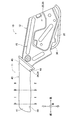
- FIG. 3 is a cross-sectional view showing a configuration of a II cross section in FIG. 2.
- FIG. 3 is a cross-sectional view showing a configuration of a II-II cross section in FIG. 2.
- the parking brake lever device 1 includes a parking brake lever 10 and a sector 80, and is rotatably disposed in a sector 80 fixed to the vehicle.
- the parking brake lever 10 is configured to be able to operate and release the parking brake via a brake cable (not shown) by rotating the parking brake lever 10 by a driver.
- the sector 80 is a substantially flat plate-like member fixed substantially perpendicularly to a vehicle floor (not shown), and supports the parking brake lever 10 so as to be rotatable with respect to the sector 80 via a support pin 85. is doing. That is, the sector 80 functions as a basic configuration in the parking brake lever device 1 according to the present embodiment, and the support pin 85 functions as a rotation center related to the rotation of the parking brake lever 10.
- each direction is defined with reference to the parking brake lever device 1 disposed in the vehicle. That is, the floor side of the vehicle on which the sector 80 is fixed is the downward direction, and the opposite side is the upward direction. Further, as shown in each drawing, the front-rear direction and the left-right direction of the vehicle on which the parking brake lever device 1 is disposed are defined as the front-rear direction and the left-right direction.
- the parking brake lever 10 is a main component member that is rotated by the driver in the parking brake lever device 1, and includes the operation portion 11 and the base end portion 12.
- the operation portion 11 is formed in a substantially cylindrical shape at one end side (front end portion) of the parking brake lever 10 and is gripped by the driver when the parking brake lever 10 is rotated.
- a grip member 40 formed of a hard synthetic resin is fitted to the operation portion 11, and a release knob 60 constituting an operation state maintaining mechanism 50 described later is disposed so as to protrude from the front side end surface of the grip member 40. Has been.
- the base end portion 12 constitutes the other end side (rear end portion) of the parking brake lever 10, and rotates around the support pin 85 with respect to the sector 80 standing on the floor of the vehicle. It is supported movably.
- One end of a brake cable (not shown) is connected to the base end portion 12 via a connecting pin, and the other end side of the brake table is connected to a parking brake.
- the parking brake lever 10 When the parking brake lever 10 is rotated by a driver's operation in a direction that causes the parking brake lever 10 to move upward (hereinafter referred to as an operation direction), the parking brake lever 10 is connected to the base end portion 12 in accordance with the rotation in the operation direction. Pull the brake cable attached to operate the vehicle parking brake. On the other hand, when the parking brake lever 10 is rotated downward (hereinafter referred to as a release direction) so as to approach the vehicle floor by the driver's operation, the parking brake lever 10 is rotated in the release direction. Along with this, the tension of the brake cable connected to the base end portion 12 is released, and the parking brake of the vehicle is released.
- the parking brake lever device 1 according to the present embodiment can apply or release the braking force by the parking brake of the vehicle according to the turning operation of the parking brake lever 10.
- the parking brake lever 10 is composed mainly of a lever body 15 made of a metal plate material, and the parking brake lever 10 is parked under a predetermined condition with a grip member 40 made of hard synthetic resin.
- An operating state maintaining mechanism 50 for maintaining a state in which the brake is operated and a braking force is applied to the vehicle is provided.
- the lever body 15 constituting the parking brake lever 10 will be described with reference to the drawings.
- the lever main body 15 is a main part of the parking brake lever 10 and includes the first half 20 and the second half 30.
- the first half 20 forms a right side portion of the lever body 15 divided in the left-right direction at the center portion in the left-right direction of the lever body 15.
- the second half 30 constitutes the left portion of the lever body 15 divided in the left-right direction.
- the lever body 15 is formed by caulking the support pins 85, the pins 57, and the pins 66 in a state where the first half 20 and the second half 30 are overlapped in the left-right direction.
- the half body 20 and the second half body 30 are integrated, and the operating state maintaining mechanism 50 and the sector 80 are interposed between the first half body 20 and the second half body 30. I am letting.
- the first half 20 is a member constituting the right side portion of the lever main body 15 and is formed by pressing a metal plate material.
- a proximal end component 25 is provided.
- the semi-cylindrical portion 21 is formed by making the front side portion of the first half-divided body 20 into a substantially semi-cylindrical shape by the press working, and constitutes the right-side portion in the operation portion 11 of the lever body 15.
- the base end structure part 25 is formed in the back side part of the 1st half body 20, and comprises the right side part in the base end part 12 of the said lever main body 15.
- the flanges 22 are formed on both side portions in the vertical direction of the semi-cylindrical portion 21 so as to protrude along the longitudinal direction of the semi-cylindrical portion 21 and outward of the semi-cylindrical portion 21.
- the flange 22 is divided into a plurality of portions in the longitudinal direction of the semi-cylindrical portion 21 by a plurality of notches 22A, and the rotation of the grip member 40 is prevented by cooperating with an engagement groove 43 of the grip member 40 described later. Function as.
- a locking claw 23 is cut and raised on the inner surface of the semi-cylindrical portion 21.
- the locking claw 23 protrudes inward of the semicylindrical portion 21, and is locked at a predetermined position inside the cylindrical operation portion 11 by locking the end of the return spring 75 constituting the operating state maintaining mechanism 50. It performs the function of holding.
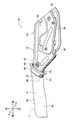
- the locking projection 24 is formed on the lower end edge of the first half 20 at the base portion of the semi-cylindrical portion 21 (between the semi-cylindrical portion 21 and the base end constituting portion 25), and below ( That is, it protrudes toward the release direction side (see FIGS. 1 to 5).
- the locking protrusion 24 functions as a stopper and a rotation stopper of the grip member 40 by cooperating with a locking hole 46 of the grip member 40 described later.
- the second halved body 30 is a member constituting the left side portion of the lever main body 15 and is formed by pressing a metal plate material, and has a semi-cylindrical portion 31 and a base end constituting portion 35. (See FIGS. 4 and 5).
- the semi-cylindrical portion 31 is formed by making the front side portion of the second half-divided body 30 into a substantially semi-cylindrical shape by the above pressing, and constitutes the left side portion of the operation portion 11 of the lever body 15. .
- the operation portion of the lever body 15 having a substantially cylindrical shape is formed by superimposing the half cylinder portion 31 of the second half portion 30 on the half cylinder portion 21 of the first half portion 20. 11 is configured.
- the base end structure part 35 is formed in the back side part of the 2nd half-divided body 30, and comprises the left side part in the base end part 12 of the said lever main body 15.
- FIG. 1 When the first half 20 and the second half 30 are joined, the base end constituting portion 25 and the base end constituting portion 35 face each other with a certain distance therebetween, as shown in FIGS. 1 and 3. Thus, a space in which the constituent members of the operating state maintaining mechanism 50 and the sector 80 can be arranged is formed.
- Flange 32 is formed on both sides of the half cylinder part 31 in the second half body 30 in the vertical direction so as to protrude along the longitudinal direction of the half cylinder part 31 and outward of the half cylinder part 31. ing.
- the flange 32 is divided into a plurality of portions in the longitudinal direction of the semi-cylindrical portion 31 by a plurality of notches 32A, and the rotation of the grip member 40 is prevented by cooperating with an engagement groove 43 of the grip member 40 described later. Function as.
- the flange 32 of the second half 30 is closely attached to the flange 22 of the first half 20. That is, as shown in FIG. 4, both the flange 22 and the flange 32 protrude above and below the cylindrical operation portion 11 by a predetermined dimension.
- the second half 30 is formed with a locking projection 34.
- the locking projection 34 is formed at the lower end edge of the second half 30 at the base portion of the semi-cylindrical portion 31 (between the semi-cylindrical portion 31 and the base end constituting portion 35), and below ( That is, it protrudes toward the release direction side (see FIGS. 1 to 5).
- the locking projections 34 of the second half 30 are in close contact with the locking projections 24 of the first half 20.
- the locking projection 34 is integrated with the locking projection 24 of the first half 20 and cooperates with a locking hole 46 of the grip member 40 described later, whereby the grip member 40 functions as a stopper and a rotation stopper.
- the grip member 40 constituting the parking brake lever 10 will be described in detail with reference to the drawings.
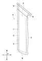
- the grip member 40 is formed of a hard synthetic resin into a cylindrical shape, and is disposed on the outer peripheral portion of the operation portion 11 formed at the front side end portion of the lever body 15. .
- the grip member 40 is a member that is gripped by the driver when the parking brake lever 10 is rotated, and is formed of a hard synthetic resin (for example, polypropylene).
- the grip member 40 is formed in a substantially cylindrical shape, and is attached to the outer peripheral portion of the substantially cylindrical operation portion 11 constituted by the semicylindrical portion 21 and the semicylindrical portion 31.
- the grip member 40 is formed of a hard synthetic resin, but may be formed of a synthetic resin. That is, the grip member 40 can be formed of a soft synthetic resin (for example, polyvinyl chloride).
- the grip member 40 includes a gripping portion 41 that constitutes a main part of the gripping member 40, and an extending portion 45 formed at the end of the gripping portion 41. .
- the grip unit 41 is disposed on the outer periphery of the operation unit 11, and is operated when the parking brake lever 10 is rotated. Gripped by a person's hand.
- the extending portion 45 extends rearward from the entire circumference of the rear end side edge of the gripping portion 41, and has a substantially conical shape formed so that the inner diameter becomes wider toward the rear end side. is doing.
- the extending portion 45 is disposed so as to cover the base portion of the operation portion 11 (that is, between the operation portion 11 and the base end portion 12) when the grip member 40 is attached to the operation portion 11. By covering the base part of the operation part 11 in the lever main body 15, the beauty of the parking brake lever device 1 is enhanced.
- An insertion hole 42 is formed in the grip member 40 formed in a cylindrical shape.
- the insertion hole 42 is formed so as to penetrate in the front-rear direction along the axial direction of the grip member 40, and is configured to allow the operation portion 11 of the lever body 15 to be inserted.
- the inner diameter of the insertion hole 42 is formed in accordance with the outer dimensions of the operation unit 11 constituted by the semi-cylindrical part 21 and the semi-cylindrical part 31 except for the close contact holding part 44 described later. Accordingly, the operation portion 11 of the lever main body 15 can be inserted into the insertion hole 42 of the grip member 40. Since the insertion hole 42 penetrates the grip member 40 in the axial direction, the release knob 60 constituting the operating state maintaining mechanism 50 is disposed so as to protrude from the front end portion of the grip member 40 (FIG. 1 etc.).
- An engagement groove 43 is formed on the inner surface of the insertion hole 42 at the upper and lower sides of the grip member 40 corresponding to the flange 22 in the first half 20 and the flange 32 in the second half 30. It is formed in a groove shape extending in the direction (that is, in the direction of the insertion opening of the operation unit 11).
- the gripping portion 41 of the grip member 40 is formed with a close contact holding portion 44, and the operation portion 11 configured in a cylindrical shape (the semicylindrical portion 21 of the first half-divided body 20 in a state of being overlapped with each other)
- the grip member 40 is held on the outer peripheral portion of the operation portion 11 in close contact with the surface of the semi-cylindrical portion 31) of the second half 30.
- the close contact holding portion 44 is formed on the front end side of the grip member 40, and by making the inner diameter dimension of the insertion hole 42 smaller than the portion other than the close contact holding portion 44. The degree of adhesion to the surface of the operation unit 11 is increased, and the holding power is increased.
- the engagement groove width WA of the engagement groove 43 is equal to the overlapped flange 22 and flange 32.
- the inner surface of the engaging groove 43 is in close contact with the flange 22 and the flange 32.
- the engagement groove width WB of the engagement groove 43 in the II-II cross section other than the close contact holding portion 44 is the overlapped flange 22 and flange 32. It is formed larger than the thickness.
- the inner diameter dimension of the insertion hole 42 (excluding the engagement groove 43 portion) is the main part of the operation portion 11 formed in a cylindrical shape.
- the outer diameter of the portion (that is, excluding the flange 22 and the flange 32 portion) is formed in substantially the same manner.
- the locking hole 46 is formed in the lower part of the extension part 45 so that the extension part 45 may be penetrated (refer FIG. 6, FIG. 7, etc.).
- the engagement hole 46 is positioned below the root portion of the operation portion 11, and the engagement protrusion 24 formed on the lever body 15 and the engagement hole 46 are engaged. It is inserted by the stop protrusion 34 (see FIGS. 1 and 8). Therefore, according to the parking brake lever device 1, the locking hole 46 of the grip member 40 is locked by the locking protrusion 24 and the locking protrusion 34 of the lever main body 15, and the grip member 40 is prevented from being detached from the operation portion 11. Functions as a rotation stopper.
- the operating state maintaining mechanism 50 is a mechanism for maintaining the parking brake operating state with the rotation of the parking brake lever 10 or for releasing the operating state of the parking brake.
- a release rod 51, a release knob 60, a pole 65, a ratchet 70, and a return spring 75 are examples of the operating state maintaining mechanism 50.
- the release rod 51 is a rod-like member disposed inside the operation portion 11 formed in a cylindrical shape so as to be slidable along the axial direction of the operation portion 11, and includes a mounting protrusion 52 and a spring holding portion 53. And a long hole 54 and a pole connecting portion 56.
- the attachment protrusion 52 is formed on one end side of the release rod 51 and is disposed on the front end side of the operation unit 11.
- the mounting protrusion 52 is formed by bending the front end portion of the release rod 51 in the right direction orthogonal to the sliding direction. By fitting with the mounting hole of the release knob 60, the release knob 60 is released. It is held at the front end of the rod 51.
- a spring holding portion 53 is formed on the rear side of the mounting projection 52, and the return spring 75 is brought into contact with the rear end portion of the return spring 75 as shown in FIGS. Hold on the back.
- an elongated hole 54 is formed in the rear portion of the release rod 51 from the spring holding portion 53.
- the long hole 54 is formed so that its long diameter is along the axial direction of the release rod 51, and is inserted through a pin 57 that caulks and joins the first half 20 and the second half 30.
- the release rod 51 can slide in the front-rear direction along the axial direction of the operation unit 11 by the cooperation of the long hole 54 and the pin 57.
- a pole connecting portion 56 is formed at the rear end portion of the release rod 51 and is connected to a pole 65 constituting the operating state maintaining mechanism 50. Thereby, inside the parking brake lever 10, the displacement due to the sliding movement of the release rod 51 acts on the pole 65, and the posture of the pole 65 can be changed.
- the release knob 60 is attached to the front end portion of the release rod 51 by an attachment projection 52 of the release rod 51, and is formed to have an inclined end surface 61 and a hollow portion 62 by synthetic resin.
- the release knob 60 is disposed so as to protrude from the front end face of the parking brake lever 10, and the release rod 51 is slid by moving the release knob 60.
- An inclined end surface 61 is formed on the front end surface of the release knob 60, and the lower end is inclined so as to be forward. By inclining the inclined end surface 61 in this way, the operability related to the pushing operation of the release knob 60 is enhanced and the aesthetic appearance of the parking brake lever device 1 is enhanced.
- the hollow portion 62 is a gap formed in a predetermined shape inside the release knob 60, and suppresses the occurrence of sink marks and voids when the release knob 60 is molded with synthetic resin.
- the pole 65 is disposed inside the base end portion 12 of the lever main body 15 and is disposed so as to be swingable about a pin 66 as an axis.
- the pin 66 pivotally supports the pole 65 so as to be able to swing, and the base end component 25 of the first half 20 and the base end component 35 of the second half 30 are caulked and joined.
- the pole 65 is connected to the pole connecting portion 56 formed at the rear end portion of the release rod 51, so that the pin 66 swings around the pin 66 as the release rod 51 slides. , Abuts on and separates from the tooth portion 71 of the ratchet 70.
- the ratchet 70 is fixed to the sector 80 and has a plurality of teeth 71 arranged in an arc shape with the support pin 85 as the center.
- the teeth 71 of the ratchet 70 are formed so that claws formed at one end of the pole 65 mesh with each other as the pole 65 swings.
- the pawl 65 is engaged with the teeth 71 of the ratchet 70, so that the rotation of the parking brake lever 10 is restricted.
- the meshing of the ratchet 70 with the tooth portion 71 is released when the release rod 51 is slid rearward by the pushing operation of the release knob 60, and the pole 65 swings with the movement of the pole connecting portion 56.
- the return spring 75 is constituted by a compression coil spring, and is disposed between the locking claw 23 of the lever body 15 and the release knob 60.
- the return spring 75 urges the release rod 51 and the release knob 60 toward the front side of the parking brake lever 10 so that the release knob 60 protrudes from the front end portion of the parking brake lever 10. Therefore, the urging force of the return spring 75 urges the release rod 51 and the release knob 60 toward the front side of the parking brake lever 10 and urges the pawl 65 so that the pawl 65 meshes with the tooth portion 71 of the ratchet 70. .
- the driver rotates the parking brake lever 10 in the operating direction in the parking brake lever device 1. Specifically, the driver holds the grip member 40 of the parking brake lever 10 and pulls it upward. As a result, the parking brake lever 10 rotates about the support pin 85 upward (that is, counterclockwise in FIG. 1).
- the pole 65 swings around the pin 66 against the urging force of the return spring 75 and sequentially passes over the teeth 71 of the ratchet 70. Thereafter, when the rotation of the parking brake lever 10 in the operating direction is stopped, the pawl 65 keeps meshing with the tooth portion 71 of the ratchet 70 and restricts the rotation of the parking brake lever 10 in the release direction. . By restricting the rotation of the parking brake lever 10, the state of the brake cable is also maintained, and the operation state of the parking brake is maintained.
- the release knob 60 When the release knob 60 is pushed while rotating the parking brake lever 10 in the operating direction, the release rod 51 slides backward to the parking brake lever 10 against the urging force of the return spring 75. To do. As a result, the pole 65 swings around the pin 66 and the meshing between the pawl of the pole 65 and the tooth portion 71 of the ratchet 70 is released. By entering this state, the parking brake lever 10 can be rotated in the release direction.
- the brake cable connected to the base end portion 12 of the parking brake lever 10 is loosened, so that the operation of the parking brake connected to the other end of the brake cable is activated.
- the braking force for the vehicle is removed.
- the lever body 15 includes the first half 20 and the second half 30 such that the flange 22 of the semicylindrical portion 21 and the flange 32 of the semicylindrical portion 31 are overlapped.
- the pin 57, the pin 66 and the support pin 85 are joined by caulking.
- the locking projections 24 of the first half 20 and the locking projections 34 of the second half 30 are also substantially integrated in an overlapped state.
- Each component (for example, the release rod 51 and the release knob 60) of the operating state maintaining mechanism 50 is disposed at a predetermined position between the first half 20 and the second half 30. In this state, the first half 20 and the second half 30 are joined to each other to be disposed inside the lever main body 15.
- the grip member 40 When the grip member 40 is attached to the operation portion 11 of the lever main body 15, first, the first half 20 and the second half are inserted into the insertion hole 42 of the grip member 40 formed of hard synthetic resin.
- the operation part 11 of the lever main body 15 constituted by joining 30 is press-fitted.
- the flange 22 and the flange 32 formed on the top and bottom of the operation unit 11 are fitted to the engagement grooves 43 formed on the top and bottom of the insertion hole 42, and the base is viewed from the front end side of the operation unit 11. Press-fit toward the end 12.
- the inner diameter dimension of the insertion hole 42 in the grip member 40 is formed to be substantially equal to the outer diameter dimension of the main part of the operation portion 11 having a cylindrical shape. There is almost no change between the close contact holding portion 44 formed on the front end side and other portions. Therefore, the magnitude of the friction generated between the operation unit 11 and the main part does not vary greatly depending on whether or not the contact holding unit 44 is provided.
- the engagement groove width WA of the engagement groove 43 in the close contact holding portion 44 is formed with a dimension corresponding to the thickness of the flange 22 and the flange 32.
- the engagement groove width WB of the engagement groove 43 on the rear end side of the grip member 40 is slightly wider than the thicknesses of the flange 22 and the flange 32 (see FIG. 10). Therefore, even when the close contact holding portion 44 is formed on the grip member 40, the press-fitting load when the grip member 40 is press-fitted into the operation portion 11 is caused by friction between the close contact holding portion 44 and the engagement groove 43. It only increases.
- the grip member 40 with respect to the operation portion 11 is kept while keeping the increase in press-fitting load to a minimum. It is possible to enhance the adhesion maintaining effect.
- the parking brake lever device 1 performs an operation of locking the locking protrusions 24 and the locking protrusions 34 of the lever main body 15 with respect to the locking holes 46 of the extending portion 45. Is called.
- a gap 47 is formed between the upper surface of the lever body 15 and the inner surface of the extension portion 45. .
- the gap 47 is formed in a size corresponding to the protruding amount of the locking protrusion 24 and the locking protrusion 34 formed on the lower side of the lever main body 15.
- the entire extending portion 45 of the grip member 40 is bent downward using the gap 47 formed on the upper side of the lever main body 15, so that the relative to the lever main body 15. Can be displaced.
- the entire extension portion 45 of the grip member 40 is bent downward by using the gap 47, so that the position of the lever body 15 is lowered.
- the gripping member 40 can be locked to the operation portion 11 of the lever main body 15 by inserting the locking protrusion 24 and the locking protrusion 34 to be inserted into the locking hole 46 of the extending portion 45.
- the grip member 40 is formed of a hard synthetic resin typified by polypropylene or the like, but may be formed of a soft synthetic resin typified by polyvinyl chloride or the like.
- the grip member 40 is formed of a soft synthetic resin, it can be more easily elastically deformed than when it is formed of a hard synthetic resin. It is possible to attach a grip member 40 formed of a soft synthetic resin.
- the parking brake lever device 1 has the lever body 15 constituting the parking brake lever 10 and the grip member 40 made of hard synthetic resin, and the lever body 15 And the parking brake is operated by rotating in a predetermined operating direction.
- a locking projection 24 and a locking projection 34 are formed so as to protrude downward from the operation portion 11 on the base end portion 12 side, and are made of a synthetic resin grip member.
- a locking hole 46 is formed in the extended portion 45 of 40 (see FIGS. 1 and 7). According to the parking brake lever device 1, when the grip member 40 is attached to the lever body 15, the locking hole 46 of the grip member 40 can be locked by the locking protrusion 34 of the lever body 15. In the base end portion 12 side, it is possible to prevent the grip member 40 from coming off and from rotating against the lever main body 15.
- a close contact holding portion 44 is formed in a portion corresponding to the grip portion 41 and is in close contact with the surface of the operation portion 11 of the lever main body 15. According to the parking brake lever device 1, the close contact holding portion 44 can function as a retaining member for the grip body 40 with respect to the lever main body 15 and the grip member for the lever main body 15 on the distal end side of the lever main body 15. 40 rattles can be suppressed.
- the locking protrusion 24, the locking protrusion 34, the locking hole 46, and the close contact holding portion 44 are formed, so that the grip member 40 made of synthetic resin is attached to the lever. Even when attached to the operation unit 11 of the main body 15, it is possible to realize the retaining and rotation prevention with respect to the lever main body 15 at both ends of the grip member 40.
- the extending portion 45 of the grip member 40 extends so that the inner diameter is greatly expanded toward the base end portion 12, and on the upper side of the lever main body 15, A gap 47 is formed between the inner surface and the surface of the lever body 15 (see FIG. 8).
- the extension portion 45 of the grip member 40 can be displaced downward relative to the lever main body 15 by using the gap 47 located on the upper side of the lever main body 15, and this variation is utilized.
- the locking projection 24 and the locking projection 34 of the lever main body 15 can be inserted into the locking hole 46 of the grip member 40. That is, according to the parking brake lever device 1, even the grip member 40 formed of hard synthetic resin can be attached to the operation unit 11 of the lever body 15, and the grip member 40 can be prevented from coming off and rotating. It can be realized.
- the lever main body 15 is configured by overlapping and joining the first half 20 and the second half 30, and the first half 20 includes a half cylindrical portion 21 and a flange 22.
- the second half 30 has a semi-cylindrical portion 31 and a flange 32.
- An engagement groove 43 is formed on the inner wall surface of the insertion hole 42 of the grip member 40.
- the engagement groove width WA of the engagement groove 43 in the close contact holding portion 44 is equal to the engagement in the other portion of the grip portion 41.
- the groove 43 is formed to be smaller than the engagement groove width WB, and the flange 22 and the flange 32 are tightly held by the inner wall surface of the engagement groove 43.
- the resistance that acts when the operating portion 11 of the lever main body 15 is press-fitted into the insertion hole 42 of the grip member 40 is a friction force generated between the insertion hole 42 of the grip member 40 and the lever main body 15. to cause.
- the lever main body 15 is configured to join the first half 20 and the second half 30, but is not limited to this mode.
- the structure which forms a lever main body by performing press work etc. with respect to one metal plate material may be sufficient.
- various modes are possible, such as the whole or part of the lever body 15 being made of a synthetic resin material.
- the engagement groove width WA of the engagement groove 43 is formed to be smaller than other portions, and the flange 22 and the flange 32 of the operation portion 11 are formed.
- the inner diameter dimension of the insertion hole 42 in the close contact holding portion 44 may be formed smaller than that of other portions so as to be in close contact with the surface of the cylindrical operation portion 11.
- the depth of the engagement groove 43 related to the close contact holding portion 44 may be formed to be shallower than the depth of the engagement groove 43 related to other portions, and may be brought into close contact with the flange 22 and the flange 32.
- the width and depth dimensions of the engagement groove 43 related to the close contact holding portion 44 are formed smaller than the width and depth dimensions of the engagement groove 43 related to other portions, and the close contact with the flange 22 and the flange 32 is achieved. It is also possible to adopt a configuration to make it.
- the 1st half body 20 and the 2nd half body 30 which comprise the lever main body 15 were the structures which have the semicylindrical part 21 and the semicylindrical part 31, respectively, it is not limited to this aspect. .
- the operation unit 11 that is at least the tip of the lever body 15 is configured separately, various configurations can be employed.
- the latching protrusion in the lever main body 15 is configured by overlapping and joining the latching protrusion 24 of the first half 20 and the latching protrusion 34 of the second half 30. It is not limited to the embodiment, and it is sufficient if the lever main body 15 has a locking projection. For example, it is also possible to form a locking projection only on one of the first half 20 and the second half 30 and to join both of them together.
- the lever main body 15 is configured by joining the first half 20 and the second half 30 by caulking the pin 57, the pin 66, and the support pin 85. It is not limited to an aspect, The structure joined integrally by connection means, such as welding and a volt
Landscapes
- Engineering & Computer Science (AREA)
- Physics & Mathematics (AREA)
- General Physics & Mathematics (AREA)
- Automation & Control Theory (AREA)
- Transportation (AREA)
- Mechanical Engineering (AREA)
- Braking Elements And Transmission Devices (AREA)
- Mechanical Control Devices (AREA)
Abstract
La présente invention concerne un dispositif de levier de frein de stationnement, actionné de manière à actionner ou libérer un frein de stationnement et apte à retenir et à arrêter la rotation d'un corps principal de levier, indépendamment du fait qu'un élément de préhension comprenne une résine synthétique molle ou une résine synthétique dure. Le dispositif (1) de levier de frein de stationnement comprend un levier (10) de frein de stationnement et un secteur (80) et il est conçu de sorte que le frein de stationnement puisse être actionné et libéré par rotation du levier (10) de frein de stationnement autour du secteur (80). Un élément de préhension (40) en résine synthétique dure est fixé à une section (11) d'actionnement cylindrique, dans le corps principal (15) de levier du levier (10) de frein de stationnement. Une section de maintien (44) à forte adhérence est formée dans un trou d'insertion (42) de l'élément de préhension (40) et adhère fortement à la surface de la section (11) d'actionnement. Un trou de verrouillage (46) est formé dans une section d'extension (45) de l'élément de préhension (40) et une saillie de verrouillage, formée dans le corps principal (15) de levier, est insérée en son sein.
Applications Claiming Priority (2)
| Application Number | Priority Date | Filing Date | Title |
|---|---|---|---|
| JP2014-151448 | 2014-07-25 | ||
| JP2014151448A JP6063421B2 (ja) | 2014-07-25 | 2014-07-25 | パーキングブレーキレバー装置 |
Publications (1)
| Publication Number | Publication Date |
|---|---|
| WO2016013246A1 true WO2016013246A1 (fr) | 2016-01-28 |
Family
ID=55162785
Family Applications (1)
| Application Number | Title | Priority Date | Filing Date |
|---|---|---|---|
| PCT/JP2015/056922 Ceased WO2016013246A1 (fr) | 2014-07-25 | 2015-03-10 | Dispositif de levier de frein de stationnement |
Country Status (2)
| Country | Link |
|---|---|
| JP (1) | JP6063421B2 (fr) |
| WO (1) | WO2016013246A1 (fr) |
Citations (4)
| Publication number | Priority date | Publication date | Assignee | Title |
|---|---|---|---|---|
| JPS6051170U (ja) * | 1983-09-19 | 1985-04-10 | 日産ディーゼル工業株式会社 | 駐車ブレ−キレバ− |
| JPS6171561U (fr) * | 1984-10-17 | 1986-05-15 | ||
| JPH03227760A (ja) * | 1989-12-15 | 1991-10-08 | Hosei Brake Kogyo Kk | パーキングブレーキ用操作レバー |
| JP2002079924A (ja) * | 2000-07-20 | 2002-03-19 | Breed Automot Technol Inc | 駐車ブレーキ用カバー |
Family Cites Families (1)
| Publication number | Priority date | Publication date | Assignee | Title |
|---|---|---|---|---|
| JP4121784B2 (ja) * | 2002-06-10 | 2008-07-23 | 豊田鉄工株式会社 | 操作レバーのグリップ取付構造 |
-
2014
- 2014-07-25 JP JP2014151448A patent/JP6063421B2/ja not_active Expired - Fee Related
-
2015
- 2015-03-10 WO PCT/JP2015/056922 patent/WO2016013246A1/fr not_active Ceased
Patent Citations (4)
| Publication number | Priority date | Publication date | Assignee | Title |
|---|---|---|---|---|
| JPS6051170U (ja) * | 1983-09-19 | 1985-04-10 | 日産ディーゼル工業株式会社 | 駐車ブレ−キレバ− |
| JPS6171561U (fr) * | 1984-10-17 | 1986-05-15 | ||
| JPH03227760A (ja) * | 1989-12-15 | 1991-10-08 | Hosei Brake Kogyo Kk | パーキングブレーキ用操作レバー |
| JP2002079924A (ja) * | 2000-07-20 | 2002-03-19 | Breed Automot Technol Inc | 駐車ブレーキ用カバー |
Also Published As
| Publication number | Publication date |
|---|---|
| JP6063421B2 (ja) | 2017-01-18 |
| JP2016028907A (ja) | 2016-03-03 |
Similar Documents
| Publication | Publication Date | Title |
|---|---|---|
| JP5453699B2 (ja) | フロアマットをカーペットに固定する固定装置 | |
| US8621956B2 (en) | Seat actuator | |
| JP5932609B2 (ja) | 車両用ドアのアウトハンドル装置 | |
| CN103821921A (zh) | 变速杆用把手的按钮结构 | |
| WO2013161482A1 (fr) | Poignée pour véhicule | |
| JP2014061781A (ja) | 乗物用ラッチ装置 | |
| JP6236376B2 (ja) | パーキングブレーキ操作装置 | |
| JP6063421B2 (ja) | パーキングブレーキレバー装置 | |
| JP2016002909A (ja) | 足踏み式パーキングブレーキ装置 | |
| JP6140113B2 (ja) | パーキングブレーキレバー装置 | |
| CN106103215B (zh) | 用于驻车制动器的致动装置 | |
| CN103596820B (zh) | 驻车制动器操作装置 | |
| JP3104465U (ja) | ロック手段解放操作用の2つの引手を備えたジップファスナ用スライダ | |
| JP2007161183A (ja) | パーキングブレーキ装置 | |
| CN101164815B (zh) | 驻车制动装置的把手构造 | |
| JP4936361B2 (ja) | 車両用シート等のロック付き操作装置 | |
| JP4121784B2 (ja) | 操作レバーのグリップ取付構造 | |
| JP2017052495A (ja) | パーキングブレーキレバー装置 | |
| JP4870465B2 (ja) | 車両用シートバックのロック構造 | |
| KR101578072B1 (ko) | 헤드레스트 이동장치 | |
| JPS625701Y2 (fr) | ||
| JP5913769B2 (ja) | 車両用グリップ構造 | |
| JP6728266B2 (ja) | パーキングブレーキ装置 | |
| KR20130072020A (ko) | 차량용 케이블 연결 구조 | |
| JP5969807B2 (ja) | 車両用ハンドルおよび車両用ハンドルの製造方法 |
Legal Events
| Date | Code | Title | Description |
|---|---|---|---|
| 121 | Ep: the epo has been informed by wipo that ep was designated in this application |
Ref document number: 15824448 Country of ref document: EP Kind code of ref document: A1 |
|
| NENP | Non-entry into the national phase |
Ref country code: DE |
|
| 122 | Ep: pct application non-entry in european phase |
Ref document number: 15824448 Country of ref document: EP Kind code of ref document: A1 |