WO2016013301A1 - Pompe à carburant à haute pression - Google Patents
Pompe à carburant à haute pression Download PDFInfo
- Publication number
- WO2016013301A1 WO2016013301A1 PCT/JP2015/065968 JP2015065968W WO2016013301A1 WO 2016013301 A1 WO2016013301 A1 WO 2016013301A1 JP 2015065968 W JP2015065968 W JP 2015065968W WO 2016013301 A1 WO2016013301 A1 WO 2016013301A1
- Authority
- WO
- WIPO (PCT)
- Prior art keywords
- valve body
- curvature
- radius
- curvature radius
- seat
- Prior art date
- Legal status (The legal status is an assumption and is not a legal conclusion. Google has not performed a legal analysis and makes no representation as to the accuracy of the status listed.)
- Ceased
Links
Images



Classifications
-
- F—MECHANICAL ENGINEERING; LIGHTING; HEATING; WEAPONS; BLASTING
- F02—COMBUSTION ENGINES; HOT-GAS OR COMBUSTION-PRODUCT ENGINE PLANTS
- F02M—SUPPLYING COMBUSTION ENGINES IN GENERAL WITH COMBUSTIBLE MIXTURES OR CONSTITUENTS THEREOF
- F02M59/00—Pumps specially adapted for fuel-injection and not provided for in groups F02M39/00 -F02M57/00, e.g. rotary cylinder-block type of pumps
- F02M59/44—Details, components parts, or accessories not provided for in, or of interest apart from, the apparatus of groups F02M59/02 - F02M59/42; Pumps having transducers, e.g. to measure displacement of pump rack or piston
-
- F—MECHANICAL ENGINEERING; LIGHTING; HEATING; WEAPONS; BLASTING
- F02—COMBUSTION ENGINES; HOT-GAS OR COMBUSTION-PRODUCT ENGINE PLANTS
- F02M—SUPPLYING COMBUSTION ENGINES IN GENERAL WITH COMBUSTIBLE MIXTURES OR CONSTITUENTS THEREOF
- F02M59/00—Pumps specially adapted for fuel-injection and not provided for in groups F02M39/00 -F02M57/00, e.g. rotary cylinder-block type of pumps
- F02M59/44—Details, components parts, or accessories not provided for in, or of interest apart from, the apparatus of groups F02M59/02 - F02M59/42; Pumps having transducers, e.g. to measure displacement of pump rack or piston
- F02M59/46—Valves
Definitions
- the present invention relates to a relief valve that relieves high-pressure fuel from a high-pressure side to a low-pressure side in a high-pressure fuel pump, and a high-pressure fuel pump including the relief valve.
- the high-pressure fuel pump that supplies the pressurized fuel to the internal combustion engine can be used in a fuel supply system based on a direct injection operation in which the fuel is directly injected into the combustion chamber of the internal combustion engine by an injector.
- a relief valve is provided in the fuel supply system in order to prevent the fuel pressure from exceeding a permissible value when the high-pressure fuel pump fails or the like, and damage to the piping and injectors.
- the relief valve is connected to the high-pressure side fuel passage downstream of the discharge valve that discharges fuel pressurized in the pressurizing chamber of the high-pressure pump, and the low-pressure side fuel passage. When the pressure in the high-pressure side fuel passage becomes higher than a predetermined pressure, the relief valve opens and has a function of reducing the fuel pressure in the high-pressure side fuel passage (see, for example, Patent Document 1).
- the conventional technology has the following problems.
- the relief valve of the high-pressure fuel pump has a function to suppress the occurrence of abnormal pressure where the discharge pressure becomes higher than the allowable value. Therefore, when the discharge pressure becomes higher than the set pressure, the valve body of the relief valve opens, and the high pressure can be lowered by fuel flowing from the relief valve to the low pressure side. When the discharge pressure is less than the allowable value, the valve body needs to be seated on the seat portion to completely seal the fuel. When the valve body of the relief valve opens and the fuel flows from the high pressure side to the low pressure side, the fuel flows at high speed through the flow path formed by the seat member and the valve body.
- peeling can be suppressed by taking a large radius of curvature at the edge where high-speed fuel passes.
- a large radius of curvature at the edge portion narrows the passage on the high pressure side of the relief valve. If the passage on the high-pressure side becomes narrow, the flow rate characteristics of the relief valve will deteriorate, and even if the relief valve opens, it will not be possible to flow a sufficient flow rate, so the effect of reducing the pressure will not be sufficiently obtained There was a case.
- the present invention has been made based on the above circumstances, and an object of the present invention is to provide a high-pressure fuel pump that achieves both suppression of cavitation generation and improvement of flow characteristics.
- the above object can be achieved, for example, by setting the curvature of the valve body and the seat part to appropriate values.
- FIG. 1 shows the overall configuration of a system for implementing the present invention.
- a portion surrounded by a broken line in FIG. 1 shows a pump housing 1 of a high-pressure fuel supply pump, and a mechanism and parts shown in the broken line are integrally incorporated therein.
- the fuel in the fuel tank 20 is pumped up by the feed pump 21 and sent to the fuel inlet 10 a of the pump housing 1 through the suction pipe 28.
- the fuel that has passed through the fuel intake port 10a reaches the intake port 30a of the electromagnetic intake valve mechanism 30 that constitutes the variable capacity mechanism via the pressure pulsation reducing mechanism 9 and the intake passage 10c.
- the electromagnetic suction valve mechanism 30 includes an electromagnetic coil 30b, and in a state where the electromagnetic coil 30b is energized, the electromagnetic plunger 30c compresses the spring 33 and moves to the right in FIG. Maintained. At this time, the suction valve body 31 attached to the tip of the electromagnetic plunger 30c opens the suction port 32 leading to the pressurizing chamber 11 of the high-pressure fuel supply pump.
- the electromagnetic coil 30 b is not energized and there is no fluid differential pressure between the suction passage 10 c (suction port 30 a) and the pressurizing chamber 11, the suction valve body 31 is moved by the biasing force of the spring 33.
- the suction port 32 is urged in the valve closing direction (leftward in FIG. 1) to be closed, and this state is maintained.
- the suction valve body 31 is moved leftward in FIG. 1 by the urging force of the spring 33 that is constantly acting on the suction valve body 31 to close the suction port 32.
- the suction port 32 is closed, the fuel pressure in the pressurizing chamber 11 rises with the rise of the plunger 2 from this time.
- the fuel pressure in the pressurizing chamber 11 exceeds a pressure larger than the fuel pressure in the discharge port 13 by a predetermined value, the fuel remaining in the pressurizing chamber 11 is discharged via the discharge valve mechanism 8. High pressure discharge is performed and supplied to the common rail 23. This process is called a discharge process.
- the compression process of the plunger 2 includes a return process and a discharge process.
- the pressure pulsation is generated in the suction passage due to the fuel returned to the suction passage 10c, but this pressure pulsation only slightly flows backward from the suction port 10a to the suction pipe 28, and the fuel is returned. Most of the energy is absorbed by the pressure pulsation reducing mechanism 9.
- the timing of releasing the energization of the electromagnetic coil 30c of the electromagnetic intake valve mechanism 30 the amount of high-pressure fuel discharged can be controlled. If the timing of releasing the energization to the electromagnetic coil 30b is advanced, the ratio of the return process in the compression process is reduced and the ratio of the discharge process is increased.
- the amount of fuel returned to the suction passage 10c is reduced and the amount of fuel discharged at high pressure is increased.
- the timing of releasing the energization is delayed, the ratio of the return process in the compression process is increased and the ratio of the discharge process is decreased. That is, more fuel is returned to the suction passage 10c and less fuel is discharged at high pressure.
- the timing of releasing the energization is controlled by a command from the ECU.
- the ECU controls the timing of releasing the energization of the electromagnetic coil, whereby the amount of fuel discharged at a high pressure can be made the amount required by the internal combustion engine.
- a discharge valve mechanism 8 is provided on the outlet side of the pressurizing chamber 11 between the discharge port (discharge side pipe connection portion) 13.
- the discharge valve mechanism 8 includes a sheet member 8a, a discharge valve 8b, a discharge valve spring 8c, and a holding member (discharge valve stopper) 8d.
- the discharge valve 8b In a state where there is no fuel differential pressure between the pressurizing chamber 11 and the discharge port 13, the discharge valve 8b is pressed against the seat member 8a by the urging force of the discharge valve spring 8c and is in a closed state.
- the discharge valve 8b After the discharge valve 8b is opened, the operation is restricted when it comes into contact with the holding member 8d. Therefore, the stroke of the discharge valve 8b is appropriately determined by the holding member 8d. If the stroke is too large, the fuel discharged to the fuel discharge port 13 flows back into the pressurizing chamber 11 again due to the delay in closing the discharge valve 8b, so that the efficiency of the high-pressure pump decreases. . Further, when the discharge valve 8b repeats opening and closing movements, the holding member 8d guides the discharge valve so as to move only in the stroke direction. By configuring as described above, the discharge valve mechanism 8 becomes a check valve that restricts the flow direction of fuel.
- the fuel introduced to the fuel suction port 10a is pressurized to a required amount by the reciprocating motion of the plunger 2 in the pressurizing chamber 11 of the pump body 1, and the fuel discharge port 13 passes through the discharge valve mechanism 8.
- the common rail 23 which is a high-pressure pipe.
- the common rail 23 is provided with an injector 24 and a pressure sensor 26.
- the injectors 24 are mounted in accordance with the number of cylinders of the internal combustion engine, and the fuel is injected into the cylinders by operating the on-off valve according to the control signal of the ECU 27.
- the pump housing 1 is provided with a relief passage 300 that connects the discharge passage 12 and the suction passage 10c.
- the relief passage 300 restricts the flow of fuel in only one direction from the discharge passage 12 to the suction passage 10c.
- a valve 200 is provided.
- the fuel flow in the relief passage 300 may flow from the discharge passage 12 into the pressurizing chamber 11.
- FIG. 3 shows a cross section of the relief valve according to the first embodiment of the present invention.
- the relief valve 200 includes a valve body 201, an elastic member 203 that biases the valve body, a seat member 204 that engages with the valve body to seal fuel, a housing 205, a high-pressure chamber 206 on the upstream side of the valve body, and a downstream side of the valve body.
- the low-pressure chamber 207 is configured.
- the valve body 201 is urged against the sheet portion 204 by the elastic member 203 against the high pressure guided from the discharge flow path 12.
- a position where the valve body 201 and the sheet member 204 are in contact with each other is defined as a seat position 202.
- the seat position 202 In the cross section in the vicinity of the seat position 202, when the valve body 201 and the sheet member 204 are parallel straight lines, the seat position 202 has a width, and the valve body 201 and the sheet member 204 are in surface contact.
- the valve body 201 In the cross section in the vicinity of the seat position 202, when the valve body 201 is a curve and the seat member 204 is a straight line, they contact at one point from a geometrical point of view.
- the seat position 202 has a certain width, and even in this case, it can be said that the valve body 201 and the seat member 204 are in surface contact.
- a high-pressure passage 207 leading to the high-pressure chamber 206 is provided on the upstream side of the seat position 202, and the diameter of the high-pressure passage 207 is defined as a high-pressure passage diameter 208. If the high-pressure passage diameter 208 is small, the high-pressure passage 207 becomes narrow, and it becomes difficult for the fuel to flow when the relief valve is opened. In order to allow sufficient fuel to flow when the relief valve is opened, that is, to obtain good flow characteristics, it is desirable to increase the high-pressure passage diameter 208.
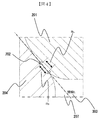
- FIG. 4 is an enlarged view of the shape in the vicinity of the sheet position 202 in the cross-sectional view of FIG.
- the valve body 201 and the seat member 204 are in contact with each other at the seat position 202, and have a common tangent L303 on the cross section shown in FIG. Further, the valve body 201 is provided with a curvature radius Rv in the vicinity of the seat position 202, and similarly, the seat member 204 is provided with a curvature radius Rs in the vicinity of the seat position 202.
- the curvature radius Rv and the curvature radius Rs are in contact with each other at the seat position 202, and not only the vicinity of the seat position 202 but also the same curvature radius may continue upstream and downstream of the seat position 202.
- the curvature radius Rs and the curvature radius Rv can be set to arbitrary values, and the curvature radius may be infinite, that is, arranged as a straight line.
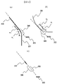
- FIG. 5A shows a schematic view of the shape of the sheet member 204
- FIG. 5B shows a schematic view of the shape of the valve body 201.
- the curvature radius R2 smaller than the curvature radius Rs of the sheet
- a section obtained by projecting the section having the radius of curvature R2 perpendicularly to the tangent L303 is defined as a projection section 306.
- the valve body 201 is provided with a curvature radius R1 smaller than the curvature radius Rv in the vicinity of the seat position 202 at least at one location upstream of the seat position 202.
- a section obtained by vertically projecting the section having the curvature radius R1 onto the tangent line L303 is defined as a projection section 305.
- FIG. 5C schematically shows the positional relationship between the projection sections.
- the curvature radius R1 and the curvature radius R2 are arranged upstream of the sheet position 202 so that the projection section 306 and the projection section 305 overlap at least partially on the tangent L303.
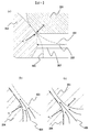
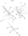
- FIG. 6 (a) shows a comparison between the prior art and the present invention.
- the cross-sectional shape of the sheet member in the prior art is indicated by 402, and the cross-sectional shape of the valve body is indicated by 401.
- the sheet member 204 is provided with a radius of curvature R2 from Rv to the high-pressure passage 207, so that the high-pressure passage diameter 208 is larger than that of the conventional sheet member shape 402. Can do.
- FIG. 6B schematically shows the fuel flow direction 404 when the valve body 201 is not provided with R1.
- R1 is not provided on the valve body side
- the flow of fuel 404 is uneven between the flow along the seat member and the flow along the valve body, and when high-speed fuel passes, the flow direction of the fuel changes abruptly. End up.
- FIG. 6C schematically shows the fuel flow direction 405 when the valve body 201 is provided with R1.
- the curvature radius R1 and the curvature radius R2 are set to be close values, and the projection section 306 and the projection section 305 are arranged so as to largely overlap, so that the flow along the valve body and the flow along the seat member are It becomes more even and prevents the flow direction from changing suddenly. Therefore, separation of fluid and vortex are less likely to occur, and a great effect can be obtained by suppressing the occurrence of cavitation.
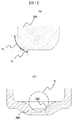
- FIG. 7 shows a cross-sectional shape of the sheet member 204 in the second embodiment of the present invention.
- a curvature radius Rs is provided in the vicinity of the seat position 202 in contact with the valve body 201.
- the radius of curvature Rs is infinite, that is, arranged as a straight line.
- an edge 501 is formed upstream of the polished surface. If the curvature radius R2 is arranged further upstream of the edge 501, the flow direction of the fuel does not change suddenly even when the fuel passes through the vicinity of the edge 501, and the occurrence of cavitation can be suppressed and erosion can be avoided. it can.
- FIG. 8A shows a cross-sectional shape of the valve body 201 according to the second embodiment of the present invention.
- a radius of curvature R0 is provided in the vicinity of the sheet position 202 in contact with the sheet member 201.
- the definition of the radius of curvature R0 is shown in FIG.
- the curvature radius R ⁇ b> 0 is a radius of a sphere that is in contact with the same position as the seat position 202 in contact with the valve body 201 in the seat member 204.
- the radius of curvature of the ball when the ball is used as the valve body in the prior art is R0.
- the curvature radius R0 is set as the curvature radius in the vicinity of the seat position 202, and a curvature radius R1 smaller than the curvature radius R0 is provided on the upstream side of the curvature radius R0.
- FIG. 9 shows the positional relationship between the projection section 305 and the projection section 306 on the tangent line L303 in the second embodiment.
- a curvature radius R2 is provided upstream of the sheet position 202, and a section obtained by projecting the section of the curvature radius R2 perpendicularly to the tangent L303 is defined as a projection section 306.
- the curvature radius R0 is set as the curvature radius in the vicinity of the seat position 202, and a curvature radius R1 smaller than the curvature radius R0 is provided on the upstream side of the curvature radius R0.
- 9C schematically shows the positional relationship between the projection sections.
- the curvature radius R1 and the curvature radius R2 are arranged upstream of the sheet position 202 so that the projection section 306 and the projection section 305 overlap at least partially on the tangent L303.
- the valve body 201 and the sheet member 204 come into contact with the spherical surface and the conical surface only in the vicinity of the seat position 202. Therefore, as long as the valve body 201 is in contact with the sheet member 204 within the range of the curvature radius R0, even when the valve body 201 is tilted, the sheet property can be maintained without generating a gap. If the section of the radius of curvature R0 is provided based on the maximum inclination angle allowed for the structure of the valve body 201, the sheet property can be maintained even when the valve body 201 is inclined most greatly.
- a curvature radius R1 smaller than the curvature radius R0 is provided upstream of the curvature radius R0, and the curvature radius R1 and the curvature radius R2 are arranged so that the projection section 306 and the projection section 305 at least partially overlap on the tangent L303.
Landscapes
- Engineering & Computer Science (AREA)
- Chemical & Material Sciences (AREA)
- Combustion & Propulsion (AREA)
- Mechanical Engineering (AREA)
- General Engineering & Computer Science (AREA)
- Fuel-Injection Apparatus (AREA)
Abstract
Le but de la présente invention est de fournir une pompe à carburant à haute pression qui permette d'éviter l'érosion par cavitation et d'améliorer les caractéristiques de débit en même temps. Un corps de soupape présente un rayon de courbure (Rv) au niveau d'une partie de siège qui est en contact avec un élément de siège et présente un rayon de courbure (R1) en amont de la partie de siège. L'élément de siège a un rayon de courbure (Rs) au niveau d'une partie de siège qui entre en contact avec le corps de soupape et possède un rayon de courbure (R2) en amont de la partie de siège. Le rayon de courbure (R1) est plus petit que le rayon de courbure (Rv), et le rayon de courbure (R2) est plus petit que le rayon de courbure (Rs). Lorsque le corps de soupape et l'élément de siège sont en contact dans une position assise par l'intermédiaire d'une tangente (L) dans une section transversale, les sections projetées respectives dans lesquelles une section courbe comprenant le rayon de courbure (R1) et une section courbe comprenant le rayon de courbure (R2) sont projetées verticalement sur la tangente (L) dans la section transversale sont au moins partiellement en chevauchement l'une avec l'autre.
Applications Claiming Priority (2)
| Application Number | Priority Date | Filing Date | Title |
|---|---|---|---|
| JP2014-150335 | 2014-07-24 | ||
| JP2014150335A JP2016023629A (ja) | 2014-07-24 | 2014-07-24 | 高圧燃料ポンプ |
Publications (1)
| Publication Number | Publication Date |
|---|---|
| WO2016013301A1 true WO2016013301A1 (fr) | 2016-01-28 |
Family
ID=55162837
Family Applications (1)
| Application Number | Title | Priority Date | Filing Date |
|---|---|---|---|
| PCT/JP2015/065968 Ceased WO2016013301A1 (fr) | 2014-07-24 | 2015-06-03 | Pompe à carburant à haute pression |
Country Status (2)
| Country | Link |
|---|---|
| JP (1) | JP2016023629A (fr) |
| WO (1) | WO2016013301A1 (fr) |
Cited By (1)
| Publication number | Priority date | Publication date | Assignee | Title |
|---|---|---|---|---|
| US20220252030A1 (en) * | 2019-07-19 | 2022-08-11 | Robert Bosch Gmbh | High-Pressure Fuel Pump |
Citations (6)
| Publication number | Priority date | Publication date | Assignee | Title |
|---|---|---|---|---|
| JPH0972442A (ja) * | 1995-08-31 | 1997-03-18 | Nippo Valve:Kk | 封入圧を緩和できるユニット型逆止弁 |
| JP2002266726A (ja) * | 2001-03-08 | 2002-09-18 | Hitachi Ltd | 燃料供給ポンプ |
| JP2007533882A (ja) * | 2003-11-25 | 2007-11-22 | ローベルト ボツシユ ゲゼルシヤフト ミツト ベシユレンクテル ハフツング | 特に内燃機関用の燃料噴射装置の高圧ポンプのための弁 |
| JP2010276036A (ja) * | 2009-05-26 | 2010-12-09 | Kurimoto Shoji Kk | 逆止弁およびこれに使用される逆止弁用弁体 |
| JP2013096498A (ja) * | 2011-10-31 | 2013-05-20 | Honda Motor Co Ltd | 逆止弁 |
| JP2014501366A (ja) * | 2010-12-22 | 2014-01-20 | ゲオルク フィッシャー ローアライトゥングスズュステーメ アクチェンゲゼルシャフト | 最適化された閉鎖エレメントを備えた逆止弁 |
-
2014
- 2014-07-24 JP JP2014150335A patent/JP2016023629A/ja active Pending
-
2015
- 2015-06-03 WO PCT/JP2015/065968 patent/WO2016013301A1/fr not_active Ceased
Patent Citations (6)
| Publication number | Priority date | Publication date | Assignee | Title |
|---|---|---|---|---|
| JPH0972442A (ja) * | 1995-08-31 | 1997-03-18 | Nippo Valve:Kk | 封入圧を緩和できるユニット型逆止弁 |
| JP2002266726A (ja) * | 2001-03-08 | 2002-09-18 | Hitachi Ltd | 燃料供給ポンプ |
| JP2007533882A (ja) * | 2003-11-25 | 2007-11-22 | ローベルト ボツシユ ゲゼルシヤフト ミツト ベシユレンクテル ハフツング | 特に内燃機関用の燃料噴射装置の高圧ポンプのための弁 |
| JP2010276036A (ja) * | 2009-05-26 | 2010-12-09 | Kurimoto Shoji Kk | 逆止弁およびこれに使用される逆止弁用弁体 |
| JP2014501366A (ja) * | 2010-12-22 | 2014-01-20 | ゲオルク フィッシャー ローアライトゥングスズュステーメ アクチェンゲゼルシャフト | 最適化された閉鎖エレメントを備えた逆止弁 |
| JP2013096498A (ja) * | 2011-10-31 | 2013-05-20 | Honda Motor Co Ltd | 逆止弁 |
Cited By (1)
| Publication number | Priority date | Publication date | Assignee | Title |
|---|---|---|---|---|
| US20220252030A1 (en) * | 2019-07-19 | 2022-08-11 | Robert Bosch Gmbh | High-Pressure Fuel Pump |
Also Published As
| Publication number | Publication date |
|---|---|
| JP2016023629A (ja) | 2016-02-08 |
Similar Documents
| Publication | Publication Date | Title |
|---|---|---|
| US8162623B2 (en) | High-pressure liquid supply pump | |
| US10253741B2 (en) | High-pressure fuel pump | |
| JP6697552B2 (ja) | 高圧燃料供給ポンプ | |
| JP6384413B2 (ja) | 高圧ポンプ | |
| EP2728161A1 (fr) | Ensemble de soupape de sortie | |
| JP6307307B2 (ja) | 燃料ポンプ | |
| JP5826295B2 (ja) | 流体を制御する又は調量する弁装置 | |
| JP2017002759A (ja) | 高圧燃料供給ポンプ | |
| WO2016013301A1 (fr) | Pompe à carburant à haute pression | |
| JP6342020B2 (ja) | 弁機構及びこれを備えた高圧燃料供給ポンプ | |
| JP6670720B2 (ja) | 高圧燃料供給ポンプ | |
| WO2016088340A1 (fr) | Pompe haute pression | |
| JP2008232026A (ja) | インジェクタ | |
| JP6588161B2 (ja) | 高圧燃料供給ポンプ | |
| JP2017014920A (ja) | 電磁弁及び高圧燃料供給ポンプ | |
| JP2019167962A (ja) | 電磁弁及び高圧燃料供給ポンプ | |
| CN111989481B (zh) | 燃料供给泵以及燃料供给泵的制造方法 | |
| JP2019090366A (ja) | リリーフ弁機構およびこれを備えた燃料供給ポンプ | |
| JP6203115B2 (ja) | 燃料噴射ノズル | |
| JP2018150911A (ja) | リリーフ弁機構及びこれを備えた燃料供給ポンプ | |
| JP6146365B2 (ja) | 燃料供給システム | |
| JP2017008806A (ja) | 高圧ポンプ | |
| JP2019173589A (ja) | 流体ポンプ | |
| JP2009115256A (ja) | 逆止弁 | |
| CN107667217A (zh) | 用于燃料喷射系统的阀装置以及燃料喷射系统 |
Legal Events
| Date | Code | Title | Description |
|---|---|---|---|
| 121 | Ep: the epo has been informed by wipo that ep was designated in this application |
Ref document number: 15824825 Country of ref document: EP Kind code of ref document: A1 |
|
| NENP | Non-entry into the national phase |
Ref country code: DE |
|
| 122 | Ep: pct application non-entry in european phase |
Ref document number: 15824825 Country of ref document: EP Kind code of ref document: A1 |