WO2016013477A1 - Generateur - Google Patents
Generateur Download PDFInfo
- Publication number
- WO2016013477A1 WO2016013477A1 PCT/JP2015/070375 JP2015070375W WO2016013477A1 WO 2016013477 A1 WO2016013477 A1 WO 2016013477A1 JP 2015070375 W JP2015070375 W JP 2015070375W WO 2016013477 A1 WO2016013477 A1 WO 2016013477A1
- Authority
- WO
- WIPO (PCT)
- Prior art keywords
- generator
- core
- winding
- initial excitation
- field
- Prior art date
- Legal status (The legal status is an assumption and is not a legal conclusion. Google has not performed a legal analysis and makes no representation as to the accuracy of the status listed.)
- Ceased
Links
Images


Classifications
-
- H—ELECTRICITY
- H02—GENERATION; CONVERSION OR DISTRIBUTION OF ELECTRIC POWER
- H02K—DYNAMO-ELECTRIC MACHINES
- H02K11/00—Structural association of dynamo-electric machines with electric components or with devices for shielding, monitoring or protection
- H02K11/04—Structural association of dynamo-electric machines with electric components or with devices for shielding, monitoring or protection for rectification
- H02K11/049—Rectifiers associated with stationary parts, e.g. stator cores
- H02K11/05—Rectifiers associated with casings, enclosures or brackets
-
- F—MECHANICAL ENGINEERING; LIGHTING; HEATING; WEAPONS; BLASTING
- F03—MACHINES OR ENGINES FOR LIQUIDS; WIND, SPRING, OR WEIGHT MOTORS; PRODUCING MECHANICAL POWER OR A REACTIVE PROPULSIVE THRUST, NOT OTHERWISE PROVIDED FOR
- F03D—WIND MOTORS
- F03D9/00—Adaptations of wind motors for special use; Combinations of wind motors with apparatus driven thereby; Wind motors specially adapted for installation in particular locations
- F03D9/20—Wind motors characterised by the driven apparatus
- F03D9/25—Wind motors characterised by the driven apparatus the apparatus being an electrical generator
-
- H—ELECTRICITY
- H02—GENERATION; CONVERSION OR DISTRIBUTION OF ELECTRIC POWER
- H02K—DYNAMO-ELECTRIC MACHINES
- H02K1/00—Details of the magnetic circuit
- H02K1/06—Details of the magnetic circuit characterised by the shape, form or construction
- H02K1/12—Stationary parts of the magnetic circuit
-
- H—ELECTRICITY
- H02—GENERATION; CONVERSION OR DISTRIBUTION OF ELECTRIC POWER
- H02K—DYNAMO-ELECTRIC MACHINES
- H02K1/00—Details of the magnetic circuit
- H02K1/06—Details of the magnetic circuit characterised by the shape, form or construction
- H02K1/22—Rotating parts of the magnetic circuit
-
- H—ELECTRICITY
- H02—GENERATION; CONVERSION OR DISTRIBUTION OF ELECTRIC POWER
- H02K—DYNAMO-ELECTRIC MACHINES
- H02K11/00—Structural association of dynamo-electric machines with electric components or with devices for shielding, monitoring or protection
- H02K11/0094—Structural association with other electrical or electronic devices
-
- H—ELECTRICITY
- H02—GENERATION; CONVERSION OR DISTRIBUTION OF ELECTRIC POWER
- H02K—DYNAMO-ELECTRIC MACHINES
- H02K7/00—Arrangements for handling mechanical energy structurally associated with dynamo-electric machines, e.g. structural association with mechanical driving motors or auxiliary dynamo-electric machines
- H02K7/18—Structural association of electric generators with mechanical driving motors, e.g. with turbines
- H02K7/1807—Rotary generators
- H02K7/1823—Rotary generators structurally associated with turbines or similar engines
- H02K7/183—Rotary generators structurally associated with turbines or similar engines wherein the turbine is a wind turbine
-
- H—ELECTRICITY
- H02—GENERATION; CONVERSION OR DISTRIBUTION OF ELECTRIC POWER
- H02M—APPARATUS FOR CONVERSION BETWEEN AC AND AC, BETWEEN AC AND DC, OR BETWEEN DC AND DC, AND FOR USE WITH MAINS OR SIMILAR POWER SUPPLY SYSTEMS; CONVERSION OF DC OR AC INPUT POWER INTO SURGE OUTPUT POWER; CONTROL OR REGULATION THEREOF
- H02M7/00—Conversion of AC power input into DC power output; Conversion of DC power input into AC power output
-
- H—ELECTRICITY
- H02—GENERATION; CONVERSION OR DISTRIBUTION OF ELECTRIC POWER
- H02P—CONTROL OR REGULATION OF ELECTRIC MOTORS, ELECTRIC GENERATORS OR DYNAMO-ELECTRIC CONVERTERS; CONTROLLING TRANSFORMERS, REACTORS OR CHOKE COILS
- H02P9/00—Arrangements for controlling electric generators for the purpose of obtaining a desired output
- H02P9/08—Control of generator circuit during starting or stopping of driving means, e.g. for initiating excitation
-
- Y—GENERAL TAGGING OF NEW TECHNOLOGICAL DEVELOPMENTS; GENERAL TAGGING OF CROSS-SECTIONAL TECHNOLOGIES SPANNING OVER SEVERAL SECTIONS OF THE IPC; TECHNICAL SUBJECTS COVERED BY FORMER USPC CROSS-REFERENCE ART COLLECTIONS [XRACs] AND DIGESTS
- Y02—TECHNOLOGIES OR APPLICATIONS FOR MITIGATION OR ADAPTATION AGAINST CLIMATE CHANGE
- Y02E—REDUCTION OF GREENHOUSE GAS [GHG] EMISSIONS, RELATED TO ENERGY GENERATION, TRANSMISSION OR DISTRIBUTION
- Y02E10/00—Energy generation through renewable energy sources
- Y02E10/70—Wind energy
- Y02E10/72—Wind turbines with rotation axis in wind direction
Definitions
- the present invention relates to a permanent magnet-less generator used as, for example, a small wind generator or a generator using running water.
- Induction generators do not require excitation in the rotor windings, but are not suitable for small generators because they must be linked to the system and rotated at a high rotational speed. Therefore, a synchronous generator is often used in a small wind power generator or the like.
- a normal synchronous generator uses a permanent magnet for generating a field, the rare metal that is a component of the permanent magnet is expensive and the entire generator is expensive.
- cogging is generated at the time of starting, and the starting torque is increased by the cogging torque.
- Patent Document 1 A self-excited synchronous generator that solves these problems and does not require external magnets and external power supply has been proposed (Patent Document 1).
- This generator uses the residual magnetism of the iron core to increase the current that flows in the field winding by self-excitation, so that the magnetic flux required for power generation can be supplied with an expensive permanent magnet or an external power source for excitation. Produced without need.
- the self-excited generator of Patent Document 1 has excellent advantages as described above. However, if the generator is stopped or the generator is disassembled, the residual magnetism of the generator core becomes weak. If the residual magnetism of the generator core is weak, the magnetic force necessary for the initial excitation is insufficient, and it is necessary that the power generation is not started or the rotational speed at which the power generation is started is somewhat high. Therefore, in a power generation method that requires a period of stoppage or generation at low speed, such as wind power generation or power generation using running water, the self-excited generator has insufficient reliability of power generation start. Become.
- Patent Document 2 can also ensure the start of power generation when resuming rotation after stopping rotation, but the reluctance generator has little practical experience, and there is an unclear concern in practical use.
- An object of the present invention is that permanent magnets that generate magnetic flux to obtain normal generated power and power supply for external excitation from the outside are unnecessary, and power generation can be reliably started by restarting rotation even after rotation is stopped. Is to provide a generator.
- the generator of the present invention includes an output iron core around which an output winding is wound, and a field iron core around which a main field winding and a subfield winding are wound, and any of the output iron core and the field iron core is provided.
- One of them is a stator, the other is a rotor, a first rectifier element is connected to the main field winding, a second rectifier element is connected to the subfield winding, and relative rotation between the stator and the rotor
- Initial excitation means for applying a magnetic force to one or both of the output core and the field core is provided to the extent necessary for the initial excitation of power generation.
- magnetizing means for magnetizing one or both of the output core and the field core.
- magnetization refers to magnetization so that residual magnetism is generated after the completion of the magnetization process.
- the magnetizing means is capable of being magnetized to such an extent that it can generate the magnetic force necessary for the initial excitation of power generation, and is significantly smaller than an external power source in a separately excited generator. It's fine.
- the magnetizing means may be configured to pass a magnetizing current through any of the output winding, the main field winding, and the sub-field winding. By energizing the winding with a current larger than a certain level, the iron core can be magnetized. If the magnetizing means is configured to pass a magnetizing current through the winding, the magnetizing means can be configured simply.
- the magnetizing current may be a direct current or a pulsed current. If it is a direct current, the magnetizing means can be configured more simply. When the current is pulsed, it is possible to easily apply a current as strong as necessary for magnetization or to adjust the magnitude of the magnetizing current.
- Magnetizing means configured to energize the winding with a magnetizing current includes a magnetizing power source comprising a secondary battery or a capacitor, the output winding energizing the magnetizing current, and the magnetizing power source. Or a switching element interposed between the main field winding and the sub field winding and the magnetizing power source. With this configuration, the magnetizing means can be a simple configuration.
- the initial excitation means may be an initial excitation magnet comprising a permanent magnet that is provided in the field iron core and generates a magnetic force necessary for initial excitation of power generation. If the initial excitation means is an initial excitation magnet made of a permanent magnet, a circuit such as a magnetization means is unnecessary, and the circuit configuration is simplified. An initial exciting magnet made of a permanent magnet is provided. However, in a self-excited generator, the magnetic flux increases as it rotates as described above. Since the initial excitation magnet is a permanent magnet that generates a magnetic force necessary for such initial excitation, it is a magnet that generates a very weak magnetic force compared to a permanent magnet for obtaining a normal, that is, always generated power. That's it.
- the initial excitation magnet may be embedded in a surface of the magnetic pole of the field core facing the output iron core, or may be embedded between adjacent magnetic pole portions in the field iron core.
- the direction of the magnetic flux generated by the initial excitation magnet is preferably the same as the direction of the magnetic flux generated by the excitation current flowing in the main field winding. . By aligning the direction of the magnetic flux in this way, the magnetic force generated by the initial excitation magnet is effectively used for the initial excitation at the time of starting rotation.
- the generator may be configured as a wind power generator in which the rotor is rotationally driven by a windmill.
- the rotor is rotationally driven by a windmill.
- FIG. 1 is an explanatory diagram combining a broken front view of a generator main body 1 of a generator G according to the present embodiment and an electric circuit diagram of a magnetizing means 2 and an external load 3.
- FIG. 2 is a schematic diagram in which the generator main body 1 of FIG. This embodiment is an example in which the initial exciting means is the magnetizing means 2.
- the generator G includes a generator body 1 including an annular stator 4 and a rotor 5 that is installed inside the stator 4 so as to be rotatable around the center of the stator 4.
- the stator 4 includes an output iron core 6 and an output winding 7.
- This embodiment is an example applied to a two-pole generator, and the output iron core 6 is formed with tooth-shaped magnetic pole portions 6b protruding inward at two locations in the circumferential direction of an annular yoke portion 6a.
- the output winding 7 is wound around each magnetic pole portion 6b. As shown in FIG.
- the output windings 7 of the magnetic pole portions 6 b are connected in series so that different magnetic poles appear on the magnetic pole surfaces facing the inner diameter side of the adjacent magnetic pole portions 6 b of the output iron core 6. Both ends of the output winding 7 become terminals 7a and 7b, and an external load 3 is connected to these terminals 7a and 7b as shown in FIG.
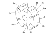
- the rotor 5 includes a field iron core 8, a main field winding 9 and a sub-field winding 10 wound around the field iron core 8.
- the field iron core 8 is provided with a plurality of tooth-shaped magnetic pole portions 8b protruding in the circumferential direction on the outer periphery of an iron core body 8a having a center hole.
- Three magnetic pole portions 8 b are provided for each magnetic pole portion 6 b of the output iron core 6.
- the main field winding 9 is wound over two adjacent magnetic pole portions 8b and 8b.
- the main field windings 9 wound around the two magnetic pole portions 8b and 8b are connected in series so that different magnetic poles appear on the magnetic pole surfaces of the adjacent magnetic pole sets in pairs. ing.
- the sub-field winding 10 is shifted in phase by the amount of the main field winding 9 and one magnetic pole portion 8b, and is spread over two adjacent magnetic pole portions 8b and 8b in the same manner as the main field winding 9. It is rolled up.
- the sub-field windings 10 wound over the two magnetic pole portions 8b and 8b are connected in series so that different magnetic poles appear on the magnetic pole surfaces of the adjacent magnetic pole pairs in a pair. ing.
- terminals 9a and 9b are formed at both ends of the series connection body of the main field winding 9
- terminals 10a and 10b are formed at both ends of the series connection body of the sub-field winding 10. Is formed.
- the first rectifying element 11 is connected in parallel to the main field winding 9, and a current in a direction that allows the first rectifying element 11 to flow flows through the main field winding 9.
- the subfield winding 10 is connected in series with the main field winding 9, and the second rectifying element 12 is connected in series with the subfield winding 10, and the subfield winding 10 has a main field winding. Only current in the same direction as line 9 flows.
- the arrows in the figure indicate the direction of current flow.
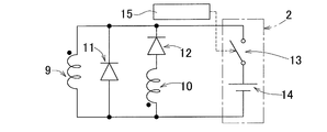
- This generator G is a self-excited generator having such a subfield winding 10 and is provided with a magnetizing means 2 serving as an initial excitation means, as shown in FIG.
- a magnetizing power source 14 is connected to the output winding 7 in parallel with the external load 3 via a switching element 13.
- the magnetizing means 2 is configured by the magnetizing power source 14 and the switching element 13.
- the magnetizing power source 14 is a storage means such as a secondary battery or a capacitor. When the external load 3 is a secondary battery, it may be used as a magnetizing power source.
- a current of a predetermined magnitude may be passed for a very short time.
- the degree of magnetization may be such that residual magnetism necessary for initial excitation for the start of power generation is obtained, and is determined by the voltage and the magnitude of current due to the on-time of the switching element 13.
- the opening / closing operation of the switching element 13 is performed by the opening / closing control means 15.
- the opening / closing control means 15 monitors the detection signal of the rotation detecting means 16 that detects the rotation of the rotor 5, and when it is detected that the rotor 5 has started rotating from a stationary state, the switching element 13 is magnetized. Turn it on only for the required setting time.
- the opening / closing control means 15 turns on the switching element 13 only when the rotation starts after the rotor 5 stops for a set time or longer.
- the switching element 13 may be controlled to be turned on according to the set conditions.
- the magnetizing power source 14 is connected to the output winding 7. However, as shown in FIG. 4, the main field winding 9 and the subfield winding 10 are magnetized via the switching element 13.
- a power source 14 may be connected. Also in this example, the magnetizing power source 14 is a secondary battery or a capacitor. In order to magnetize, a current of a predetermined magnitude may be passed for a very short time.
- the switching element 13 is controlled to be opened and closed by the opening / closing control means 15 as in the embodiment of FIG.
- the operation of the first embodiment will be described.
- the operation when the rotor 5 is rotating and generating power will be described.
- a current in a direction that allows the first rectifying element 11 to flow through the main field winding 9. Flows. Therefore, a magnetic flux having a direction determined by a current that can be passed through the main field winding 9 is generated.
- due to electromagnetic induction a current flows in a direction that prevents a decrease in magnetic flux in the same direction as a magnetic flux generated by the current, but a current does not flow in a direction that prevents an increase in magnetic flux. Therefore, the decrease of the magnetic flux is prevented, but the increase of the magnetic flux is not prevented.
- a second rectifying element 12 is connected in series to the subfield winding 10, and only a current in the same direction as the main field winding 9 flows.
- the current flows through the main field winding 9 due to the residual magnetism of the output core 6 or the field core 8. With this current, the magnetic flux generated by the main field winding 9 changes the magnetic flux linked to the sub field winding 10, and a voltage is generated in the sub field winding 10. With this voltage, the sub-field winding 10 supplies a current through the main field winding 9 and increases the current flowing through the main field winding 9. When no current is supplied to the subfield winding 10 without inducing voltage, a return current flows through the commutator 11 in the main field winding 9 to maintain the magnetic flux of the main field winding 9.
- the magnetic flux linked to the subfield winding 10 is also increased, and a larger current is supplied to the main field winding 9. 9 is supplied. In this manner, the current in the main field winding 9 gradually increases, and a field magnetic flux necessary for power generation is created. Due to the relative motion of the output iron core 6 and the field iron core 8, the flux linkage of the output winding 7 changes to generate a voltage.
- the switching element 13 of the magnetizing means 2 is turned on to pass a magnetizing current from the magnetizing power source 14 to the output winding 7, and the output iron core 6. Magnetize. Since the magnetic flux gradually increases as the rotation continues as described above, the degree of magnetization may be such that the residual magnetism necessary for the initial excitation for the start of power generation is obtained. For this reason, in order to magnetize, a current of a predetermined magnitude may be passed for a very short time. By this magnetization, even after the rotor 5 is stopped for a long time, power generation is reliably started by resuming the rotation.
- the switching element 13 of the magnetizing means 2 is turned on and a magnetizing current is supplied from the magnetizing power supply 14 to the main field winding 9.
- the field iron core 8 is magnetized. Even when the field core 8 is magnetized in this way, power generation is started even after the rotor 5 has been stopped for a long time.
- the generator G configured as shown in FIG. 4, the following advantages are obtained. Since it is a self-excited type that performs excitation using the sub-field winding 10, power generation can be performed without the need for a permanent magnet or an external power source that supplies power for external excitation from the outside. Since no permanent magnet is used, no cogging torque is generated and the rotor 5 can be rotated with a small torque. Although it is self-excited, the magnetizing means 2 for magnetizing one of the iron cores of the generator G is provided to such an extent that a magnetic force required for initial excitation of power generation can be generated. Even after maintenance and at low speed, power generation can be started reliably. Although the magnetizing means 2 is necessary, the magnetizing means 2 is sufficient if it can be magnetized to such an extent that it can generate a magnetic force necessary for initial excitation of power generation. Compared to an external power source in, it can be much smaller.
- FIGS. 5 and 6 show still another embodiment of the present invention.
- This embodiment is an example in which, in the first embodiment shown in FIGS. 1 to 3, an initial exciting magnet 31 is provided instead of the magnetizing means 2 for the initial exciting means.
- the initial excitation magnet 31 is embedded in the field core 8 as shown in FIG.
- the initial excitation magnet 31 is a permanent magnet that generates a magnetic force necessary for initial excitation of power generation, and a magnet that is as small as possible is used in a range that allows for a margin so that the magnetic force necessary for initial excitation can be reliably generated.
- a ferrite magnet that is less expensive than a rare earth magnet can be used.
- the initial excitation magnet 31 has a direction in which the direction of the generated magnetic flux is the same as the direction of the magnetic flux generated by the excitation current flowing in the main field winding 9.
- the number of the initial excitation magnets 31 is the same as the number of the magnetic pole portions 6b of the output iron core 6, and is two, but may be one.
- the magnetic pole part 6b of the output iron core 6 is 4 poles, 8 poles, or 16 poles, the number may be two or the number according to the number of magnetic poles.
- the initial excitation magnet 31 is provided over the entire axial thickness of the magnetic pole portion 8b from which the field core 8 protrudes, as in the example of FIG.
- the initial excitation magnet 31 is divided into two divided magnetic pole portions 8ba and 8ba arranged in the circumferential direction of the magnetic pole portion 8b of the field iron core 8, and interposed between the two divided magnetic pole portions 8ba and 8ba. ing.
- the initial excitation magnet 31 may be embedded in a surface 8 bb of the magnetic pole portion 8 b of the field core 8 that faces the output core 6.
- the initial excitation magnet 31 is embedded in the center of the facing surface 8bb of the magnetic pole portion 8b.
- the operation of the generator G according to this embodiment will be described. Since the operation of the generator G during continuous rotation is the same as that in the first embodiment, description thereof is omitted.
- power is generated while the rotor 5 is rotating. However, if the rotor 5 is stopped for a long time, both the output iron core 6 and the field iron core 8 There is no residual magnetism, or the residual magnetism is insufficient and power generation cannot be started. Therefore, in this embodiment, the initial excitation magnet 31 is provided, and the power generation is reliably started by resuming the rotation even after the rotor 5 is stopped for a long time by the magnetic flux generated by the initial excitation magnet 31. .
- the generator G having this configuration provides the following advantages. Since it is a self-excited type that performs excitation using the sub-field winding 10, power generation can be performed without the need for a permanent magnet for power generation or an external power source that supplies power for external excitation from the outside. Since no permanent magnet for power generation is used, no cogging torque is generated and the rotor 5 can be rotated with a small torque. Although self-excited, the initial excitation magnet 31 is provided in the field core 8 so that power generation can be reliably started even after rotation is stopped, after disassembly and maintenance, or at low speed. Can do.
- the initial excitation magnet 31 is provided, in the self-excited generator, the magnetic flux increases as it rotates as described above. Therefore, the magnetic force required for the initial excitation is very small. Since the magnet 31 for initial excitation is a permanent magnet that generates a magnetic force necessary for such a small initial excitation, it may be a magnet that generates a very weak magnetic force as compared with a permanent magnet that obtains normal generated power. Therefore, an expensive rare metal is unnecessary, an inexpensive material such as a ferrite magnet is sufficient, a small magnet is sufficient, and the cogging torque is not a problem in practical use. Moreover, unlike a reluctance generator, since it is an improvement of a self-excited generator, it is easy to put it into practical use.
- stator 4 side is the output iron core 6 and the rotor 5 side is the field iron core 8. Conversely, the stator 4 side is the field iron core 8, and the rotor 5 side is the output iron core 6. Also good.
- a two-pole generator is used, but a multi-pole generator such as a 4-pole, 8-pole, or 16-pole generator may be used.
- the magnetizing means 2 or the initial exciting magnet 31 is provided as the initial exciting means.
- the magnetizing is not performed, but to the extent necessary for the initial excitation of power generation, Means (not shown) for applying a current to any of the windings 7, 8, 9 for a predetermined time at the beginning of rotation so that a magnetic force is generated in one or both of the output core 6 and the field core 8. ) May be provided.
- FIG. 8 shows an example in which the stator 4 side is a field iron core 8 and the rotor 5 side is an output iron core 6 to form a quadrupole generator. Since the principle is the same as that of the first embodiment, the same reference numerals are assigned to the corresponding parts and the description thereof is omitted.
- the initial excitation means is not shown.
- the initial excitation means may be the magnetizing means 2 or the initial excitation magnet 31. When the initial excitation magnet 31 is used, it is provided on the stator 4 side in this embodiment.
- the rotor 5 is attached to a shaft 21 and is rotatably supported by a bearing 23 with respect to the frame 22 together with the shaft 21.
- the stator 4 is fixed to the frame 22.
- the output winding of the rotor 5 is taken out to the fixed side via the slip ring 24 and the brush 25.
- FIG. 10 shows a breakage of the generator G according to the embodiment of FIG. 1 or FIG. 4 or the wind power generator W in which the generator G according to any of the embodiments of FIGS. 5 to 8 is mounted as a generator for wind power generation. It is a side view.
- a nacelle 42 is provided on a support base 41 so as to be horizontally rotatable.
- a main shaft 45 is rotatably supported by a bearing 44.
- a blade (windmill) 46 that is a swirl blade is attached to one end of the main shaft 45 protruding from the casing 43.
- the other end of the main shaft 45 is connected to a speed increaser 47, and an output shaft 48 of the speed increaser 47 is coupled to a rotor shaft of a generator G that is a wind power generator. In this way, the rotor of the generator G is rotationally driven by the blade 46.
- the generator G as a wind power generator, it is possible to start rotation even with a light torque, and to generate power even at a low speed, and in wind power generation using natural forces with large fluctuations. , Can generate electricity efficiently.
- the generator G according to each of the above embodiments can be used for power generation of various energy sources such as power generation using running water and power generation using other natural forces in addition to wind power generation.
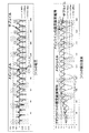
- FIGS. 11 to 13 show the results of trial manufacture and magnetic field analysis of the generator configured as shown in FIGS.
- FIG. 11 shows the rising waveform of the coil voltage and the linkage flux by magnetic field analysis. From this figure, it can be seen that the linkage flux of the main coil gradually increases.
- the “main coil” in the figure corresponds to the “main field winding 9” in the embodiment, and the “subcoil” corresponds to the “sub field winding 10” in the embodiment.
- the “rotor coil” corresponds to the “output winding 7”. From FIG. 12 and FIG. 13, the change in the magnetic flux density of each part due to the rotation of the rotor 5 is known.
Landscapes
- Engineering & Computer Science (AREA)
- Power Engineering (AREA)
- Life Sciences & Earth Sciences (AREA)
- Sustainable Development (AREA)
- Sustainable Energy (AREA)
- Chemical & Material Sciences (AREA)
- Combustion & Propulsion (AREA)
- Mechanical Engineering (AREA)
- General Engineering & Computer Science (AREA)
- Synchronous Machinery (AREA)
- Permanent Field Magnets Of Synchronous Machinery (AREA)
Abstract
La présente invention concerne un générateur automatique (G) comportant: un noyau de sortie (6) ayant un enroulement de sortie (7) enroulé sur celui-ci; et un noyau de champ (8) ayant un enroulement de champ principal (9) et un enroulement de champ auxiliaire (10) enroulés sur celui-ci. Un parmi le noyau de sortie (6) et le noyau de champ (8) devient un stator (4) et l'autre devient un rotor (5). Un premier élément redresseur (11) est connecté à l'enroulement de champ principal (9) et un second élément redresseur (12) est connecté à l'enroulement de champ auxiliaire (10). L'énergie est générée par la rotation relative entre le stator (4) et le rotor (5). Des moyens d'excitation initiale (2, 31) sont prévus qui appliquent une force magnétique soit au noyau de sortie (6) soit au noyau de champ (8) soit aux deux à la fois, en une quantité nécessaire pour l'excitation initiale pour la production d'énergie.
Priority Applications (3)
| Application Number | Priority Date | Filing Date | Title |
|---|---|---|---|
| EP15825372.4A EP3174194A4 (fr) | 2014-07-24 | 2015-07-16 | Générateur |
| CN201580039574.2A CN106537758A (zh) | 2014-07-24 | 2015-07-16 | 发电机 |
| US15/412,677 US20170133916A1 (en) | 2014-07-24 | 2017-01-23 | Generator |
Applications Claiming Priority (6)
| Application Number | Priority Date | Filing Date | Title |
|---|---|---|---|
| JP2014-150684 | 2014-07-24 | ||
| JP2014150684A JP2016025815A (ja) | 2014-07-24 | 2014-07-24 | 発電機 |
| JP2014150442A JP2016025811A (ja) | 2014-07-24 | 2014-07-24 | 発電機 |
| JP2014-150442 | 2014-07-24 | ||
| JP2014163438A JP2016039747A (ja) | 2014-08-11 | 2014-08-11 | 風力発電用発電機 |
| JP2014-163438 | 2014-08-11 |
Related Child Applications (1)
| Application Number | Title | Priority Date | Filing Date |
|---|---|---|---|
| US15/412,677 Continuation US20170133916A1 (en) | 2014-07-24 | 2017-01-23 | Generator |
Publications (1)
| Publication Number | Publication Date |
|---|---|
| WO2016013477A1 true WO2016013477A1 (fr) | 2016-01-28 |
Family
ID=55163003
Family Applications (1)
| Application Number | Title | Priority Date | Filing Date |
|---|---|---|---|
| PCT/JP2015/070375 Ceased WO2016013477A1 (fr) | 2014-07-24 | 2015-07-16 | Generateur |
Country Status (4)
| Country | Link |
|---|---|
| US (1) | US20170133916A1 (fr) |
| EP (1) | EP3174194A4 (fr) |
| CN (1) | CN106537758A (fr) |
| WO (1) | WO2016013477A1 (fr) |
Families Citing this family (2)
| Publication number | Priority date | Publication date | Assignee | Title |
|---|---|---|---|---|
| JP2019534661A (ja) * | 2016-10-04 | 2019-11-28 | ホルコンブ サイエンティフィック リサーチ リミテッド | Ac/dc発電機向けソリッドステート多極および単極発電機ロータ |
| CN110729829B (zh) * | 2019-10-23 | 2020-12-04 | 温岭绿能新能源有限公司 | 发电机的磁阻调整方法 |
Citations (4)
| Publication number | Priority date | Publication date | Assignee | Title |
|---|---|---|---|---|
| JPS50106122A (fr) * | 1973-08-03 | 1975-08-21 | ||
| JPS54140113A (en) * | 1978-04-24 | 1979-10-31 | Nippon Denso Co Ltd | Self excited alternating current generator |
| JPS6181771U (fr) * | 1984-10-31 | 1986-05-30 | ||
| JPH0716000A (ja) * | 1993-06-22 | 1995-01-17 | Hitachi Ltd | 不平衡負荷補償発電システム |
Family Cites Families (17)
| Publication number | Priority date | Publication date | Assignee | Title |
|---|---|---|---|---|
| GB757304A (en) * | 1951-09-24 | 1956-09-19 | Macfarlane Engineering Company | Improvements in electric generators |
| FR1399717A (fr) * | 1964-04-09 | 1965-05-21 | Bronzavia Sa | Procédé et dispositif pour la commande et la régulation de la tension nominale d'un alternateur asynchrone |
| CH546509A (de) * | 1972-06-26 | 1974-02-28 | Bbc Brown Boveri & Cie | Elektronische schaltungsanordnung zur erregung eines asynchron anlaufenden, schleifringlosen synchronmotors. |
| DE2650851A1 (de) * | 1976-11-06 | 1978-05-11 | Bosch Gmbh Robert | Stromversorgungseinrichtung fuer eine zweispannungsanlage in einem kraftfahrzeug |
| DE2920101A1 (de) * | 1979-05-18 | 1980-11-27 | Bosch Gmbh Robert | Vorrichtung zur erregung von drehstromgeneratoren |
| SU868937A1 (ru) * | 1980-01-24 | 1981-09-30 | Предприятие П/Я А-7376 | Самовозбуждающийс двухчастотный генератор |
| US4499530A (en) * | 1981-09-30 | 1985-02-12 | Hitachi, Ltd. | Switching power supply apparatus |
| JPS6135126A (ja) * | 1984-07-24 | 1986-02-19 | 株式会社日立製作所 | 発電機の制御装置 |
| JPH01264551A (ja) * | 1988-04-12 | 1989-10-20 | Shindaiwa Kogyo Kk | ブラシレス自励同期発電機 |
| JP3165968B2 (ja) * | 1991-05-22 | 2001-05-14 | 新ダイワ工業株式会社 | ブラシレス同期機 |
| JPH077900A (ja) * | 1993-05-24 | 1995-01-10 | Tadashi Fukami | ブラシレス三相同期発電機 |
| US6586914B2 (en) * | 2001-11-19 | 2003-07-01 | General Electric Company | Wound field synchronous machine control system and method |
| WO2007032233A1 (fr) * | 2005-09-15 | 2007-03-22 | Murata Manufacturing Co., Ltd. | Convertisseur direct de type à redressement par synchronisation |
| CN1770581A (zh) * | 2005-10-11 | 2006-05-10 | 横店得邦电子有限公司 | 一种单路综合保护电路 |
| WO2007046195A1 (fr) * | 2005-10-19 | 2007-04-26 | Murata Manufacturing Co., Ltd. | Convertisseur pour rectification synchrone |
| CN102340224A (zh) * | 2011-06-30 | 2012-02-01 | 无锡星诺电气有限公司 | 5kw发电电焊机的自励装置 |
| US9252695B2 (en) * | 2014-03-12 | 2016-02-02 | General Electric Company | Brushless permanent magnet generator plus auxiliary voltage source constant potential exciter |
-
2015
- 2015-07-16 CN CN201580039574.2A patent/CN106537758A/zh active Pending
- 2015-07-16 WO PCT/JP2015/070375 patent/WO2016013477A1/fr not_active Ceased
- 2015-07-16 EP EP15825372.4A patent/EP3174194A4/fr not_active Withdrawn
-
2017
- 2017-01-23 US US15/412,677 patent/US20170133916A1/en not_active Abandoned
Patent Citations (4)
| Publication number | Priority date | Publication date | Assignee | Title |
|---|---|---|---|---|
| JPS50106122A (fr) * | 1973-08-03 | 1975-08-21 | ||
| JPS54140113A (en) * | 1978-04-24 | 1979-10-31 | Nippon Denso Co Ltd | Self excited alternating current generator |
| JPS6181771U (fr) * | 1984-10-31 | 1986-05-30 | ||
| JPH0716000A (ja) * | 1993-06-22 | 1995-01-17 | Hitachi Ltd | 不平衡負荷補償発電システム |
Non-Patent Citations (1)
| Title |
|---|
| See also references of EP3174194A4 * |
Also Published As
| Publication number | Publication date |
|---|---|
| EP3174194A4 (fr) | 2018-02-28 |
| EP3174194A1 (fr) | 2017-05-31 |
| US20170133916A1 (en) | 2017-05-11 |
| CN106537758A (zh) | 2017-03-22 |
Similar Documents
| Publication | Publication Date | Title |
|---|---|---|
| JP6541145B2 (ja) | 低温用フェライト磁石モーターを加熱するためのシステムおよび方法 | |
| JP5216686B2 (ja) | 永久磁石形発電機 | |
| JP2013055789A (ja) | 電動発電機 | |
| CN107196477B (zh) | 旋转电机 | |
| CN101291095A (zh) | 混合式开关磁阻电机 | |
| EP2493055B1 (fr) | Machine rotative électrique à aimant permanent | |
| CN107591979A (zh) | 转子轴向磁化永磁开关磁阻电机 | |
| KR101238855B1 (ko) | 이중 공극형 발전기 | |
| WO2019098341A1 (fr) | Alternateur synchrone sans balai | |
| US8922154B2 (en) | Brushless starter-generator assembly and method to control magnetic flux excitation | |
| WO2016013477A1 (fr) | Generateur | |
| JP2016025811A (ja) | 発電機 | |
| CN104505961A (zh) | 一种外转子电动发电机 | |
| JP2016039747A (ja) | 風力発電用発電機 | |
| JP2016169711A (ja) | 風力発電用の風車および風力発電機 | |
| JP2016067128A (ja) | 発電機 | |
| JP6444676B2 (ja) | 発電機 | |
| KR20120057531A (ko) | 비자성 회전자 이너 아우터 고정자 발전기의 구조 | |
| JP2016025815A (ja) | 発電機 | |
| RU2379546C1 (ru) | Статор ветроэлектрогенератора | |
| JP6444677B2 (ja) | 発電機 | |
| JP6396146B2 (ja) | 発電機 | |
| DK181215B1 (en) | System adapted for operating generator | |
| US20070132333A1 (en) | Self magnetizing motor and method for winding coils on stator thereof | |
| JP2018207628A (ja) | 風力発電機 |
Legal Events
| Date | Code | Title | Description |
|---|---|---|---|
| 121 | Ep: the epo has been informed by wipo that ep was designated in this application |
Ref document number: 15825372 Country of ref document: EP Kind code of ref document: A1 |
|
| REEP | Request for entry into the european phase |
Ref document number: 2015825372 Country of ref document: EP |
|
| WWE | Wipo information: entry into national phase |
Ref document number: 2015825372 Country of ref document: EP |
|
| NENP | Non-entry into the national phase |
Ref country code: DE |