WO2016013623A1 - Dispositif de mesure de débit et procédé de mesure de débit - Google Patents
Dispositif de mesure de débit et procédé de mesure de débit Download PDFInfo
- Publication number
- WO2016013623A1 WO2016013623A1 PCT/JP2015/070993 JP2015070993W WO2016013623A1 WO 2016013623 A1 WO2016013623 A1 WO 2016013623A1 JP 2015070993 W JP2015070993 W JP 2015070993W WO 2016013623 A1 WO2016013623 A1 WO 2016013623A1
- Authority
- WO
- WIPO (PCT)
- Prior art keywords
- pipe
- flow rate
- ultrasonic
- ultrasonic wave
- ultrasonic transducer
- Prior art date
- Legal status (The legal status is an assumption and is not a legal conclusion. Google has not performed a legal analysis and makes no representation as to the accuracy of the status listed.)
- Ceased
Links
Images


Classifications
-
- G—PHYSICS
- G01—MEASURING; TESTING
- G01F—MEASURING VOLUME, VOLUME FLOW, MASS FLOW OR LIQUID LEVEL; METERING BY VOLUME
- G01F1/00—Measuring the volume flow or mass flow of fluid or fluent solid material wherein the fluid passes through a meter in a continuous flow
- G01F1/66—Measuring the volume flow or mass flow of fluid or fluent solid material wherein the fluid passes through a meter in a continuous flow by measuring frequency, phase shift or propagation time of electromagnetic or other waves, e.g. using ultrasonic flowmeters
- G01F1/662—Constructional details
-
- G—PHYSICS
- G01—MEASURING; TESTING
- G01F—MEASURING VOLUME, VOLUME FLOW, MASS FLOW OR LIQUID LEVEL; METERING BY VOLUME
- G01F1/00—Measuring the volume flow or mass flow of fluid or fluent solid material wherein the fluid passes through a meter in a continuous flow
- G01F1/66—Measuring the volume flow or mass flow of fluid or fluent solid material wherein the fluid passes through a meter in a continuous flow by measuring frequency, phase shift or propagation time of electromagnetic or other waves, e.g. using ultrasonic flowmeters
- G01F1/667—Arrangements of transducers for ultrasonic flowmeters; Circuits for operating ultrasonic flowmeters
Definitions
- the present invention relates to a flow rate measuring device and a flow rate measuring method.
- This application claims priority based on Japanese Patent Application No. 2014-150141 for which it applied on July 23, 2014, and uses the content here.
- the aspect of the present invention provides a flow rate measurement device and a flow rate measurement method that are excellent in versatility and that can accurately measure the flow rate of gas flowing in a pipe even under different measurement conditions.
- a flow rate measuring device for measuring a flow rate of a gas flowing inside a pipe, the ultrasonic transducer being installed in contact with the pipe, and an ultrasonic wave generated by the ultrasonic transducer.
- a flow rate calculation unit that calculates a flow rate of the gas based on a reception result, the ultrasonic transducer, an ultrasonic oscillation unit that oscillates the ultrasonic wave toward the inside of the pipe, and the ultrasonic wave
- An ultrasonic receiving unit for receiving, and at least the ultrasonic wave oscillating unit has a converging means for converging the ultrasonic wave to the center of the pipe.
- the convergence means may have a curvature in which the ultrasonic oscillation surface corresponds to an outer surface of the pipe.
- the ultrasonic receiving unit may have a second converging unit, and the second converging unit has a curvature corresponding to an outer surface of the pipe. You may have.
- a vibration suppressor provided in the pipe may be further provided.
- the first aspect may further include a removable spacer member between the pipe and the ultrasonic transducer, and the spacer member has an inner diameter equivalent to the curvature of the outer surface of the pipe. You may have an outer diameter equivalent to the curvature of the said oscillation surface.
- the determination unit that determines the deviation of the flow velocity distribution of the gas inside the pipe based on the measurement results of the plurality of ultrasonic transducers installed at a plurality of locations in the circumferential direction of the pipe.
- a selection unit that selects a plurality of ultrasonic transducers to be used for measurement based on the determination result of the determination unit.
- the center frequency of the ultrasonic wave by the ultrasonic transducer may be set to 100 kHz to 1 MHz.
- the gas flow rate may be measured using a tuft method.
- a flow rate measurement method is a flow rate measurement method for measuring a flow rate of a gas flowing inside a pipe, and includes an ultrasonic oscillator that oscillates an ultrasonic wave toward the inside of the pipe, An ultrasonic receiving unit that receives the ultrasonic wave oscillated by an ultrasonic oscillating unit, and at least the ultrasonic oscillating unit includes an ultrasonic transducer that has a converging means for converging the ultrasonic wave at the center of the pipe, A receiving step for receiving an ultrasonic wave oscillated toward the inside of the pipe; and a flow rate calculating step for calculating the flow rate of the gas based on the result received in the receiving step.
- the convergence means in which the ultrasonic oscillation surface has a curvature corresponding to the outer surface of the pipe may be used as the ultrasonic transducer.
- the ultrasonic receiving unit having second converging means may be used as the ultrasonic transducer, and the second converging means is the ultrasonic wave receiving surface. May have a curvature corresponding to the outer surface of the pipe.
- a vibration suppressor may be disposed in the pipe.
- the deviation of the flow velocity distribution of the said gas in the said piping is determined. You may provide the determination step and the selection step which selects the said ultrasonic transducer used by the said reception step based on the result of the said determination step.
- the ultrasonic transducer having a center frequency of 100 kHz to 1 MHz may be used.
- the gas flow rate may be measured using a tuft method.
- the aspect of the present invention it is excellent in versatility, and it is possible to accurately measure the flow rate of the gas flowing in the piping under different measurement conditions.
- the flow rate measuring device is a system capable of measuring the flow rate of gas (for example, steam) flowing in a pipe, which is disposed between a steam production device such as a boiler and load equipment, for example.
- the flow rate measuring device of the present embodiment is a device that measures the flow rate of the gas flowing in the pipe using ultrasonic waves.
- FIG. 1 is a diagram showing a schematic configuration of a flow rate measuring apparatus according to the present embodiment.
- FIG. 2A and FIG. 2B are diagrams showing the main configuration of the flow rate measuring device.
- the flow measuring device 100 includes an ultrasonic transducer 1 and a control unit 2.
- a pipe 10 is disposed between a steam production apparatus 20 (such as a boiler) and a load facility 30. Steam from the steam production apparatus 20 flows through the pipe 10 and is sent to the load facility 30. In the load facility 30, steam or steam heat is used. The steam discharged from the load facility 30 is collected as a drain, collected in a return water tank (not shown), and then supplied again to the steam production apparatus 20.
- the ultrasonic transmission / reception paths are the pipe material (solid), the liquid, and the pipe material (solid).
- the solid and liquid have relatively good acoustic impedance matching, which is the product of the sound speed and density of the medium. That is, the density ratio and sound speed ratio of the solid and the liquid are about several to ten times.
- conventional ultrasonic transducers used for flow measurement consisted of a flat sensor with a flat vibration surface.
- the flat sensor is easy to receive a guide wave (noise component) propagating through the pipe. Therefore, when a flat sensor is used for the above-described clamp-on type gas flow rate measurement, it is difficult to accurately transmit and receive ultrasonic signals, and it is difficult to accurately measure the flow rate.
- the present inventors have found that the shape of the ultrasonic transducer (sensor) is important in order to efficiently guide the ultrasonic wave into the pipe when measuring the flow rate of the gas flowing in the pipe by the clamp-on method. Obtained.
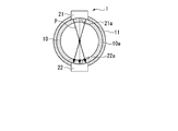
- FIG. 2A and 2B are diagrams showing a schematic configuration of the ultrasonic transducer 1.
- FIG. FIG. 2A is a cross-sectional view of the pipe 10 along the pipe axis direction.
- FIG. 2B is a cross-sectional view of the pipe 10 viewed from the pipe axis direction.
- the ultrasonic transducer 1 is installed in contact with the surface 10a of the pipe 10 (clamp-on method).
- the ultrasonic transducer 1 includes a first element 21 and a second element 22.
- the first element 21 and the second element 22 can transmit and receive ultrasonic waves, respectively.
- An arrow Z in FIG. 2A indicates the direction in which the steam flows.
- the first element 21 functions as an ultrasonic oscillator that oscillates the ultrasonic wave P toward the inside of the pipe 10.
- the second element 22 functions as an ultrasonic receiver that receives the ultrasonic wave P oscillated by the first element 21.
- the center frequency is preferably several tens of kHz to several MHz.
- the influence of environmental noise falls that a center frequency is several hundred kHz or more.
- the attenuation factor in the air of an ultrasonic wave falls that a center frequency is several MHz or less.
- the center frequency is set to 100 kHz to 1 MHz, for example, 500 kHz.
- the first element 21 and the second element 22 of the present embodiment are configured by curved surface sensors having a curvature corresponding to the surface 10a of the pipe 10 in order to efficiently guide the ultrasonic wave P into the pipe 10.
- the oscillation surface 21 a that oscillates an ultrasonic wave has a curved surface (the cross-sectional shape is circular) corresponding to the surface 10 a of the pipe 10. That is, the oscillating surface 21 a can converge the oscillated ultrasonic wave to the center of the pipe 10 by arranging the ultrasonic oscillating elements in a curved surface shape.
- the oscillation surface 21 a constitutes a converging unit that converges the ultrasonic wave at the center of the pipe 10.
- the receiving surface 22a for receiving ultrasonic waves is a curved surface (the cross-sectional shape is circular) corresponding to the surface 10a of the pipe 10. Therefore, the ultrasonic wave converged on the center of the pipe 10 is incident perpendicularly to the receiving surface 22a.
- the mode in which the oscillation surface 21a and the reception surface 22a correspond to the surface 10a is not limited to the mode in which the oscillation surface 21a and the reception surface 22a are in direct contact with the surface 10a.
- it includes a mode in which the oscillating surface 21 a and the receiving surface 22 a are indirectly in contact with the surface 10 a by arranging a wedge-shaped spacer member in the gap between the ultrasonic transducer 1 and the pipe 10.
- FIG. 3 is a diagram showing a schematic configuration of the spacer member.
- the spacer member 13 has an inner diameter 13a that matches the curvature of the surface 10a, and an outer diameter 13b that matches the curvatures of the oscillation surface 21a and the receiving surface 22a.
- the flow measuring device 100 excellent in versatility independent of the diameter of the pipe 10 is provided.
- the pipe 10 is partially covered with the damping material 11.
- the damping material 11 is installed over the pipe axis direction of the pipe 10 so as to exclude the installation portion of the ultrasonic transducer 1 (the first element 21 and the second element 22).
- the damping material 11 may be a member having a high acoustic attenuation effect, and examples thereof include a clay-like or paste-like material, a sound-absorbing material (punching metal), and a polymer material. Further, when the surface temperature of the pipe 10 increases due to the flow of steam inside, it is desirable to use a material having heat resistance in addition to the acoustic damping effect as the damping material 11.
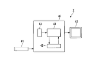
- FIG. 4 is a schematic diagram showing the configuration of the control unit 2.
- the control unit 2 includes an input device 41 and a display device (output device) 42 in addition to the calculation device 40.
- the calculation device 40 includes a converter 43 such as an A / D converter, a CPU (arithmetic processing means) 44, a memory 45, and the like.
- Measurement data (ultrasonic measurement result) sent from the ultrasonic transducer 1 of the flow measuring device 100 is converted by the converter 43 or the like as necessary, and is taken into the CPU 44.
- initial setting values, temporary data, and the like are taken into the calculation device 40 via the input device 41 and the like.
- the display device 42 can display information related to input data, information related to calculation, and the like.
- the CPU 44 can calculate the flow rate of the steam flowing in the pipe 10 based on the measurement data and information stored in the memory 45.
- the CPU 44 for example, the steam flow rate obtained using the reception result of the ultrasonic transducer 1 (the spatial distribution of the ultrasonic waves in the pipe 10) and the information stored in the memory 45 as described later (the cross-sectional area of the pipe 10).
- the flow rate of the steam flowing in the pipe 10 is calculated from the density of the steam).
- the control unit 2 constitutes a flow rate calculation unit (a flow rate calculation unit described in claims) that calculates the flow rate of the steam flowing through the pipe 10.
- the flow measurement method of the flow measurement device 100 can be applied to either the tuft method or the time difference method.
- the tuft method is a method in which ultrasonic waves are oscillated parallel to the pipe cross section, that is, perpendicular to the pipe axis, and the flow rate is determined from the amount of spatial movement of the acoustic intensity distribution by a sensor provided at an opposite position.
- the time difference method two ultrasonic transceivers are installed obliquely with respect to the pipe axis of the pipe, the arrival time of the ultrasonic wave going from upstream to downstream, and the arrival time of the ultrasonic wave going from downstream to upstream This is a method for determining the flow rate from the change in arrival time according to the velocity of the gas.
- the flow rate measuring device 100 of the present embodiment takes a flow rate measurement by a tuft method.
- the ultrasonic waves are vertically incident on the pipe 10 as described above, the ultrasonic waves can be favorably incident inside the pipe 10 by suppressing reflection and refraction at the interface.
- the effectiveness of the flow measurement device 100 of the present embodiment will be described using an analysis result of a simulation of an ultrasonic signal that can be received when ultrasonic flow measurement is performed by the clamp-on method.
- This simulation was performed by modeling the case of measurement by the tuft method.
- the voxel type finite element method is used, the physical properties such as the pipe inner diameter, outer diameter, and material are the same as those of the flow measuring device 100, and the ultrasonic signal is a burst wave that transmits intermittent sine waves at a constant period. It was.
- the sound velocity and density of the steam are important physical property values. Since the sound speed of steam depends on pressure and temperature, the sound speed of saturated steam was calculated using steam as a complete gas.
- FIG. 5 is a diagram showing an analysis result when a conventional flat sensor is used.
- FIG. 6 is a view showing an analysis result when the ultrasonic transducer 1 (curved surface sensor) of the present embodiment is used.
- FIG. 7 is a diagram showing an analysis result when the damping material 11 is installed in addition to the ultrasonic transducer 1 (curved surface sensor) (that is, the configuration of the flow rate measuring device 100 of the present embodiment). 5 to 7 show the results of ultrasonic wave propagation analysis (sound pressure intensity distribution).
- the first element constituting the ultrasonic transducer 1 even in the measurement by the clamp-on method (non-destructive inspection) without cutting the pipe.
- Reference numeral 21 denotes a curved surface sensor corresponding to the surface 10 a of the pipe 10. Therefore, the ultrasonic wave can be converged at the center of the pipe 10. Therefore, since refraction and reflection that are affected by the curvature of the pipe 10 are suppressed, the signal intensity can be improved.
- the second element 22 is composed of a curved surface sensor corresponding to the surface 10 a of the pipe 10. Therefore, the ultrasonic wave converged on the center of the pipe 10 can be made perpendicular to the reception surface 22a.
- the damping material 11 since the damping material 11 is installed in the pipe 10, the sound wave propagating through the pipe 10 is reduced. Therefore, the intensity of the received ultrasonic signal is improved and highly reliable measurement can be performed.
- the control unit 2 starts supplying steam from the steam manufacturing apparatus 20 to the load facility 30 via the pipe 10.
- the control unit 2 drives the ultrasonic transducer 1 to oscillate ultrasonic waves from the oscillation surface 21 a of the first element 21 toward the inside of the pipe 10.
- the first element 21 constituting the ultrasonic transducer 1 has the oscillation surface 21 a having a curvature corresponding to the surface 10 a of the pipe 10. Therefore, refraction and reflection influenced by the curvature of the pipe 10 can be suppressed.
- the ultrasonic wave converged at the center of the pipe 10 is received by the second element 22 installed on the opposite surface side of the pipe 10 (receiving step).
- the second element 22 constituting the ultrasonic transducer 1 since the second element 22 constituting the ultrasonic transducer 1 has the receiving surface 22a having a curvature corresponding to the surface 10a of the pipe 10, the ultrasonic wave converged on the center of the pipe 10 is received with respect to the receiving surface 22a. Can be incident vertically. Therefore, the strength of the received signal is improved, and highly reliable measurement is possible.
- the signal received by the receiving surface 22a is transmitted to the control unit 2.
- the control unit 2 converts the transmitted signal into a digital signal by a converter 43 (see FIG. 4) such as an A / D converter and takes it into the CPU 44 (see FIG. 4).
- the control unit 2 uses the ultrasonic spatial distribution (dispersion data) acquired by the ultrasonic transducer 1 by the tuft method, and uses the information stored in the memory 45 (see FIG. 4) to flow the steam flowing inside the pipe 10. Is calculated (flow rate calculating step).
- the memory 45 stores, for example, information related to the flow velocity of steam and the spatial distribution of ultrasonic waves obtained in advance through experiments, simulations, and the like.
- the control unit 2 reads the information stored in the memory 45 and compares it with the measured value of the ultrasonic spatial distribution of the pipe 10 to obtain the actually measured spatial distribution (measurement result of the ultrasonic transducer 1). The corresponding steam flow rate can be calculated.
- the flow rate of the steam flowing inside the pipe 10 can be easily and accurately obtained without destroying the pipe 10.
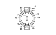
- FIG. 8A and 8B are diagrams showing the main configuration of the flow rate measuring apparatus 101 of the present embodiment.
- FIG. 8A is a cross-sectional view of the pipe 10 along the pipe axis direction.
- FIG. 8B is a cross-sectional view of the pipe 10 viewed from the pipe axis direction.
- the flow rate measuring device 101 of this embodiment includes a plurality of (for example, four) ultrasonic transducers 1 and a control unit 2. Also in the present embodiment, each ultrasonic transducer 1 includes a first element 21 and a second element 22.
- the ultrasonic transducers 1 are arranged so as to be different in position along the circumferential direction of the pipe 10 (with different positions by 40 degrees). Each ultrasonic transducer 1 is electrically connected to the control unit 2 and transmits a measurement result to the control unit 2.
- the control unit 2 causes the first element 21 to function as an ultrasonic oscillation unit and the second element 22 to function as an ultrasonic reception unit in each ultrasonic transducer 1. However, it is possible to cause the first element 21 to function as an ultrasonic wave receiving unit and the second element 22 to function as an ultrasonic wave oscillating unit.
- the flow rate measuring device 101 of the present embodiment can measure the flow rate by ultrasonic waves in four directions within the cross section of the pipe 10.
- the control unit 2 starts supplying steam from the steam manufacturing apparatus 20 to the load facility 30 via the pipe 10.
- the flow velocity distribution is uneven in the pipe 10 or that drain is generated in the lower part of the pipe 10.
- transmission / reception of ultrasonic waves in a direction in which the flow velocity distribution is not biased in the cross section of the pipe 10 (a direction in which no drift occurs) or in a direction in which no drain is generated It becomes possible to perform stable measurement by performing.
- the control unit 2 drives each ultrasonic transducer 1 and acquires the spatial distribution of ultrasonic waves acquired by the ultrasonic transducer 1. Based on the data acquired from the plurality of ultrasonic transducers 1, the control unit 2 obtains a measurement line in which the flow velocity distribution of the steam flowing inside the pipe 10 is biased. That is, the control unit 2 constitutes a determination unit (determination unit described in claims) that determines the deviation of the flow velocity distribution of the steam flowing inside the pipe 10.
- the control unit 2 selects the ultrasonic transducer 1 used for measurement based on the determination result of the flow velocity distribution. That is, the control part 2 comprises the selection part (selection part as described in a claim) which selects the ultrasonic transducer 1 used for a measurement.
- control unit 2 is an ultrasonic transducer capable of transmitting and receiving ultrasonic waves in a direction in which the flow velocity distribution is not biased in the cross section of the pipe 10 or in a direction in which no drain is generated, or in a direction in which the ultrasonic signal reception intensity is strongest. 1 is selected from a plurality. Then, the control unit 2 drives the selected ultrasonic transducer 1.
- the selected ultrasonic transducer 1 oscillates ultrasonic waves from the oscillation surface 21 a of the first element 21 toward the inside of the pipe 10. This oscillated ultrasonic wave is satisfactorily received by the receiving surface 22a of the second element 22 arranged to face the oscillating surface 21a.
- the signal received by the receiving surface 22a is transmitted to the control unit 2.
- the control unit 2 converts the transmitted signal into a digital signal by a converter 43 (see FIG. 4) such as an A / D converter and takes it into the CPU 44 (see FIG. 4).
- the control unit 2 calculates the flow rate of the steam flowing in the pipe 10 from the information stored in the memory 45 (see FIG. 4), using the ultrasonic spatial distribution acquired by the ultrasonic transducer 1 by the tuft method (see FIG. 4). Flow rate calculation step).
- the flow rate measuring device 100 of the present embodiment increases the flow rate of steam (pressure is 8 atm or less) flowing through the pipe 10 having a small diameter (for example, a diameter of 4 inches or less), which has been difficult to measure conventionally. It is possible to measure with accuracy.
- the convergence means for converging the ultrasonic wave at the center of the pipe 10 an example in which the oscillation surface 21 a that oscillates the ultrasonic wave is a curved surface corresponding to the surface 10 a of the pipe 10 is illustrated.
- the present invention is not limited to this.
- an acoustic lens may be used as the convergence means, and the ultrasonic waves may be converged to the center of the pipe 10.
- the case where the flow rate is measured by the tuft method is taken as an example.
- the present invention is not limited to this.
- the present invention can be applied when the flow rate measuring devices 100 and 101 perform flow rate measurement by the time difference method.
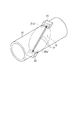
- the first element 21 and the second element 22 transmit and receive ultrasonic waves, respectively.
- the first element 21 and the second element 22 are installed obliquely with respect to the pipe axis direction of the pipe 10 as shown in FIG.
- the ultrasonic wave transmission / reception surface 21 a ′ in the first element 21 transmits and receives the ultrasonic wave P in the plane A that intersects the tube axis direction of the pipe 10.
- the ultrasonic wave transmission / reception surface 22 a ′ of the second element 22 transmits / receives the ultrasonic wave P in the plane A intersecting with the pipe axis direction of the pipe 10.
- the damping material 11 is omitted.
- the transmission / reception surfaces 21a 'and 22a' each have a curved surface corresponding to the surface 10a of the pipe 10, that is, a curved surface whose cross-sectional shape is an ellipse in a plane parallel to the surface A. If the first element 21 and the second element 22 having such a curved surface are used, the ultrasonic wave P can be transmitted and received satisfactorily to the inside of the pipe 10 even when the time difference method is used. Therefore, the flow velocity measurement of the steam flowing through the pipe 10 can be performed with high accuracy.
- a spacer member may be disposed in the gap between the pipe 10 and the ultrasonic transducer 1.
- the ultrasonic transducer 1 by preparing a plurality of spacer members having different sizes, it is possible to perform measurement with excellent versatility capable of performing flow rate measurement on various pipes 10 having different outer diameters even by the time difference method.
- An apparatus is provided.
- the ultrasonic transducer 1 when the flow rate is measured for the pipes 10 having different outer diameters as described above, a flexible one may be used as the ultrasonic transducer 1 instead of the spacer member 13. In this way, since the ultrasonic transducer 1 can be bent easily, it can be reliably installed along the surface 10a regardless of the outer diameter of the pipe 10 by bending according to the curvature of the surface 10a. It becomes. Therefore, it is excellent in versatility capable of performing flow rate measurement on various pipes 10 having different outer diameters.
- the configuration in which the pipe 10 is covered with the vibration damping material 11 has been described as an example, but the present invention is not limited to this.
- the control unit 2 corrects data transmitted from the ultrasonic transducer 1 in consideration of noise components due to sound waves propagating through the pipe 10, the surface 10 a of the pipe 10 is not covered with the damping material 11. May be.
- the case of measuring the flow rate of the steam flowing in the pipe as gas is taken as an example, but the present invention is not limited to this.
- the above-described embodiment can be applied to the case where the flow rate of air flowing through a pipe is measured.
- the gas flowing in the pipe may be chlorofluorocarbon, ammonia, LNG (Liquefied Natural ⁇ Gas), etc., and the present invention is also applicable when measuring the flow rate of these fluids.
- SYMBOLS 1 Ultrasonic transducer, 2 ... Heating part (heat exchanger, heating device), 3 ... Temperature measurement part, 2 ... Control part (Flow rate calculation part, determination part, selection part), 10 ... Piping, 10a ... Surface, 11 ... damping material, 13, 23 ... spacer member, 21 ... first element (ultrasonic oscillator), 21a ... oscillation surface, 22 ... second element (ultrasonic receiver), 22a ... reception surface, 100, 101 ... Flow measurement device.
Landscapes
- Physics & Mathematics (AREA)
- Electromagnetism (AREA)
- Fluid Mechanics (AREA)
- General Physics & Mathematics (AREA)
- Measuring Volume Flow (AREA)
Abstract
L'invention concerne un dispositif de mesure de débit pour mesurer le débit de gaz s'écoulant à l'intérieur d'une tuyauterie. Le dispositif de mesure de débit est pourvu : d'un transducteur ultrasonique mis en contact avec la tuyauterie ; et d'une section de calcul de débit pour calculer le débit du gaz sur la base du résultat de la réception d'ondes ultrasoniques par le transducteur ultrasonique. Le transducteur ultrasonique comprend : une section d'oscillation ultrasonique pour émettre les ondes ultrasoniques vers l'intérieur de la tuyauterie ; et une section de réception ultrasonique pour recevoir les ondes ultrasoniques. Au moins la section d'oscillation ultrasonique possède un moyen de focalisation destiné à focaliser les ondes ultrasoniques au centre de la tuyauterie.
Priority Applications (2)
| Application Number | Priority Date | Filing Date | Title |
|---|---|---|---|
| US15/324,849 US10151610B2 (en) | 2014-07-23 | 2015-07-23 | Flow rate measurement device and flow rate measurement method |
| CN201580039554.5A CN106537098A (zh) | 2014-07-23 | 2015-07-23 | 流量计测装置及流量计测方法 |
Applications Claiming Priority (2)
| Application Number | Priority Date | Filing Date | Title |
|---|---|---|---|
| JP2014150141A JP6582368B2 (ja) | 2014-07-23 | 2014-07-23 | 流量計測装置および流量計測方法 |
| JP2014-150141 | 2014-07-23 |
Publications (1)
| Publication Number | Publication Date |
|---|---|
| WO2016013623A1 true WO2016013623A1 (fr) | 2016-01-28 |
Family
ID=55163147
Family Applications (1)
| Application Number | Title | Priority Date | Filing Date |
|---|---|---|---|
| PCT/JP2015/070993 Ceased WO2016013623A1 (fr) | 2014-07-23 | 2015-07-23 | Dispositif de mesure de débit et procédé de mesure de débit |
Country Status (4)
| Country | Link |
|---|---|
| US (1) | US10151610B2 (fr) |
| JP (1) | JP6582368B2 (fr) |
| CN (1) | CN106537098A (fr) |
| WO (1) | WO2016013623A1 (fr) |
Cited By (2)
| Publication number | Priority date | Publication date | Assignee | Title |
|---|---|---|---|---|
| CN110140221A (zh) * | 2016-12-28 | 2019-08-16 | 夏普株式会社 | Tft基板、具备tft基板的扫描天线以及tft基板的制造方法 |
| CN110462842A (zh) * | 2017-04-07 | 2019-11-15 | 夏普株式会社 | Tft基板、具备tft基板的扫描天线以及tft基板的制造方法 |
Families Citing this family (8)
| Publication number | Priority date | Publication date | Assignee | Title |
|---|---|---|---|---|
| BR112015003632A2 (pt) * | 2012-08-22 | 2017-09-26 | Miitors Aps | medidor ultrassônico de fluxo, método de montagem de um medidor ultrassônico de fluxo. |
| JP6472617B2 (ja) * | 2014-08-06 | 2019-02-20 | 関西電力株式会社 | 気体用外付式超音波流量計及び気体流量計測方法 |
| JP6762013B2 (ja) * | 2016-11-09 | 2020-09-30 | 東京電力ホールディングス株式会社 | 流量計測装置および流量計測方法 |
| EP3521773B1 (fr) * | 2018-02-06 | 2021-09-29 | SICK Engineering GmbH | Dispositif ultrasonore de mesure d'écoulement et procédé de détermination d'une vitesse d'écoulement |
| CN108489562B (zh) * | 2018-02-09 | 2020-10-27 | 杭州软库科技有限公司 | 一种基于超声波共振的水管流速检测水表系统及方法 |
| JP7032842B2 (ja) * | 2018-08-11 | 2022-03-09 | 言欽 李 | パイプ内の軸方向の流速分布と流量を音波法で測定する方法、およびシステム |
| US10739174B2 (en) | 2018-08-11 | 2020-08-11 | Yanqin Li | Method and system of acoustic wave measurement of axial velocity distribution and flow rate |
| CN114387763A (zh) * | 2022-01-21 | 2022-04-22 | 重庆信驰传感技术有限公司 | 一种具有流量、压力、温度和人体感知的燃气切断报警器 |
Citations (8)
| Publication number | Priority date | Publication date | Assignee | Title |
|---|---|---|---|---|
| JPS59161035U (ja) * | 1983-04-14 | 1984-10-29 | オムロン株式会社 | 超音波流量計 |
| JPS6128821A (ja) * | 1984-07-19 | 1986-02-08 | Fuji Electric Corp Res & Dev Ltd | 超音波流量計 |
| JPS6155696A (ja) * | 1984-08-27 | 1986-03-20 | 株式会社 富士電機総合研究所 | 音波吸収体 |
| JPH027524U (fr) * | 1988-06-30 | 1990-01-18 | ||
| JPH02110825U (fr) * | 1989-02-22 | 1990-09-05 | ||
| JPH05264310A (ja) * | 1992-03-19 | 1993-10-12 | Fuji Electric Co Ltd | 超音波流量計 |
| JPH06294671A (ja) * | 1993-04-08 | 1994-10-21 | Kaijo Corp | ドップラー式超音波流量/流速測定装置 |
| JP2000266577A (ja) * | 1999-03-16 | 2000-09-29 | Fuji Electric Co Ltd | 超音波流量計、及びその測定方法 |
Family Cites Families (13)
| Publication number | Priority date | Publication date | Assignee | Title |
|---|---|---|---|---|
| TW295258U (en) * | 1992-10-06 | 1997-01-01 | Caldon Inc | Apparatus for determining fluid flow |
| JP2003254802A (ja) * | 2002-02-28 | 2003-09-10 | Tokico Ltd | 超音波送受信式流量計 |
| US7185547B2 (en) * | 2004-07-09 | 2007-03-06 | Siemens Energy & Automation, Inc. | Extreme temperature clamp-on ultrasonic flowmeter transducer |
| DE102006012114A1 (de) * | 2006-03-14 | 2007-09-20 | Endress + Hauser Flowtec Ag | Vorrichtung zur Bestimmung und/oder Überwachung des Volumen- oder des Massedurchflusses eines Mediums in einer Rohrleitung |
| US7673526B2 (en) * | 2006-11-01 | 2010-03-09 | Expro Meters, Inc. | Apparatus and method of lensing an ultrasonic beam for an ultrasonic flow meter |
| EP2386835B1 (fr) * | 2010-05-12 | 2015-11-25 | SICK Engineering GmbH | Mesure par ultrasons de la vitesse d'écoulement d'un fluide dans une conduite |
| WO2012129101A1 (fr) * | 2011-03-18 | 2012-09-27 | Soneter, LLC | Procédés et appareil pour la mesure d'un écoulement de fluide |
| US9494454B2 (en) * | 2013-12-06 | 2016-11-15 | Joseph Baumoel | Phase controlled variable angle ultrasonic flow meter |
| US9453749B1 (en) * | 2015-03-10 | 2016-09-27 | Honeywell International Inc. | Hybrid sensing ultrasonic flowmeter |
| US9448092B1 (en) * | 2015-09-03 | 2016-09-20 | King Fahd University Of Petroleum And Minerals | Clamp-on ultrasonic fluid flow meter system |
| DE102016108986A1 (de) * | 2016-05-13 | 2017-11-16 | Krohne Messtechnik Gmbh | Verfahren zur Detektion von Rohrleitungsschwingungen und Messgerät |
| EP3246668B1 (fr) * | 2016-05-19 | 2018-07-25 | SICK Engineering GmbH | Dispositif de mesure et procede de determination de la vitesse d'ecoulement d'un fluide s'ecoulant dans une conduite |
| US10222247B2 (en) * | 2016-07-07 | 2019-03-05 | Joseph Baumoel | Multiphase ultrasonic flow meter |
-
2014
- 2014-07-23 JP JP2014150141A patent/JP6582368B2/ja active Active
-
2015
- 2015-07-23 WO PCT/JP2015/070993 patent/WO2016013623A1/fr not_active Ceased
- 2015-07-23 CN CN201580039554.5A patent/CN106537098A/zh active Pending
- 2015-07-23 US US15/324,849 patent/US10151610B2/en active Active
Patent Citations (8)
| Publication number | Priority date | Publication date | Assignee | Title |
|---|---|---|---|---|
| JPS59161035U (ja) * | 1983-04-14 | 1984-10-29 | オムロン株式会社 | 超音波流量計 |
| JPS6128821A (ja) * | 1984-07-19 | 1986-02-08 | Fuji Electric Corp Res & Dev Ltd | 超音波流量計 |
| JPS6155696A (ja) * | 1984-08-27 | 1986-03-20 | 株式会社 富士電機総合研究所 | 音波吸収体 |
| JPH027524U (fr) * | 1988-06-30 | 1990-01-18 | ||
| JPH02110825U (fr) * | 1989-02-22 | 1990-09-05 | ||
| JPH05264310A (ja) * | 1992-03-19 | 1993-10-12 | Fuji Electric Co Ltd | 超音波流量計 |
| JPH06294671A (ja) * | 1993-04-08 | 1994-10-21 | Kaijo Corp | ドップラー式超音波流量/流速測定装置 |
| JP2000266577A (ja) * | 1999-03-16 | 2000-09-29 | Fuji Electric Co Ltd | 超音波流量計、及びその測定方法 |
Cited By (4)
| Publication number | Priority date | Publication date | Assignee | Title |
|---|---|---|---|---|
| CN110140221A (zh) * | 2016-12-28 | 2019-08-16 | 夏普株式会社 | Tft基板、具备tft基板的扫描天线以及tft基板的制造方法 |
| CN110140221B (zh) * | 2016-12-28 | 2022-03-08 | 夏普株式会社 | Tft基板、具备tft基板的扫描天线以及tft基板的制造方法 |
| CN110462842A (zh) * | 2017-04-07 | 2019-11-15 | 夏普株式会社 | Tft基板、具备tft基板的扫描天线以及tft基板的制造方法 |
| CN110462842B (zh) * | 2017-04-07 | 2022-05-17 | 夏普株式会社 | Tft基板、具备tft基板的扫描天线以及tft基板的制造方法 |
Also Published As
| Publication number | Publication date |
|---|---|
| JP2016024131A (ja) | 2016-02-08 |
| US10151610B2 (en) | 2018-12-11 |
| CN106537098A (zh) | 2017-03-22 |
| US20170219400A1 (en) | 2017-08-03 |
| JP6582368B2 (ja) | 2019-10-02 |
Similar Documents
| Publication | Publication Date | Title |
|---|---|---|
| JP6582368B2 (ja) | 流量計測装置および流量計測方法 | |
| KR101798716B1 (ko) | 초음파 유량계 및 유량 계측 방법 | |
| JP6582855B2 (ja) | 流量計測装置および流量計測方法 | |
| CN104236648B (zh) | 超声波流量计 | |
| RU2637381C2 (ru) | Ультразвуковой волновод | |
| JP2015232519A (ja) | クランプオン式超音波流量計及び流量の計測方法 | |
| KR20120108001A (ko) | 초음파 변환기, 유량계 및 방법 | |
| US10890471B2 (en) | Method and assembly for ultrasonic clamp-on flow measurement, and bodies for implementing off-center flow measurement | |
| JP6207428B2 (ja) | 超音波式音速測定装置及び超音波式音速測定方法 | |
| EP3063508B1 (fr) | Débitmètre pour mesure ultrasonique de la vitesse d'écoulement de fluides | |
| EP2657658B1 (fr) | Système de mesure de flux à ultrasons | |
| JP6755485B2 (ja) | 流量計測装置および流量計測方法 | |
| JP7151344B2 (ja) | 圧力計測装置 | |
| JP6762013B2 (ja) | 流量計測装置および流量計測方法 | |
| JP2016109560A (ja) | 流量計測装置および流量計測方法 | |
| KR101119998B1 (ko) | 다회선 외벽부착식 초음파 트랜스듀서 | |
| KR101173372B1 (ko) | 초음파 송수파기 | |
| JP6187661B2 (ja) | 超音波流量計 | |
| JP2010060386A (ja) | 流速測定方法および流速測定装置 | |
| RU2021119988A (ru) | Устройство для измерения расхода текучей среды | |
| JP2007178244A (ja) | 超音波流量計および超音波流量計に用いるくさび | |
| KR20140024992A (ko) | 신호 특성 개선을 위한 u자형 초음파 유량계용 유량 보정핀 | |
| JP2005345358A (ja) | 超音波流量計およびそれに用いるくさび | |
| JP2005195372A (ja) | 超音波流量計および超音波流量計に用いるくさび | |
| JP2005195374A (ja) | 超音波流量計およびそれに用いるくさび |
Legal Events
| Date | Code | Title | Description |
|---|---|---|---|
| 121 | Ep: the epo has been informed by wipo that ep was designated in this application |
Ref document number: 15824465 Country of ref document: EP Kind code of ref document: A1 |
|
| DPE1 | Request for preliminary examination filed after expiration of 19th month from priority date (pct application filed from 20040101) | ||
| WWE | Wipo information: entry into national phase |
Ref document number: 15324849 Country of ref document: US |
|
| NENP | Non-entry into the national phase |
Ref country code: DE |
|
| 122 | Ep: pct application non-entry in european phase |
Ref document number: 15824465 Country of ref document: EP Kind code of ref document: A1 |