WO2016016992A1 - Dispositif de test pour tester un dispositif d'entraînement qui effectue une commande d'entraînement sur un moteur électrique - Google Patents
Dispositif de test pour tester un dispositif d'entraînement qui effectue une commande d'entraînement sur un moteur électrique Download PDFInfo
- Publication number
- WO2016016992A1 WO2016016992A1 PCT/JP2014/070185 JP2014070185W WO2016016992A1 WO 2016016992 A1 WO2016016992 A1 WO 2016016992A1 JP 2014070185 W JP2014070185 W JP 2014070185W WO 2016016992 A1 WO2016016992 A1 WO 2016016992A1
- Authority
- WO
- WIPO (PCT)
- Prior art keywords
- item
- value
- definition file
- driving device
- motor
- Prior art date
- Legal status (The legal status is an assumption and is not a legal conclusion. Google has not performed a legal analysis and makes no representation as to the accuracy of the status listed.)
- Ceased
Links
Images

Classifications
-
- G—PHYSICS
- G01—MEASURING; TESTING
- G01R—MEASURING ELECTRIC VARIABLES; MEASURING MAGNETIC VARIABLES
- G01R31/00—Arrangements for testing electric properties; Arrangements for locating electric faults; Arrangements for electrical testing characterised by what is being tested not provided for elsewhere
-
- H—ELECTRICITY
- H02—GENERATION; CONVERSION OR DISTRIBUTION OF ELECTRIC POWER
- H02P—CONTROL OR REGULATION OF ELECTRIC MOTORS, ELECTRIC GENERATORS OR DYNAMO-ELECTRIC CONVERTERS; CONTROLLING TRANSFORMERS, REACTORS OR CHOKE COILS
- H02P29/00—Arrangements for regulating or controlling electric motors, appropriate for both AC and DC motors
Definitions
- the present invention relates to a test technique for a drive device that performs drive control of an electric motor.
- EVs Electric Vehicles
- the EV is equipped with an electric motor such as a three-phase AC electric motor, a drive device that controls the drive of the motor, and a control device that controls the drive device.
- the control device is, for example, a VCU (Vehicle Control Unit).
- the control device is connected to the drive device via a signal line.
- the control device generates various commands such as a torque command and a rotational speed command in accordance with the driving operation of the driver and gives them to the drive device.
- the torque command is a command for specifying the output torque of the electric motor
- the rotation speed command is a command for specifying the rotation speed of the electric motor.
- the drive device is an inverter that converts DC power supplied from the vehicle-mounted battery into AC power and supplies the AC power to the motor.
- the drive device adjusts the amplitude and frequency of AC power applied to the electric motor in accordance with various commands given from the control device. Thereby, the torque or rotational speed of the electric motor changes, and travel control according to the driving operation is realized.
- This type of drive device has values corresponding to the specifications of the motors subject to drive control and the specifications of various sensors for detecting the drive state of the motor (output torque, rotation speed, etc.) for each item such as motor constants.
- the driving device controls the driving of the electric motor while referring to the value. While the specifications of the motors and sensors mounted on the EV may differ depending on the EV model, if the values of the above items are not set appropriately according to these specifications, the drive control of the motor It may cause trouble. For this reason, the EV manufacturer performs a test for appropriately setting the values of the above items according to the specifications of the electric motor and the sensor mounted on the EV.
- test device such as a personal computer is connected to the drive device instead of the control device, and various commands are given from the test device to the drive device. Then, while measuring the basic characteristics such as the current flowing through the motor, the voltage applied to the motor, or the output torque of the motor, the value of each item is adjusted to find the optimum value.
- Patent Document 1 is an example of a prior art document relating to this type of test.
- set value management grasping the value of each item and how much the value has been changed from the time of factory shipment. Since there are a plurality of setting items in the EV driving apparatus and some items are correlated with each other, the setting value management becomes more difficult, and it is often difficult to perform the test efficiently. In addition, some of the multiple types of items require a restart of the drive unit in response to a change in the value. However, in the conventional test apparatus, it is necessary to grasp which item value change requires a restart. There was also a problem that it was hard. For this reason, the conventional test apparatus has a problem that an operation / operation check mistake such as forgetting to restart is likely to occur despite the change of the value of the item that requires the restart of the driving apparatus. It was.
- the present invention has been made in view of the problems described above, and an object of the present invention is to provide a technique that makes it possible to improve the efficiency and convenience of testing of a driving device.
- the present invention provides a test apparatus having the following communication interface unit, storage unit, and control unit as a test apparatus for testing a drive device that performs drive control of an electric motor.
- a drive device to be tested is connected to the communication interface unit.
- the drive device stores a value set in advance for each item determined according to at least one of the specification of the motor to be controlled by the drive and the specification of the sensor for detecting the drive state of the motor. Has been.
- the drive device performs drive control of the electric motor with reference to these values.
- the communication interface unit performs data communication with the driving device.
- the storage unit stores in advance an item definition file in which initial setting values at the time of shipment of the drive device for the items are written in association with identifiers uniquely indicating the items.
- a control part acquires the value set to the said drive device for every item by the data communication via a communication interface part. And a control part reads the initial setting value of the item corresponding to the value acquired from the drive device from the item definition file, and displays both on the display apparatus with the identifier which shows the said item.
- the initial setting value for the item corresponding to the value is displayed on the display device together with the value acquired from the driving device. For this reason, it becomes easy to compare the former and the latter and to confirm the item whose value has been changed from the initial setting value, and the efficiency and maintainability of the test of the driving device are improved.
- the control unit of the test apparatus executes a process of notifying an item whose value acquired by the communication interface unit is different from the initial setting value. For example, the control unit displays the setting values (values set in the driving device) of each item and the initial setting values on the display device in a tabular form, and values different from the initial setting values are set. For example, a predetermined mark such as “*” is assigned to the item and displayed on the display device. According to such an aspect, the value is changed from the time of shipment from the factory and the confirmation of the item becomes easier, and the efficiency and maintainability of the test of the drive device are further improved.
- the item definition file indicates whether or not restarting is necessary to indicate whether or not the driving device needs to be restarted when the value of the item indicated by the identifier is changed in association with the identifier. A flag is written. Then, the control unit of the test apparatus notifies each item whether or not it is necessary to restart according to the contents of the item definition file (for example, “#” or the like for an item that needs to be restarted due to a value update) A predetermined mark or the like is executed. According to such an aspect, when the value is changed, the tester can surely grasp the items that need to be restarted, and forget to restart even though the value of the item has been changed. It is possible to prevent operation / operation confirmation errors.
- range data indicating a range of possible values of the item indicated by the identifier is written in the item definition file in association with the identifier of each item.
- the control part of a test device performs the display control which alert
- the range of values that each item can take can be easily grasped for each item by the person in charge of the test, and the occurrence of an erroneous setting such that a value outside the range is set is suppressed. Test efficiency can be improved.
- control unit of the test apparatus sends a factory-set value of each item set in the drive device connected to the communication interface unit when an initialization instruction is given. It is characterized by resetting to the initial setting value of the hour. According to such an aspect, the setting value changed with the performance of the test can be easily returned to the initial setting value at the time of factory shipment, and convenience is improved.
- control unit of the test apparatus associates the value of each item displayed on the display device with an identifier indicating the item when a set value storage instruction is given. Writing to the storage unit and sending the value of each item stored in the storage unit to the driving device connected to the communication interface unit when the setting value write instruction is given is stored.
- the present invention provides a test apparatus having the following storage unit and control unit in addition to the communication interface unit described above.
- the storage unit when the value of the item is changed in association with the identifier that uniquely indicates the item whose value is set in the drive device to be tested (that is, the drive device connected to the communication interface unit)
- the control unit acquires the value of each item set in the driving device by communication via the communication interface unit, displays the value on the display device for each item, and sets the restart necessity flag of each item from the item definition file. Display control is performed to read out and notify the necessity of restart for each item.
- the tester can surely grasp the items that need to be restarted, and forget to restart even though the value of the item has been changed. It is possible to prevent operation / operation confirmation errors.
- the present invention provides a test apparatus having the following storage unit and control unit in addition to the communication interface unit described above.
- the storage unit includes an item definition file in which range data indicating a range of possible values of the item indicated by the identifier is written in association with an identifier that uniquely indicates an item whose value is set in the drive device to be tested.
- the control unit acquires the value of each item set in the driving device through communication via the communication interface unit, displays the value on the display device, and sets the range of possible values of each item in the item definition file. Display control to display on the display device for each item according to the content is performed.
- the range of values that each item can take can be easily grasped for each item by the person in charge of the test, and the occurrence of an erroneous setting such that a value outside the range is set is suppressed. Test efficiency can be improved.
- FIG. 1 is a diagram illustrating a configuration example of a test system 1 including a test apparatus 10 according to an embodiment of the present invention.
- 2 is a diagram illustrating a configuration example of the test apparatus 10.
- FIG. 4 is a diagram showing an example of an item definition file 144b stored in the nonvolatile storage unit 144 of the test apparatus 10.
- FIG. 4 is a diagram illustrating an example of a setting value adjustment support screen that is displayed on the display unit of the user interface unit 120 by the control unit 110 of the test apparatus 10 according to a test program 144a.
- FIG. 1 is a diagram illustrating a configuration example of a test system 1 including a test apparatus 10 according to an embodiment of the present invention.
- This test system 1 is for testing the drive device 20 mounted on the EV together with the electric motor 30.
- a test performed by an EV manufacturer prior to EV shipment or a test at the time of maintenance inspection can be given.
- a test system 1 includes a drive device 20 to be tested, an electric motor 30 that is driven and controlled by the drive device 20, and a test device 10 that serves as a control device for the drive device 20 in a test process. Including.
- the motor 30 is a three-phase AC motor.
- the drive device 20 is an inverter that converts DC power supplied from a DC power supply (not shown in FIG. 1) into three-phase AC power PW and supplies the same to the motor 30.
- the drive device 20 includes a power conversion unit that converts DC power into AC power, a control unit that performs operation control of the power conversion unit, and a storage unit (none of which is shown in FIG. 1).
- the storage unit controls the amplitude of each phase of the three-phase AC voltage applied to the electric motor 30 in accordance with various commands given from the control device (VCU in actual operation, test device 10 in the present embodiment).
- a control program for causing the control unit to execute is stored.
- the storage unit stores each item (for example, a motor constant) determined according to any one of the specifications of the motor 30 and the specifications of various sensors (not shown in FIG. 1) for detecting the driving state of the motor 30. Is stored in advance. The values of these items are appropriately referred to by the control unit during the execution of the control program.
- the test apparatus 10 is a personal computer, for example, and is connected to the drive apparatus 20 via a signal line such as a twisted pair cable.
- various commands are given from the test apparatus 10 to the drive apparatus 20 via the signal line to observe changes in the operation of the electric motor 30, or stored in the storage unit of the drive apparatus 20 for each item.
- setting values By reading out values (hereinafter referred to as setting values) to the test apparatus 10 and confirming them, a test for finding an optimum value for each item (such as a test executed prior to EV shipment described above) is performed.
- the test apparatus 10 compares the current setting values of the respective items of the drive device to be tested (that is, the drive device 20) with the initial setting values at the time of shipment of the drive device, and changes the values. Accordingly, it is easy to grasp items that need to be restarted.
- the test apparatus 10 that remarkably shows the features of the present embodiment will be mainly described.
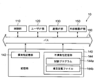
- FIG. 2 is a diagram illustrating a configuration example of the test apparatus 10.
- the test apparatus 10 includes a control unit 110, a user interface (hereinafter abbreviated as “I / F”) unit 120, a communication I / F unit 130, a storage unit 140, and an external device I / F unit 150. And a bus 160 that mediates data exchange between these components.
- I / F user interface
- the control unit 110 is, for example, a CPU (Central Processing Unit).
- the control unit 110 functions as a control center of the test apparatus 10 by executing the test program 144a stored in the storage unit 140 (more precisely, the nonvolatile storage unit 144). Details of processing executed by the control unit 110 in accordance with the test program 144a will be clarified later.
- the user I / F unit 120 includes a display unit and an operation unit (both not shown in FIG. 2).
- the display unit is composed of a display device such as a liquid crystal display and its drive circuit. Various screens for testing the drive device 20 are displayed on the display unit under the control of the control unit 110.
- the operation unit includes a pointing device such as a mouse and a keyboard. The operation unit is for causing the tester to perform various input operations for performing the test of the drive device 20, and the control unit 110 stores data corresponding to the content of the operation performed on the pointing device or the like. To give. As a result, the operation content of the person in charge of the test is transmitted to the control unit 110.
- the communication I / F unit 130 is, for example, a NIC (Network Interface Card), and is connected to the driving device 20 via a signal line.
- the communication I / F unit 130 provides the data received from the drive device 20 via the signal line to the control unit 110, and transmits the data provided from the control unit 110 to the drive device 20 via the signal line.
- the external device I / F unit 150 is a collection of interfaces for connecting other devices to the test apparatus 10 such as a USB interface and a parallel interface.
- the storage unit 140 includes a volatile storage unit 142 and a nonvolatile storage unit 144 as shown in FIG.
- the volatile storage unit 142 is configured by a volatile memory such as a RAM (Random Access Memory).
- the volatile storage unit 142 is used by the control unit 110 as a work area when executing the test program 144a.
- the non-volatile storage unit 144 is configured by a non-volatile memory such as a hard disk or a flash memory.
- the nonvolatile storage unit 144 stores a test program 144a and an item definition file 144b in advance.
- OS software that implements an OS (Operating System) is also stored in the nonvolatile storage unit 144, but is not shown because it is not related to the present invention. did.
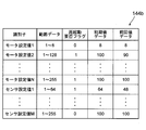
- FIG. 3 is a diagram showing an example of the contents of the item definition file 144b.
- range data In the item definition file 144b, range data, a restart necessity flag, initial value data, and previous value data are written in association with an identifier that uniquely indicates each item whose value is stored in the storage unit of the driving device 20. Yes.
- An example of the identifier is a character string that represents the name of the item.
- the range data is data indicating a range of possible values of the item indicated by the identifier associated with the range data.
- the restart necessity flag is a flag indicating whether or not the drive device 20 needs to be restarted when the value of the item indicated by the identifier associated with the restart necessity flag is updated (if restart is necessary, “ 1 ”is a flag that is set to“ 0 ”if there is no need for restart).
- the initial value data is data representing an initial setting value at the time of factory shipment of the drive device 20 for the item indicated by the identifier associated with the initial value data.
- the previous value data is data indicating a value set in the previous test with respect to the item indicated by the identifier associated with the previous value data. When the test of the drive device 20 is performed for the first time by the test apparatus 10, the same data as the initial value data is set in the previous value data.
- the item definition file 144b shown in FIG. 3 includes motor setting value 1 to motor setting value N (N is an arbitrary natural number) and sensor setting value 1 to sensor setting value M as items to be set in the drive device 20.
- N is an arbitrary natural number
- M is an arbitrary natural number
- the motor setting value 1 to the motor setting value N are items according to the specifications of the electric motor 30, and the sensor setting value 1 to the sensor setting value M are items according to the specifications of the sensor for detecting the driving state of the electric motor 30.
- the range of values that can be taken is 1 to 8, and even if the value of the item is changed, it is not necessary to restart the drive device 20.
- the item definition file 144b is paired with the drive device to be tested (the drive device 20 in this embodiment), and is provided by the manufacturer of the drive device 20 together with the test program 144a.
- the recording medium (for example, the test program 144a and the item definition file 144b is stored from the provider of the driving device 20 to the delivery destination of the driving device 20 (for example, the manufacturer of the EV in which the driving device 20 is mounted). USB memory).
- the recording medium is connected to the external device I / F unit 150 of a personal computer (personal computer having each unit shown in FIG. 2) used as the test device 10. Then, the personal computer can be used as the test apparatus 10 by reading the test program 144a and the item definition file 144b from the recording medium and storing them in the non-volatile storage unit 144 of the personal computer.
- the control unit 110 reads the OS software from the non-volatile storage unit 144 to the volatile storage unit 142 when power to the test apparatus 10 (not shown) is turned on, and starts its execution. In this state, when an execution instruction for the test program 144a is given via the operation unit of the user I / F unit 120, the control unit 110 reads the test program 144a from the nonvolatile storage unit 144 to the volatile storage unit 142, Start its execution.
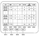
- the control unit 110 that has started the execution of the test program 144a first reads the item definition file 144b from the nonvolatile storage unit 144, and displays a setting value adjustment support screen (see FIG. 4) according to the contents of the item definition file 144b. At this time, the control unit 110 sets each identifier stored in the item definition file 144b in the name field G010 of the setting value adjustment support screen, sets the value range represented by the same range data in the range field G020, The value represented by the value data is set in the factory initial value column G030, and the value represented by the previous value data is set in the previous value column G040.
- the reset column G050 of the set value adjustment support screen is a display item for notifying the testing staff of whether or not the drive device 20 needs to be restarted when the set value is updated.
- the control unit 110 uses a predetermined mark (in this embodiment, for informing the test person that the restart is necessary in the reset column G050 for items whose restart flag value is “1”. #) Is set. Note that the setting value input / output field G060 and the change field G070 are blank immediately after the start of the display of the setting value adjustment support screen shown in FIG. 4, and values and the like are displayed when the READ button B010 described later is pressed. .
- the person in charge of the test who visually recognizes the setting value adjustment support screen sets N + M items as motor setting value 1 to motor setting value N and sensor setting value 1 to sensor setting value M as items to be set in the driving device 20. It is possible to grasp that there is, and avoid setting omission of the value. Further, in the present embodiment, since the range of values that can be taken for each item is displayed for each item, it is possible to prevent accidental rewriting to a value outside the range. Further, an item that needs to be restarted when the value is changed (in the example shown in FIG. 4, the motor setting value 2, the motor setting value N, and the sensor setting value 1) is a predetermined mark (in this embodiment, “#”). Therefore, it is possible to prevent forgetting to restart due to a change in the value of the item. *
- the set value adjustment support screen is provided with four types of virtual operators: a READ button B010, a WRITE button B020, an initialization button B030, and a SAVE button B040.
- the roles of these virtual operators are as follows.
- the READ button B010 is a virtual operator that allows the tester to input read instructions for various setting values stored in the drive device to be tested.
- the control unit 110 detects the pressing of the READ button B010 with reference to the operation content data given from the user I / F unit 120 (for other virtual operators). The same).
- the control unit 110 that detects the pressing of the READ button B010 communicates with the connection-destination driving device 20 via the communication I / F unit 130, and acquires the setting values of each item stored in the driving device 20.
- the control unit 110 displays each set value acquired in this way in the set value input / output column G060 of the item corresponding to the set value.
- the set value input / output field G060 can be rewritten by operating the operation unit of the user I / F unit 120, and the person in charge of the test can freely rewrite the value of the set value input / output field G060. it can.
- the control unit 110 compares the setting value acquired from the drive device 20 in the above manner with the initial setting value corresponding to the setting value, and for items that are different from each other, the initial setting at the time of factory shipment is compared.
- a predetermined mark in this embodiment, “*” that calls attention to the fact that the value is different from the value is displayed in the change column G070.
- the motor setting value 2, the motor setting value N, and the sensor setting value 1 are illustrated as values different from the initial setting values. Since the “*” is displayed in the change column G070 of these items, the person in charge of the test can grasp at a glance that the values set in these items are different from the initial setting values at the time of shipment from the factory. . In addition, in the present embodiment, the initial setting values at the time of shipment from the factory for each item are also displayed, so it is easy to see how much the value set at the present time (or the value to be set in the future) differs from the initial setting value. I can grasp it.
- the WRITE button B020 is a virtual operation element for causing the test person to input a setting value writing instruction for storing the setting value displayed in the setting value input / output field G060 in the driving apparatus to be tested.
- the control unit 110 that has detected the pressing of the WRITE button B020 transmits each setting value displayed in the setting value input / output field G060 and an identifier corresponding to the setting value via the communication I / F unit 130.
- the setting value is stored as the value of the item indicated by the identifier. Therefore, the person in charge of the test causes the drive device 20 to store each setting value input to the setting value adjustment support screen by pressing the WRITE button B020 after rewriting the value in each setting value input / output field G060. Can do.
- the initialization button B030 is a virtual operation element for causing the tester to input an initialization instruction for instructing to write back various setting values stored in the drive device to be tested to the factory-set initial setting values. is there.
- the control unit 110 that has detected the pressing of the initialization button B030 transmits the initial value data and the identifier stored in the item definition file 144b to the connected drive device 20 via the communication I / F unit 130.
- the setting value changed with the execution of the test of the driving device 20 can be easily returned to the initial value at the time of shipment from the factory, which is convenient. improves.
- the SAVE button B040 is a virtual operator for causing the test person to input a setting value saving instruction for writing each setting value displayed in the setting value input / output field G060 of the setting value adjustment support screen to the item definition file 144b. .
- the control unit 110 that has detected the pressing of the SAVE button B040 updates the previous value data stored in the item definition file 144b with the setting value displayed in the setting value input / output field G060 corresponding to the previous value data.
- test apparatus 10 of the above embodiment has the user I / F unit 120 including the display unit and the operation unit, the user I / F unit 120 is omitted and is connected to the test apparatus 10 respectively.
- the user I / F unit 120 may serve as a display device, a keyboard, and the like.
- items for which values are set in the drive device 20 correspond to the specifications of the motor 30 (motor setting value 1 to motor setting value N) and sensors for detecting the driving state of the motor 30.
- items whose values are set in the driving device 20 may include items depending on both the specifications of the electric motor 30 and the specifications of the sensor.
- the setting value adjustment support screen is displayed with the setting value input / output field G060 and the change field G070 blank, and then triggered by pressing the READ button B010.
- the case where the setting values of the respective items are acquired from the driving device 20 and the display control of the setting value input / output column G060 and the change column G070 is performed has been described.
- a setting value adjustment support screen having only the READ button B010 is displayed, and when the READ button B010 is pressed, the value of each item is obtained from the drive device 20 and the above-mentioned fields It is also possible to display a setting value adjustment support screen in which a value is set in the setting value adjustment support screen provided with a virtual operator other than the READ button B010.
- the item whose value has been changed from the initial setting value is notified by the presence / absence of a mark displayed in the change column G070.
- the notification is performed by a voice or the like that reads the identifier of the corresponding item. good. The same applies to notification of items that require a restart when the value is changed.
- the range data, the restart necessity flag, the initial value data, and the data indicating the items to be set for the test target drive device 20 are associated with the identifiers.
- the previous value data was written. However, when it is sufficient to notify the person in charge of the test of only the range of values for each item, only the range data may be associated with the identifier. Similarly, when it is sufficient to notify only the necessity of restart due to a change in value, it is sufficient to associate only the restart necessity flag with the identifier, and the notification of the initial setting value (or the initial setting value) If it is necessary only to specify whether or not there is a change, only the initial value data needs to be associated with the identifier. If only the previous value notification is required, only the previous value data may be associated with the identifier.
- the item definition file 144b corresponding to the drive device 20 to be tested (or the electric motor 30 connected to the drive device 20) is stored in advance in the nonvolatile storage unit 144 of the test device 10.
- the item definition file 144b for the own device (or the electric motor 30 connected to the own device) is stored in the storage unit of the drive device 20, and the item is transferred from the drive device 20 to the test device 10 prior to the start of the test.
- the definition file 144b may be transmitted and stored. Generally, if there is a mismatch between the item definition file 144b stored in the test apparatus 10 and the drive apparatus 20 connected to the test apparatus 10, the test cannot be performed correctly. This is because such inconsistency can be avoided.
- each of the plurality of item definition files includes an identifier indicating a paired driving device (an identifier indicating a model of the driving device such as a character string indicating a model number, or an individual driving device such as a character string indicating a manufacturing number). (Individual identifier shown) is stored in the nonvolatile storage unit 144 in association with each other.
- control unit 110 acquires the identifier of the driving device from the driving device to be tested immediately after the start of the execution of the test program 144a, and the item definition file stored in the nonvolatile storage unit 144 in association with the identifier. Accordingly, the setting value adjustment support screen may be displayed.
- test program 144a and the item definition file 144b of the above embodiment may be distributed by downloading via a telecommunication line such as the Internet. This is because by operating a general computer according to the program distributed in this way, the computer can function as the test apparatus 10 of the present embodiment.
Landscapes
- Engineering & Computer Science (AREA)
- Power Engineering (AREA)
- Physics & Mathematics (AREA)
- General Physics & Mathematics (AREA)
- Control Of Electric Motors In General (AREA)
Abstract
La présente invention permet de rendre plus efficace ou commode un test effectué sur un dispositif d'entraînement tout en empêchant une erreur humaine de se produire pendant, par exemple, une double vérification de l'entrée utilisateur ou du comportement du dispositif. À cet effet, ledit dispositif de test de dispositif d'entraînement est pourvu d'une unité d'interface de communication, d'une unité de stockage, et d'une unité de commande, comme suit. Le dispositif d'entraînement en cours de test est connecté à l''interface de communication. Ledit dispositif d'entraînement est réglé à l'avance sur une valeur pour chaque catégorie d'un certain nombre de catégories déterminées en fonction, par exemple, des spécifications d'un moteur électrique en cours d'entraînement. Un fichier de définition de catégories est stocké au préalable dans l'unité de stockage, et pour chacune des catégories susmentionnées, ledit fichier de définition de catégories contient un réglage initial par défaut de valeurs d'usine pour le dispositif d'entraînement pour cette catégorie en association avec un identifiant qui indique de manière unique cette catégorie. Au moyen d'une communication par l'intermédiaire de l'unité d'interface de communication, l'unité de commande acquiert des valeurs par catégorie sur lesquelles le dispositif d'entraînement a été réglé. L'unité de commande lit également les réglages initiaux pour les catégories correspondant auxdites valeurs à partir du fichier de définition de catégories et affiche les deux, conjointement avec les identifiants qui indiquent lesdites catégories, sur un dispositif d'affichage.
Priority Applications (1)
| Application Number | Priority Date | Filing Date | Title |
|---|---|---|---|
| PCT/JP2014/070185 WO2016016992A1 (fr) | 2014-07-31 | 2014-07-31 | Dispositif de test pour tester un dispositif d'entraînement qui effectue une commande d'entraînement sur un moteur électrique |
Applications Claiming Priority (1)
| Application Number | Priority Date | Filing Date | Title |
|---|---|---|---|
| PCT/JP2014/070185 WO2016016992A1 (fr) | 2014-07-31 | 2014-07-31 | Dispositif de test pour tester un dispositif d'entraînement qui effectue une commande d'entraînement sur un moteur électrique |
Publications (1)
| Publication Number | Publication Date |
|---|---|
| WO2016016992A1 true WO2016016992A1 (fr) | 2016-02-04 |
Family
ID=55216933
Family Applications (1)
| Application Number | Title | Priority Date | Filing Date |
|---|---|---|---|
| PCT/JP2014/070185 Ceased WO2016016992A1 (fr) | 2014-07-31 | 2014-07-31 | Dispositif de test pour tester un dispositif d'entraînement qui effectue une commande d'entraînement sur un moteur électrique |
Country Status (1)
| Country | Link |
|---|---|
| WO (1) | WO2016016992A1 (fr) |
Cited By (1)
| Publication number | Priority date | Publication date | Assignee | Title |
|---|---|---|---|---|
| CN105738741A (zh) * | 2016-04-05 | 2016-07-06 | 常胜 | 一种交流充电桩功能测试装置 |
Citations (4)
| Publication number | Priority date | Publication date | Assignee | Title |
|---|---|---|---|---|
| JP2002099324A (ja) * | 2000-09-26 | 2002-04-05 | Yamatake Sangyo Systems Co Ltd | 作業工程管理システム |
| JP2002223585A (ja) * | 2001-01-26 | 2002-08-09 | Keyence Corp | 電動機駆動装置の制御パラメータ設定支援方法及び装置 |
| JP2005006450A (ja) * | 2003-06-13 | 2005-01-06 | Yaskawa Electric Corp | モータ制御装置のパラメータ変更履歴表示方法 |
| JP2014039772A (ja) * | 2012-08-24 | 2014-03-06 | Suzuki Motor Corp | 電動車いすの制御装置 |
-
2014
- 2014-07-31 WO PCT/JP2014/070185 patent/WO2016016992A1/fr not_active Ceased
Patent Citations (4)
| Publication number | Priority date | Publication date | Assignee | Title |
|---|---|---|---|---|
| JP2002099324A (ja) * | 2000-09-26 | 2002-04-05 | Yamatake Sangyo Systems Co Ltd | 作業工程管理システム |
| JP2002223585A (ja) * | 2001-01-26 | 2002-08-09 | Keyence Corp | 電動機駆動装置の制御パラメータ設定支援方法及び装置 |
| JP2005006450A (ja) * | 2003-06-13 | 2005-01-06 | Yaskawa Electric Corp | モータ制御装置のパラメータ変更履歴表示方法 |
| JP2014039772A (ja) * | 2012-08-24 | 2014-03-06 | Suzuki Motor Corp | 電動車いすの制御装置 |
Cited By (1)
| Publication number | Priority date | Publication date | Assignee | Title |
|---|---|---|---|---|
| CN105738741A (zh) * | 2016-04-05 | 2016-07-06 | 常胜 | 一种交流充电桩功能测试装置 |
Similar Documents
| Publication | Publication Date | Title |
|---|---|---|
| CN103314359B (zh) | 用于更新固件的系统和方法 | |
| CN106030426B (zh) | 绘图装置以及控制系统 | |
| US10833924B2 (en) | Data collecting apparatus, data collecting method, and program | |
| US20170146602A1 (en) | System and Method for Testing Alternator Default Mode Operation | |
| CN105027425B (zh) | 控制装置和映射文件变换装置 | |
| JP5971410B2 (ja) | 制御装置および電動機の駆動装置 | |
| WO2018043107A1 (fr) | Dispositif de mise à jour embarqué et système de mise à jour de embarqué | |
| CN116846790A (zh) | 一种服务器异常监控方法、装置、设备及存储介质 | |
| CN105051701A (zh) | 设计工具 | |
| WO2016016992A1 (fr) | Dispositif de test pour tester un dispositif d'entraînement qui effectue une commande d'entraînement sur un moteur électrique | |
| EP3101537A1 (fr) | Dispositif de commande, système de commande, procédé de commande pour dispositif de commande et procédé de commande pour système de commande | |
| WO2016016993A1 (fr) | Dispositif de test pour tester un dispositif d'entraînement qui effectue une commande d'entraînement sur un moteur électrique | |
| JP6222369B2 (ja) | 電動機の駆動制御を行う駆動装置の試験を行うための試験装置 | |
| US10108187B2 (en) | Control device, control system, support device, and control-device maintenance management method | |
| CN107943500A (zh) | 一种组合仪表软件更新方法 | |
| JP6253846B1 (ja) | プログラマブル表示器 | |
| US20210303495A1 (en) | Setting assistance device, setting assistance method, and program | |
| CN118017898A (zh) | 一种电机零位角标定方法、车辆和存储介质 | |
| CN103176857A (zh) | 具有固件更新功能的系统、电子装置及其固件更新方法 | |
| US20170236496A1 (en) | Vehicular display device | |
| JP6695517B1 (ja) | プログラマブル表示器およびデータ管理方法 | |
| US20200144953A1 (en) | Brushless dc motor with automatic record of abnormal operation and method therefor | |
| JP6572762B2 (ja) | 電子機器、方法、およびプログラム | |
| CN115229799B (zh) | 机器人的位置确定方法、确定装置以及机器人系统 | |
| JP4951749B2 (ja) | コンピュータ装置 |
Legal Events
| Date | Code | Title | Description |
|---|---|---|---|
| 121 | Ep: the epo has been informed by wipo that ep was designated in this application |
Ref document number: 14898466 Country of ref document: EP Kind code of ref document: A1 |
|
| NENP | Non-entry into the national phase |
Ref country code: DE |
|
| NENP | Non-entry into the national phase |
Ref country code: JP |
|
| 122 | Ep: pct application non-entry in european phase |
Ref document number: 14898466 Country of ref document: EP Kind code of ref document: A1 |