WO2016017031A1 - Structure de porte destinée à un panneau d'équipement - Google Patents
Structure de porte destinée à un panneau d'équipement Download PDFInfo
- Publication number
- WO2016017031A1 WO2016017031A1 PCT/JP2014/070365 JP2014070365W WO2016017031A1 WO 2016017031 A1 WO2016017031 A1 WO 2016017031A1 JP 2014070365 W JP2014070365 W JP 2014070365W WO 2016017031 A1 WO2016017031 A1 WO 2016017031A1
- Authority
- WO
- WIPO (PCT)
- Prior art keywords
- door
- handle
- setting
- suspension member
- sliding rod
- Prior art date
- Legal status (The legal status is an assumption and is not a legal conclusion. Google has not performed a legal analysis and makes no representation as to the accuracy of the status listed.)
- Ceased
Links
Images






Classifications
-
- H—ELECTRICITY
- H02—GENERATION; CONVERSION OR DISTRIBUTION OF ELECTRIC POWER
- H02B—BOARDS, SUBSTATIONS OR SWITCHING ARRANGEMENTS FOR THE SUPPLY OR DISTRIBUTION OF ELECTRIC POWER
- H02B1/00—Frameworks, boards, panels, desks, casings; Details of substations or switching arrangements
- H02B1/26—Casings; Parts thereof or accessories therefor
- H02B1/30—Cabinet-type casings; Parts thereof or accessories therefor
- H02B1/38—Hinged covers or doors
-
- E—FIXED CONSTRUCTIONS
- E05—LOCKS; KEYS; WINDOW OR DOOR FITTINGS; SAFES
- E05B—LOCKS; ACCESSORIES THEREFOR; HANDCUFFS
- E05B63/00—Locks or fastenings with special structural characteristics
- E05B63/14—Arrangement of several locks or locks with several bolts, e.g. arranged one behind the other
-
- E—FIXED CONSTRUCTIONS
- E05—LOCKS; KEYS; WINDOW OR DOOR FITTINGS; SAFES
- E05B—LOCKS; ACCESSORIES THEREFOR; HANDCUFFS
- E05B65/00—Locks or fastenings for special use
-
- H—ELECTRICITY
- H02—GENERATION; CONVERSION OR DISTRIBUTION OF ELECTRIC POWER
- H02B—BOARDS, SUBSTATIONS OR SWITCHING ARRANGEMENTS FOR THE SUPPLY OR DISTRIBUTION OF ELECTRIC POWER
- H02B1/00—Frameworks, boards, panels, desks, casings; Details of substations or switching arrangements
- H02B1/26—Casings; Parts thereof or accessories therefor
- H02B1/30—Cabinet-type casings; Parts thereof or accessories therefor
-
- H—ELECTRICITY
- H05—ELECTRIC TECHNIQUES NOT OTHERWISE PROVIDED FOR
- H05K—PRINTED CIRCUITS; CASINGS OR CONSTRUCTIONAL DETAILS OF ELECTRIC APPARATUS; MANUFACTURE OF ASSEMBLAGES OF ELECTRICAL COMPONENTS
- H05K5/00—Casings, cabinets or drawers for electric apparatus
- H05K5/02—Details
- H05K5/03—Covers
Definitions
- the present invention relates to a door structure of an equipment panel of an industrial machine.
- JP 2005-188158 A Japanese Utility Model Publication No. 63-121482
- Some of the above-described equipment panels include a master door that is opened when a breaker or the like is operated and a sub-door that is opened when other equipment is operated.
- a master door that is opened when a breaker or the like is operated
- a sub-door that is opened when other equipment is operated.
- the breaker when the breaker is ON, other devices are also energized. Therefore, it is desirable to lock the sub door in addition to the master door so that it cannot be operated by the operator.
- the sub door instead of locking the sub door in conjunction with opening and closing of the master door, it may be desirable to lock the sub door according to the setting of the switch inside the device panel or the operating state of the device inside the device panel. is there. For example, it is desirable that the sub door is locked when the breaker of the equipment panel is ON.
- An object of the present invention is to provide a door structure of an equipment panel in which the sub door is locked in accordance with the setting or operation of the equipment panel in addition to the operation of the sub door handle.
- a door structure is a door structure for an industrial machine equipment panel, and includes a first door, a handle, a locking bar, a suspension member, a sliding rod, a handle catch, and a rod drive.
- a mechanism and a first setting member are provided.
- the handle is rotatably provided on the first door.
- the locking bar is installed on the first door.
- the locking bar moves up and down according to the rotation of the handle, and locks or unlocks the first door.
- the suspension member is suspended above the locking bar so as to be swingable in the front-rear direction.
- the sliding rod is rod-shaped.
- the handle catch is fixed at a predetermined position in the axial direction of the sliding rod. Handle catches protrude from the sliding rod.
- the handle catch includes an upper surface for contacting the bottom surface of the suspension member.
- the rod drive mechanism moves the sliding rod in the axial direction of the sliding rod. Whether the first setting or the second setting is performed by the rod driving mechanism can be set by the first setting member. In the first setting, the rod drive mechanism moves the sliding rod so that the bottom surface of the suspension member and the top surface of the handle catch overlap each other when viewed from above. In the second setting, the rod drive mechanism moves the sliding rod so that the bottom surface of the suspension member and the top surface of the handle catch do not overlap in top view.
- the suspension member is positioned above the upper surface of the handle catch. After the first door is locked and the first setting is made in the rod drive mechanism, when the handle is rotated in the direction in which the first door is unlocked, the bottom surface of the suspension member is The rotation of the handle is prevented by contacting the upper surface.
- the suspension member may further include a first sliding surface for sliding with the first end of the handle catch.
- first sliding surface for sliding with the first end of the handle catch.
- the door structure may further include a second setting member and an external force applying member. Whether or not to cancel the first setting by the rod driving mechanism may be set by the second setting member.
- the external force applying member is set to release the first setting by the second setting member, an external force other than gravity is applied to the suspension member, and the bottom surface of the suspension member and the handle catch are not overlapped in top view.
- the hanging member may be rotated.
- the suspension member may be further swingable in the left-right direction.
- the hanging member may further include a second sliding surface.
- the second sliding surface may be opposed to the second end portion of the handle catch in a state where the second setting is made in the rod drive mechanism.
- the door structure may further include a second door different from the first door.
- the first setting member may be a second door.
- the first setting may be a setting that locks the first door in conjunction with closing the second door.
- the second setting may be a setting for unlocking the first door in conjunction with opening the second door.
- the rod drive mechanism may include a roller, a sliding rod guide, and a first pressing mechanism.
- the roller may be provided at the tip of the sliding rod.
- the sliding rod guide may be provided behind the second door and include a curved contact surface that contacts the roller.
- the first pressing mechanism may press the sliding rod roller against the sliding rod guide.
- the first setting member may be an external operation handle for setting the breaker ON or OFF.
- the first setting may be performed by the rod driving mechanism.
- the first setting may be a setting that locks the first door in conjunction with the ON state of the breaker.
- the second setting may be a setting for unlocking the first door in conjunction with the OFF state of the breaker.
- the door structure may further include a second door different from the first door.
- the external operation handle may be positioned inside the outer shape of the second door in front view.
- the rod drive mechanism may further include a first wire, a second wire, a wire casing, a link mechanism, and a second pressing mechanism.
- the first wire may be connected to the tip of the sliding rod.
- the second wire may be connected to the external operation handle.
- the wire casing may be fixed inside the equipment panel.
- the second wire may slide inside the wire casing.
- the link mechanism may be connected to the first wire and the second wire together.
- the second pressing mechanism may press the sliding rod in a direction away from the link mechanism in the axial direction described above.
- the door structure may include a plurality of first doors.
- Each of the plurality of first doors may be provided with a handle, a locking bar, a suspension member, a second setting member, and an external force applying member separately.
- a handle catch corresponding to each of the suspension members may be fixed to the sliding rod.
- the door structure may further include a third door adjacent to the first door. If the first door is not opened, the first door may be prevented from opening the third door.
- the sliding rod is preferably arranged in the horizontal direction.
- the suspension member may be triangular.
- the bottom surface of the suspension member may be a horizontal plane.
- the upper surface of the handle catch may be a horizontal plane.
- the external force applying member may include a handle release bar, a release lever, and a release lever support member.
- the handle release bar may be raised and lowered according to the setting of the second setting member.
- the release lever may be rotatably connected to the upper end portion of the handle release bar.
- the release lever may be L-shaped.
- the release lever support member may be fixed to the first door.
- the release lever support member may support the release lever rotatably.
- the hanging member may include a protrusion protruding in at least one of the left and right directions from the side surface of the hanging member. When the handle release bar rises, the release lever may hook the protrusion and rotate the suspension member forward.
- the rear end of the protrusion is preferably located in front of the first end of the handle catch.
- the second setting member may be a rotatable handle release screw.
- the handle release bar may be raised or lowered according to the rotation of the handle release screw.
- the setting angle of the handle release screw is set to a predetermined first angle, the handle release bar is raised, and the suspension member is preferably rotated to a position where the bottom surface of the suspension member and the handle catch do not overlap in top view.
- the first setting or the second setting is performed is set by the first setting member, and the first setting is performed by the rod driving mechanism.
- the sliding rod moves so that the bottom surface of the suspension member and the top surface of the handle catch overlap each other when viewed from above. Therefore, the door structure of the equipment panel in which the first door (sub door) is locked according to the setting or operation of the equipment panel other than the handle of the first door (sub door) is realized.
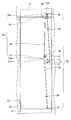
- FIG. 1 is a front view of an equipment panel 1 according to the first embodiment of the present invention.
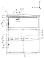
- FIG. 2 is a cross-sectional view of the equipment panel 1 as seen from the section line II-II in FIG.
- the equipment panel 1 may be anything as long as it is used as an equipment board for an industrial machine, and includes, for example, a distribution board, a distribution board, an industrial machine control board, and the like.
- the equipment panel 1 includes a housing 10, a master door 30, a first sub door 20, and a second sub door 26. As shown in FIG. 2, the equipment panel 1 includes a breaker 90 and control devices 98 and 99 inside the housing 10.
- the control devices 98 and 99 may be power distribution devices or power distribution devices.
- the front direction is a direction perpendicular to the back surface 19 (see FIG. 2) of the housing 10 and is directed from the back surface 19 to the first sub door 20 (or the master door 30 and the second sub door 26).
- the rear direction is a direction from the first sub door 20 (or the master door 30 and the second sub door 26) toward the back surface 19.
- the forward direction is shown as the positive direction of the x axis
- the backward direction is shown as the negative direction of the x axis.
- the vertical direction and the horizontal direction viewed from the person standing on the floor where the equipment panel 1 is installed with the face facing forward are defined as the vertical direction and the horizontal direction respectively. To do.
- the upward direction is shown as the positive direction of the y-axis
- the downward direction is shown as the negative direction of the y-axis
- the left direction is shown as the positive direction of the z axis
- the right direction is shown as the negative direction of the z axis.
- the master door 30, the first sub door 20, and the second sub door 26 are arranged side by side. In the drawing, an example in which the master door 30, the first sub door 20, and the second sub door 26 are arranged in order from the left is shown. In the following description, the first sub door 20, the master door 30, and the second sub door 26 may be referred to as a first door, a second door, and a third door, respectively.
- the housing 10 includes a first upper flange 11, a first lower flange 12, a second upper flange 13, and a second lower flange 14.
- the first upper flange 11 and the second upper flange 13 are surfaces that protrude downward from the ceiling of the housing 10.
- the first lower flange 12 and the second lower flange 14 are surfaces that protrude upward from the bottom surface of the housing 10.
- the first upper flange 11 and the first lower flange 12 face the first sub door 20 when the first sub door 20 is closed, and overlap the first sub door 20 in a front view.
- the second upper flange 13 and the second lower flange 14 face the master door 30 when the master door 30 is closed, and overlap the master door 30 in a front view.
- the first handle 21 and the first door hinge 23 are provided on the first sub door 20.
- the first sub door 20 is rotated by the first door hinge 23.
- the first sub door 20 is locked or unlocked by the rotation of the first handle 21.
- the first handle 21 is provided with a handle extending in the radial direction of the rotation shaft of the first handle 21 so that the first handle can be easily rotated by the operator's hand.
- the first sub door 20 is provided with a sub door lock mechanism 50.
- FIG. 3 is a rear view of the first sub door 20.
- the sub door lock mechanism 50 includes a first crank arm 51, a first locking bar 52, a second locking bar 53, a first bar guide 54, a second bar guard 55, a first roller 56, 2 rollers 57 are included.
- a flat plate-like first crank arm 51 is attached to the handle shaft 21 a of the first handle 21.
- a first locking bar 52 extending upward and a second locking bar 53 extending downward are attached to both ends of the first crank arm 51. That is, the first locking bar 52 and the second locking bar 53 are installed on the first sub door 20.
- the first locking bar 52 is rotatably attached to the first crank arm 51 via a joint J1.
- the first locking bar 52 is preferably a rod-shaped member.
- the first locking bar 52 is supported by the first bar guide 54.
- the first locking bar 52 moves up and down in accordance with the rotation of the first handle 21 (first crank arm 51). Specifically, when the first sub door 20 is locked by the first handle 21, the first locking bar 52 rises.
- the first locking bar 52 is lowered.
- a first roller 56 is provided at the upper end of the first locking bar 52. The first roller 56 moves up and down as the first locking bar 52 moves up and down.
- FIG. 4 shows a state in which the first sub door 20 is unlocked by the first handle 21.
- the first roller 56 is positioned below the first upper flange 11 of the housing 10. For this reason, when the 1st subdoor 20 is unlocked by the 1st handle 21, since the 1st roller 56 does not catch on the rear surface of the 1st upper flange 11 of case 10, an operator opens the 1st subdoor 20. Can do.
- the second rocking bar 53 is rotatably attached to the first crank arm 51 via the joint J2.
- the second locking bar 53 is preferably a rod-shaped member.
- the second locking bar 53 is supported by the second bar guide 55.
- the second locking bar 53 moves up and down in accordance with the rotation of the first handle 21 (first crank arm 51). Specifically, when the first sub door 20 is locked by the first handle 21, the second locking bar 53 is lowered. When the first sub door 20 is unlocked by the first handle 21, the second locking bar 53 is raised.
- a second roller 57 is provided at the lower end of the second locking bar 53. The second roller 57 moves up and down as the second locking bar 53 moves up and down.
- the second roller 57 contacts the rear surface of the first lower flange 12 of the housing 10 (see FIG. 1). Accordingly, when the first sub door 20 is locked by the first handle 21, the second roller 57 is caught on the rear surface of the first lower flange 12 of the housing 10, so that the operator cannot open the first sub door 20. 3 and 4, when the first sub door 20 is unlocked by the first handle 21, the second roller 57 is positioned above the first lower flange 12 of the housing 10. For this reason, when the 1st subdoor 20 is unlocked by the 1st handle 21, since the 2nd roller 57 does not catch on the rear surface of the 1st lower flange 12 of case 10, an operator opens the 1st subdoor 20. Can do.
- the second sub door 26 is disposed adjacent to the first sub door 20.
- the second sub door 26 is also provided with a third door hinge 27, and the second sub door 26 is rotated by the third door hinge 27.
- the left end 28 of the second sub door 26 is located directly behind the right end 24 of the first sub door 20. For this reason, the operator cannot open the second sub door 26 unless the first sub door 20 is opened.
- the master door 30 is also provided with a second handle 31 and a second door hinge 33 in the same manner as the first sub door 20.
- a master door lock mechanism 70 is provided on the back side of the master door 30 opposite to the front side of the master door 30 to which the second handle 31 is attached.
- the master door lock mechanism 70 includes a second crank arm 71, a third locking bar 72, a fourth locking bar 73, a third bar guide 74, a fourth bar guard 75, a third roller 76, and a fourth roller 77.
- Second handle 31, second door hinge 33, second crank arm 71, third locking bar 72, fourth locking bar 73, third bar guide 74, fourth bar guard 75, third roller 76, and fourth roller 77 Are the first handle 21, the first door hinge 23, the first crank arm 51, the first locking bar 52, the second locking bar 53, the first bar guide 54, the second bar guard 55, the first roller 56, and Since it has the same structure and function as the second roller 57, a detailed description is omitted.
- the third roller 76 contacts the rear surface of the second upper flange 13 of the housing 10. Further, when the master door 30 is unlocked by the second handle 31, the third roller 76 is positioned below the second upper flange 13 of the housing 10. Referring to FIG. 1, when the master door 30 is locked by the second handle 31, the fourth roller 77 contacts the rear surface of the second lower flange 14 of the housing 10. Further, when the master door 30 is unlocked by the second handle 31, the fourth roller 77 is positioned above the second lower flange 14 of the housing 10.
- the master door 30 further has an opening 32 so that the external operation handle 92 of the breaker 90 can be operated from the front side of the master door 30. Therefore, the external operation handle 92 is located inside the outer shape of the master door 30 in the front view. 1 and 2, the breaker 90 is attached to a bracket 19 that protrudes forward from the back surface 19 of the housing 10. The breaker 90 is located on the inner side (rear side) of the master door 30.
- FIG. 4 shows the equipment panel in a state where the master door is open. According to this, the breaker 90 includes the external operation handle 92 and the release screw 93 protruding from the breaker body 91 toward the front (master door 30).
- the breaker body 91 has openings in the left-right direction or the front-rear direction.
- An operation handle 96 (details will be described later) of the breaker main body 91 and an external member can be connected.
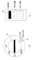
- FIG. 5A is an enlarged view of the external operation handle 92 and the release screw 93 of the breaker 90.
- ON / OFF / TRIP / RESET is designated according to the rotation angle of the external operation handle 92.
- the ON state of the breaker 90 means a state in which electricity is sent to the control devices 98, 99 and the like.
- the breaker 90 is in an OFF state refers to a state in which the power supply of the entire device panel including the breaker 90, such as the control devices 98 and 99, is OFF.
- the state in which the breaker 90 is in the TRIP state refers to a state in which the power to the breaker 90 is turned on but electricity is not sent to the control devices 98, 99 and the like.
- the master door 30 can be opened and closed in addition to the OFF state described above. That is, when the breaker 90 is in the ON / OFF / TRIP state, the master door 30 is doubly locked in addition to the lock by the second handle 31 by the engaging part (not shown) of the breaker 90. However, when the breaker 90 is in the RESET state, the above-described lock of the master door 30 is released, so that the operator can open the master door 30.
- FIG. 5B shows an operation handle 96 provided on the breaker body 91.
- the operation handle 96 moves up and down as shown in the figure in conjunction with the direction of the external operation handle 92. That is, when “OFF” or “RESET” is set by the external operation handle 92, the operation handle 96 points to the lowest “OFF position”. Further, when “ON” is set by the external operation handle 92, the operation handle 96 indicates the uppermost “ON position”. When “TRIP” is set by the external operation handle 92, the operation handle 96 indicates a “TRIP position” located between the “ON position” and the “OFF position”.
- FIG. 5B shows a state where the external operation handle 92 points to the “ON position”.
- the release screw 93 is a member for setting the release of the master door 30 by the breaker 90 by operating the engaging part of the breaker 90 when the breaker 90 is in the ON / OFF / TRIP state.
- the release screw 93 is normally set in the direction of LOCK in FIG.
- the release screw 93 is rotated in the direction of UNLOCK in FIG. 5A, the master door 30 is unlocked by the breaker 90 even if the breaker 90 is in the ON / OFF / TRIP state. That is, the operator can open the master door 30 even when the breaker 90 is in the ON / OFF / TRIP state.
- the release screw 93 is rotated in the direction of LOCK in FIG. 5A, the locking component of the breaker 90 returns to the normal position. That is, when the breaker 90 is in the ON / OFF / TRIP state, the master door 30 is locked by the breaker 90.
- the equipment panel 1 includes an interlock mechanism 80 as its door structure.
- the interlock mechanism 80 locks / unlocks the first sub door 20 in conjunction with opening / closing of the master door 30.
- the interlock mechanism 80 includes the sliding rod 40, the first pressing mechanism 82, the fifth roller 83, the handle catch 49, the sliding rod guide 35, and the suspension member 100.
- the sliding rod 40 is a rod-like member extending in the left-right direction.
- the sliding rod 40 extends from a position behind the master door 30 (position of the fifth roller 83) to a position behind the second sub door 26 (position of a first flange 41 described later).
- the sliding rod 40 is supported by a first support member 16 and a second support member 17 that extend downward from the ceiling of the housing 10. For this reason, the sliding rod 40 is arranged in the horizontal direction.
- the sliding rod 40 includes a first flange 41 and a second flange 42.
- the first pressing mechanism 82 is disposed between the second flange 42 and the second support member 17.
- the first pressing mechanism 82 is typically a spring, but may be any member that can expand and contract, such as rubber.
- the fifth roller 83 is provided at the tip 44 located inside the master door 30 (the rear side when the master door 30 is closed) of the two tips of the sliding rod 40.
- the sliding rod guide 35 is provided above the master door 30 and inside the master door 30. That is, the master door 30 includes a sliding rod guide 35. As shown in FIG. 2, the sliding rod guide 35 includes a curved first contact surface 35 a for contacting the fifth roller 83.
- the first pressing mechanism 82 presses the fifth roller 83 against the sliding rod guide 35 until the master door 30 opens from the closed state to a predetermined angle.
- 1 and 2 show the positions of the fifth roller 83 and the sliding rod 40 and the state of the first pressing mechanism 82 when the master door 30 is closed. At this time, the first pressing mechanism 82 is most contracted.
- FIG. 4 shows the positions of the fifth roller 83 and the sliding rod 40 and the state of the first pressing mechanism 82 in a state where the master door 30 is completely opened. At this time, the fifth roller 83 is not in contact with the sliding rod guide 35, and the first pressing mechanism 82 is extended until the first flange 41 is in contact with the first support member 16.
- the fifth roller 83 moves on the sliding rod guide 35, so that the sliding rod 40 moves in the axial direction of the sliding rod 40.
- the fifth roller 83, the sliding rod guide 35, and the first pressing mechanism 82 that move the sliding rod 40 in the axial direction of the sliding rod 40 are also referred to as a rod driving mechanism.
- the handle catch 49 is fixed to the sliding rod 40. Therefore, the position of the handle catch 49 moves in the left-right direction according to the position of the sliding rod 40 (the position of the fifth roller 83). As shown in FIGS. 1 and 2, the handle catch 49 is located directly below the suspension member 100 when the master door 30 and the first sub door 20 are locked. Further, as shown in FIGS. 3 and 4, the handle catch 49 is not located directly below the suspension member 100 in a state where the master door 30 is opened. However, since the sliding rod 40 moves in the axial direction (horizontal direction) of the sliding rod 40, the vertical relationship between the suspension member 100 and the handle catch 49 does not change if the first sub door 20 is locked.
- the suspension member 100 is positioned above the upper surface 49 a of the handle catch 49.
- the outer shape of the handle catch 49 in a state where the master door 30 is opened is indicated by a one-dot chain line.
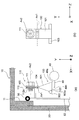
- FIG. 6A shows a shape of the suspension member 100 and the handle catch 49 as viewed from the side (left direction) in a state where the master door 30 and the first sub door 20 are locked.
- FIG.6 (b) has shown the shape which looked at the suspension member 100 from back in the same state as Fig.6 (a).
- the suspension member 100 includes a first sliding surface 101, a bottom surface 102, a protrusion 103, a hinge 104, and an upper support portion 105.
- the hanging member 100 has a substantially triangular shape in a side view. In other words, the suspension member 100 has a substantially triangular prism shape.
- the suspension member 100 is swingable in the front-rear direction by the hinge 104.
- FIG. 1 shows a shape of the suspension member 100 and the handle catch 49 as viewed from the side (left direction) in a state where the master door 30 and the first sub door 20 are locked.
- FIG.6 (b) has shown the shape which looked at the suspension member 100 from back in the same
- the rotation axis of the hinge 104 is indicated by Ax1.
- the suspension member 100 is supported by the shaft support member 110.
- the shaft support member 110 includes an L-shaped third support member 112 fixed to the first locking bar 52 and a bolt 111 screwed into the third support member 112.
- the third support member 112 has a thread groove 112 a corresponding to the thread groove of the bolt 111.
- the upper support portion 105 has an insertion hole through which the bolt 111 is inserted.
- the upper support portion 105 is not fixed by the bolt 111 and is supported by the bolt 111 so as to be swingable in the left-right direction. That is, the suspension member 100 is swingable in the left-right direction.
- the rotation axis when the suspension member 100 swings is indicated by Ax2.
- the third support member 112 is provided near the first roller 56, that is, above the first locking bar 52. Therefore, the suspension member 100 is provided near the first roller 56, that is, above the first locking bar 52.
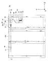
- FIG. 2 shows a view of the suspension member 100 not receiving an external force other than gravity as viewed from above.
- the handle catch 49 shown by a solid line and a dotted line in FIG. 2 is a handle in the state shown in FIG. Shows the catch.
- the rod driving mechanism described above moves the sliding rod 40 so that the bottom surface 102 of the suspension member 100 not receiving external force other than gravity and the upper surface 49a of the handle catch 49 overlap in a top view.
- a setting by the rod driving mechanism is called a first setting or an interlock setting.
- the setting in which the rod drive mechanism moves the handle catch to the position of the handle catch 49 indicated by the one-dot chain line is referred to as a second setting or an interlock-off setting.
- the rod driving mechanism moves the sliding rod 40 so that the bottom surface 102 of the suspension member 100 not receiving an external force other than gravity and the top surface 49a of the handle catch 49 do not overlap in top view.
- Whether the rod drive mechanism performs the first setting (interlock setting) or the second setting (interlock off setting) is determined by opening / closing the master door 30.
- a member capable of setting whether the first setting or the second setting is performed by the rod driving mechanism is referred to as a first setting member. Therefore, in the present embodiment, the first setting member is the master door 30.
- the handle catch 49 includes an upper surface 49a for coming into contact with the bottom surface 102 of the suspension member 100 that is not subjected to an external force other than gravity.
- the bottom surface 102 of the suspension member 100 is preferably a flat surface, and the bottom surface 102 of the suspension member 100 not receiving an external force other than gravity forms a horizontal surface. Therefore, the upper surface 49a of the handle catch 49 is preferably a horizontal plane.
- the shape other than the upper surface 49a of the handle catch 49 may be any shape. From this state (in other words, the state in which the first sub door 20 is locked and the first setting is made by the rod drive mechanism), the first handle 21 is rotated in the direction in which the first sub door 20 is unlocked. When the suspension member 100 does not receive an external force other than gravity, the bottom surface 102 of the suspension member 100 comes into contact with the upper surface 49 a of the handle catch 49. Thereby, the rotation of the first handle 21 is prevented.
- the first sliding surface 101 is a surface for sliding with the first end portion 49b of the handle catch 49.
- the first end 49b is preferably the front end of the handle catch 49.
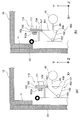
- FIG. 7A shows the state of the suspension member 100 and the handle catch 49 immediately after the first sub door 20 is closed in the state where the master door 30 is closed (that is, the state where the first setting is made in the rod drive mechanism). Indicates the state. That is, in the state shown in FIG. 7A, the first sub door 20 is unlocked.
- the first sliding surface 101 is in contact with the first end 49b of the handle catch 49, and the suspension member 100 is inclined in the front-rear direction. More specifically, the suspension member 100 is inclined in the direction opposite to the handle catch 49 (forward direction).
- FIG. 7B shows a state of the suspension member 100 and the handle catch 49 after the first handle 21 is slightly rotated from the state of FIG. 7A in the direction in which the first sub door 20 is locked. Since the first sliding surface 101 is a flat surface as shown in FIG. 6, the first end 49 b slides with the first sliding surface 101 facing downward without being caught in the middle of the first sliding surface 101. It is moving. When the first sub door 20 is locked, the first end portion 49b is disengaged from the first sliding surface 101, and the suspension member 100 is rotated rearward as shown in FIG. As described above, when the first handle 21 is to be rotated in the direction in which the first sub door is locked after the first sub door 20 is unlocked, the first sliding surface 101 of the suspension member 100 is moved to the handle catch 49. The suspending member 100 is raised while sliding with the first end portion 49b.
- the suspension member 100 preferably further includes a second sliding surface 106.
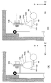
- FIG. 8A shows a state in which the master door 30 is opened (a state in which the second setting (interlock-off setting) is set in the rod drive mechanism), and the suspension member 100 immediately after the first sub door 20 is closed.
- the state of the handle catch 49 is shown.
- Fig.8 (a) is the figure which looked at the suspension member 100 and the handle catch 49 from the front.
- the first sub door 20 is unlocked.
- the second sliding surface 106 faces the second end portion 49c of the handle catch 49 in a state where the second setting is made in the rod driving mechanism.
- the second end portion 49 c is an end portion of the left and right ends of the handle catch 49 that faces the suspension member 100 in a state where the second setting is made in the rod drive mechanism.
- the second end 49c is, for example, the right end of the handle catch 49.
- FIG. 8B shows the suspension member 100 and the handle catch when the master door 30 is closed (when the first setting is made in the rod drive mechanism) with the first sub door 20 closed in an unlocked state. 49 states are shown.
- FIG. 8B is also a view of the suspension member 100 and the handle catch 49 as seen from the front. As shown in FIG. 7A, the handle catch 49 is lower than the hinge 104 even when the first sub door 20 is unlocked. Therefore, when the first setting is made in the rod drive mechanism after the first sub door is closed while being unlocked in the state where the second setting is made in the rod drive mechanism, the handle catch 49 is moved to the second slide. Abuts against the moving surface 106.
- the suspension member 100 since the suspension member 100 is swingable also in the left-right direction, the suspension member 100 is inclined in the left-right direction. More specifically, the suspension member 100 is inclined in the direction opposite to the handle catch 49 (right direction).
- the rotation axis Ax2 rises vertically upward. That is, the suspension member 100 is lifted so that the normal line of the bottom surface 102 gradually approaches vertically downward while the second sliding surface 106 slides with the second end portion 49c.
- the suspension member 100 includes a protrusion 103 that protrudes from the side surface of the suspension member 100 in at least one of the left and right directions.
- the protrusion 103 is provided at least on the first side.
- the rear end 103 a of the protrusion 103 is positioned in front of the first end portion 49 b of the handle catch 49. Therefore, when the suspension member 100 is lifted from the state shown in FIG.
- the first sub door 20 is provided with an interlock release mechanism. As shown in FIG. 6A, when the master door 30 is closed in a state where the first sub door 20 is locked, the bottom surface 102 of the suspension member 100 comes into contact with the upper surface 49a of the handle catch 49. Cannot be unlocked.
- the interlock release mechanism is a mechanism that moves the suspension member 100 so that the first sub door 20 can be unlocked even in such a state.
- the interlock release mechanism includes a handle release screw 22 and an external force applying member 60.
- the external force applying member 60 includes a third crank arm 61, a handle release bar 62, a release lever 63, and a release lever support member 64.
- the handle release screw 22 is provided on the outer surface of the first sub door 20.
- the handle release screw 22 is freely rotatable.
- a flat plate-like third crank arm 61 is attached to the rotation shaft 22 a of the handle release screw 22.
- the rotating shaft 22 a is located at one end of the third crank arm 61.
- a handle release bar 62 extending upward is attached to the other end of the third crank arm 61.
- the handle release bar 62 is rotatably attached to the third crank arm 61 via a joint J3.
- the handle release bar 62 is preferably a rod-shaped member.
- the handle release bar 62 is supported by a release lever 63.
- FIG. 9 is an enlarged view of the vicinity of the suspension member 100 to explain the function and detailed structure of the lock release mechanism.
- the handle release bar 62 is rotatably attached to an L-shaped release lever 63 via a joint J4. That is, the release lever 63 is rotatably connected to the upper end portion of the handle release bar 62.
- the release lever 63 is rotatably attached to the release lever support member 64 via a joint J4. That is, the release lever support member 64 supports the release lever 63 in a rotatable manner.
- the release lever 63 is disposed adjacent to the suspension member 100.
- the release lever 63 is provided on the left and right sides of the suspension member 100 on the side where the handle catch 49 is located when the master door 30 is opened.
- the release lever support member 64 is fixed to the back surface of the first sub door 20 (the surface located on the rear side of the first sub door 20 when the first sub door 20 is closed). Since the external force applying member 60 has such a structure, the first locking bar 52 is raised or lowered according to the rotation of the handle release screw 22.
- FIG. 9A shows the position and orientation of each component of the external force applying member 60 when normal setting is performed by the handle release screw 22.
- This normal setting is a setting that validates the first setting (interlock setting) by the rod drive mechanism.
- Such a setting is called an interlock effective setting.
- the release lever 63 does not apply force to the protrusion 103 of the suspension member 100.
- FIG. 9A shows a state in which the release lever 63 is separated from the protrusion 103, but the release lever 63 may be in contact with the protrusion 103.
- FIG. 9B shows the position and orientation of each component when the handle release screw 22 is set to release the first setting (interlock setting) by the rod drive mechanism.
- a setting is called an interlock release setting.
- the handle release bar 62 is raised by the rotation of the handle release screw 22 as compared to the handle release bar 62 when the interlock effective setting is performed. More specifically, the rotation of the handle release screw 22 raises the position of the joint J4 of the handle release bar 62 as compared to the position of the joint J4 of the handle release bar 62 when the interlock effective setting is performed. Therefore, the release lever 63 rotates clockwise about the joint J5 as a rotation axis. At this time, the release lever 63 hooks the protrusion 103 to rotate the suspension member 100 forward.
- the release lever 63 applies an external force other than gravity to the suspension member 100.
- the suspension member 100 is rotated so that the bottom surface 102 of the suspension member 100 is positioned in front of the first end portion 49 b of the handle catch 49.
- the release lever 63 rotates the suspension member 100 to a position where the bottom surface 102 of the suspension member 100 and the handle catch 49 do not overlap when viewed from above.
- the handle release screw 22 can set whether or not to cancel the first setting (interlock setting) by the rod drive mechanism. Therefore, the handle release screw 22 is also referred to as a second setting member.
- the setting of the handle release screw 22 is determined by the angle of the handle release screw 22. That is, when the setting angle of the handle release screw 22 is set to a predetermined first angle, the handle release bar 62 is raised and the interlock release setting is performed. When the set angle of the handle release screw 22 is set to a predetermined second angle different from the first angle, the handle release bar 62 is lowered and the interlock effective setting is performed. Therefore, the handle release bar 62 moves up and down according to the setting of the handle release screw 22.
- the interlock release setting is performed as described above, even if the first sub door 20 is closed in a state where the master door 30 is closed (that is, a state where the first setting is made in the rod drive mechanism). Unlike the example of FIGS. 7A and 7B, the first sliding surface 101 of the suspension member 100 does not contact the first end portion 49 b of the handle catch 49. Further, even when the master door 30 is closed with the first sub door 20 being unlocked and closed (when the first setting is made in the rod drive mechanism), it is different from the example of FIG. 8B. The second sliding surface 106 of the suspension member 100 does not contact the second end 49c of the handle catch 49.
- the door structure of the equipment panel 1 realizes an interlock function that prevents the first sub door 20 from being unlocked by the first handle 21 by opening and closing the master door 30. Further, depending on the configuration of the suspension member 100, the operator can lock the first sub door 20 regardless of whether the master door 30 is opened or closed. Further, the interlock release setting and the interlock release setting can be performed by the handle release screw 22. Therefore, the equipment panel 1 with high operator convenience is realized.
- FIG. 10 is a front view of the equipment panel 1a according to the second embodiment.
- FIG. 11 is a cross-sectional view of the equipment panel 1a as seen from the section line XI-XI in FIG.
- the device panel 1a according to the second embodiment is common to the device panel 1 according to the first embodiment in many elements. Therefore, description of elements common to the device panel 1 is omitted.
- a link mechanism 85, a first wire 86, a second wire 87, a first wire casing fixture 88, a wire casing 89, a second A wire casing fixture 95 and a breaker setting transmission mechanism 94 are included.
- the sliding rod 40 a has a third flange 43 instead of the second flange 42 of the sliding rod 40.
- the third flange 43 is provided on the right side of the second support member 17, that is, on the side far from the link mechanism 85 among the left side and the right side of the second support member 17. Between the 3rd flange 43 and the 2nd support member 17, it replaces with the 1st press mechanism 82 and the 2nd press mechanism 82a is arrange
- the second pressing mechanism 82a may be made of the same material as the first pressing mechanism 82.
- the second pressing mechanism 82a presses the sliding rod 40a in a direction away from the link mechanism 85 in the axial direction of the sliding rod 40a (right direction).
- the link mechanism 85, the first wire 86, the second wire 87, the wire casing 89, and the second pressing mechanism 82a are referred to as a rod driving mechanism.
- FIG. 12 is a diagram illustrating a control state of the sliding rod 40a when the operation handle 96 of the breaker body 91 is set to the ON position.
- FIG. 13 is a diagram illustrating a control state of the sliding rod 40a when the operation handle 96 of the breaker body 91 is set to the OFF position.
- the breaker main body 91 operation handle 96 is provided with a breaker setting transmission mechanism 94.
- the breaker setting transmission mechanism 94 has an opening 94 a for engaging with the operation handle 96 inside the breaker setting transmission mechanism 94.
- the breaker setting transmission mechanism 94 is rotatably supported by the joint J8.
- the joint J8 is usually fixed to the breaker 90.
- the rotation axis of the breaker setting transmission mechanism 94 is shown as Ax4.
- the breaker setting transmission mechanism 94 includes a wire attachment boss 97 for attaching the second wire 87. That is, the second wire 87 is connected to the external operation handle 92 via the breaker setting transmission mechanism 94 and the operation handle 96.
- the second wire 87 slides inside the wire casing 89.
- the wire casing 89 is fixed inside the equipment panel 1a by the first wire casing fixing tool 88 and the second wire casing fixing tool 95.
- the first wire casing fixture 88 is fixed to the fourth support member 18 extending downward from the ceiling of the housing 10.
- the second wire casing fixture 95 is fixed to the breaker 90. Therefore, the path of the wire casing 89 between the breaker 90 and the fourth support member 18 is fixed by the first wire casing fixture 88 and the second wire casing fixture 95.
- the fourth end J6 of the second wire 87 located on the opposite side of the third end attached to the wire attachment boss 97 of the second wire 87 is connected to the link mechanism 85.
- the first wire 86 is connected to the tip 44 of the sliding rod 40a.
- the sixth end J5 of the first wire 86 located on the opposite side of the fifth end attached to the tip 44 of the sliding rod 40a of the first wire 86 is connected to the link mechanism 85. That is, the link mechanism 85 is connected to the first wire 86 and the second wire 87 together.
- the link mechanism 85 is rotatably supported by the joint J7.
- the joint J7 is fixed to the fourth support member 18.
- the rotation axis of the fourth support member 18 is shown as Ax3.
- the breaker setting transmission mechanism 94 faces obliquely upward.
- the sliding rod 40a is pushed by the second pressing mechanism 82a and moves rightward (in a direction away from the link mechanism 85).
- the interlock setting described above is performed. That is, when the breaker 90 is set to ON by the external operation handle 92, the first setting is performed by the rod driving mechanism.
- the external operation handle 92 and the operation handle 96 correspond to the first setting member described above.
- the interlock setting and the interlock off setting can be performed based on the output of the operation handle 96 of the breaker 90. Therefore, the safety of the equipment panel 1a is further improved.
- the features of the door structure of the equipment panel 1, 1a according to the above-described embodiment are as follows. According to the door structure, whether the interlock setting (first setting) or the interlock-off setting (second setting) is set by the master door 30 or the external operation handle 92 of the breaker 90 is set. . When the interlock setting is performed by the rod driving mechanism, the sliding rods 40 and 40a are moved so that the bottom surface 102 of the suspension member 100 and the top surface 49a of the handle catch 49 overlap in the top view. Therefore, the door structure of the equipment panel 1, 1a in which the first sub door 20 is locked according to the setting or operation of the equipment panel 1, 1a other than the first handle 21 of the first sub door 20 is realized.
- the suspension member 100 includes a first sliding surface 101 for sliding with the first end 49 b of the handle catch 49.
- first end portion 49b comes into contact with the first sliding surface 101 and the suspension member 100 is inclined in the front-rear direction.
- the suspension member 100 is raised while the first sliding surface 101 slides with the first end portion 49b. Accordingly, even when the hanging member 100 is not located above the handle catch 49 when the first sub door 20 is closed, the hanging member 100 can be moved above the handle catch 49.
- the door structure further includes a handle release screw 22 and an external force applying member 60. Whether or not to release the interlock setting by the rod drive mechanism can be set by the handle release screw 22.
- an external force other than gravity is applied to the suspension member 100, and the bottom surface 102 of the suspension member 100 and the handle catch 49 overlap in a top view.
- the suspension member 100 is rotated to the position where it does not. Accordingly, even when the suspension member 100 is above the handle catch 49, the first handle 21 can be rotated in the direction in which the first sub door 20 is unlocked.
- the suspension member 100 can swing in the left-right direction.
- the hanging member 100 may further include a second sliding surface 106.
- the second sliding surface 106 may be opposed to the second end portion 49c of the handle catch 49 in a state where the interlock driving is set in the rod driving mechanism.
- the second end portion 49c is moved to the second sliding position.
- the suspension member 100 is in contact with the surface 106 and tilts in the left-right direction.
- the first handle can be rotated in the direction in which the first sub door 20 is unlocked.
- the rod driving mechanism includes a fifth roller 83, a sliding rod guide 35, and a first pressing mechanism 82.
- the fifth roller 83 may be provided at the tip of the sliding rod 40.
- the sliding rod guide 35 is provided behind the master door 30 and includes a curved contact surface 35 a that contacts the fifth roller 83.
- the first pressing mechanism 82 presses the fifth roller 83 of the sliding rod 40 against the sliding rod guide 35a. Accordingly, when the master door 30 is opened and closed, the fifth roller 83 moves on the sliding rod guide 35a in the axial direction of the sliding rod 40, so that the sliding rod 40 can move in the axial direction of the sliding rod 40. Therefore, the rod drive mechanism can perform the interlock setting and the interlock off setting by opening and closing the master door 30.
- the interlock setting is performed by the rod drive mechanism. Accordingly, when the breaker 90 is set to ON, the first sub door 20 cannot normally be opened, and the safety of the equipment panel 1a is further improved.
- the external operation handle 92 is located inside the outer shape of the master door 30 in a front view. As described above, even when the external operation handle 92 is disposed at a location away from the first sub door 20, it is possible to perform the interlock setting or the interlock off setting by the rod driving mechanism for the first sub door 20.
- the rod driving mechanism includes a first wire 86, a second wire 87, a wire casing 89, a link mechanism 85, and a second pressing mechanism 82a.
- the first wire 86 is connected to the tip 44 of the sliding rod 40a.
- the second wire 87 is connected to the external operation handle 92.
- the wire casing 89 is fixed inside the equipment panel 1a.
- the second wire 87 slides inside the wire casing 89.
- the link mechanism 85 is connected to the first wire 86 and the second wire 87 together.
- the second pressing mechanism 82a presses the sliding rod 40a in the direction away from the link mechanism 85 in the axial direction described above. As a result, the position of the tip 44 of the sliding rod 40a moves in accordance with the rotation of the external operation handle 92. Therefore, the external operation handle 92 can perform the interlock setting or the interlock off setting by the rod drive mechanism.
- the door structure includes a second sub door 26 adjacent to the first sub door 20. If the first sub door 20 is not opened, the first sub door 20 is prevented from opening the second sub door 26. Accordingly, when the first sub door 20 is opened, the second sub door 26 is also opened, so that a wide opening is formed in the housing 10. Therefore, the maintenance work of the equipment inside the housing 10 by the worker is facilitated.
- the sliding rods 40, 40a are arranged in the horizontal direction.
- the suspension member 100 may be triangular.
- the bottom surface 102 of the suspension member 100 forms a horizontal plane.
- the upper surface 49a of the handle catch 49 is a horizontal plane.
- the external force applying member 60 may include a handle release bar 62, a release lever 63, and a release lever support member 64.
- the handle release bar 62 may be raised and lowered according to the setting of the handle release screw 22.
- the release lever 63 is rotatably connected to the upper end portion of the handle release bar 62.
- the release lever 63 is L-shaped.
- the release lever support member 64 is fixed to the first sub door 20.
- the release lever support member 64 rotatably supports the release lever 63.
- the suspension member 100 includes a protrusion 103 that protrudes from the side surface of the suspension member 100 in at least one of the left and right directions. When the handle release bar 62 rises, the release lever 63 hooks the protrusion 103 and rotates the suspension member 100 forward.
- the suspension member 100 is rotated to a position where the bottom surface 102 of the suspension member 100 and the handle catch 49 do not overlap with each other when viewed from above. Can be made.
- the rear end 103 a of the protrusion 103 may be positioned in front of the first end portion 49 b of the handle catch 49. Accordingly, the handle catch 49 is not caught by the protrusion 103 when the handle catch 49 is raised while sliding with the first sliding surface 101. Therefore, the first handle 21 can be rotated in the direction in which the first sub door 20 is unlocked.
- the hanging member 100 does not have to have a substantially triangular prism shape as shown in FIG.
- the side surface of the suspension member 100a may have a bell shape.
- the side surface of the suspension member 100b may be a trumpet shape.
- the suspension member 100 may be a quadrangular pyramid or a cone.
- the bottom surface 102 of the suspension member 100 and the top surface 49a of the handle catch 49 may not be flat. That is, even if a downward pressure is applied to the suspension member 100 when the bottom surface 102 and the upper surface 49a abut, the bottom surface 102 and the upper surface 49a have any shape as long as the bottom surface 102 and the upper surface 49a do not slide with each other. Also good.
- the master door 30, the first sub door 20, and the second sub door 26 are arranged in order from the left.
- the master door 30, the first sub door 20, and the second sub door 26 may be arranged in order from the right.
- the arrangement positions and orientations of the sliding rods 40 and 40a and the rod driving mechanism are opposite to each other.
- the second end portion 49 c is also the left end portion of the handle catch 49.
- the positional relationship between the sliding rod 40 or 40a and the front and rear of the suspension member 100 may be reversed.
- the handle catch 49 is provided on the rear side of the sliding rod 40 or 40a.
- the external force application member 60 may have a mechanism for rotating the suspension member 100 backward.
- the first end portion 49 b is a rear end portion of the handle catch 49.
- the sliding rods 40, 40a, the first locking bar 52, the second locking bar 53, the third locking bar 72, and the fourth locking bar 73 are plate members, angle steel, channel steel, joist steel, etc.
- the shape may also be
- the interlock release mechanism may be deleted.
- the protrusion 103 of the suspension member 100 is also unnecessary.
- the equipment panel 1 and the equipment board 1a may include a plurality of first sub doors 20.
- the first handle 21, the first locking bar 52, the second locking bar 53, the suspension member 100, the handle release screw 22, and the external force applying member 60 may be separately provided in each of the plurality of first sub doors 20.
- handle catches 49 corresponding to the suspension members 100 may be fixed to the sliding rods 40 and 40a. Accordingly, even when there are a plurality of first sub doors 20, it is possible to perform the interlock setting or the interlock off setting by the rod drive mechanism for each first sub door 20.
- the device panel 1 and the device panel 1 a may include a plurality of second sub doors 26 corresponding to the first sub doors 20.
- the present invention it is possible to provide a device panel door structure in which the sub door is locked according to the setting or operation of the device panel other than the handle of the sub door.
Landscapes
- Engineering & Computer Science (AREA)
- Power Engineering (AREA)
- Microelectronics & Electronic Packaging (AREA)
- Structural Engineering (AREA)
- Patch Boards (AREA)
Abstract
L'invention concerne une structure de porte destinée à un panneau d'équipement de telle sorte qu'une première porte est verrouillée conformément à une opération du panneau d'équipement ou un réglage autre qu'un actionnement de poignée pour la première porte. Dans un premier réglage, un mécanisme d'entraînement de tige selon cette structure de porte déplace une tige coulissante de sorte que la face inférieure d'un élément suspendu et la face supérieure d'un loquet de poignée sont superposées dans la vue en plan de dessus. Dans un second réglage, le mécanisme d'entraînement de tige déplace la tige coulissante de sorte que la face inférieure de l'élément suspendu et la face supérieure du loquet de poignée ne sont pas superposées dans la vue en plan de dessus. Lorsque la première porte est verrouillée, l'élément suspendu est positionné plus haut que la face supérieure du loquet de poignée. Si l'on tente de tourner la poignée dans une direction de déverrouillage de la première porte après que la première porte a été verrouillée et que le premier réglage est défini dans le mécanisme d'entraînement de tige, la face inférieure de l'élément suspendu vient en butée contre la face supérieure du loquet de poignée, ce qui arrête la rotation de la poignée.
Priority Applications (2)
| Application Number | Priority Date | Filing Date | Title |
|---|---|---|---|
| JP2014546645A JP6352809B2 (ja) | 2014-08-01 | 2014-08-01 | 機器盤の扉構造 |
| PCT/JP2014/070365 WO2016017031A1 (fr) | 2014-08-01 | 2014-08-01 | Structure de porte destinée à un panneau d'équipement |
Applications Claiming Priority (1)
| Application Number | Priority Date | Filing Date | Title |
|---|---|---|---|
| PCT/JP2014/070365 WO2016017031A1 (fr) | 2014-08-01 | 2014-08-01 | Structure de porte destinée à un panneau d'équipement |
Publications (1)
| Publication Number | Publication Date |
|---|---|
| WO2016017031A1 true WO2016017031A1 (fr) | 2016-02-04 |
Family
ID=55216965
Family Applications (1)
| Application Number | Title | Priority Date | Filing Date |
|---|---|---|---|
| PCT/JP2014/070365 Ceased WO2016017031A1 (fr) | 2014-08-01 | 2014-08-01 | Structure de porte destinée à un panneau d'équipement |
Country Status (2)
| Country | Link |
|---|---|
| JP (1) | JP6352809B2 (fr) |
| WO (1) | WO2016017031A1 (fr) |
Cited By (3)
| Publication number | Priority date | Publication date | Assignee | Title |
|---|---|---|---|---|
| KR20190142104A (ko) * | 2018-06-15 | 2019-12-26 | 삼성전자주식회사 | 순차폐쇄장치가 구비된 전기제어상자 |
| CN111641130A (zh) * | 2020-07-10 | 2020-09-08 | 淮南万泰电气有限公司 | 一种具有预警功能的高低压开关柜 |
| JP2021066036A (ja) * | 2019-10-18 | 2021-04-30 | ファナック株式会社 | 射出成形機および産業機械の制御装置 |
Citations (4)
| Publication number | Priority date | Publication date | Assignee | Title |
|---|---|---|---|---|
| JPH055767Y2 (fr) * | 1986-04-14 | 1993-02-16 | ||
| JP2537024Y2 (ja) * | 1991-04-15 | 1997-05-28 | 株式会社明電舎 | 配電盤の扉鎖錠装置 |
| JP3295820B2 (ja) * | 1993-05-18 | 2002-06-24 | 三明電機株式会社 | 扉開閉規制装置 |
| JP4410864B2 (ja) * | 1997-10-30 | 2010-02-03 | アーベーベー シュヴァイツ アクチェンゲゼルシャフト | 開閉器キャビネットのための安全ドアロック装置 |
-
2014
- 2014-08-01 WO PCT/JP2014/070365 patent/WO2016017031A1/fr not_active Ceased
- 2014-08-01 JP JP2014546645A patent/JP6352809B2/ja not_active Expired - Fee Related
Patent Citations (4)
| Publication number | Priority date | Publication date | Assignee | Title |
|---|---|---|---|---|
| JPH055767Y2 (fr) * | 1986-04-14 | 1993-02-16 | ||
| JP2537024Y2 (ja) * | 1991-04-15 | 1997-05-28 | 株式会社明電舎 | 配電盤の扉鎖錠装置 |
| JP3295820B2 (ja) * | 1993-05-18 | 2002-06-24 | 三明電機株式会社 | 扉開閉規制装置 |
| JP4410864B2 (ja) * | 1997-10-30 | 2010-02-03 | アーベーベー シュヴァイツ アクチェンゲゼルシャフト | 開閉器キャビネットのための安全ドアロック装置 |
Cited By (5)
| Publication number | Priority date | Publication date | Assignee | Title |
|---|---|---|---|---|
| KR20190142104A (ko) * | 2018-06-15 | 2019-12-26 | 삼성전자주식회사 | 순차폐쇄장치가 구비된 전기제어상자 |
| KR102428559B1 (ko) | 2018-06-15 | 2022-08-05 | 삼성전자주식회사 | 순차폐쇄장치가 구비된 전기제어상자 |
| JP2021066036A (ja) * | 2019-10-18 | 2021-04-30 | ファナック株式会社 | 射出成形機および産業機械の制御装置 |
| JP7359634B2 (ja) | 2019-10-18 | 2023-10-11 | ファナック株式会社 | 射出成形機および産業機械の制御装置 |
| CN111641130A (zh) * | 2020-07-10 | 2020-09-08 | 淮南万泰电气有限公司 | 一种具有预警功能的高低压开关柜 |
Also Published As
| Publication number | Publication date |
|---|---|
| JPWO2016017031A1 (ja) | 2017-05-18 |
| JP6352809B2 (ja) | 2018-07-04 |
Similar Documents
| Publication | Publication Date | Title |
|---|---|---|
| CN101311483B (zh) | 把手装置 | |
| KR101709094B1 (ko) | 소선회식 건설기계의 후드 개폐장치 | |
| JP2010519436A (ja) | ラッチ組立体 | |
| JP6352809B2 (ja) | 機器盤の扉構造 | |
| CA2647081C (fr) | Verrou pour ensemble serrure de porte | |
| US20080296914A1 (en) | Door opening device for heavy construction equipment | |
| JP2015016949A (ja) | エレベータのドア装置 | |
| US20080251305A1 (en) | Engine hood door including variable door handle | |
| CN108394325A (zh) | 带有螺栓机构的可枢转肘靠 | |
| JP6297510B2 (ja) | 扉のインターロック装置 | |
| JP4294054B2 (ja) | エレベータ乗場戸の解錠装置及びその改造方法 | |
| US6622345B2 (en) | Door hinge mechanism | |
| KR102055904B1 (ko) | 셔터 또는 도어용 록 | |
| KR20120066742A (ko) | 공작기계의 도어잠김 방지장치 | |
| US9151091B2 (en) | Actuator mechanism for door latch | |
| KR100675447B1 (ko) | 엘리베이터 승강장 도어의 잠금 해제 장치 및 그 개조 방법 | |
| JP2017145099A (ja) | ストッパー機能付きドアシュー | |
| KR102237918B1 (ko) | 차량용 후드힌지 장치 | |
| JP4524654B2 (ja) | 自動販売機の扉ロック装置 | |
| KR20130067977A (ko) | 수압 방출 기능을 가지는 맨홀뚜껑 잠금장치 | |
| JPWO2018012047A1 (ja) | 建設機械のキャブ | |
| KR101760037B1 (ko) | 건설기계용 엔진룸 후드도어 개폐 장치 | |
| JP2003096822A (ja) | カバー体を備えた作業機械 | |
| JP4801632B2 (ja) | 折戸用扉保持装置 | |
| JP2009215709A (ja) | 扉開閉装置及び自動販売機 |
Legal Events
| Date | Code | Title | Description |
|---|---|---|---|
| ENP | Entry into the national phase |
Ref document number: 2014546645 Country of ref document: JP Kind code of ref document: A |
|
| 121 | Ep: the epo has been informed by wipo that ep was designated in this application |
Ref document number: 14898812 Country of ref document: EP Kind code of ref document: A1 |
|
| NENP | Non-entry into the national phase |
Ref country code: DE |
|
| 122 | Ep: pct application non-entry in european phase |
Ref document number: 14898812 Country of ref document: EP Kind code of ref document: A1 |