WO2016017635A1 - Dispositif de commande d'affichage, dispositif d'affichage et système d'affichage - Google Patents
Dispositif de commande d'affichage, dispositif d'affichage et système d'affichage Download PDFInfo
- Publication number
- WO2016017635A1 WO2016017635A1 PCT/JP2015/071367 JP2015071367W WO2016017635A1 WO 2016017635 A1 WO2016017635 A1 WO 2016017635A1 JP 2015071367 W JP2015071367 W JP 2015071367W WO 2016017635 A1 WO2016017635 A1 WO 2016017635A1
- Authority
- WO
- WIPO (PCT)
- Prior art keywords
- display
- image
- unit
- setting
- edid
- Prior art date
- Legal status (The legal status is an assumption and is not a legal conclusion. Google has not performed a legal analysis and makes no representation as to the accuracy of the status listed.)
- Ceased
Links
Images


Classifications
-
- G—PHYSICS
- G09—EDUCATION; CRYPTOGRAPHY; DISPLAY; ADVERTISING; SEALS
- G09G—ARRANGEMENTS OR CIRCUITS FOR CONTROL OF INDICATING DEVICES USING STATIC MEANS TO PRESENT VARIABLE INFORMATION
- G09G5/00—Control arrangements or circuits for visual indicators common to cathode-ray tube indicators and other visual indicators
- G09G5/14—Display of multiple viewports
Definitions
- the present invention relates to a display control device, a display device, and a display system that appropriately arrange a plurality of images output from a plurality of image output devices and display them on a display unit.
- each image is displayed with a reduced size than the original size.
- the image displayed in a reduced size may deteriorate the image quality, for example, the visibility of characters is reduced.
- the processing load on the display device may increase.
- the present invention has been made in view of such circumstances, and an object of the present invention is to reduce the processing load on the display-side device when displaying a plurality of input images on one display screen. Another object of the present invention is to provide a display control device, a display device, and a display system that can suppress deterioration in image quality of each image.
- the display control device provides the image output device with display specification information including a plurality of image input units to which images output from the image output device are respectively input and information relating to the resolution of the image display.
- a control unit that controls a resolution of an image output by the image output device; and a generation unit that generates a display image in which a plurality of images input to the plurality of image input units are appropriately arranged, and the control unit Is capable of arbitrarily giving a plurality of display specification information having different resolutions to one or a plurality of image output devices, and outputting the image generated by the generation unit to the display unit .
- the display control apparatus includes a setting reception unit that receives a setting related to the display image generated by the generation unit, and the control unit, when the setting reception unit receives a change in setting,
- the display specification information corresponding to the accepted setting is given to each image output device, and even if the setting accepting unit accepts a change in the setting, the image output device does not need to change the resolution. On the other hand, the display specification information is not given.
- the display control device even when the control unit receives a change in setting, the display size of the display image generated by the generation unit does not change. It is characterized in that display specification information is not given to an image output apparatus that outputs an image.
- the generation unit arranges a plurality of images input to the plurality of image input units in each divided region obtained by dividing the display region of the display unit into a plurality of regions.
- An image is generated, and the setting reception unit is configured to receive a setting relating to the association between the divided area and the image input to the image input unit.
- the generation unit arranges a plurality of images input to the plurality of image input units in each divided region obtained by dividing the display region of the display unit into a plurality of regions.
- An image is generated, and the setting reception unit is configured to receive a setting relating to a division mode of the display area.
- the generation unit generates a display image in which another image is arranged in a predetermined area of one image
- the setting reception unit includes the image input unit. A setting relating to the association between the image input to the image unit and the one image and the other image is received.
- the generation unit generates a display image in which another image is arranged in a predetermined region of one image
- the setting reception unit includes the predetermined region. It is characterized by accepting a setting relating to the size of.
- the display control device provides the image output device with display specification information including a plurality of image input units to which images output from the image output device are respectively input and information relating to image display resolution.
- the control unit that controls the resolution of the image output by the image output device, the generation unit that generates a display image in which a plurality of images input to the plurality of image input units are appropriately arranged, and the generation unit A setting accepting unit that accepts a setting related to the display image generated by the control unit, and when the setting accepting unit accepts a change in setting, the control unit outputs display specification information corresponding to the accepted setting to each image. Even if the setting accepting unit accepts a change in the setting, display specification information is not given to the image output device that does not need to change the resolution. Yes and so, and outputs an image in which the generating unit has generated to the display unit.
- the display control device provides the image output device with display specification information including a plurality of image input units to which images output from the image output device are respectively input and information relating to image display resolution.
- the control unit that controls the resolution of the image output by the image output device, and the generation unit that generates a display image in which a plurality of images input to the plurality of image input units are appropriately arranged,
- the control unit is configured to provide display specification information to one or a plurality of image output devices other than the image output device that satisfies a specific condition, and outputs the image generated by the generation unit to the display unit. .
- a display device includes a display unit and the above-described display control device that performs a process of displaying an image on the display unit.
- a display system includes the above-described display control device and a display device having a display unit that displays an image output from the display control device.
- output images from a plurality of image output devices are input to the display control device, and the display control device performs a process of generating a display image in which the plurality of input images are appropriately arranged and displaying them on the display unit.
- the display control device controls the image output by the image output device by giving display specification information including information related to the resolution of image display to each image output device.
- the display control apparatus can arbitrarily give a plurality of display specification information having different resolutions to one or a plurality of image output apparatuses.
- the display control apparatus can provide display specification information suitable for the resolution of each input image in the display image to each image output apparatus, and cause each image output apparatus to output an image with a desired resolution.
- the display control device can give display specification information having a different resolution to each image output device.
- the display control apparatus can acquire an input image with a desired resolution, and can generate a display image and display it on the display unit without performing image reduction processing.
- the display control device receives a setting related to the display image, generates a display image corresponding to the received setting, and displays the display image on the display unit. For example, when a display area is divided into a plurality of areas and an image is displayed in each divided area (PbyP function), settings relating to the association between each divided area and the input image to be displayed, or settings relating to the division mode of the display area Can be received by the display control device. In addition, for example, when performing image display in which another image is arranged in a predetermined area of one image (PinP function), settings related to the association between the one image and another image and the input image, or the size of the predetermined area The display control device can accept settings related to the above.
- These settings are settings that may change the resolution of each image to be displayed.
- the display control device accepts the change of these settings, it gives the display specification information according to the new setting to each image output device, and outputs the image of the resolution according to the changed setting to each image output device.
- the display control device does not give display specification information to an image output device that does not require a change in resolution before and after the setting change, such as an image output device that outputs an image whose display size does not change in the display image. .
- an increase in processing load on the image output apparatus side can be suppressed.
- the display control device does not give display specification information to an image output device that satisfies a specific condition, and gives display specification information to other image output devices.
- the specific condition corresponds to an image output device that outputs an image whose resolution is not changed even if the setting is changed as described above, an image output device specified by the user, or an image output according to display specification information.
- An image output device or the like that is not included is conceivable (however, other conditions may be used). Thereby, it is possible to reduce the processing load of the specific image output apparatus or prevent malfunction.
- the present invention by giving display specification information to the image output device to control the output image, it is possible to reduce the processing load of the display control device and to suppress the deterioration of the image quality of the display image. Further, according to the present invention, when the setting is changed, the display specification information is given to each image output device, but the display specification information is not given to the image output device that does not require the resolution change. The processing load on the output device can be reduced.
- FIG. 10 is a schematic diagram which shows the structure of the display system which concerns on this Embodiment. It is a block diagram which shows the structure of a monitor. It is a block diagram which shows the structure of PC. It is a schematic diagram for demonstrating a PbyP function. It is a schematic diagram which shows an example of EDID. It is a schematic diagram for demonstrating an example of the change of EDID in a PbyP function. It is a schematic diagram for demonstrating an example of the change of EDID in a PbyP function. It is a schematic diagram for demonstrating a PinP function. It is a flowchart which shows the procedure of the display control process accompanying the setting change by a monitor. It is a display example of a setting change screen. It is a display example of a setting change screen. It is a display example of a setting change screen. 10 is a schematic diagram illustrating a configuration of a display system according to Modification Example 1.
- FIG. 1 is a schematic diagram illustrating a configuration of
- FIG. 1 is a schematic diagram showing a configuration of a display system according to the present embodiment.
- the display system according to the present embodiment can connect four PCs 5 to one monitor 1.
- Each PC 5 generates a display image according to each process and outputs it to the monitor 1.
- the monitor 1 generates a display image in which four images input from the four PCs 5 are appropriately arranged and displays the display image on the display unit 2.
- the monitor 1 divides the display area of the display unit 2 into four and displays the input image from each PC 5 in each divided area.
- the display mode of a plurality of images on the monitor 1 for example, how many display areas are to be divided and which PC 5 images are to be displayed in which divided areas can be set by the user according to preference. It is.
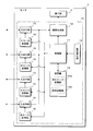
- FIG. 2 is a block diagram showing the configuration of the monitor 1.
- the monitor 1 according to the present embodiment includes a display unit 2 and a display control unit 10 that performs control to display an image on the display unit 2.
- the display unit 2 is configured using, for example, a liquid crystal panel, and displays an image based on an image signal given from the display control unit 10.
- the display control unit 10 includes a control unit 11, an image generation unit 12, a setting reception unit 13, a storage unit 14, four input / output units 15, and four EDID (Extended Display Identification Data) storage units 16.
- EDID Extended Display Identification Data
- the control unit 11 is configured by using an arithmetic processing device such as a CPU (Central Processing Unit) or a microcontroller, and performs various control processing and arithmetic processing related to image display.
- the image generation unit 12 generates a display image based on one or a plurality of images given from the input / output unit 15 and outputs the generated display image as an image signal to the display unit 2 to perform image display. .
- the control unit 11 can control the display mode of the image on the display unit 2 by giving a control command to the image generation unit 12.
- the setting accepting unit 13 accepts various settings related to the image display of the monitor 1 by accepting a user operation on one or a plurality of push buttons provided on the housing of the monitor 1, for example.
- the setting reception unit 13 notifies the control unit 11 of the contents of the received operation.
- a setting menu or the like is displayed on the display unit 2 when setting is accepted.
- the control unit 11 stores the received setting in the setting storage unit 14b of the storage unit 14 and gives a control command to control the operation of the image generation unit 12 according to the received setting.
- the storage unit 14 is configured by using a non-volatile memory element that can rewrite data such as an EEPROM (Electrically-Erasable-Programmable-Read-Only Memory) or a flash memory.
- the storage unit 14 stores various data necessary for the control process of the control unit 11.
- the storage unit 14 includes an all EDID storage unit 14a and a setting storage unit 14b.
- the all EDID storage unit 14a stores all EDID patterns used in the present system.
- the setting storage unit 14b stores the setting received by the setting receiving unit 13.
- the EDID includes, for example, information relating to manufacture such as the manufacturer, model name, serial number and date of manufacture of the monitor 1 and information necessary for display such as display resolution, horizontal frequency, vertical frequency and clock frequency of the monitor 1. It is data to include.
- the PC 5 can output an image suitable for display on the monitor 1 by acquiring the EDID from the monitor 1 at the time of startup or when connected to the monitor 1 by a cable, for example.
- the input / output unit 15 has a terminal for connecting a signal transmission cable, and is connected to the PC 5 through the cable.
- the monitor 1 has four input / output units 15 and can connect four PCs 5.
- the input / output unit 15 receives the image signal output from the PC 5 and supplies the image generation unit 12 with an image related to the input image signal.
- the input / output unit 15 can output information to the PC 5 via a connected cable.
- the input / output unit 15 outputs the EDID stored in the EDID storage unit 16 to the PC 5 connected via a cable.
- the EDID storage unit 16 is configured by using a rewritable nonvolatile memory element such as an EEPROM. However, the EDID storage unit 16 may be configured by using a rewritable volatile memory element such as SRAM (Static Random Access Memory) or DRAM (Dynamic Random Access Memory).
- the monitor 1 has four EDID storage units 16 and is provided in the input / output unit 15 in a one-to-one correspondence.
- the EDID storage unit 16 stores the EDID given from the control unit 11.
- the control unit 11 can store different EDIDs in each of the four EDID storage units 16.
- the EDID stored in the EDID storage unit 16 is output from the corresponding input / output unit 15 to the PC 5.
- FIG. 3 is a block diagram showing the configuration of the PC 5.
- the PC 5 includes a processing unit 51, an operation unit 52, an image generation unit 53, an input / output unit 54, an EDID storage unit 55, and the like.
- the processing unit 51 is configured using an arithmetic processing device such as a CPU or MPU (Micro-Processing Unit).
- the processing unit 51 performs various processes by reading and executing a program stored in a hard disk (not shown).
- the operation unit 52 receives a user operation using an input device such as a mouse or a keyboard, for example, and notifies the processing unit 51 of the received operation content.
- the image generation unit 53 generates an image to be displayed on the monitor 1 in accordance with the processing of the processing unit 51.
- the input / output unit 54 has a terminal for connecting a signal transmission cable, and is connected to the monitor 1 via the cable.
- the input / output unit 54 outputs an image to the monitor 1 by outputting an image signal related to the image generated by the image generation unit 53 to the cable.
- the input / output unit 54 receives information from the monitor 1 via a connected cable.
- EDID is input from the monitor 1 to the input / output unit 54.
- the input / output unit 54 stores the input EDID in the EDID storage unit 55.
- the EDID storage unit 55 is configured using a memory element such as EEPROM, SRAM, or DRAM, or is provided using a part of a storage area such as a cache memory, main memory, or hard disk of the PC 5.
- the EDID storage unit 55 stores the EDID input from the monitor 1 in the input / output unit 54.
- the EDID stored in the EDID storage unit 55 is given to the image generation unit 53.
- the image generation unit 53 determines the specifications of the image to be generated, such as the resolution of the image, according to the given EDID.
- the display system according to the present embodiment can simultaneously display one or a plurality of images on one monitor 1 among the four images output by the four PCs 5.
- the display method can be selected from two types, PbyP that divides the display screen of the monitor 1 into a plurality and PinP that displays another image superimposed on one image.
- PbyP that divides the display screen of the monitor 1 into a plurality
- PinP that displays another image superimposed on one image.
- FIG. 4 is a schematic diagram for explaining the PbyP function.
- the display screen of the monitor 1 can be divided into two, three, or four to display a plurality of images.
- 4A is a layout in which the display screen is divided into two vertically and the output images of the two PCs 5 are appropriately assigned to the respective divided areas for display. The user can set which two output images of the four PCs 5 are to be displayed and which output image of the PC 5 is assigned to each divided area according to his / her preference.
- 4B is a layout in which the display screen is divided into left and right parts, and the output images of the two PCs 5 are appropriately assigned to the respective divided areas for display.
- 4C is a layout in which the right area of the two-division layout 2 in FIG. 4B is further divided into upper and lower parts, and the output images of the three PCs 5 are appropriately assigned to the respective divided areas for display.
- 4D is a layout in which the left area of the two-division layout 2 in FIG. 4B is further divided into upper and lower parts, and the output images of the three PCs 5 are appropriately assigned to the respective divided areas and displayed.
- 4E is a layout in which the display screen is divided into four parts vertically and horizontally, and the output images of the four PCs 5 are appropriately assigned to the respective divided areas for display.
- the resolution of the display screen is represented by the number of horizontal pixels ⁇ the number of vertical pixels, and the resolution of the display screen of the monitor 1 according to this embodiment is 3840 ⁇ 2160.
- Each PC 5 can generate and output an image having at least a resolution of 3840 ⁇ 2160.
- the PC 5 When displaying the output image of one PC 5 using the entire display screen of the monitor 1 (so-called single display), the PC 5 outputs an image having a resolution of 3840 ⁇ 2160, and the monitor 1 converts the input image to the resolution. Can be displayed on the display unit 2 without any change.
- the monitor 1 controls the operation of each PC 5 so that each PC 5 outputs an image having a resolution suitable for each divided region.
- the monitor 1 stores a plurality of EDIDs having different resolutions in all the EDID storage units 14 a of the storage unit 14.
- the control unit 11 of the monitor 1 reads out the EDID having a resolution suitable for each divided region from the entire EDID storage unit 14a based on the correspondence between the divided region and the PC 5 that displays an image in the divided region.
- the control unit 11 stores the EDID read for each divided region in the EDID storage unit 16 corresponding to the input / output unit 15 to which the PC 5 associated with each divided region is connected.
- the control unit 11 electrically disconnects the connection with the PC 5 at the input / output unit 15 and then restores the connection.
- the PC 5 is disconnected from the monitor 1, and therefore acquires the EDID when reconnected to the monitor 1.
- the PC 5 gives an EDID acquisition request to the monitor 1, and in response, the EDID stored in the EDID storage unit 16 is output from the input / output unit 15 of the monitor 1 to the PC 5.
- the PC 5 stores the EDID acquired from the monitor 1 in the EDID storage unit 55, and the image generation unit 53 generates an image having a resolution corresponding to the EDID and outputs the image from the input / output unit 54 to the monitor 1.
- the control unit 11 of the monitor 1 stores the EDID in the EDID storage unit 16 and then interrupts and restores the connection with the PC 5 at the input / output unit 15, thereby giving the EDID having a desired resolution to the PC 5.
- the control unit 11 can store EDIDs having different resolutions in the four EDID storage units 16, and can output images having different resolutions to the four PCs 5, respectively.
- the image generation unit 12 of the monitor 1 can acquire an image with a resolution suitable for each divided area from the PC 5, and can display the PbyP image shown in FIG. 4 without performing image reduction processing.
- the control unit 11 performs processing for giving the EDID to the PC 5 when the monitor 1 is activated and when the setting accepting unit 13 changes a setting related to PbyP.
- an HDMI cable includes an HPD (Hot Plug Detect) line for detecting whether or not a device is connected and a DDC (Display Data Channel) line for transmitting and receiving data.
- HPD Hot Plug Detect
- DDC Display Data Channel
- the monitor 1 changes the hot plug detection signal from a low level to a high level by a startup process such as power-on.
- the PC 5 monitors the hot plug detection signal of the HPD line, and determines that the monitor 1 is connected when the hot plug detection signal changes to a high level. Thereafter, the PC 5 acquires the EDID stored in the EDID storage unit 16 of the monitor 1 via the DDC line, and generates and outputs an image at the resolution of the acquired EDID.
- the monitor 1 changes the hot plug detection signal to the low level and stores the new EDID in the EDID storage unit 16. Thereafter, the hot plug detection signal is changed to a high level.
- the PC 5 determines that the connection with the monitor 1 is cut off and then reconnected.
- the PC 5 acquires a new EDID from the monitor 1 via the DDC line, and changes the resolution of the image to be output.
- the monitor 1 can cause the PC 5 to acquire the EDID and change the resolution of the output image by controlling the hot plug detection signal.
- FIG. 5 is a schematic diagram showing an example of EDID.
- type 1 EDID has a resolution of 3840 ⁇ 2160 and corresponds to the entire display unit 2 of the monitor 1.
- Type 2 EDID has a resolution of 1920 ⁇ 1080 and is 1 ⁇ 4 the size of the display area of the display unit 2.
- Type 3 EDID has a resolution of 1920 ⁇ 2160, and corresponds to a vertically long area when the display area of the display unit 2 is divided into left and right parts.
- Type 4 EDID has a resolution of 3840 ⁇ 1080 and corresponds to a horizontally long area when the display area of the display unit 2 is divided into two vertically.
- Type 5 EDID has a resolution of 1280 ⁇ 720, which is smaller than Type 2.
- type 1 EDID When displaying the output image of one PC 5 using the entire display area of the monitor 1, type 1 EDID is used. When performing split display using the PbyP function, type 2, 3 and 4 EDID are used. When performing display using the PinP function described later, type 1, 2, and 5 EDID are used.
- FIGS. 6 and 7 are schematic diagrams for explaining an example of a change in EDID in the PbyP function.
- the names of the ports 1 to 4 are assigned to the four input / output units 15 of the monitor 1 to distinguish them.
- a table in which the port number of the input / output unit 15, the type of EDID given to each port, and whether or not to display an input image to this port is described. is there.
- the layout of the display screen by the PbyP function is illustrated, and the port displayed in each divided area is indicated by which port the image displayed in each divided area is. is there.
- the three-division layout 2 shown in FIG. 4D is first selected.
- the image of port 1 is displayed in the upper left area
- the image of port 2 is displayed in the lower left area
- port 3 is displayed in the right area.
- type 2 EDID is given to the PC 5 connected to the input / output unit 15 of the port 1 and port 2.
- the PC 5 connected to the port 3 is given a type 3 EDID.
- the PC 5 connected to the non-display port 4 may be given any EDID, but in this example, it is assumed that a type 1 EDID is given.
- the layout is changed to the two-split layout 1 shown in FIG. 4A.
- port 2 is assigned to the upper area
- port 3 is assigned to the lower area (see the lower part of FIG. 6). Since the control unit 11 of the monitor 1 needs to change the resolution of the output image of the PC 5 connected to the port 2 and the port 3, the type 4 EDID is read from the entire EDID storage unit 14a, and the port 2 and the port 3 are read. The type 4 EDID is stored in the corresponding EDID storage unit 16 and the PC 5 connected to the port 2 and the port 3 acquires the EDID. For the PC 5 connected to the non-display ports 1 and 4, it is not necessary to change the resolution, and therefore the EDID is not changed by the control unit 11.
- the control unit 11 does not change the EDID for the non-display ports 1 and 3. Further, since it is not necessary to change the resolution of the port 2 assigned to the lower area, the control unit 11 does not change the EDID. On the other hand, the port 4 assigned to the upper area needs to change the EDID from type 1 to type 4. Therefore, the control unit 11 stores the type 4 EDID in the EDID storage unit 16 corresponding to the port 4 and causes the PC 5 connected to the port 4 to acquire the EDID.
- the control unit 11 needs to give a type 2 EDID to all ports. However, since the port 1 has already been given a type 2 EDID, the control unit 11 does not change the EDID for the port 1 or the like.
- the control unit 11 stores the EDID of type 2 in the EDID storage unit 16 corresponding to the ports 2 to 4, and causes the PC 5 connected to the ports 2 to 4 to acquire the EDID.
- the monitor 1 can give EDIDs having different resolutions to the four PCs 5 connected to the four input / output units 15.
- the control unit 11 of the monitor 1 gives each PC 5 an EDID corresponding to the changed setting. Controls the resolution of the output image.
- the control unit 11 gives a new EDID to the PC 5 that needs to change the resolution by changing the setting, but does not give the EDID to the PC 5 that does not need to change the resolution.
- FIG. 8 is a schematic diagram for explaining the PinP function.
- an output image of one PC 5 is displayed on the entire display screen of the monitor 1, and a window is provided on a predetermined area of this image, and an output image of another PC 5 is provided in this window.
- the user can select either a large window (see FIG. 8A) or a small window (see FIG. 8B) for the window to be displayed.
- the display position of the window can be selected from four places: upper right, lower right, upper left, or lower left.
- the user can set the correspondence between the main image displayed on the entire display screen, the sub image displayed on the window, and the ports 1 to 4 as desired.
- the control unit 11 of the monitor 1 gives the type 1 EDID shown in FIG. 5 to the PC 5 connected to the port set in the main image displayed on the entire display unit 2. Further, the control unit 11 gives a type 2 or type 5 EDID to the PC 5 connected to the port set in the sub-image displayed in the window. That is, the control unit 11 gives a type 2 EDID to the PC 5 when performing display by a large window, and gives a type 5 EDID when performing display by a small window.
- the control unit 11 of the monitor 1 changes the EDID according to the changed setting when the setting change such as the window size change of the PinP function or the assignment change of the main image and the sub image is performed. Is given to each PC 5. That is, the control unit 11 stores a new EDID in the EDID storage unit 16 corresponding to the input / output unit 15 to which the PC 5 to be changed is connected, and disconnects the connection with the PC 5 at the input / output unit 15. By restoring the connection, the PC 5 is made to acquire a new EDID. Thereby, the control unit 11 controls the resolution of the image output from each PC 5.
- the control unit 11 gives a new EDID to the PC 5 that needs to change the resolution of the output image when the setting related to the PinP function is changed, but does not need to change the resolution. Does not give an EDID. For example, when the window size is changed, the control unit 11 gives a new EDID to the PC 5 that outputs the sub-image in the window, but does not need to give the EDID to the PC 5 that outputs the main image. When the display position of the window is changed, the control unit 11 does not need to change the resolution, and therefore does not need to give EDID to the PC 5.
- FIG. 9 is a flowchart showing the procedure of the display control process accompanying the setting change by the monitor 1. Note that the process shown in this flowchart is a common process in both cases of the PbyP function and the PinP function.
- the control unit 11 of the monitor 1 determines whether or not the setting reception unit 13 has received a setting change regarding the PbyP function or the PinP function (step S1). When the setting change is not received (S1: NO), the control unit 11 stands by until the setting change is received. When the setting change is accepted (S1: YES), the control unit 11 initializes the value of the variable i to 1 (step S2).
- the variable i is a variable indicating the number of the port to be processed, and is realized by using a storage area such as a register or a memory of the control unit 11, for example.
- Control unit 11 selects port i as a processing target (step S3).
- the control unit 11 determines whether or not to display the image input to the port i based on the layout setting or the port assignment setting for the area (step S4).
- the control unit 11 advances the process to step S9.
- the control unit 11 further determines whether or not the resolution of the port i needs to be changed (step S5).
- the control unit 11 advances the process to step S9.
- the control unit 11 When it is determined that the resolution of the port i needs to be changed (S5: YES), the control unit 11 reads out the EDID suitable for the resolution of the port i after the setting change from all the EDID storage units 14a of the storage unit 14. (Step S6). The control unit 11 stores the read EDID in the EDID storage unit 16 corresponding to the port i (step S7). The control unit 11 causes the PC 5 to acquire a new EDID by causing the input / output unit 15 of the port i to be disconnected and returned to the PC 5 (step S8).
- control unit 11 determines whether or not processing has been completed for all ports (step S9).
- the control unit 11 adds 1 to the value of the variable i (step S10), returns the process to step S3, and performs the above-described process for all ports. .
- the control unit 11 finishes the display control process.
- the monitor 1 displays a setting change screen on the display unit 2 in order to accept settings relating to the PbyP function and the PinP function. For example, when the output image from the PC 5 is displayed on the display unit 2 at the approximate center of the display area of the display unit 2, the setting change screen is displayed over the image. That is, the setting change screen is displayed as a so-called OSD (On-Screen Display).
- OSD On-Screen Display
- the setting change screen displayed by the monitor 1 according to the present embodiment has a hierarchical structure, and a plurality of screens are switched and displayed in accordance with a user operation.
- 10 to 12 are display examples of the setting change screen.
- the control unit 11 of the monitor 1 displays a menu top screen (not shown) on which a list of items related to setting changes is displayed.
- the control unit 11 displays a screen for accepting selection of the display mode as shown in the upper part of FIG.
- “PbyP”, “PinP”, or “Single” can be selected.
- “Single” is a display mode in which the output image of one PC 5 is displayed in the entire display area of the display unit 2 and the output images of other PCs 5 are not displayed.
- the control unit 11 displays a PbyP setting screen for performing various settings regarding the PbyP function on the display unit 12. (See the lower part of FIG. 10).
- settings such as “Color Mode”, “Sound Source”, “Layout”, and port allocation for divided areas can be performed. Note that description of the “Color Mode” and “Sound Source” settings is omitted.
- the “Layout” setting one of the display screen division modes shown in FIGS. 4A to 4E can be selected. Based on the layout selected in the “Layout” setting, a schematic diagram showing a display mode is displayed on the PbyP setting screen.
- a display mode in which the display area is divided into left and right parts is shown as a schematic diagram.
- a number is assigned to each divided region, and on the PbyP setting screen, the correspondence between the divided region and the port based on this number is displayed on the left side of the schematic diagram.
- port 1 is associated with the left region divided into two
- port 2 is associated with the right region.
- the control unit 11 displays a layout selection screen for selecting the layout of PbyP on the display unit 12. (Refer to the upper part of FIG. 11).
- the layout selection screen the five layouts shown in FIG. 4 are displayed as Layouts 1 to 5, and any one of the layouts can be selected.
- the control unit 11 when the setting accepting unit 13 accepts the selection of Layout 5 on the layout selection screen in the upper part of FIG. 11, the control unit 11 returns the setting change screen to the PbyP setting screen (see the lower part of FIG. 11).
- the PbyP setting screen displayed at this time reflects the selection content on the layout selection screen.
- Layout 5 is selected as the “Layout” setting, and a display mode in which the display area is divided into four parts is shown as a schematic diagram.
- the control unit 11 selects a port for selecting a port to be assigned to the divided region 1.
- the screen is displayed on the display unit 12 (see the upper part of FIG. 12).
- a list of names for identifying the four ports (that is, the input / output unit 15) of the monitor 1 is displayed, and the user can select one from these.
- four names “DisplayPort1,” “DisplayPort2,” “HDMI,” and “DVI” are displayed as options on the port selection screen.
- the control unit 11 returns the display of the setting change screen to the PbyP setting screen (see the lower part of FIG. 12).
- the PbyP setting screen displayed at this time reflects the selection content on the port selection screen.
- “DisplayPort2” is assigned to the divided area 1
- “DisplayPort1” is assigned to the divided area 2.
- the monitor 1 displays the setting change screen on the display unit 2 because the setting receiving unit 13 receives various setting change operations.
- the setting change screen according to the present embodiment has the following hierarchical structure.
- First layer Top screen (not shown)
- Second layer display mode selection screen (upper part of FIG. 10), other (not shown)
- 3rd layer PbyP setting screen (lower part of FIG. 10, etc.), PinP setting screen (not shown), single setting screen (not shown)
- Fourth layer layout selection screen (upper part of FIG. 11), port selection screen (upper part of FIG. 12), others (not shown)
- the control unit 11 of the monitor 1 first displays the top screen of the first layer, and displays the display mode selection screen of the second layer or other screen according to the operation on the top screen.
- the control unit 11 displays a PbyP setting screen, a PinP setting screen, or a single setting screen of the third layer in accordance with an operation on the display mode selection screen of the second layer.
- the control unit 11 displays a layout selection screen, a port selection screen, or other screens in the fourth layer in response to an operation on the PbyP setting screen in the third layer.
- the control unit 11 displays the screen of the next higher layer.
- ⁇ Summary> output images from a plurality of PCs 5 are input to the monitor 1, and the image generation unit 12 of the monitor 1 generates a display image in which the plurality of input images are appropriately arranged to display the display unit. 2 is displayed.
- the control unit 11 of the monitor 1 controls the resolution of an image output by the PC 5 by giving each PC 5 EDID (display specification information) including information related to the resolution of image display. At this time, the monitor 1 can give EDIDs having different resolutions to the plurality of PCs 5.
- the monitor 1 can give each PC 5 an EDID suitable for the resolution of each input image in the display image, and cause each PC 5 to output an image with a desired resolution. Even if the resolution of each input image in the display image is different, the monitor 1 can give each PC 5 EDID having a different resolution.
- the monitor 1 can acquire an input image having a desired resolution, and can generate a display image and display it on the display unit 2 without performing image reduction processing or the like.
- the setting receiving unit 13 of the monitor 1 receives a setting related to the generation condition of the display image, and the image generating unit 12 generates a display image corresponding to the received setting and displays the display unit 2.
- the image generating unit 12 generates a display image corresponding to the received setting and displays the display unit 2.
- To display for example, in the case of the PbyP function that divides the display area of the display unit 2 into a plurality of parts and displays an image from the PC 5 in each divided area, settings relating to the division mode of the display area (selection of layout) or display with each divided area
- the setting receiving unit 13 can receive settings (port selection) and the like related to the association with the input image to be performed.
- the setting accepting unit 13 can accept the settings related to the above. These settings are settings that may change the resolution of each image to be displayed.
- the control unit 11 of the monitor 1 gives each PC 5 an EDID corresponding to the new setting, and displays an image with a resolution corresponding to the changed setting. Output to PC5.
- the control unit 11 does not give EDID to the PC 5 that does not require the resolution change before and after the setting change. Thereby, increase of the processing load of PC5 can be suppressed.
- the monitor 1 does not give EDID to the PC 5 satisfying a specific condition, for example, when the resolution is not changed even if the setting is changed as described above, and gives EDID to other image output apparatuses.
- the specific condition is not limited to this, and may be, for example, a condition such as a PC 5 that the user has set not to give EDID, or a PC 5 that does not have a function such as acquisition of EDID. Condition may be sufficient.
- the apparatus that generates and outputs an image to be displayed on the monitor 1 is the PC 5.
- the image output apparatus may be a digital camera, video camera, hard disk recorder, DVD ( Digital Versatile Disc) may be a player or a game machine.
- the monitor 1 is configured to be able to connect four PCs 5.
- the present invention is not limited to this, and the monitor 1 may be configured to be capable of connecting three or less or five or more PCs 5.
- the monitor 1 has a PbyP function that divides the display area of the display unit 2 and displays a plurality of images, and a PinP function that arranges and displays other images within a predetermined area of one image.
- the present invention is not limited to this, and may be configured to have either a PbyP function or a PinP function.
- the display method of a several image is not restricted to PbyP or PinP, A various other method can be employ
- each PC 5 outputs one image, but the present invention is not limited to this.
- One PC 5 may be configured to output a plurality of images.
- the monitor 1 uses two divided regions to display two images from one PC 5 when displaying PbyP. can do.
- the monitor 1 is connected to the two input / output units 15 to one PC 5 via two cables.
- the monitor 1 does not need to determine whether the PC 5 connected to the two input / output units 15 is one PC 5 or two PCs 5.
- the PC 5 connected to the monitor 1 via two cables acquires the EDID from the monitor 1 via each cable, and generates and outputs an image with a resolution corresponding to the acquired EDID.
- FIG. 13 is a schematic diagram illustrating a configuration of a display system according to the first modification.
- the display system according to the modified example 1 is configured such that the display control device 210 is interposed between the monitor 201 and the plurality of PCs 5.
- the configuration of the display control device 210 is substantially the same as that of the display control unit 10 of the monitor 1 shown in FIG. That is, the display control device 210 can connect four PCs 5 to the four input / output units 15, and the image generation unit 12 generates display images in which input images from the four PCs 5 are appropriately arranged. Output to the monitor 201.
- the monitor 201 may display the display image given from the display control device 210.
- the configuration of the display control device 210 according to the first modification is substantially the same as the configuration of the display control unit 10 of the monitor 1 shown in FIG.
- the image generation unit 12 generates a display image such as PbyP or PinP based on the images input to the four input / output units 15, and outputs the image generated by the image generation unit 12.
- the display control device 210 and the monitor 201 are connected via an image signal transmission cable or the like, and an image output from the display control device 210 is input to the monitor 201 via this cable.
- the monitor 201 can display an image such as PbyP or PinP only by displaying the input image.
- the monitor 1 does not store all the EDIDs corresponding to a plurality of resolutions, but stores each EDID.
- each PC 5 stores five EDIDs (EDID0 to EDID4) having different resolutions.
- the monitor 1 gives a change command specifying the EDID number (0 to 4) to the PC 5 to be changed.
- the PC 5 given a change command from the monitor 1 reads the EDID of the designated number, generates an image with a resolution corresponding to the read EDID, and outputs it to the monitor 1.
- the monitor 1 stores a plurality of EDIDs in the entire EDID storage unit 14a of the storage unit 14, and the control unit 11 assigns appropriate EDIDs to all EDIDs in response to setting changes such as PbyP or PinP.
- the configuration is such that the data is read from the storage unit 14a and given to each EDID storage unit 16, the present invention is not limited thereto.
- each EDID storage unit 16 stores all EDIDs.
- the control unit 11 gives an instruction as to which EDID to use to each EDID storage unit 16 according to the received setting.
- Each EDID storage unit 16 determines which EDID to use from all the stored EDIDs in accordance with a command given from the control unit 11.
- the EDID storage unit 16 gives the EDID corresponding to the command from the control unit 11 to the PC 5.
- the monitor 1 does not give EDID to the PC 5 whose resolution is not changed even when the setting change is accepted.
Landscapes
- Engineering & Computer Science (AREA)
- Physics & Mathematics (AREA)
- Computer Hardware Design (AREA)
- General Physics & Mathematics (AREA)
- Theoretical Computer Science (AREA)
- Controls And Circuits For Display Device (AREA)
- User Interface Of Digital Computer (AREA)
- Digital Computer Display Output (AREA)
- Two-Way Televisions, Distribution Of Moving Picture Or The Like (AREA)
Abstract
L'invention concerne un dispositif de commande d'affichage dans lequel l'unité de génération d'image (12) d'un moniteur (1) génère et affiche une image d'affichage dans laquelle les images d'entrée d'une pluralité de PC sont agencées de façon appropriée. Une unité de commande (11) commande la résolution des images qui sont générées par les PC en fournissant des données d'identification d'affichage étendues (EDID), comprenant des informations relatives à la résolution d'affichage d'image, à chacun des PC. Le moniteur (1) est capable de fournir des EDID, qui diffèrent par rapport à la résolution, à une pluralité de PC. Lorsqu'une unité de réception de paramètres (13) reçoit un changement de paramètre, l'unité de commande (11) fournit les EDID, qui correspondent au nouveau réglage, à chacun des PC et amènent chacun des PC à générer une image ayant une résolution qui correspond aux paramètres modifiés. Toutefois, l'unité de commande (11) ne fournit pas d'EDID à un PC qui ne requiert pas de changement de résolution avant ou après une modification de paramètres.
Applications Claiming Priority (2)
| Application Number | Priority Date | Filing Date | Title |
|---|---|---|---|
| JP2014154014A JP2016031468A (ja) | 2014-07-29 | 2014-07-29 | 表示制御装置、表示装置及び表示システム |
| JP2014-154014 | 2014-07-29 |
Publications (1)
| Publication Number | Publication Date |
|---|---|
| WO2016017635A1 true WO2016017635A1 (fr) | 2016-02-04 |
Family
ID=55217535
Family Applications (1)
| Application Number | Title | Priority Date | Filing Date |
|---|---|---|---|
| PCT/JP2015/071367 Ceased WO2016017635A1 (fr) | 2014-07-29 | 2015-07-28 | Dispositif de commande d'affichage, dispositif d'affichage et système d'affichage |
Country Status (2)
| Country | Link |
|---|---|
| JP (1) | JP2016031468A (fr) |
| WO (1) | WO2016017635A1 (fr) |
Families Citing this family (7)
| Publication number | Priority date | Publication date | Assignee | Title |
|---|---|---|---|---|
| JP2017044968A (ja) * | 2015-08-28 | 2017-03-02 | キヤノン株式会社 | 表示装置、制御方法及びプログラム |
| JP2019207349A (ja) * | 2018-05-30 | 2019-12-05 | シャープ株式会社 | 表示装置及び表示方法 |
| KR102617847B1 (ko) * | 2019-03-19 | 2023-12-22 | 엘에스일렉트릭(주) | 모니터링 화면 변경에 따른 오브젝트 변환장치 |
| JP7517013B2 (ja) * | 2020-09-17 | 2024-07-17 | 住友電気工業株式会社 | コンテンツ視聴装置、ログ収集システムおよびログ収集方法 |
| CN114205660A (zh) * | 2020-09-18 | 2022-03-18 | 明基智能科技(上海)有限公司 | 荧幕解析度调整方法及其显示装置 |
| KR20220096699A (ko) * | 2020-12-31 | 2022-07-07 | 삼성전자주식회사 | 전자 장치 및 그 동작 방법 |
| JP2022178820A (ja) * | 2021-05-21 | 2022-12-02 | シャープ株式会社 | 映像表示装置及び映像表示方法 |
Citations (4)
| Publication number | Priority date | Publication date | Assignee | Title |
|---|---|---|---|---|
| JP2004170822A (ja) * | 2002-11-21 | 2004-06-17 | Nanao Corp | 解像度設定方法及びインタフェース装置 |
| JP2007158903A (ja) * | 2005-12-07 | 2007-06-21 | Sharp Corp | Hdmi出力時の解像度切換え手段 |
| JP2011081188A (ja) * | 2009-10-07 | 2011-04-21 | Sanyo Electric Co Ltd | 投写型映像表示装置 |
| JP2014048921A (ja) * | 2012-08-31 | 2014-03-17 | Canon Inc | 表示装置、映像出力装置、その制御方法 |
-
2014
- 2014-07-29 JP JP2014154014A patent/JP2016031468A/ja active Pending
-
2015
- 2015-07-28 WO PCT/JP2015/071367 patent/WO2016017635A1/fr not_active Ceased
Patent Citations (4)
| Publication number | Priority date | Publication date | Assignee | Title |
|---|---|---|---|---|
| JP2004170822A (ja) * | 2002-11-21 | 2004-06-17 | Nanao Corp | 解像度設定方法及びインタフェース装置 |
| JP2007158903A (ja) * | 2005-12-07 | 2007-06-21 | Sharp Corp | Hdmi出力時の解像度切換え手段 |
| JP2011081188A (ja) * | 2009-10-07 | 2011-04-21 | Sanyo Electric Co Ltd | 投写型映像表示装置 |
| JP2014048921A (ja) * | 2012-08-31 | 2014-03-17 | Canon Inc | 表示装置、映像出力装置、その制御方法 |
Non-Patent Citations (1)
| Title |
|---|
| "Press Release | NEC Display Solutions 24-gata 4K Wide Ekisho Display o Hatsubai -Koseisai Hyoji ni yori Gazo no Rinjokan, Okuyukikan o Hyogen", 7 February 2014 (2014-02-07), Retrieved from the Internet <URL:http://www.nec-display.com/jp/press/2014/0207.html> [retrieved on 20151016] * |
Also Published As
| Publication number | Publication date |
|---|---|
| JP2016031468A (ja) | 2016-03-07 |
Similar Documents
| Publication | Publication Date | Title |
|---|---|---|
| WO2016017635A1 (fr) | Dispositif de commande d'affichage, dispositif d'affichage et système d'affichage | |
| KR102545078B1 (ko) | 디스플레이장치, 그 제어방법 및 시스템 | |
| US20120050314A1 (en) | Automatic split-screen controller | |
| CN105957496A (zh) | 显示设备的控制方法、控制装置以及显示设备 | |
| US9787937B1 (en) | Display apparatus for video wall and operation method thereof | |
| US20160299683A1 (en) | Display apparatus and control method thereof | |
| US8839105B2 (en) | Multi-display system and method supporting differing accesibility feature selection | |
| TWI518673B (zh) | 影像切換器及其切換方法 | |
| JP2013153410A (ja) | Av機器 | |
| KR102061869B1 (ko) | 전자 장치 및 영상 표시 방법 | |
| KR20170046989A (ko) | 다중 디스플레이 시스템을 구성하는 디스플레이 장치 및 그 제어 방법 | |
| EP3923128B1 (fr) | Appareil électronique et son procédé de commande | |
| US20120001913A1 (en) | Computer system and control method thereof | |
| US12204699B2 (en) | Routing input to on-screen display | |
| US10430143B2 (en) | Image output apparatus, image display apparatus, control method of image output apparatus, and control method of image display apparatus | |
| JP2015165617A (ja) | 映像表示装置 | |
| KR102743249B1 (ko) | 전자 장치 및 그 제어 방법 | |
| KR20090047689A (ko) | 멀티 스크린 시스템 및 그 구현 방법 | |
| CN113126945A (zh) | 电子装置及显示装置的防烙印方法 | |
| TWI627582B (zh) | 顯示裝置及其延伸顯示能力辨識資訊置換方法 | |
| WO2018087881A1 (fr) | Dispositif d'affichage et procédé d'affichage d'image du dispositif d'affichage | |
| CN106415473B (zh) | 显示器装置及其控制方法 | |
| CN109214977B (zh) | 图像处理装置及其控制方法 | |
| US11202028B2 (en) | Display device configuring multi display system and control method thereof | |
| TWI475886B (zh) | 顯示控制裝置 |
Legal Events
| Date | Code | Title | Description |
|---|---|---|---|
| 121 | Ep: the epo has been informed by wipo that ep was designated in this application |
Ref document number: 15827711 Country of ref document: EP Kind code of ref document: A1 |
|
| NENP | Non-entry into the national phase |
Ref country code: DE |
|
| 122 | Ep: pct application non-entry in european phase |
Ref document number: 15827711 Country of ref document: EP Kind code of ref document: A1 |