WO2016017639A1 - 圧縮空気貯蔵発電装置及び圧縮空気貯蔵発電方法 - Google Patents
圧縮空気貯蔵発電装置及び圧縮空気貯蔵発電方法 Download PDFInfo
- Publication number
- WO2016017639A1 WO2016017639A1 PCT/JP2015/071374 JP2015071374W WO2016017639A1 WO 2016017639 A1 WO2016017639 A1 WO 2016017639A1 JP 2015071374 W JP2015071374 W JP 2015071374W WO 2016017639 A1 WO2016017639 A1 WO 2016017639A1
- Authority
- WO
- WIPO (PCT)
- Prior art keywords
- tank
- power
- compressed air
- capacity
- air storage
- Prior art date
- Legal status (The legal status is an assumption and is not a legal conclusion. Google has not performed a legal analysis and makes no representation as to the accuracy of the status listed.)
- Ceased
Links
Images








Classifications
-
- F—MECHANICAL ENGINEERING; LIGHTING; HEATING; WEAPONS; BLASTING
- F04—POSITIVE - DISPLACEMENT MACHINES FOR LIQUIDS; PUMPS FOR LIQUIDS OR ELASTIC FLUIDS
- F04B—POSITIVE-DISPLACEMENT MACHINES FOR LIQUIDS; PUMPS
- F04B23/00—Pumping installations or systems
- F04B23/02—Pumping installations or systems having reservoirs
-
- F—MECHANICAL ENGINEERING; LIGHTING; HEATING; WEAPONS; BLASTING
- F03—MACHINES OR ENGINES FOR LIQUIDS; WIND, SPRING, OR WEIGHT MOTORS; PRODUCING MECHANICAL POWER OR A REACTIVE PROPULSIVE THRUST, NOT OTHERWISE PROVIDED FOR
- F03D—WIND MOTORS
- F03D9/00—Adaptations of wind motors for special use; Combinations of wind motors with apparatus driven thereby; Wind motors specially adapted for installation in particular locations
- F03D9/007—Adaptations of wind motors for special use; Combinations of wind motors with apparatus driven thereby; Wind motors specially adapted for installation in particular locations the wind motor being combined with means for converting solar radiation into useful energy
-
- G—PHYSICS
- G16—INFORMATION AND COMMUNICATION TECHNOLOGY [ICT] SPECIALLY ADAPTED FOR SPECIFIC APPLICATION FIELDS
- G16Z—INFORMATION AND COMMUNICATION TECHNOLOGY [ICT] SPECIALLY ADAPTED FOR SPECIFIC APPLICATION FIELDS, NOT OTHERWISE PROVIDED FOR
- G16Z99/00—Subject matter not provided for in other main groups of this subclass
-
- H—ELECTRICITY
- H02—GENERATION; CONVERSION OR DISTRIBUTION OF ELECTRIC POWER
- H02J—ELECTRIC POWER NETWORKS; CIRCUIT ARRANGEMENTS OR SYSTEMS FOR SUPPLYING OR DISTRIBUTING ELECTRIC POWER; SYSTEMS FOR STORING ELECTRIC ENERGY
- H02J15/00—Systems for storing electric energy specially adapted for power networks
- H02J15/20—Systems for storing electric energy specially adapted for power networks using storage of pneumatic energy, e.g. compressed air energy storage [CAES]
-
- H—ELECTRICITY
- H02—GENERATION; CONVERSION OR DISTRIBUTION OF ELECTRIC POWER
- H02K—DYNAMO-ELECTRIC MACHINES
- H02K7/00—Arrangements for handling mechanical energy structurally associated with dynamo-electric machines, e.g. structural association with mechanical driving motors or auxiliary dynamo-electric machines
- H02K7/18—Structural association of electric generators with mechanical driving motors, e.g. with turbines
- H02K7/1807—Rotary generators
- H02K7/1823—Rotary generators structurally associated with turbines or similar engines
-
- F—MECHANICAL ENGINEERING; LIGHTING; HEATING; WEAPONS; BLASTING
- F03—MACHINES OR ENGINES FOR LIQUIDS; WIND, SPRING, OR WEIGHT MOTORS; PRODUCING MECHANICAL POWER OR A REACTIVE PROPULSIVE THRUST, NOT OTHERWISE PROVIDED FOR
- F03D—WIND MOTORS
- F03D9/00—Adaptations of wind motors for special use; Combinations of wind motors with apparatus driven thereby; Wind motors specially adapted for installation in particular locations
- F03D9/10—Combinations of wind motors with apparatus storing energy
- F03D9/17—Combinations of wind motors with apparatus storing energy storing energy in pressurised fluids
-
- Y—GENERAL TAGGING OF NEW TECHNOLOGICAL DEVELOPMENTS; GENERAL TAGGING OF CROSS-SECTIONAL TECHNOLOGIES SPANNING OVER SEVERAL SECTIONS OF THE IPC; TECHNICAL SUBJECTS COVERED BY FORMER USPC CROSS-REFERENCE ART COLLECTIONS [XRACs] AND DIGESTS
- Y02—TECHNOLOGIES OR APPLICATIONS FOR MITIGATION OR ADAPTATION AGAINST CLIMATE CHANGE
- Y02E—REDUCTION OF GREENHOUSE GAS [GHG] EMISSIONS, RELATED TO ENERGY GENERATION, TRANSMISSION OR DISTRIBUTION
- Y02E10/00—Energy generation through renewable energy sources
- Y02E10/70—Wind energy
- Y02E10/72—Wind turbines with rotation axis in wind direction
-
- Y—GENERAL TAGGING OF NEW TECHNOLOGICAL DEVELOPMENTS; GENERAL TAGGING OF CROSS-SECTIONAL TECHNOLOGIES SPANNING OVER SEVERAL SECTIONS OF THE IPC; TECHNICAL SUBJECTS COVERED BY FORMER USPC CROSS-REFERENCE ART COLLECTIONS [XRACs] AND DIGESTS
- Y02—TECHNOLOGIES OR APPLICATIONS FOR MITIGATION OR ADAPTATION AGAINST CLIMATE CHANGE
- Y02E—REDUCTION OF GREENHOUSE GAS [GHG] EMISSIONS, RELATED TO ENERGY GENERATION, TRANSMISSION OR DISTRIBUTION
- Y02E60/00—Enabling technologies; Technologies with a potential or indirect contribution to GHG emissions mitigation
- Y02E60/16—Mechanical energy storage, e.g. flywheels or pressurised fluids
-
- Y—GENERAL TAGGING OF NEW TECHNOLOGICAL DEVELOPMENTS; GENERAL TAGGING OF CROSS-SECTIONAL TECHNOLOGIES SPANNING OVER SEVERAL SECTIONS OF THE IPC; TECHNICAL SUBJECTS COVERED BY FORMER USPC CROSS-REFERENCE ART COLLECTIONS [XRACs] AND DIGESTS
- Y02—TECHNOLOGIES OR APPLICATIONS FOR MITIGATION OR ADAPTATION AGAINST CLIMATE CHANGE
- Y02E—REDUCTION OF GREENHOUSE GAS [GHG] EMISSIONS, RELATED TO ENERGY GENERATION, TRANSMISSION OR DISTRIBUTION
- Y02E70/00—Other energy conversion or management systems reducing GHG emissions
- Y02E70/30—Systems combining energy storage with energy generation of non-fossil origin
Definitions
- the present invention relates to a compressed air storage power generation apparatus and a compressed air storage power generation method.
- CAES compressed air storage
- Such CAES power generation devices using natural energy are disclosed in, for example, Patent Document 1 and Patent Document 2.
- Patent Document 1 discloses a CAES power generator using wind power.
- Patent Document 2 discloses a CAES power generator using sunlight.
- Power generation using natural energy has long-cycle and short-cycle output fluctuations. Although there is no clear definition that separates long and short periods, long periods vary from several hours to several days. On the other hand, the short period is a fluctuation of about several minutes to less than one hour.
- the long cycle output fluctuation factor is the difference between daytime and nighttime. The short cycle output fluctuation factor is when the sun is temporarily hidden in the clouds.
- long-period output fluctuations are when power generation is stopped due to strong winds or no wind, and short-period output fluctuations are due to wind speed fluctuations.
- CAES power generation devices using natural energy including those disclosed in Patent Document 1 and Patent Document 2 are equipped with a large-capacity compressed air storage tank and store compressed air when the power demand is small. It generates electricity with compressed air stored when it is large.
- a large-capacity tank is not suitable for leveling output fluctuations in a short cycle because it takes a long time to increase the pressure from the start of compression to a pressure suitable for power generation at startup.
- An object of the present invention is to provide a CAES power generator that can cope with both long-cycle and short-cycle fluctuation power.
- a preferred embodiment of the present invention includes a plurality of motors electrically connected in parallel to each other, driven by electric power generated using natural energy, and a plurality of compressions that are mechanically connected to the motors and compress air. And at least two different capacity tanks for storing the air compressed by the compressor, a plurality of expanders driven by compressed air supplied from the tank, and mechanically connected to the expander Among a plurality of generators that are electrically connected in parallel with each other and of the power generated by natural energy, a relatively large-capacity tank is used for long-period fluctuating power, and short-cycle fluctuating power is used. Compression means comprising a control means for performing control for leveling both long-cycle and short-cycle fluctuating power and outputting power corresponding to power demand by using a relatively small capacity tank It is a gas storage power generation system.
- This compressed air storage power generator uses tanks with different capacities for long-cycle and short-cycle fluctuating power. For this reason, both the long-cycle and short-cycle fluctuating power can be leveled, and power corresponding to the power demand can be output. In particular, leveling with good followability can be achieved with respect to short-period fluctuation power. Here, good follow-up indicates that there is little time delay until the target output is reached.
- the relatively small capacity tank preferably has a capacity capable of generating electricity for less than one hour. Further, it is preferable that the relatively large capacity tank has a capacity capable of generating power continuously for one hour or more.
- each tank since it was divided into large capacity and small capacity, each tank has an appropriate capacity for long cycle correspondence and short cycle correspondence, so it does not require a larger tank than necessary, and it is necessary It is possible to prevent the tank from becoming insufficient.
- the small-capacity tank takes a short time to increase the pressure until it reaches a pressure suitable for power generation, and it is easy to always maintain a high pressure. Therefore, the response to short cycle fluctuations is particularly good.
- the control means sets the long-cycle and short-cycle fluctuation powers based on the long-cycle demand curve for long-cycle fluctuation power and the short-cycle reference curve for short-cycle fluctuation power. It is preferable to perform leveling and control according to power demand.
- both the long-cycle and short-cycle fluctuating power are leveled. It is possible to efficiently perform control according to the power demand. This is coupled with the provision of a large-capacity tank for a long cycle and a small-capacity tank for a short cycle, so that more efficient control can be performed.
- the compressor and the generator connected to the relatively small capacity tank are both screw type.
- both the compressor and the expander connected to the relatively large capacity tank are of the screw type.
- the rotational speed control can be performed by adopting a screw type compressor and a generator instead of a turbo type. Further, since the efficiency does not decrease even at a small flow rate (low rotation speed) compared to the turbo type, the control range can be expanded.
- At least one of the compressor and the expander connected to the relatively large capacity tank is a turbo type, and both the compressor and the expander connected to the relatively small capacity tank are a screw type. There may be.
- a small-capacity screw type compressor and expander can be additionally installed in the existing CAES equipment.
- the existing CAES equipment is generally a turbo type, and the existing equipment can be used as it is.
- the compressor and the expander connected to the large-capacity tank are mainly intended to cope with long-period fluctuations, so that the turbo type can also be accommodated.
- At least a small compressor and an expander for short cycle variable power, and at least a large compressor and expander for long cycle variable power.
- the small compressor and the generator are more responsive to the input, so the followability to short cycle fluctuations is improved. Since long-period fluctuations do not require high-accuracy followability compared to short-period fluctuations, large compressors and generators corresponding to the tank capacity can be used. In general, large compressors / generators are more efficient and are suitable for handling long-period fluctuations.
- An inlet-side heat exchanger is provided at the inlet of the tank to exchange heat with air heated by the compressor and heated, and a heat storage unit is provided to store the heat medium exchanged with the inlet-side heat exchanger. It is preferable to provide an outlet side heat exchanger that heats the air discharged from the tank at the outlet by heat exchange with the heat medium discharged from the heat storage unit.
- the heat generated in the compressor is recovered, and the charge / discharge efficiency can be improved by returning it to the air just before the expansion.
- heat generated in the compressor is supplied into the tank together with compressed air. Then, heat is released from the tank to the atmosphere, resulting in energy loss.
- heat is recovered in advance before the compressed air is supplied to the tank, and the temperature of the compressed air in the tank is brought close to the atmospheric temperature. In this way, energy loss due to heat release in the tank can be prevented.
- An external generator different from this generator may be provided at the output part of the generator so that power is generated when the power generated using natural energy is excessively unstable or too small.
- this compressed air storage power generator has a separate power generation system, the output of the power generator using natural energy is reliably maintained even when the output of the power generator using natural energy is unexpectedly unstable, such as failure or long-term shutdown. it can.
- Mine tunnels or underground cavities may be used for relatively large tanks.
- a well-sealed tunnel can be used as a tank, greatly reducing equipment costs.
- the main cost factor is often the manufacture of a large capacity tank. Accordingly, the cost can be greatly reduced by using a well-sealed tunnel or underground cavity as an alternative to a large-capacity tank. This is also effective for cost reduction even when a closed mine shaft or underground cavity is used as a small-capacity tank as well as a large-capacity tank.
- the control means measures the injection side valve for switching to which tank the compressed air is supplied from the compressor, the discharge side valve for switching to which expander the compressed air is supplied from the tank, and the power generation output of natural energy It includes an output sensor, a pressure sensor that measures the pressure in the tank, and a control device, and the control device may open and close the injection side valve and the discharge side valve based on the measurement values of the output sensor and the pressure sensor.
- Another aspect of the present invention includes a plurality of motors electrically connected in parallel to each other, driven by electric power generated using natural energy, and a plurality of motors mechanically connected to the motors and compressing air.
- a compressor at least two different capacity tanks for storing the air compressed by the compressor, a plurality of expanders driven by compressed air supplied from the tank, and the expander mechanically
- a compressed air storage power generation method for a compressed air storage power generation apparatus including a plurality of generators connected and electrically connected in parallel to each other, and among the generated power by natural energy, Use a relatively large capacity tank, use a relatively small capacity tank for short cycle power fluctuations, level out both long and short cycle power fluctuations, and supply power according to power demand. Control is performed to force, to provide a compressed air storage power generation method.
- both the long-cycle and short-cycle fluctuating power are efficiently leveled to meet the power demand.
- the corresponding power can be output.
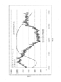
- FIG. 1 shows the daily power transition of the wind power generator of FIG. 1 (variable output due to natural energy) and each leveling target curve for short period and long period varying power.
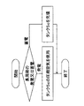
- the flowchart which shows the control method with respect to the long period fluctuation
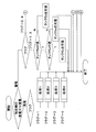
- the flowchart which shows the control method with respect to the short period fluctuation
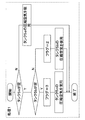
- FIG. 6B is a sub-flowchart relating to process 1 of FIG. 6A.
- FIG. 6B is a sub-flowchart relating to process 2 in FIG. 6A.
- FIG. 6B is a sub-flowchart relating to process 3 of FIG.
- FIG. 6A is a sub-flowchart regarding the process 4 of FIG. 6A.
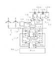
- FIG. 1 shows a schematic block diagram of a compressed air energy storage (CAES) power generator 1 according to a first embodiment of the present invention.
- the CAES power generator 1 is for leveling output fluctuations when generating power using natural energy and for performing output in accordance with fluctuations in power demand.
- the CAES power generation device 1 equalizes the output fluctuation of the wind power generation device 2 (power generation equipment provided with two wind turbines in the first embodiment).
- the CAES power generator 1 includes motors 3a to 3c, compressors 4a to 4c, compressed air storage tanks 5a to 5c, injection side valves 6a to 6e, expanders 7a to 7c, discharge side valves 8a to 8e, and a generator 9a.
- an output sensor 10 pressure sensors 11a to 11c
- the control means 22 includes injection side valves 6a to 6e, discharge side valves 8a to 8e, an output sensor 10, pressure sensors 11a to 11c, and a control device 12.
- the electric power generated by the wind power generator 2 is supplied to motors 3a to 3c that are electrically connected to each other in parallel.
- the motors 3a to 3c are driven by this electric power.
- the motors 3a to 3c are mechanically connected to the compressors 4a to 4c, respectively.
- the compressors 4a to 4c operate by driving the motors 3a to 3c, respectively.
- the compressors 4a to 4c compress the sucked air and send the compressed air to the tanks 5a to 5c. As a result, energy can be stored as compressed air in the tanks 5a to 5c.
- three tanks 5a to 5c are provided.
- the small-capacity tanks 5a and 5b have a capacity capable of storing air or generating power continuously for about 5 to 20 minutes (less than 1 hour).
- the large-capacity tank 5c has a capacity capable of storing or generating power for about 1 to 8 hours (1 hour or more). In order to cope with the fluctuating power generated using wind power or sunlight, it is desirable to set the threshold values of the small capacity tank and the large capacity tank to about 1 hour.
- One motor 3a and 3b and one compressor 4a and 4b are connected to the small capacity tanks 5a and 5b, respectively, via an air supply path.
- All the motors 3a to 3c and the compressors 4a to 4c are connected to the large capacity tank 5c through an air supply path.
- the CAES power generator 1 at least two tanks 5a to 5c having different capacities may be provided. Therefore, for example, the small capacity tanks 5a and 5b may be one or three or more. Two or more large-capacity tanks 5c may be provided. As described above, it is sufficient that at least one small capacity tank 5a, 5b and large capacity tank 5c is provided, and the number is not particularly limited in the second to fifth embodiments described later. It is.
- the small-capacity tanks 5a and 5b do not have to have the same capacity, and when the tank 5a is preferentially controlled as will be described later, the tank 5a can have a smaller capacity than the tank 5b.
- the large-capacity tank 5c may be a salt layer cavity, a closed mine tunnel, an underground cavity such as a sewage pipe / vertical hole, or a bag-like container submerged in water. If the tunnel has good sealing properties, it can be used as the tanks 5a to 5c, and the equipment cost is extremely reduced. In general, in the manufacture of CAES equipment, the cause of the increase in cost is often the manufacture of a large-capacity tank 5c. Therefore, by using a well-sealed tunnel as an alternative to the large-capacity tank 5c, the equipment cost can be greatly reduced. Even in the case of using a closed mine tunnel as a small capacity tank 5a, 5b as well as the large capacity tank 5c, it is also effective for cost reduction. Moreover, it can also be expected as an effective utilization measure of a tunnel (or abandoned tunnel) that requires maintenance costs for many years for appropriate maintenance.
- Injection side valves 6a to 6e are provided in the air supply path between the compressors 4a to 4c and the tanks 5a to 5c. By the injection side valves 6a to 6e, the tanks 5a to 5c to be supplied with compressed air are switched from the compressors 4a to 4c.
- the small-capacity tanks 5a and 5b are connected to the expanders 7a and 7b and the generators 9a and 9b, respectively, through air supply paths.
- the large capacity tank 5c is connected to all of the expanders 7a to 7c and the generators 9a to 9c through an air supply path.
- Compressed air accumulated in the tanks 5a to 5c is supplied to the expanders 7a to 7c.
- the expanders 7a to 7c are driven by the compressed air.
- Discharge-side valves 8a to 8e are provided in the air supply path between the tanks 5a to 5c and the expanders 7a to 7c. By these discharge side valves 8a to 8e, it is switched to which of the expanders 7a to 7c the compressed air is supplied from the respective tanks 5a to 5c.
- the expanders 7a to 7c are electrically connected to each other in parallel, and are mechanically connected to the generators 9a to 9c, respectively.
- the generators 9a to 9c operate by driving the expanders 7a to 7c to generate electric power.
- the output sensor 10 measures the output of the wind power generator 2. You may measure the electric power etc. in the input part of the CAES power generator 1, and may receive it from the wind power generator 2 as an output signal.
- the pressure sensors 11a to 11c measure the pressures in the tanks 5a to 5c, respectively.
- the control device 12 is electrically connected to the injection side valves 6a to 6e and the discharge side valves 8a to 8e. The controller 12 controls the opening and closing of the injection side valves 6a to 6e and the discharge side valves 8a to 8e based on the measured values of the output sensor 10 and the pressure sensors 11a to 11c.
- power devices such as a transformer, an inverter, a relay, and a circuit breaker are arranged between the wind power generator 2 and the motors 3a to 3c and between the system and the generators 9a to 9c.
- the pressure sensors 11a to 11c are used.
- any detector other than the pressure sensor may be provided as long as the remaining amount of air in the tank can be detected.
- the compressors 4a to 4c and the expanders 7a to 7c in the first embodiment may have the same capacity, or the compressor 4c> the compressor 4b> the compressor 4a, the expander 7c> the expander.
- the size may be changed in the order of 7b> expander 7a.
- the smaller the capacity the better the response of the compressor / expander, and the higher the capacity, the higher the efficiency.
- Use of an expander / expander is preferred.
- the CAES power generator 1 uses energy from compressed air. Therefore, it is effective in that it does not discharge environmentally harmful substances. Also, no secondary battery or capacitor is used for energy storage. Secondary batteries and capacitors have disadvantages in use. The secondary battery has a high disposal cost and a short cycle life (number of charge / discharge cycles). Depending on the type, charging rate, voltage monitoring, and temperature management are required. Capacitors have low energy density and are expensive.
- FIG. 2 shows a daily transition example of the output fluctuation of the wind power generator 2 (fluctuating output due to natural energy) and two curves (a long-period demand curve and a short-period reference curve) targeted for leveling.
- the output fluctuation of the wind power generator 2 is measured by the output sensor 10 and recognized by the control device 12 by distinguishing between long-period fluctuation and short-period fluctuation.
- a long cycle indicates a change in units of several hours
- a short cycle indicates a change in units of minutes. Variations in seconds are removed by a filter or the like.
- Short cycle fluctuations are leveled mainly using the small-capacity tanks 5a and 5b.
- FIG. 3 is a flowchart showing a control method for long-period fluctuation.
- the expander 7c is driven using the compressed air in the large capacity tank 5c to generate power.
- the discharge side valve 8c is opened.
- the compressor 4c is used to fill the large capacity tank 5c with compressed air.
- the injection side valve 6c is opened.
- the compressors 4a and 4b may not be used, but the compressors 4a and 4b may also be used when rapid filling is performed.
- the expanders 7a and 7b may not be used, but the expanders 7a and 7b may be used when the discharge power needs to be increased.
- the control device 12 performs switching between power generation and power storage, and rotation speed control of the compressor / expander. This switching decision is made based on the long-period demand curve of FIG.
- the long-period demand curve is determined based on, for example, the day of the week, weather conditions, or the like based on past power usage data accumulated over many years.
- 4A and 4B are flowcharts showing a control method for short period fluctuations.
- power generation is performed and power storage is performed for short-period fluctuation.
- power storage is performed for short cycle fluctuations, for example, the compressor 4a is used to fill the small capacity tank 5a with compressed air.
- the injection side valve 6a is opened and the injection side valve 6d is closed.
- the control device 12 switches between power generation and power storage for short cycle fluctuations as well as for long cycle fluctuations. This switching determination is made based on the short cycle reference curve indicated by a broken line in FIG.
- the short cycle reference curve is determined based on, for example, an average value in a predetermined time immediately before.
- compressors 4a to 4c and expanders 7a to 7c There are generally two types of compressors 4a to 4c and expanders 7a to 7c: positive displacement type represented by turbo type, screw type, scroll type and rotary type.
- positive displacement type represented by turbo type
- screw type screw type
- scroll type rotary type
- the compressors 4a and 4b and the expanders 7a and 7b connected to the small capacity tanks 5a and 5b are positive displacement type.
- the compressor 4c and the expander 7c connected to the large-capacity tank 5c are preferably positive displacement types.
- the positive displacement type does not decrease the efficiency even at a small flow rate (low rotation speed) compared to the turbo type, so that stable power generation can be performed even when the amount of compressed air stored in the tank is small, and the control range can be expanded.
- the compressors 4a and 4b and the expanders 7a and 7b connected to the small-capacity tanks 5a and 5b level out short-cycle fluctuations, and therefore require good followability. It is.
- the compressors 4a to 4c and the expanders 7a to 7c include screw type compressors (specifically, twin screw type) that are suitable for relatively large volumes among positive displacement types, and An expander is used.
- the compressor 4c and the expander 7c connected to the large capacity tank 5c are both turbo type, while the compressors 4a and 4b and the expander 7a connected to the small capacity tanks 5a and 5b. , 7b may be positive displacement.
- small-capacity positive displacement compressors 4a and 4b, positive displacement expanders 7a and 7b, and tanks 5a and 5b are added to the existing CAES equipment (tank 5c, compressor 4c, and expander 7c). can do.
- the existing CAES equipment is generally a turbo type, and the existing equipment can be used as it is.
- the compressor 4c and the expander 7c connected to the large-capacity tank 5c are mainly intended to cope with long-period fluctuations, so that the turbo type can also be handled.
- small compressors 4a and 4b and expanders 7a and 7b for short-cycle variable power, and use large compressors 5c and expander 7c for long-cycle variable power.
- the small compressors 4a and 4b and the expanders 7a and 7b have better responsiveness to input, so that followability to short cycle fluctuations is improved.
- the control device 12 controls the number of compressors 4a and 4b and the expanders 7a and 7b and rotates them based on the amplitude of the short cycle fluctuation power measured using the output sensor 10. Perform number control. However, when performing rotation speed control, the compressors 4a and 4b and the expanders 7a and 7b need to be positive displacement. For example, regarding the number control, the compressor 4a and the expander 7a connected to the small capacity tank 5a are basically used. However, when the amplitude of the fluctuating power deviates from the short cycle reference curve that is too large to be leveled by the compressor 4a and the expander 7a, the number of operating units is increased (the compressor 4b or the expander 7b is used together). .
- the injection side valves 6a to 6e and the discharge side valves 8a to 8e are controlled in accordance with the operations of the compressors 4a to 4c and the expanders 7a to 7c.
- all the compressors 4a to 4c or all the expanders 7a to 7c may be operated simultaneously. In this way, a broader leveling becomes possible.
- the rotation speeds (outputs) of the compressors 4a to 4c and the expanders 7a to 7c are increased or decreased according to the leveling level, and optimal leveling is performed.
- control device 12 further determines which of the small capacity tanks 5a and 5b is to be used based on the measurement values of the pressure sensors 11a to 11c. 4A and 4B show the control when the small-capacity tank 5a is set as the main tank 5a.
- the small capacity tank 5a when power generation is performed with respect to short cycle fluctuation, if the small capacity tank 5a is a filling amount suitable for power generation, the small capacity tank 5a is used (opening the discharge side valve 8a, Close the discharge valve 8d).
- the small-capacity tank 5a is empty or the filling amount is low and when the filling amount of the small-capacity tank 5b is sufficient, the small-capacity tank 5b is used (the discharge side valve 8b is opened and the discharge side valve 8e is closed).
- the large capacity tank 5c When both the small capacity tanks 5a and 5b are empty or the filling amount is low, and the filling amount of the large capacity tank is sufficient, the large capacity tank 5c is unavoidably used (the discharge side valves 8c to 8c). Open any of e and close the other exhaust valves).
- the large capacity tank 5c may be filled with compressed air with a differential pressure from the large capacity tank 5c.
- the large capacity tank 5c is connected via inter-tank air supply valves 21a and 21b so that compressed air can be supplied to the small capacity tanks 5a and 5b.
- the inter-tank air supply valves 21a and 21b an electromagnetic valve that is controlled to open and close based on a pressure difference between a small capacity tank and a large capacity tank or a differential pressure control valve that automatically opens and closes based on the pressure difference can be used.
- the configuration in which the large-capacity tank 5c is filled with the differential pressure of the small-capacity tanks 5a and 5b is the same in the second to fifth embodiments described later.
- the small capacity tank 5a When accumulating electricity for short cycle fluctuations, if the small capacity tank 5a is not full, the small capacity tank 5a is filled with compressed air (the injection side valve 6a is opened and the injection side valve 6d is closed). When the small capacity tank 5a is full and the small capacity tank 5b is not full, the small capacity tank 5b is filled with compressed air (the injection side valve 6b is opened and the injection side valve 6e is closed). When both the small capacity tanks 5a and 5b are full, the large capacity tank 5c is filled with compressed air (the injection side valve 6c is opened).
- FIGS. 7A to 7D show a control method in which the small-capacity tanks 5a and 5b are alternately used.
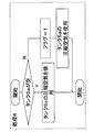
- processing 1 to 4 is selected based on the flag stored by the control device 12.
- the small capacity tank 5a is not empty (or when the amount of compressed air is small; the same applies hereinafter)
- the small capacity tank 5a is used (the discharge side valve 8a is opened and the discharge side valve 8d is closed).
- the flag is changed to 2 and the use of the small capacity tank 5b is started (the discharge side valve 8b is opened and the discharge side valve 8e is closed).
- the flag is changed to 3 and the large capacity tank 5c is used (open one of the discharge side valves 8d and 8e and close the other discharge side valves).
- the small capacity tank 5b is used (the discharge side valve 8b is opened and the discharge side valve 8e is closed).
- the flag is changed to 1, and the use of the small capacity tank 5a is started (the discharge side valve 8a is opened and the discharge side valve 8d is closed).
- the flag is changed to 4 and the large capacity tank 5c is used (open one of the discharge side valves 8d and 8e and close the other discharge side valves. In this case, long The control for the cycle fluctuation is continuously performed by the expander 7c by opening the discharge side valve 8c.)
- the flag is changed to 2 and the small capacity tank 5b is used (the discharge side valve 8b is opened and the discharge side valve 8e is closed).
- the large capacity tank 5c is used (the discharge side valves 8a and 8b are closed and the discharge side valves 8d and / or 8e are opened).
- the tanks 5a to 5c filled with compressed air are selected by the flag stored by the control device 12.
- the small capacity tank 5b is filled with compressed air (the injection side valve 6b is opened and the other valves are closed).
- the small capacity tank 5a is filled with compressed air (the injection side valve 6a is opened and the other valves are closed).
- the large capacity tank 5c is filled with compressed air (open one of the injection side valves 6d and 6e and close the other valves).
- the frequency of use of either of the small capacity tanks 5a and 5b is prevented from increasing. Therefore, it is possible to prevent only one of the small capacity tanks 5a and 5b from being deteriorated in use.
- the main tank 5a is set, even if the small capacity tanks 5a and 5b are all empty, the expanders 7a and 7b are driven using the compressed air of the large capacity tank 5c. Therefore, it is possible to avoid a case where short cycle fluctuations are not leveled.
- a wider range of fluctuations can be smoothed by using both simultaneously.
- a safety valve (not shown) is provided so that the tanks 5a to 5c do not exceed the allowable pressure.
- the safety valve is set in advance to release the compressed air stored in the tanks 5a to 5c to the atmosphere below the allowable pressure when there is a risk of exceeding the allowable pressure.
- the small capacity tanks 5a and 5b may not be used until they are completely emptied.
- the amount of remaining air in the small capacity tanks 5a and 5b decreases, the amount of air supplied to the expanders 7a and 7b decreases, and it may not be possible to secure a sufficient power generation amount.
- a certain threshold value for the remaining air amount in this way, compressed air can be used in a state where an air supply amount (or pressure) above a certain level necessary for power generation is maintained.
- both the long-cycle and short-cycle fluctuation powers are efficiently leveled and the demand power is The corresponding power can be output.
- leveling can be performed even when the small-capacity tanks 5a and 5b are all empty. In order to avoid such a case, it is desirable to fill the differential pressure from the large capacity tank 5c to the small capacity tanks 5a and 5b when the remaining amount of air in the small capacity tanks 5a and 5b decreases.
- FIG. 8 shows the CAES power generator 1 of the second embodiment.
- the CAES power generator 1 of the present embodiment has a configuration other than that relating to the connection of two (plural) compressors 4a, 4b and expanders 7a, 7b to one small capacity tank 5a. This is the same as the first embodiment. Therefore, the same parts as those shown in FIG.
- the CAES power generator 1 of the second embodiment is provided with one small-capacity tank 5a and one large-capacity tank 5b.
- Motors 3a and 3b, compressors 4a and 4b, expanders 7a and 7b, and generators 9a and 9b are connected to the small capacity tank 5a, respectively. All the motors 3a to 3c, the compressors 4a to 4c, the expanders 7a to 7c, and the generators 9a to 9c are connected to the large capacity tank 5b.
- the small capacity tank 5a is compared with the case where only one motor 3a to 3c, compressor 4a to 4c, expander 7a to 7c, and generator 9a to 9c is provided for each tank. Compressed air can accumulate rapidly. Moreover, since only one small-capacity tank is required, the equipment cost and the installation area can be suppressed.
- the second embodiment is the same as the first embodiment in the case where power corresponding to the power demand is output by leveling long-period fluctuations.
- the control device 12 When leveling the short cycle fluctuation, the control device 12 performs the number control and the rotation speed control of the compressors 4a to 4c and the expanders 7a to 7c based on the short cycle reference curve.
- the small capacity tank 5a is filled with compressed air and stored
- one or two compressors 4a and 4b can be used.
- the injection side valves 6a and 6d are opened, and at least the injection side valve 6e is closed.
- two compressors 4a and 4b are used, the injection side valves 6a, 6b, 6d and 6e are opened, and at least the injection side valve 6f is closed.
- the number of compressors 4a and 4b to be used can be adjusted, and the filling speed and filling amount of the compressed air into the small capacity tank 5a can be adjusted.
- one or two of the expanders 7a and 7b can be used.
- the discharge side valves 8a and 8d are opened, and the discharge side valve 8e and other discharge side valves as necessary are closed.
- the discharge side valves 8a, 8b, 8d and 8e are opened, and at least the discharge side valve 8f is closed.
- the amount of power to be generated can be adjusted by adjusting the number of expanders 7a and 7b (generators 9a and 9b) to be used.
- the second embodiment is the same as the first embodiment in the short-period fluctuation leveling method and control other than those described here.
- FIG. 9 shows a CAES power generator 1 according to the third embodiment.
- the CAES power generator 1 of this embodiment is the same as that of the first embodiment of FIG. 1 except for the portion related to the connection configuration of the compressors 4a, 4b and the expanders 7a, 7b to the tanks 5a, 5b. Therefore, the same parts as those shown in FIG.
- the CAES power generator 1 of the third embodiment is provided with one small-capacity tank 5a and one large-capacity tank 5b.
- Motors 3a and 3b, compressors 4a and 4b, expanders 7a and 7b, and generators 9a and 9b are connected to the tanks 5a and 5b, respectively.
- only the compressor 4a and the expander 7a are connected to the small capacity tank 5a.
- Only the compressor 4b and the expander 7b are connected to the large capacity tank 5b. That is, compressed air cannot be supplied from the compressor 4a to the large capacity tank 5b.
- compressed air cannot be supplied to the expander 7a using the large capacity tank 5b.
- the third embodiment is the same as the first embodiment in the case where power corresponding to the power demand is output by leveling long-period fluctuations.
- the control device 12 When leveling the short cycle fluctuation, the control device 12 performs the number control and the rotation speed control of the compressors 4a and 4b and the expanders 7a and 7b based on the short cycle reference curve.
- the small capacity tank 5a When the small capacity tank 5a is filled with compressed air and stored, the compressed air is filled by the compressor 4a (the injection side valve 6a is opened and the other injection side valves are closed).
- the injection side valve 6a is opened and the other injection side valves are closed.
- electric power is generated by the expander 7a and the generator 9a (the discharge side valve 8a is opened and the other discharge side valves are closed).
- the method for leveling short-period fluctuations other than the portions described here is the same as that in the first embodiment.
- FIG. 10 shows a CAES power generator 1 according to the fourth embodiment.
- the CAES power generator 1 of the present embodiment is the same as the first embodiment of FIG. 1 except for the portions related to the heat exchangers 13a to 13d and the heat storage units 14a and 14b. Therefore, the same parts as those shown in FIG.
- the CAES power generator 1 of the fourth embodiment is provided with one small capacity tank 5a and one large capacity tank 5b.
- Motors 3a and 3b, compressors 4a and 4b, expanders 7a and 7b, and generators 9a and 9b are connected to the tanks 5a and 5b, respectively.
- Heat exchangers 13a to 13d and heat storage units 14a and 14b connected to the heat exchangers 13a to 13d are further provided at the entrances and exits of the tanks 5a and 5b, respectively.
- the air compressed by the compressor 4a is heat-recovered (heat absorbed) by the heat medium in the inlet-side heat exchanger 13a before being supplied to the small-capacity tank 5a.
- the heat medium that has absorbed heat by heat exchange in the inlet side heat exchanger 13a is supplied to the heat storage unit 14a by the pump 15a and stored.
- the heat stored in the heat storage unit 14a is returned to the compressed air discharged from the small capacity tank 5a and supplied to the expander 7a via the outlet side heat exchanger 13b.
- heat is recovered (absorbed) by the heat medium in the inlet side heat exchanger 13c.
- the heat medium that has absorbed heat in the inlet-side heat exchanger 13c is supplied to the heat storage unit 14b by the pump 15b and stored.
- the heat stored in the heat storage unit 14b is returned to the compressed air discharged from the small capacity tank 5b and supplied to the expander 7b via the outlet side heat exchanger 13d.
- the heat generated in the compressors 4a and 4b can be recovered before being supplied to the tanks 5a and 5b, and returned to the compressed air supplied to the expanders 7a and 7b, thereby improving the charge / discharge efficiency. That is, energy loss due to heat release of compressed air in each tank 5a, 5b can be prevented and energy efficiency can be improved.
- both the long-period fluctuation and the short-period fluctuation are the same as those in the third embodiment.
- a heating mechanism may be further provided at the outlet of each tank 5a, 5b.
- the charge / discharge efficiency can be improved by heating the air immediately before expansion.
- the lost energy can be recovered by adding heat energy to the compressed air that has been released from the tank and lost energy by heating from the heating mechanism.
- the exhaust heat can be used effectively.
- a plurality of small capacity tanks may be provided as in the first embodiment.
- FIG. 11 shows a CAES power generator 1 according to the fifth embodiment.
- the CAES power generator 1 of the present embodiment is the same as the first embodiment of FIG. 1 except for the portions related to the steam-driven generator 16 and the binary generator 17. Therefore, the same parts as those shown in FIG.
- the CAES power generator 1 of the fifth embodiment is provided with one small-capacity tank 5a and one large-capacity tank 5b.
- Motors 3a and 3b, compressors 4a and 4b, expanders 7a and 7b, and generators 9a and 9b are connected to the tanks 5a and 5b, respectively.
- the steam-driven generator 16 generator 9c that receives steam from another steam source 18 to generate power and the generator 9d of the binary power generation system 17 Four generators 9a to 9d are provided.
- the 11 receives the steam generated from the steam source 18 and generates power. At this time, the steam generated from the steam source 18 is separated in moisture by the drain separator 19 and supplied to the steam-driven generator 16. The electric power generated by the steam driven generator 16 is supplied to a system (not shown) together with the electric power generated by the CAES power generator 1.
- the binary power generation system 17 is a power generation method in which a medium having a low boiling point is heated and evaporated by a heating source, and the turbine is rotated with the steam.
- a medium having a low boiling point for example, an organic substance such as pentane or isobutane, and alternative chlorofluorocarbon or a mixture of ammonia and water are used.
- the steam (for example, about 120 ° C.) after driving the steam generator 16 exchanges heat with a medium having a low boiling point by the heat exchanger 13a.
- the medium having a low boiling point is evaporated by the heat obtained by the heat exchanger 13a, and this steam is supplied to the expander 7d connected to the generator 9d to generate power.
- the steam expanded by the expander 7d is absorbed by the heat exchanger 13b and condensed.
- the condensed medium having a low boiling point is supplied to the heat exchanger 13a by the pump 15a.
- the cooling water exchanged with the medium having a low boiling point by the heat exchanger 13b is supplied to the cooling tower 20 and cooled.
- the cooled cooling water is supplied to the heat exchanger 13b by the pump 15b.
- the output of the wind power generation device 2 can be reliably maintained even when it is excessively unstable unexpectedly, such as when it is stopped for a long time, or when it is excessively small.
- both the long-period fluctuation and the short-period fluctuation are the same as those in the third embodiment.
- the number of compressors and expanders is the same, but the number and capacity of the compressors and expanders need not be equal, and the compressor side can be made smaller (or less). It is possible to enlarge (or increase) the expander side and vice versa.
- the target of the power generator 2 by natural energy is wind power, but the CAES power generator 1 of the present invention is not limited to these. Specifically, it targets all those that use energy that is constantly (or repetitively) supplemented by natural forces, such as wind, sunlight, solar heat, wave or tide, running water or tide, and geothermal heat. Is possible. However, it is particularly effective for wind power generation and solar power generation, which fluctuate greatly depending on weather conditions.
- CAES generator Compressed air storage generator
- Wind power generator 3a, 3b, 3c Motor 4a, 4b, 4c Compressor 5a, 5b, 5c Tank 6a, 6b, 6c, 6d, 6e, 6f Injection side valve 7a, 7b, 7c Expander 8a, 8b, 8c, 8d, 8e, 8f Discharge side valve 9a, 9b, 9c Generator 10
Landscapes
- Engineering & Computer Science (AREA)
- Power Engineering (AREA)
- Mechanical Engineering (AREA)
- General Engineering & Computer Science (AREA)
- Life Sciences & Earth Sciences (AREA)
- Sustainable Development (AREA)
- Sustainable Energy (AREA)
- Chemical & Material Sciences (AREA)
- Combustion & Propulsion (AREA)
- Supply And Distribution Of Alternating Current (AREA)
- Wind Motors (AREA)
Priority Applications (3)
| Application Number | Priority Date | Filing Date | Title |
|---|---|---|---|
| CN201580040767.XA CN106879259B (zh) | 2014-07-31 | 2015-07-28 | 压缩空气储藏发电装置及压缩空气储藏发电方法 |
| US15/323,755 US10352310B2 (en) | 2014-07-31 | 2015-07-28 | Compressed air storage and power generation device and compressed air storage and power generation method |
| EP15827858.0A EP3176902B1 (de) | 2014-07-31 | 2015-07-28 | Druckluftspeicherung und stromerzeugungsvorrichtung sowie druckluftspeicherung und stromerzeugungsverfahren |
Applications Claiming Priority (2)
| Application Number | Priority Date | Filing Date | Title |
|---|---|---|---|
| JP2014156756A JP6368577B2 (ja) | 2014-07-31 | 2014-07-31 | 圧縮空気貯蔵発電装置及び圧縮空気貯蔵発電方法 |
| JP2014-156756 | 2014-07-31 |
Publications (1)
| Publication Number | Publication Date |
|---|---|
| WO2016017639A1 true WO2016017639A1 (ja) | 2016-02-04 |
Family
ID=55217539
Family Applications (1)
| Application Number | Title | Priority Date | Filing Date |
|---|---|---|---|
| PCT/JP2015/071374 Ceased WO2016017639A1 (ja) | 2014-07-31 | 2015-07-28 | 圧縮空気貯蔵発電装置及び圧縮空気貯蔵発電方法 |
Country Status (5)
| Country | Link |
|---|---|
| US (1) | US10352310B2 (de) |
| EP (1) | EP3176902B1 (de) |
| JP (1) | JP6368577B2 (de) |
| CN (1) | CN106879259B (de) |
| WO (1) | WO2016017639A1 (de) |
Cited By (3)
| Publication number | Priority date | Publication date | Assignee | Title |
|---|---|---|---|---|
| JP2017141696A (ja) * | 2016-02-08 | 2017-08-17 | 株式会社神戸製鋼所 | 圧縮空気貯蔵発電装置 |
| CN110446839A (zh) * | 2017-03-29 | 2019-11-12 | 株式会社神户制钢所 | 压缩空气储能发电装置 |
| CN110506153A (zh) * | 2017-04-19 | 2019-11-26 | 株式会社神户制钢所 | 压缩空气储能发电装置及压缩空气储能发电方法 |
Families Citing this family (22)
| Publication number | Priority date | Publication date | Assignee | Title |
|---|---|---|---|---|
| JP6510876B2 (ja) * | 2015-05-01 | 2019-05-08 | 株式会社神戸製鋼所 | 圧縮空気貯蔵発電方法および圧縮空気貯蔵発電装置 |
| US10664866B2 (en) * | 2016-11-30 | 2020-05-26 | Facebook, Inc. | Conversion optimization with long attribution window |
| JP6889604B2 (ja) | 2017-04-26 | 2021-06-18 | 株式会社神戸製鋼所 | 圧縮空気貯蔵発電装置 |
| JP6885777B2 (ja) | 2017-04-26 | 2021-06-16 | 株式会社神戸製鋼所 | 圧縮空気貯蔵発電装置 |
| JP2019027384A (ja) * | 2017-08-01 | 2019-02-21 | 株式会社神戸製鋼所 | 圧縮空気貯蔵発電装置 |
| CN107795346B (zh) * | 2017-11-29 | 2023-08-22 | 中国电力工程顾问集团西北电力设计院有限公司 | 碟式储能光热声发电系统 |
| CN108252869A (zh) * | 2018-02-09 | 2018-07-06 | 四川中投亿星新能源科技有限公司 | 一种风力驱动单螺杆压缩机 |
| JP2019213440A (ja) * | 2018-05-30 | 2019-12-12 | 村山 修 | 電気自動車に向かって発生する向かい風を活用して電費が少なく、充電不要の電気自動車 |
| JP7198632B2 (ja) * | 2018-10-31 | 2023-01-04 | 大豊建設株式会社 | 風力発電システム |
| JP7022677B2 (ja) * | 2018-12-14 | 2022-02-18 | 株式会社神戸製鋼所 | 圧縮空気貯蔵発電装置及び圧縮空気貯蔵発電方法 |
| AU2019441003B2 (en) * | 2019-04-18 | 2022-11-24 | Yuan Cherng Hwang | Air-compression energy-storage and power-supply system having air purification capability through using solar energy |
| US11428445B2 (en) * | 2019-09-05 | 2022-08-30 | Gridworthy Technologies LLC | System and method of pumped heat energy storage |
| JP2021076056A (ja) * | 2019-11-07 | 2021-05-20 | 住友重機械工業株式会社 | 発電システム、制御装置及び発電方法 |
| CN111237144A (zh) * | 2020-01-14 | 2020-06-05 | 中国华能集团有限公司 | 一种重力压缩空气储能系统及其工作方法 |
| JP2022173944A (ja) * | 2021-05-10 | 2022-11-22 | 株式会社神戸製鋼所 | 圧縮空気エネルギー貯蔵発電装置及びその制御方法 |
| JP7011748B1 (ja) | 2021-08-26 | 2022-01-27 | 清三 菅 | 移動体用風力発電装置 |
| US20230213149A1 (en) * | 2021-12-31 | 2023-07-06 | Kepler Energy Systems, Inc. | Power Shift System to Store and Distribute Energy |
| CN115199515A (zh) * | 2022-08-12 | 2022-10-18 | 中国科学院工程热物理研究所 | 一种压缩空气储能系统以及多级接力储气方法 |
| CN120677300A (zh) | 2023-05-19 | 2025-09-19 | 株式会社日立产机系统 | 压缩空气储能装置 |
| JP2025063773A (ja) | 2023-10-04 | 2025-04-16 | 株式会社日立産機システム | 圧縮空気エネルギ貯蔵装置 |
| CN117703553B (zh) * | 2024-01-05 | 2024-06-14 | 西南石油大学 | 一种基于闲置油气井储气的耦合地热能压缩空气储能系统 |
| CN118548177A (zh) * | 2024-05-29 | 2024-08-27 | 中国长江三峡集团有限公司 | 面向新能源基地的压储系统及风光储输一体化系统 |
Citations (9)
| Publication number | Priority date | Publication date | Assignee | Title |
|---|---|---|---|---|
| JP2002135979A (ja) * | 2000-10-30 | 2002-05-10 | Toshiba Corp | 自立型ハイブリッド発電システム |
| JP2003083082A (ja) * | 2001-08-17 | 2003-03-19 | Alstom (Switzerland) Ltd | ガス貯蔵発電設備の運転方法 |
| JP2005530074A (ja) * | 2001-10-05 | 2005-10-06 | エニス、ベン | 風力タービンを使って発電した電力を、発電敷設網から遠く離れた場所に中断されることなく供給する方法とそれに関する装置 |
| JP2009525432A (ja) * | 2006-01-31 | 2009-07-09 | エム. エニス,ベン | パイプラインを使用する風力発電エネルギーを輸送し貯蔵する改善された方法 |
| JP2011234563A (ja) * | 2010-04-28 | 2011-11-17 | Toshiba Corp | 蓄電池制御システム及び蓄電池制御方法 |
| JP2012097737A (ja) * | 2010-10-29 | 2012-05-24 | Nuovo Pignone Spa | 先進的断熱圧縮空気エネルギー貯蔵システムの圧縮空気を予熱するシステム及び方法 |
| JP2012239370A (ja) * | 2011-04-13 | 2012-12-06 | Toshiaki Ota | 分散型圧縮空気貯蔵発電システム |
| JP2013509529A (ja) * | 2009-10-28 | 2013-03-14 | ゼネラル・エレクトリック・カンパニイ | 圧縮器−膨張器可逆式ユニットを備える圧縮空気エネルギー貯蔵システム |
| JP2014515339A (ja) * | 2011-05-23 | 2014-06-30 | ストレワット | 流体を貯蔵および送出するためのデバイスならびにかかるデバイス内に収容された圧縮ガスを貯蔵および送出するための方法 |
Family Cites Families (19)
| Publication number | Priority date | Publication date | Assignee | Title |
|---|---|---|---|---|
| US4229661A (en) | 1979-02-21 | 1980-10-21 | Mead Claude F | Power plant for camping trailer |
| JPH07317649A (ja) | 1994-05-27 | 1995-12-05 | Les-Ben:Kk | 太陽光発電装置及びその発電方法 |
| DE20013905U1 (de) * | 2000-08-12 | 2000-12-21 | stryker Trauma GmbH, 24232 Schönkirchen | Hülsenförmige Vorrichtung zum Halten von Schrauben beim Eindrehen in einen Gegenstand, z.B. in einen Knochen, mit Hilfe eines Schraubendrehers |
| US7078083B2 (en) * | 2001-05-29 | 2006-07-18 | Matsushita Electric Industrial Co., Ltd. | Optical recording film, method for manufacturing the same, optical recording medium, information recording/reproducing device, computer system and video signal recording/reproducing system |
| US8478625B2 (en) | 2001-08-17 | 2013-07-02 | Alstom Technology Ltd | Method for operating a gas storage power plant |
| US7308361B2 (en) | 2001-10-05 | 2007-12-11 | Enis Ben M | Method of coordinating and stabilizing the delivery of wind generated energy |
| US6963802B2 (en) | 2001-10-05 | 2005-11-08 | Enis Ben M | Method of coordinating and stabilizing the delivery of wind generated energy |
| US7504739B2 (en) | 2001-10-05 | 2009-03-17 | Enis Ben M | Method of transporting and storing wind generated energy using a pipeline |
| AU2004245952A1 (en) | 2003-05-30 | 2004-12-16 | Ben M. Enis | A method of storing and transporting wind generated energy using a pipeline system |
| US7974742B2 (en) | 2003-06-13 | 2011-07-05 | Enis Ben M | Method of coordinating and stabilizing the delivery of wind generated energy |
| EP1536541A1 (de) | 2003-11-25 | 2005-06-01 | Alstom Technology Ltd | Anlage und Verfahren zur Nutzung regenerativer Energieformen mit nichtsteuerbarer Leistungsverfügbarkeit |
| US7619270B2 (en) * | 2005-07-25 | 2009-11-17 | Freescale Semiconductor, Inc. | Electronic device including discontinuous storage elements |
| EP2514417A3 (de) * | 2007-05-07 | 2013-01-30 | Chelsea Therapeutics, Inc. | Droxidopa und pharmazeutische Zusammensetzung davon, zur Behandlung von Stimmungsstörungen, Schlafstörungen oder Aufmerksamkeitsdefizit-Störungen |
| US20110009421A1 (en) * | 2008-02-27 | 2011-01-13 | Takeda Pharmaceutical Company Limited | Compound having 6-membered aromatic ring |
| US7832207B2 (en) * | 2008-04-09 | 2010-11-16 | Sustainx, Inc. | Systems and methods for energy storage and recovery using compressed gas |
| AU2009265720B2 (en) * | 2008-06-30 | 2011-12-08 | Vestas Wind Systems A/S | A method of controlling a wind power plant |
| US8347628B2 (en) * | 2009-08-18 | 2013-01-08 | Gerard Henry M | Power generation directly from compressed air for exploiting wind and solar power |
| KR101754799B1 (ko) * | 2010-03-26 | 2017-07-07 | 삼성전자주식회사 | 화소 회로, 이를 포함하는 디스플레이 장치 및 디스플레이 장치의 구동방법 |
| CN108318843B (zh) * | 2011-09-22 | 2021-11-16 | 东芝医疗系统株式会社 | 磁共振成像装置以及磁共振成像方法 |
-
2014
- 2014-07-31 JP JP2014156756A patent/JP6368577B2/ja not_active Expired - Fee Related
-
2015
- 2015-07-28 US US15/323,755 patent/US10352310B2/en active Active
- 2015-07-28 WO PCT/JP2015/071374 patent/WO2016017639A1/ja not_active Ceased
- 2015-07-28 CN CN201580040767.XA patent/CN106879259B/zh not_active Expired - Fee Related
- 2015-07-28 EP EP15827858.0A patent/EP3176902B1/de active Active
Patent Citations (9)
| Publication number | Priority date | Publication date | Assignee | Title |
|---|---|---|---|---|
| JP2002135979A (ja) * | 2000-10-30 | 2002-05-10 | Toshiba Corp | 自立型ハイブリッド発電システム |
| JP2003083082A (ja) * | 2001-08-17 | 2003-03-19 | Alstom (Switzerland) Ltd | ガス貯蔵発電設備の運転方法 |
| JP2005530074A (ja) * | 2001-10-05 | 2005-10-06 | エニス、ベン | 風力タービンを使って発電した電力を、発電敷設網から遠く離れた場所に中断されることなく供給する方法とそれに関する装置 |
| JP2009525432A (ja) * | 2006-01-31 | 2009-07-09 | エム. エニス,ベン | パイプラインを使用する風力発電エネルギーを輸送し貯蔵する改善された方法 |
| JP2013509529A (ja) * | 2009-10-28 | 2013-03-14 | ゼネラル・エレクトリック・カンパニイ | 圧縮器−膨張器可逆式ユニットを備える圧縮空気エネルギー貯蔵システム |
| JP2011234563A (ja) * | 2010-04-28 | 2011-11-17 | Toshiba Corp | 蓄電池制御システム及び蓄電池制御方法 |
| JP2012097737A (ja) * | 2010-10-29 | 2012-05-24 | Nuovo Pignone Spa | 先進的断熱圧縮空気エネルギー貯蔵システムの圧縮空気を予熱するシステム及び方法 |
| JP2012239370A (ja) * | 2011-04-13 | 2012-12-06 | Toshiaki Ota | 分散型圧縮空気貯蔵発電システム |
| JP2014515339A (ja) * | 2011-05-23 | 2014-06-30 | ストレワット | 流体を貯蔵および送出するためのデバイスならびにかかるデバイス内に収容された圧縮ガスを貯蔵および送出するための方法 |
Non-Patent Citations (1)
| Title |
|---|
| See also references of EP3176902A4 * |
Cited By (3)
| Publication number | Priority date | Publication date | Assignee | Title |
|---|---|---|---|---|
| JP2017141696A (ja) * | 2016-02-08 | 2017-08-17 | 株式会社神戸製鋼所 | 圧縮空気貯蔵発電装置 |
| CN110446839A (zh) * | 2017-03-29 | 2019-11-12 | 株式会社神户制钢所 | 压缩空气储能发电装置 |
| CN110506153A (zh) * | 2017-04-19 | 2019-11-26 | 株式会社神户制钢所 | 压缩空气储能发电装置及压缩空气储能发电方法 |
Also Published As
| Publication number | Publication date |
|---|---|
| US10352310B2 (en) | 2019-07-16 |
| EP3176902A4 (de) | 2018-03-21 |
| JP2016034211A (ja) | 2016-03-10 |
| EP3176902A1 (de) | 2017-06-07 |
| CN106879259B (zh) | 2020-06-26 |
| JP6368577B2 (ja) | 2018-08-01 |
| CN106879259A (zh) | 2017-06-20 |
| US20170159649A1 (en) | 2017-06-08 |
| EP3176902B1 (de) | 2021-06-30 |
Similar Documents
| Publication | Publication Date | Title |
|---|---|---|
| JP6368577B2 (ja) | 圧縮空気貯蔵発電装置及び圧縮空気貯蔵発電方法 | |
| CN107532510B (zh) | 压缩空气储能发电方法及压缩空气储能发电装置 | |
| CN107532511B (zh) | 压缩空气储藏发电装置以及压缩空气储藏发电方法 | |
| CN107534315B (zh) | 压缩空气储能发电方法及压缩空气储能发电装置 | |
| US10746097B2 (en) | Compressed air energy storage power generation device and compressed air energy storage power generation method | |
| US20200325891A1 (en) | Compressed air energy storage generator | |
| EP3372804B1 (de) | Vorrichtung und verfahren zur erzeugung von energie aus druckluftspeichern | |
| US10868440B2 (en) | Compressed air energy storage generator | |
| US20220006321A1 (en) | Compressed air energy storage and power generation apparatus and compressed air energy storage and power generation method |
Legal Events
| Date | Code | Title | Description |
|---|---|---|---|
| 121 | Ep: the epo has been informed by wipo that ep was designated in this application |
Ref document number: 15827858 Country of ref document: EP Kind code of ref document: A1 |
|
| WWE | Wipo information: entry into national phase |
Ref document number: 15323755 Country of ref document: US |
|
| REEP | Request for entry into the european phase |
Ref document number: 2015827858 Country of ref document: EP |
|
| WWE | Wipo information: entry into national phase |
Ref document number: 2015827858 Country of ref document: EP |
|
| NENP | Non-entry into the national phase |
Ref country code: DE |