WO2016017691A1 - Article moulé formant film, corps emballé dans ledit film, procédé de fabrication d'article moulé formant film et procédé de fabrication de corps emballé dans ledit film - Google Patents
Article moulé formant film, corps emballé dans ledit film, procédé de fabrication d'article moulé formant film et procédé de fabrication de corps emballé dans ledit film Download PDFInfo
- Publication number
- WO2016017691A1 WO2016017691A1 PCT/JP2015/071501 JP2015071501W WO2016017691A1 WO 2016017691 A1 WO2016017691 A1 WO 2016017691A1 JP 2015071501 W JP2015071501 W JP 2015071501W WO 2016017691 A1 WO2016017691 A1 WO 2016017691A1
- Authority
- WO
- WIPO (PCT)
- Prior art keywords
- film
- shape
- molded body
- embossed
- package
- Prior art date
- Legal status (The legal status is an assumption and is not a legal conclusion. Google has not performed a legal analysis and makes no representation as to the accuracy of the status listed.)
- Ceased
Links
Images











Classifications
-
- B—PERFORMING OPERATIONS; TRANSPORTING
- B65—CONVEYING; PACKING; STORING; HANDLING THIN OR FILAMENTARY MATERIAL
- B65D—CONTAINERS FOR STORAGE OR TRANSPORT OF ARTICLES OR MATERIALS, e.g. BAGS, BARRELS, BOTTLES, BOXES, CANS, CARTONS, CRATES, DRUMS, JARS, TANKS, HOPPERS, FORWARDING CONTAINERS; ACCESSORIES, CLOSURES, OR FITTINGS THEREFOR; PACKAGING ELEMENTS; PACKAGES
- B65D71/00—Bundles of articles held together by packaging elements for convenience of storage or transport, e.g. portable segregating carrier for plural receptacles such as beer cans or pop bottles; Bales of material
- B65D71/06—Packaging elements holding or encircling completely or almost completely the bundle of articles, e.g. wrappers
- B65D71/08—Wrappers shrunk by heat or under tension, e.g. stretch films or films tensioned by compressed articles
- B65D71/10—Wrappers shrunk by heat or under tension, e.g. stretch films or films tensioned by compressed articles and provided with inserts
-
- B—PERFORMING OPERATIONS; TRANSPORTING
- B21—MECHANICAL METAL-WORKING WITHOUT ESSENTIALLY REMOVING MATERIAL; PUNCHING METAL
- B21D—WORKING OR PROCESSING OF SHEET METAL OR METAL TUBES, RODS OR PROFILES WITHOUT ESSENTIALLY REMOVING MATERIAL; PUNCHING METAL
- B21D22/00—Shaping without cutting, by stamping, spinning, or deep-drawing
- B21D22/02—Stamping using rigid devices or tools
- B21D22/04—Stamping using rigid devices or tools for dimpling
-
- B—PERFORMING OPERATIONS; TRANSPORTING
- B21—MECHANICAL METAL-WORKING WITHOUT ESSENTIALLY REMOVING MATERIAL; PUNCHING METAL
- B21D—WORKING OR PROCESSING OF SHEET METAL OR METAL TUBES, RODS OR PROFILES WITHOUT ESSENTIALLY REMOVING MATERIAL; PUNCHING METAL
- B21D33/00—Special measures in connection with working metal foils, e.g. gold foils
-
- B—PERFORMING OPERATIONS; TRANSPORTING
- B29—WORKING OF PLASTICS; WORKING OF SUBSTANCES IN A PLASTIC STATE IN GENERAL
- B29C—SHAPING OR JOINING OF PLASTICS; SHAPING OF MATERIAL IN A PLASTIC STATE, NOT OTHERWISE PROVIDED FOR; AFTER-TREATMENT OF THE SHAPED PRODUCTS, e.g. REPAIRING
- B29C51/00—Shaping by thermoforming, i.e. shaping sheets or sheet like preforms after heating, e.g. shaping sheets in matched moulds or by deep-drawing; Apparatus therefor
- B29C51/08—Deep drawing or matched-mould forming, i.e. using mechanical means only
-
- B—PERFORMING OPERATIONS; TRANSPORTING
- B29—WORKING OF PLASTICS; WORKING OF SUBSTANCES IN A PLASTIC STATE IN GENERAL
- B29C—SHAPING OR JOINING OF PLASTICS; SHAPING OF MATERIAL IN A PLASTIC STATE, NOT OTHERWISE PROVIDED FOR; AFTER-TREATMENT OF THE SHAPED PRODUCTS, e.g. REPAIRING
- B29C51/00—Shaping by thermoforming, i.e. shaping sheets or sheet like preforms after heating, e.g. shaping sheets in matched moulds or by deep-drawing; Apparatus therefor
- B29C51/10—Forming by pressure difference, e.g. vacuum
-
- B—PERFORMING OPERATIONS; TRANSPORTING
- B29—WORKING OF PLASTICS; WORKING OF SUBSTANCES IN A PLASTIC STATE IN GENERAL
- B29C—SHAPING OR JOINING OF PLASTICS; SHAPING OF MATERIAL IN A PLASTIC STATE, NOT OTHERWISE PROVIDED FOR; AFTER-TREATMENT OF THE SHAPED PRODUCTS, e.g. REPAIRING
- B29C51/00—Shaping by thermoforming, i.e. shaping sheets or sheet like preforms after heating, e.g. shaping sheets in matched moulds or by deep-drawing; Apparatus therefor
- B29C51/14—Shaping by thermoforming, i.e. shaping sheets or sheet like preforms after heating, e.g. shaping sheets in matched moulds or by deep-drawing; Apparatus therefor using multilayered preforms or sheets
-
- B—PERFORMING OPERATIONS; TRANSPORTING
- B29—WORKING OF PLASTICS; WORKING OF SUBSTANCES IN A PLASTIC STATE IN GENERAL
- B29C—SHAPING OR JOINING OF PLASTICS; SHAPING OF MATERIAL IN A PLASTIC STATE, NOT OTHERWISE PROVIDED FOR; AFTER-TREATMENT OF THE SHAPED PRODUCTS, e.g. REPAIRING
- B29C59/00—Surface shaping of articles, e.g. embossing; Apparatus therefor
- B29C59/02—Surface shaping of articles, e.g. embossing; Apparatus therefor by mechanical means, e.g. pressing
- B29C59/026—Surface shaping of articles, e.g. embossing; Apparatus therefor by mechanical means, e.g. pressing of layered or coated substantially flat surfaces
-
- B—PERFORMING OPERATIONS; TRANSPORTING
- B65—CONVEYING; PACKING; STORING; HANDLING THIN OR FILAMENTARY MATERIAL
- B65D—CONTAINERS FOR STORAGE OR TRANSPORT OF ARTICLES OR MATERIALS, e.g. BAGS, BARRELS, BOTTLES, BOXES, CANS, CARTONS, CRATES, DRUMS, JARS, TANKS, HOPPERS, FORWARDING CONTAINERS; ACCESSORIES, CLOSURES, OR FITTINGS THEREFOR; PACKAGING ELEMENTS; PACKAGES
- B65D75/00—Packages comprising articles or materials partially or wholly enclosed in strips, sheets, blanks, tubes or webs of flexible sheet material, e.g. in folded wrappers
- B65D75/002—Packages comprising articles or materials partially or wholly enclosed in strips, sheets, blanks, tubes or webs of flexible sheet material, e.g. in folded wrappers in shrink films
-
- B—PERFORMING OPERATIONS; TRANSPORTING
- B65—CONVEYING; PACKING; STORING; HANDLING THIN OR FILAMENTARY MATERIAL
- B65D—CONTAINERS FOR STORAGE OR TRANSPORT OF ARTICLES OR MATERIALS, e.g. BAGS, BARRELS, BOTTLES, BOXES, CANS, CARTONS, CRATES, DRUMS, JARS, TANKS, HOPPERS, FORWARDING CONTAINERS; ACCESSORIES, CLOSURES, OR FITTINGS THEREFOR; PACKAGING ELEMENTS; PACKAGES
- B65D75/00—Packages comprising articles or materials partially or wholly enclosed in strips, sheets, blanks, tubes or webs of flexible sheet material, e.g. in folded wrappers
- B65D75/04—Articles or materials wholly enclosed in single sheets or wrapper blanks
- B65D75/06—Articles or materials wholly enclosed in single sheets or wrapper blanks in sheets or blanks initially folded to form tubes
- B65D75/12—Articles or materials wholly enclosed in single sheets or wrapper blanks in sheets or blanks initially folded to form tubes with the ends of the tube closed by flattening and heat-sealing
-
- B—PERFORMING OPERATIONS; TRANSPORTING
- B65—CONVEYING; PACKING; STORING; HANDLING THIN OR FILAMENTARY MATERIAL
- B65D—CONTAINERS FOR STORAGE OR TRANSPORT OF ARTICLES OR MATERIALS, e.g. BAGS, BARRELS, BOTTLES, BOXES, CANS, CARTONS, CRATES, DRUMS, JARS, TANKS, HOPPERS, FORWARDING CONTAINERS; ACCESSORIES, CLOSURES, OR FITTINGS THEREFOR; PACKAGING ELEMENTS; PACKAGES
- B65D75/00—Packages comprising articles or materials partially or wholly enclosed in strips, sheets, blanks, tubes or webs of flexible sheet material, e.g. in folded wrappers
- B65D75/04—Articles or materials wholly enclosed in single sheets or wrapper blanks
- B65D75/20—Articles or materials wholly enclosed in single sheets or wrapper blanks in sheets or blanks doubled around contents and having their opposed free margins united, e.g. by pressure-sensitive adhesive, crimping, heat-sealing, or welding
-
- B—PERFORMING OPERATIONS; TRANSPORTING
- B65—CONVEYING; PACKING; STORING; HANDLING THIN OR FILAMENTARY MATERIAL
- B65D—CONTAINERS FOR STORAGE OR TRANSPORT OF ARTICLES OR MATERIALS, e.g. BAGS, BARRELS, BOTTLES, BOXES, CANS, CARTONS, CRATES, DRUMS, JARS, TANKS, HOPPERS, FORWARDING CONTAINERS; ACCESSORIES, CLOSURES, OR FITTINGS THEREFOR; PACKAGING ELEMENTS; PACKAGES
- B65D75/00—Packages comprising articles or materials partially or wholly enclosed in strips, sheets, blanks, tubes or webs of flexible sheet material, e.g. in folded wrappers
- B65D75/28—Articles or materials wholly enclosed in composite wrappers, i.e. wrappers formed by associating or interconnecting two or more sheets or blanks
- B65D75/30—Articles or materials enclosed between two opposed sheets or blanks having their margins united, e.g. by pressure-sensitive adhesive, crimping, heat-sealing, or welding
-
- H—ELECTRICITY
- H01—ELECTRIC ELEMENTS
- H01M—PROCESSES OR MEANS, e.g. BATTERIES, FOR THE DIRECT CONVERSION OF CHEMICAL ENERGY INTO ELECTRICAL ENERGY
- H01M50/00—Constructional details or processes of manufacture of the non-active parts of electrochemical cells other than fuel cells, e.g. hybrid cells
- H01M50/10—Primary casings; Jackets or wrappings
- H01M50/102—Primary casings; Jackets or wrappings characterised by their shape or physical structure
-
- H—ELECTRICITY
- H01—ELECTRIC ELEMENTS
- H01M—PROCESSES OR MEANS, e.g. BATTERIES, FOR THE DIRECT CONVERSION OF CHEMICAL ENERGY INTO ELECTRICAL ENERGY
- H01M50/00—Constructional details or processes of manufacture of the non-active parts of electrochemical cells other than fuel cells, e.g. hybrid cells
- H01M50/10—Primary casings; Jackets or wrappings
- H01M50/102—Primary casings; Jackets or wrappings characterised by their shape or physical structure
- H01M50/105—Pouches or flexible bags
-
- H—ELECTRICITY
- H01—ELECTRIC ELEMENTS
- H01M—PROCESSES OR MEANS, e.g. BATTERIES, FOR THE DIRECT CONVERSION OF CHEMICAL ENERGY INTO ELECTRICAL ENERGY
- H01M50/00—Constructional details or processes of manufacture of the non-active parts of electrochemical cells other than fuel cells, e.g. hybrid cells
- H01M50/10—Primary casings; Jackets or wrappings
- H01M50/116—Primary casings; Jackets or wrappings characterised by the material
- H01M50/124—Primary casings; Jackets or wrappings characterised by the material having a layered structure
-
- H—ELECTRICITY
- H01—ELECTRIC ELEMENTS
- H01M—PROCESSES OR MEANS, e.g. BATTERIES, FOR THE DIRECT CONVERSION OF CHEMICAL ENERGY INTO ELECTRICAL ENERGY
- H01M50/00—Constructional details or processes of manufacture of the non-active parts of electrochemical cells other than fuel cells, e.g. hybrid cells
- H01M50/10—Primary casings; Jackets or wrappings
- H01M50/138—Primary casings; Jackets or wrappings adapted for specific cells, e.g. electrochemical cells operating at high temperature
-
- B—PERFORMING OPERATIONS; TRANSPORTING
- B29—WORKING OF PLASTICS; WORKING OF SUBSTANCES IN A PLASTIC STATE IN GENERAL
- B29K—INDEXING SCHEME ASSOCIATED WITH SUBCLASSES B29B, B29C OR B29D, RELATING TO MOULDING MATERIALS OR TO MATERIALS FOR MOULDS, REINFORCEMENTS, FILLERS OR PREFORMED PARTS, e.g. INSERTS
- B29K2023/00—Use of polyalkenes or derivatives thereof as moulding material
- B29K2023/10—Polymers of propylene
- B29K2023/12—PP, i.e. polypropylene
-
- B—PERFORMING OPERATIONS; TRANSPORTING
- B29—WORKING OF PLASTICS; WORKING OF SUBSTANCES IN A PLASTIC STATE IN GENERAL
- B29K—INDEXING SCHEME ASSOCIATED WITH SUBCLASSES B29B, B29C OR B29D, RELATING TO MOULDING MATERIALS OR TO MATERIALS FOR MOULDS, REINFORCEMENTS, FILLERS OR PREFORMED PARTS, e.g. INSERTS
- B29K2077/00—Use of PA, i.e. polyamides, e.g. polyesteramides or derivatives thereof, as moulding material
-
- B—PERFORMING OPERATIONS; TRANSPORTING
- B29—WORKING OF PLASTICS; WORKING OF SUBSTANCES IN A PLASTIC STATE IN GENERAL
- B29K—INDEXING SCHEME ASSOCIATED WITH SUBCLASSES B29B, B29C OR B29D, RELATING TO MOULDING MATERIALS OR TO MATERIALS FOR MOULDS, REINFORCEMENTS, FILLERS OR PREFORMED PARTS, e.g. INSERTS
- B29K2705/00—Use of metals, their alloys or their compounds, for preformed parts, e.g. for inserts
-
- B—PERFORMING OPERATIONS; TRANSPORTING
- B29—WORKING OF PLASTICS; WORKING OF SUBSTANCES IN A PLASTIC STATE IN GENERAL
- B29K—INDEXING SCHEME ASSOCIATED WITH SUBCLASSES B29B, B29C OR B29D, RELATING TO MOULDING MATERIALS OR TO MATERIALS FOR MOULDS, REINFORCEMENTS, FILLERS OR PREFORMED PARTS, e.g. INSERTS
- B29K2705/00—Use of metals, their alloys or their compounds, for preformed parts, e.g. for inserts
- B29K2705/02—Aluminium
-
- B—PERFORMING OPERATIONS; TRANSPORTING
- B29—WORKING OF PLASTICS; WORKING OF SUBSTANCES IN A PLASTIC STATE IN GENERAL
- B29L—INDEXING SCHEME ASSOCIATED WITH SUBCLASS B29C, RELATING TO PARTICULAR ARTICLES
- B29L2031/00—Other particular articles
- B29L2031/712—Containers; Packaging elements or accessories, Packages
-
- B—PERFORMING OPERATIONS; TRANSPORTING
- B29—WORKING OF PLASTICS; WORKING OF SUBSTANCES IN A PLASTIC STATE IN GENERAL
- B29L—INDEXING SCHEME ASSOCIATED WITH SUBCLASS B29C, RELATING TO PARTICULAR ARTICLES
- B29L2031/00—Other particular articles
- B29L2031/712—Containers; Packaging elements or accessories, Packages
- B29L2031/7162—Boxes, cartons, cases
-
- Y—GENERAL TAGGING OF NEW TECHNOLOGICAL DEVELOPMENTS; GENERAL TAGGING OF CROSS-SECTIONAL TECHNOLOGIES SPANNING OVER SEVERAL SECTIONS OF THE IPC; TECHNICAL SUBJECTS COVERED BY FORMER USPC CROSS-REFERENCE ART COLLECTIONS [XRACs] AND DIGESTS
- Y02—TECHNOLOGIES OR APPLICATIONS FOR MITIGATION OR ADAPTATION AGAINST CLIMATE CHANGE
- Y02E—REDUCTION OF GREENHOUSE GAS [GHG] EMISSIONS, RELATED TO ENERGY GENERATION, TRANSMISSION OR DISTRIBUTION
- Y02E60/00—Enabling technologies; Technologies with a potential or indirect contribution to GHG emissions mitigation
- Y02E60/10—Energy storage using batteries
Definitions
- the present invention relates to a film molded body, a film package using the film molded body, a method for producing the film molded body, and a method for producing the film package.
- a film material made of a laminate film, a metal foil, or the like has been used for a package of each product such as cosmetics, an exterior body of a lithium ion secondary battery, or the like (for example, see Patent Documents 1 and 2). reference).
- a film material made of a laminate film, a metal foil, or the like has been used for a package of each product such as cosmetics, an exterior body of a lithium ion secondary battery, or the like (for example, see Patent Documents 1 and 2). reference).
- the periphery of each film material is placed under a reduced pressure environment after the packaged object is sandwiched between a pair of film materials.
- a method is employed in which the parts are sealed by a method such as adhesion or heat sealing.
- Patent Document 3 A method of forming a recess for accommodating has been proposed (see, for example, Patent Document 3).
- Patent Document 3 As in the technique described in Patent Document 3, by forming the recesses in the film material in advance, an effect of improving productivity when packaging the battery cells with the film material can be obtained.
- Patent Document 3 in order to form a recess corresponding to the overall shape such as the size of the battery cell for accommodating the battery cell, the manufacturing equipment such as a mold to be used is also large. Therefore, there is a problem that the manufacturing cost increases.
- the packaged object when packaging the above-described packaged object, the packaged object is wrapped in a flat sheet form without forming a recess or the like in the film material, and in this state, the peripheral part is sealed under a reduced pressure environment. It is also considered to make a laminated film package by stopping. In this way, it is not necessary to use a large and expensive manufacturing facility by packaging a package object using the film material in the form of a flat sheet. Moreover, since the process of forming the recessed part corresponding to the shape of the whole to-be-packaged object can be omitted, the effect that productivity is improved is obtained.
- the film material starts from the vicinity of the edge of the accommodation portion of the package. Wrinkles may occur.
- the larger the thickness of the article to be packaged the easier it is for wrinkles to be formed (see, for example, FIG. 16C). Since such a ridge is formed so as to extend from the vicinity of the edge toward the peripheral portion of the film material, since air enters the portion of the ridge, the sealing performance may be lowered. .
- the sealing performance by the film material is lowered, for example, when a battery cell is used as an object to be packaged, there is a possibility that the battery characteristic may be lowered and the appearance characteristic is also lowered. .
- the present invention has been made in view of the above problems, and a film molded body capable of suppressing wrinkles on a film when a packaged object is packaged and sealed, and a film using the same Provided are a package, a method for producing a molded film, and a method for producing a film package.
- Invention of Claim 1 is a film molded object, Comprising: The concave or convex embossed part each arranged in plurality spaced apart is formed in the surface of a film, The plurality of embossed parts are, In the surface of the said film, it is arrange
- the embossed part is semicircle shape, a triangle shape, U shape, a linear shape, a polygonal line shape, a curve shape by planar view, It is a quadrangular shape, a circular shape, or a dot shape.
- the embossed portion has the above shape, so that the surrounding region can be secured with a stable shape. Moreover, when a to-be-packaged object is packaged by overlapping a pair of film molded bodies, wrinkles can be more effectively suppressed from occurring in the film.
- invention of Claim 3 is a film molded object of Claim 2, Comprising:
- the said embossed part is made into U shape by planar view, and is enclosed by the said U shape in the surface of the said film
- the region is concave or convex. According to the present invention, by setting the embossed portion to the above-mentioned shape, it is possible to secure an enclosed region with a more stable shape. It can suppress more effectively that wrinkles generate
- the invention according to claim 4 is the film molded body according to any one of claims 1 to 3, wherein the embossed portion changes in multiple steps in the thickness direction from the surface of the film. It is made into the shape which carries out. According to the present invention, since the embossed portion has a shape that changes in multiple stages, it is possible to flexibly cope with an object to be packaged having various shapes.
- the invention according to claim 5 is the film molded body according to any one of claims 1 to 4, wherein the film is made of a plastic material capable of imparting a shape by plastic deformation. And According to the present invention, since a desired shape can be obtained by plastically deforming the film by pressing or stamping using a simple manufacturing apparatus, a film molded body having various shapes can be realized.
- a sixth aspect of the present invention is the film molded body according to any one of the first to fifth aspects, wherein the film is made of a heat-sealable laminate material. According to the present invention, by using a heat-sealable laminate material for a film, productivity can be improved and sealing can be performed while suppressing generation of wrinkles on the film.
- the invention according to claim 7 is a film package in which the film molded body according to any one of claims 1 to 6 is superposed in a pair, and is formed on the film molded body.
- a packaged object is arranged in the enclosed region, and the film molded bodies are overlapped in a pair so as to cover the packaged object, and each peripheral portion of the film molded body is sealed.
- the film molded body having the above-described configuration is formed by a pair, the position of the imaginary line forming the plurality of embossed portions and the surrounding region can be freely adjusted according to the shape and size of the packaged object. It is suppressed that wrinkles generate
- the invention according to claim 8 is the film package according to claim 7, wherein the packaged object is a lithium ion secondary battery cell.
- the film package is excellent in hermeticity and appearance characteristics without generating wrinkles in the film, and has high battery performance. It becomes possible to comprise as.
- the invention according to claim 9 is a method of manufacturing a film molded body in which a concave or convex embossed portion is formed on the surface of the film, and a shape is imparted to at least a part of the surface of the film with a mold. And forming the embossed portions on the surface of the film so that each of the embossed portions is spaced apart from the plurality of embossed portions, and the plurality of embossed portions. It is characterized in that it is formed so as to secure a surrounding region surrounded by a virtual line connecting each of them.
- a film molded body can be produced with good productivity and low cost without using a large production apparatus.
- the Invention of Claim 10 is a manufacturing method of the film molded object of Claim 9, Comprising:
- die consists of a punch and dice
- the mold is composed of a punch and a die, and by optimizing the tip of the punch, it is possible to form an embossed portion of a desired shape on the film surface with a simple device and procedure. Become.
- Invention of Claim 11 is a manufacturing method of the film molded object of Claim 9, Comprising:
- die is equipped with the projection part which contact
- the U-shaped embossed portion in the plan view is surrounded by the U-shape on the surface of the film by applying a shape to the surface of the film using the mold.
- a plurality of the regions are formed in a concave shape or a convex shape.
- a film molded body can be manufactured so as to secure a surrounding region with a more stable shape, and the film molded bodies are overlapped in a pair.
- the generation of wrinkles on the film when the article to be packaged is wrapped can be more effectively suppressed.
- the invention according to claim 12 is a method for producing a film package by superposing a pair of film molded bodies according to any one of claims 1 to 6, wherein the pair of film molded bodies is provided.
- the other film is disposed while placing an article to be packaged in the surrounding area formed in one film molded body and then covering the article to be packaged in the enclosed area formed in the other film molded body.
- the molded body is overlaid on the one film molded body, and then the peripheral portions of the pair of film molded bodies are sealed.
- the film molded body having the above configuration is overlapped in a pair and the packaged object is covered with the surrounding area formed on the film molded body, so that the positions of the imaginary lines forming the plurality of embossed portions and the surrounding area
- a thirteenth aspect of the present invention is a method for producing the film package according to the twelfth aspect, wherein a lithium ion secondary battery cell is used as the packaged object.
- the film package is excellent in hermeticity and appearance characteristics without generating wrinkles in the film, and has high battery performance. It becomes possible to manufacture as.
- the invention described in claim 14 is a film package, which is obtained by the method described in claim 12 or claim 13. According to this invention, since it is a film packaging body obtained by the said method, it is suppressed that a wrinkle generate
- “giving a shape with a mold” means, for example, various molding methods using a mold, such as performing stamping on the surface of a film with a mold or vacuum forming. Is included.
- a plurality of embossed portions are formed on the surface of the film, and the embossed portions are connected by virtual lines so that the surrounding area is secured, so a large manufacturing apparatus is used. And can be obtained at low cost with good productivity.
- region by wrapping a to-be packaged object by superimposing a pair of said film molded object on a package By bending freely according to the shape and size of the object, generation of wrinkles on the film is suppressed, so that the sealing property and appearance characteristics are excellent.
- the surface of the film is provided with a metal mold so that a plurality of embossed portions are connected to each other between the embossed portions and these embossed portions. Since it forms so that the surrounding area
- the film molded body having the above-described configuration is overlapped in a pair and the packaged object is covered with the surrounding region formed in the film molded body.
- Film packaging with excellent sealing properties and appearance characteristics because the position of the imaginary line forming the part and the surrounding area can be bent freely according to the shape and size of the packaged object, and the film can be prevented from wrinkling. Can be manufactured.
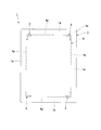
- FIG. 1 It is a figure which illustrates typically the manufacturing method of the film molding which is one Embodiment of this invention, and shows an example of the process of forming a U-shaped embossed part by planar view on the surface of a film using a metal mold
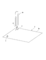
- FIG. It is a figure which illustrates typically the manufacturing method of the film molding which is one Embodiment of this invention, and is another example of the process of forming a U-shaped embossed part by plane view on the surface of a film using a metal mold
- FIG. It is a figure explaining the film packaging body which is other embodiment of this invention, and its manufacturing method, About the example which comprises a film packaging body by bend
- the top view which shows the state of the film package body after sealing at the time of conducting the experiment which piles up a pair of sheet-like films and packages a package object, changing the thickness of the package object by the conventional method It is.
- the top view which shows the state of the film package body after sealing at the time of conducting the experiment which piles up a pair of sheet-like films and packages a package object, changing the thickness of the package object by the conventional method It is.
- the film molded body 1 of the present embodiment has a concave or convex embossed portion 3 formed on the surface 2 a of the film 2. And these some embossed parts 3 are the surrounding area 4 enclosed by the virtual line 4a which connects between each of these several embossed parts 3 and these several embossed parts 3 in the surface of the film 2. It is arranged so as to form and is schematically configured.
- the film molded body 1 of this embodiment can be applied, for example, as a package of a product such as cosmetics or an exterior body of a lithium ion secondary battery.
- the film 2 for example, metal materials such as aluminum, stainless steel, and brass, and various sheet materials such as polymer films can be used.
- the film 2 may be comprised by the laminated film of a metal and resin, and the laminated film of aluminum and nylon resin, the laminated film of stainless steel and polypropylene resin, etc. are mentioned.
- a film having a thickness of about 10 to 800 ⁇ m can be used.
- the film 2 used in the present embodiment is preferably made of a plastic material capable of imparting a desired shape by plastic deformation. This is because a desired shape can be easily imparted to the surface 2a of the film 2 by a method such as stamping or pressing using a mold, which will be described later, and a film molded body having various shapes can be realized. Further, as a method for imparting a shape to the film 2 made of a plastic material, conventionally known methods such as pressure molding, heat pressure molding, vacuum molding, and heat vacuum molding can be used.
- the film 2 it is preferable to use a sealable laminate material.
- a sealable laminate material for the film, the sealing process when forming the film package by superimposing the film molded bodies 1 on each other is simplified, and productivity is improved. As can be seen, wrinkles can be remarkably suppressed in the film 2 (peripheral portion 1a).
- Examples of the sealable laminating material as described above include a laminating material that can be heat-sealed or pressure-sensitively sealed.
- Examples of the laminate material that can be heat-sealed include hot melt resins made of polyethylene resin, polypropylene resin, polyester resin, and the like.
- Examples of the laminate material capable of pressure-sensitive sealing include an adhesive material made of an acrylic resin, a silicone resin, or the like, an adhesive material such as an acrylic resin, a silicone resin, or an epoxy resin.
- a plurality of the embossed portions 3 are formed on the surface 2a of the film 2, and are formed in a concave shape or a convex shape when viewed from the surface 2a side.
- the embossed portion 3 in the illustrated example is formed in an L shape in a plan view, that is, in a triangular shape with no bottom portion in a plan view, and is roughly rectangular in four locations on the surface 2a of the film 2. It arrange
- the embossed part 3 is a part which becomes an edge part in the accommodating part of the packaged object when the film molded body 1 described later is configured by superimposing a pair of the film molded bodies 1.
- the concave accommodating portion is formed between the pair of film molded bodies 1 by being bent freely.
- this accommodating part is taken as the magnitude
- region 4 in the film molded object 1 is used as the peripheral part 1a at the time of comprising a pair of film molded objects 1 and comprising the below-mentioned film package.
- the protrusion (convex shape) dimension or depth (concave shape) dimension of the embossed portion 3 from the surface 2a of the film 2 is not particularly limited, but a pair of the film molded bodies 1 are overlapped to sandwich an object to be packaged.
- the thickness may be determined in consideration of the ease of bending when forming the portion (particularly the thickness of the package), for example, about 0.1 to 20 mm.
- the embossed portion 3 is formed in a triangular shape with a schematic shape having no bottom portion in a plan view, but is not limited to this, for example, as shown in FIG. 6.
- a roughly arc-shaped embossed portion 3 ⁇ / b> A may be formed.
- the surrounding region reference numeral 4 in FIG. 1 or reference numeral 4A in FIG. 6 can be formed with a stable shape, and a pair of film molded bodies 1 and 10 can be formed.
- the shape of the embossed portion can be a straight line, a polygonal line, a curved line, a quadrangle, a circle, a dot, or the like in plan view, and is not particularly limited.
- each of the embossed portions 3 formed at four places is connected by a virtual line 4a that is linear in a plan view, but is not limited thereto.
- each embossed part may be configured to be connected by a curved imaginary line in a plan view.
- the usage form of the film molded body It is possible to design appropriately according to the above.
- the imaginary line is drawn so that the maximum enclosed region is secured by connecting arbitrary points of the plurality of embossed portions. A straight line is preferable.
- the area of the surrounding region is preferably 100% or more of the area of the packaged object, and more preferably exceeds 100%. More specifically, if the area of the surrounding region is in the range of 101 to 105% of the area of the packaged object, the film molded object 1 and 10 are overlapped to wrap the packaged object, and the film described later When configuring a package, it is possible to more effectively suppress wrinkles from being generated on the film.
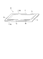
- two embossed portions 3B formed in a substantially trapezoidal shape in a plan view on the surface 200a of the film 200 are opposed to each other as in the film molded body 100 shown in FIGS. 8A and 8B. May be arranged.
- the embossed portion 3B formed in a trapezoidal shape in plan view adopts a configuration in which the region surrounded by the trapezoidal shape on the surface 200a of the film 200 is formed in a concave shape or a convex shape. Also good.
- the embossed portion 3B is formed as a planar concave portion so as to be recessed downward (downward in the longitudinal direction in FIG. 8B) from the surface 200a side of the film 200 with the tip 3a as the lowermost portion. .
- the embossed part 3B provided in the film molded body 100 is the same as the embossed part 3 provided in the film molded body 1 shown in FIG. Arranged so as to form a surrounding region 4C surrounded by a virtual line 4b that linearly connects the portions 3B.
- an embossed part is made into the shape from which the dimension of a thickness direction changes in a step shape in many steps in the thickness direction from the surface of a film. It may be formed.
- the manufacturing method of the film molded body 1 of this embodiment is a method of forming a concave or convex embossed portion 3 on the surface 2a of the film 2 as shown in FIG. That is, in the manufacturing method of the present embodiment, a plurality of embossed portions 3 are formed on the surface 2a of the film 2 by applying a shape to at least a part of the surface 2a of the film 2 with a mold and plastically deforming the film 2.
- the embossed portion 3 is formed so that a plurality of the embossed portions 3 are spaced apart from each other, and the surrounding region 4 surrounded by the plurality of embossed portions 3 and the virtual line 4a connecting each of the embossed portions 3 is formed. It is a method of forming so as to ensure.
- the mold includes a male punch 20 as shown in FIGS. 2 and 3 and a female unillustrated die, and the shape of the distal end portion 21 in plan view is schematic.
- a method of forming a plurality of substantially triangular embossed portions 3 in a plan view on the surface 2a of the film 2 by stamping the surface 2a of the film 2 using the punch 20 having a triangular shape will be described as an example. .
- the film 2 is placed on a die not shown.
- the die constitutes a mold together with the punch 20 and is disposed on the surface opposite to the surface 2 a of the film 2, and the shape of the tip portion 21 of the punch 20 enters. It is set as the shape in which such a recessed part was formed.
- the punch 20 is moved in the D direction, and the formation planned position of the embossed portion 3 on the surface 2a of the film 2 is imprinted.
- the embossed part 3 is formed at one place on the surface 2a of the film 2, and then the punch 20 is moved to another formation planned position of the embossed part 3 on the film 2, and is stamped in the same manner as described above.
- the embossed part 3 is formed.
- a plurality of embossed portions 3 are sequentially formed by repeating such a procedure.
- FIG. 3 shows a state in which the embossed portions 3 are formed at two locations on the surface 2a of the film 2, but the manufacturing method of the present embodiment is finally as in the example shown in FIG.
- the embossed portions 3 are formed at a total of four locations so as to form the surrounding region 4 surrounded by the virtual line 4a.
- the formation position and the number of formation of the embossed part 3 are not limited, and should be appropriately determined in consideration of the shape and dimensions of the package object when configuring the film package described later. Can do.
- the embossed portions 3 are formed at a total of four locations.
- the embossed portion 3 is arranged at four locations to form the surrounding region 4 that is substantially rectangular in a plan view.
- the present invention is not limited to this.
- a plurality of embossed portions may be arranged so as to form a surrounding region, or a plurality of embossed portions may be arranged so as to form a substantially circular surrounding region.
- the film molded body 1 of the present embodiment has a configuration in which a plurality of embossed portions 3 are formed on the surface 2a of the film 2 and the surrounding region 4 is secured by connecting these embossed portions 3 with virtual lines 4a. Without using a large-sized manufacturing apparatus, it can be manufactured using a mold made of the small punch 20 as described above. Thereby, the film molded body 1 can be manufactured with high productivity and at low cost. Moreover, when the film molded body 1 of this embodiment is overlap
- a punch 20 is used in which the shape of the tip portion 21 is substantially L-shaped in plan view and is roughly formed in a triangular shape having no bottom portion.
- the method for forming the embossed portion 3 having a substantially L shape (generally triangular shape) in a plan view as shown in FIGS. 1 and 3 is described, but is not limited thereto.
- a punch 30 having a shape in which the tip 31 is completely embedded as shown in FIG. 4 may be used, and the surface 2a of the film 2 may be stamped.
- the embossed portion formed on the surface 2a of the film 2 can be shaped by adjusting the stamping angle of the punch 30 with respect to the film 2 or by using a punch having an angle provided at the tip.
- the shape can be changed smoothly in the thickness direction from the surface 2a.
- the punching angle of the punch 40 with respect to the film is adjusted, or by using a punch with an angle provided in advance at the tip, for example, on the surface 25a of the film 25 as shown in FIG.
- the embossed portion 3A in which only the portion corresponding to the vicinity of the arc portion of the tip portion 41 of the punch 40 is deformed may be formed.
- the shape of the embossed portion formed on the surface 2a of the film 2 can be smoothly changed from the surface 2a by adjusting the punching angle of the punch 40 with respect to the film 2. It can be.
- the mold is composed of the punch 20 (30, 40) and a die (not shown), and the shape of the tip portion 21 (31, 41) of the punch 20 (30, 40).
- the stamping position to the surface 2a of the film 2 by the punch 20 is set.
- the stamping position to the surface 2a of the film 2 by the punch 20 is set.
- the embossed portion 3B when the embossed portion 3B is formed in a U shape in a plan view on the surface 200a of the film 200, like the film molded body 100 shown in FIGS. 8A and 8B, the embossed portion 3B
- the following method can be employed when forming the film in a concave or convex shape.
- the surface 200a of the film 200 is surrounded by the U shape. An example in which the region is formed as a concave surface will be described.
- FIG. 9 is a schematic view showing an example of the process of forming the U-shaped embossed portion 3B on the surface 200a of the film 200 using the mold 50 from above the film 200.
- a mold 50 shown in FIG. 9 includes two protrusions 51 (51A, 51B: indicated by hidden chain lines in FIG. 9) on the outer surface of the base plate 50A in contact with the surface 200a of the film 200. Is formed in a U shape in plan view. The protrusions 51A and 51B are arranged so that the U-shaped directions are opposite to each other.
- the base plate 50A of the mold 50 is provided with a total of four holes 52 into which guide rods (not shown) for inserting the base plate 50A by sliding movement are inserted.
- the base plate 50 ⁇ / b> A of the mold 50 is provided with pin holes 53 that can be used for alignment of the film 200.
- the mold 50 is provided with a die member in which a concave portion into which the shape of the protruding portion 51 enters is formed on the side facing the base plate 50A through the film 200. .
- die 50 when forming a concave embossed part on the surface 200a of the film 200 using said metal mold
- die 50 first, the elongate film 200 pulled out from the roll part of the illustration not shown wound by roll shape is carried out. Then, it is introduced into the mold 50 so as to be inserted between the base plate 50A and a die member (not shown). Next, the base plate 50A guided by a guide rod (not shown) is slid along the guide rod, and the projection 51 is brought into contact with the surface 200a, thereby hitting the planned formation position of the embossed portion on the surface 200a. Engrave. At this time, the embossed portion 3B (see FIGS. 8A and 8B) is formed at two locations by stamping two locations on the surface 200a of the film 200 by the projecting portions 51A and 51B.
- the base plate 50 ⁇ / b> A is slid to move away from the film 200.
- the film 200 is cut at an intermediate position between the two embossed portions (corresponding to the positions of the protruding portions 51A and 51B in FIG. 9), that is, the position of the C line shown in FIG. .
- Such a cutting process of the film 200 can be performed by, for example, a movable cutter (not shown) provided in the mold 50.
- the cut film 200 is transported in the direction of arrow Y shown in FIG. It arrange
- the embosses 3B and 3B are formed by the protrusions 51A and 51B of the mold 50. After that, by cutting at the position of the C line between the embosses 3B and 3B, it is possible to suppress the occurrence of sink marks on the cut surface of the film 200.
- the method of manufacturing the film molded body 100 as shown in FIGS. 8A and 8B is not limited to the above method, and for example, a method using a mold 60 as shown in FIG. 10 may be adopted.
- 10 includes a protrusion 61 (indicated by a hidden chain line in FIG. 10) in contact with the surface 200a of the film 200 on the outer surface of the base plate 60A.
- the protrusion 61 is U-shaped in plan view. Is formed.
- the mold 60 has a recess in which the shape of the projection 61 enters the side facing the base plate 60A through the film 200, as in the case of the mold 50 described above.
- a formed die member is provided.
- the concave embossed portion is formed on the surface 200a of the film 200 using the mold 60
- the long film 200 is first formed on the base plate 50A and a die (not shown) as described above. Insert between the members.
- the embossed portion 3B is formed by stamping the formation position of the embossed portion on the surface 200a by bringing the protruding portion 61 into contact with the surface 200a of the film 200. It is formed.
- the base plate 60A is rotated by a rotation mechanism (not shown) to move the base plate 60A to the distillation side of the film 200 (indicated by an arrow R shown in FIG. 10 and a two-dot chain phantom line). (See Mold 60).
- a rotation mechanism not shown
- the base plate 60 ⁇ / b> A is rotationally moved, the U-shaped direction of the protrusion 61 is reversed in the longitudinal direction of the film 200.
- the base plate 60A that has been rotated is moved to the film 200 side, and the protrusion 61 is brought into contact with the surface 200a of the film 200, thereby forming the embossed portion by stamping the formation position of the embossed portion.
- a film molded body 100 as shown in FIGS. 8A and 8B can be manufactured.
- the method of stamping the surface of the film with a mold (punch) is described as an example.
- the method is not limited to this.
- Each method can be adopted without any limitation.
- FIG. 7 is a perspective view showing the film package 11 in a state in which the package object 5 is packaged by overlapping the pair of film molded bodies 1.
- the film package 11 of the present embodiment is a film package 11 in which the above-described film molded body 1 of the present embodiment is overlapped in a pair. And as for the film packaging body 11, while the to-be packaged object 5 is arrange
- the package 5 to be housed and packaged in the film package 11 of the present embodiment includes, for example, cosmetics and lithium secondary battery cells, and other various packages. Applicable without any restrictions.
- the lithium secondary battery cell to be used is not particularly limited.
- a lithium secondary battery cell applied to the package 5 a positive electrode sheet provided with a positive electrode active material layer on a positive electrode current collector, and a negative electrode current collector
- a negative electrode sheet provided with a negative electrode active material layer can be used which is composed of a laminate obtained by laminating via a separator.
- said laminated body as the to-be-packaged object 5, the nonaqueous electrolyte not shown is accommodated in the inside of the film package 11 with this laminated body.
- peripheral portions 1a of the pair of film molded bodies 1 for example, a method such as adhesion or heat sealing can be used. It is preferable from the viewpoints of hermeticity and productivity that the peripheral edges 1a are heat-sealed using the film 2.
- the package 5 is disposed in the surrounding region 4 formed in one film molded body 1A of the pair of film molded bodies 1 (1A, 1B). To do. More specifically, for example, the package shown in FIG. 7 so as to fit in the surrounding region 4 secured on the film molded body 1 (one film molded body 1A shown in FIG. 7) as shown in FIG. Object 5 is arranged.
- the other film molded body 1B having the same configuration as the film molded body 1 in FIG. 1 is packaged in an unillustrated surrounding region formed in the other film molded body 1B. While covering the object 5, it is superposed on one film molded body 1A. And the peripheral part 1a of a pair of film molded object 1 (1A, 1B) is sealed under vacuum pressure reduction in the state which sandwiched the to-be-packaged object 5 with a pair of film molded object 1 (1A, 1B).
- a method for sealing the peripheral edge portion 1a a method can be employed in which the peripheral edge portion 1a is fused by heating and pressing using a vacuum laminator, a roller, or a vacuum packaging machine.
- interposed the to-be-packaged object 5 is a pair of film molded object 1 (1A, 1B).
- the concave accommodating portion 4B is formed as viewed from the joint surface side.
- the package 5 is packaged using a pair of film molded bodies 1 that are not provided with a shape at the position of the imaginary line 4a that connects the embossed portions 3 that are concave or convex. .
- the peripheral edges of the pair of film molded bodies 1 (1A, 1B) while the positions of the virtual lines 4a forming the plurality of embossed portions 3 and the surrounding region 4 are freely bent according to the shape and size of the packaged object.
- the parts 1a are sealed. Thereby, for example, even when the battery cell formed into a thick laminate is packaged and each peripheral edge 1a is sealed, the peripheral edge 1a starts from the vicinity of the edge of the accommodation space of the article 5 to be packaged. It is possible to suppress the occurrence of soot.
- a nonaqueous electrolyte is injected from the position of one unsealed peripheral portion 1a. Then, it can be set as the method of sealing the unsealed peripheral part 1a under vacuum pressure reduction.
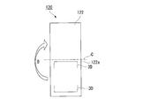
- a film packaging body by forming a long film like the film molded body 110 shown in FIGS. 11A and 11B, and bending and overlapping this from the center line C. .
- a film molded body 110 shown in FIGS. 11A and 11B has a U-shaped embossed portion 3 ⁇ / b> C formed at one location on one end side in the longitudinal direction of the film 112. Then, the film molded body 110 is folded in the direction of arrow B shown in FIG. 11A with the surface 112a of the film 112 facing inward, and an unillustrated packaged article is accommodated in the interior (accommodating portion), whereby film packaging A body can be constructed (see also FIG. 11B). Under the present circumstances, the peripheral part in the surface 112a of the film 112 can be sealed by the method similar to the film molded object 1 and the film package 11 which were mentioned above.
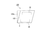
- the film 122 is formed in a U shape in plan view on one end side from the center line C in the longitudinal direction.
- a configuration in which the two embossed portions 3D are disposed to face each other may be employed.
- two embossed portions formed in a U shape in plan view on each of both end sides through the center line C in the longitudinal direction of the film 132.
- a configuration may be adopted in which the portions 3E are arranged to face each other and a total of four embossed portions 3E are provided.
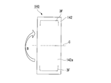
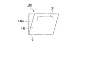
- one embossed portion formed in a U shape in plan view on each of both end sides through the center line in the longitudinal direction of the film 142.
- a configuration in which 3Es are arranged to face each other via the center line C may be adopted.
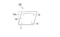
- 3G may be arranged so as to face each other, and two embossed portions 3G arranged in the vicinity of the center line C may be employed.
- the long films 112, 122, 132, 142, and 152 are centered on the center line C. It is the structure which is bent from the side to make a film package. Thereby, since the number of parts is reduced, productivity is improved and manufacturing cost can be reduced.
- FIGS. 16A, 16B, and 16C show the sealing when the thickness of the packaged object is changed in an experiment in which the packaged object is packaged by overlapping a pair of film molded bodies according to the present embodiment. It is a top view which shows the state of the film packaging body after. 17A, FIG. 17B and FIG.
- 17C are the conventional methods, while changing the thickness of the object to be packaged in the same manner as described above, when an experiment for packaging the object to be packaged by overlapping a pair of sheet-like films was performed. It is a top view which shows the state of the film package body after sealing.
- the film molded body is deformed in either case (FIG. 16A), when a packaged object having a thickness of 2 mm is packaged (FIG. 16B), or when a packaged object having a thickness of 3 mm is packaged (FIG. 16C).
- FIGS. 16A to 16C There was no occurrence of wrinkles or the like starting from the housing portion formed in (1).
- FIGS. 17A to 17C in the case of packaging a package by overlapping the film in the form of a sheet without any processing, the package having a thickness of 1 mm is packaged.
- FIG. 17A In the case where an object to be packaged having a thickness of 2 mm was packaged (FIG. 17B), wrinkles were not particularly generated on the film.
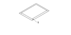
- FIG. 17C when a relatively thick article having a thickness of 3 mm is packaged (FIG. 17C), the bag S extends so as to extend from one of the corners of the accommodating portion formed by the deformation of the sheet-like film. Has been confirmed to occur.
- the film packaging body 11 in which the film molded body 1 provided with the embossed portion 3 according to the present embodiment is overlapped in a pair and the packaged object 5 is packaged causes generation of wrinkles at the time of sealing. It became clear that it was possible to suppress this.
Landscapes
- Mechanical Engineering (AREA)
- Engineering & Computer Science (AREA)
- Chemical & Material Sciences (AREA)
- General Chemical & Material Sciences (AREA)
- Chemical Kinetics & Catalysis (AREA)
- Electrochemistry (AREA)
- Composite Materials (AREA)
- Packages (AREA)
- Sealing Battery Cases Or Jackets (AREA)
- Containers And Plastic Fillers For Packaging (AREA)
- Wrappers (AREA)
- Blow-Moulding Or Thermoforming Of Plastics Or The Like (AREA)
- Shaping Of Tube Ends By Bending Or Straightening (AREA)
Abstract
Priority Applications (6)
| Application Number | Priority Date | Filing Date | Title |
|---|---|---|---|
| JP2016538398A JP6543256B2 (ja) | 2014-07-29 | 2015-07-29 | フィルム成形体及びそれを用いたフィルム包装体、フィルム成形体の製造方法及びフィルム包装体の製造方法 |
| CN201580039609.2A CN106573409B (zh) | 2014-07-29 | 2015-07-29 | 膜成形体及使用其的膜包装体、膜成形体的制造方法及膜包装体的制造方法 |
| KR1020177001067A KR20170038788A (ko) | 2014-07-29 | 2015-07-29 | 필름 성형체 및 그것을 사용한 필름 포장체, 필름 성형체의 제조 방법 및 필름 포장체의 제조 방법 |
| EP15828013.1A EP3175971A4 (fr) | 2014-07-29 | 2015-07-29 | Article moulé formant film, corps emballé dans ledit film, procédé de fabrication d'article moulé formant film et procédé de fabrication de corps emballé dans ledit film |
| US15/327,372 US20170166373A1 (en) | 2014-07-29 | 2015-07-29 | Film molded article, film packaged body using the same, manufacturing method for film molded article and manufacturing method for film packaged body |
| US16/925,213 US20200339331A1 (en) | 2014-07-29 | 2020-07-09 | Film packaged body and manufacturing method for film packaged body |
Applications Claiming Priority (4)
| Application Number | Priority Date | Filing Date | Title |
|---|---|---|---|
| JP2014153763 | 2014-07-29 | ||
| JP2014-153763 | 2014-07-29 | ||
| JP2015-059854 | 2015-03-23 | ||
| JP2015059854 | 2015-03-23 |
Related Child Applications (2)
| Application Number | Title | Priority Date | Filing Date |
|---|---|---|---|
| US15/327,372 A-371-Of-International US20170166373A1 (en) | 2014-07-29 | 2015-07-29 | Film molded article, film packaged body using the same, manufacturing method for film molded article and manufacturing method for film packaged body |
| US16/925,213 Continuation-In-Part US20200339331A1 (en) | 2014-07-29 | 2020-07-09 | Film packaged body and manufacturing method for film packaged body |
Publications (1)
| Publication Number | Publication Date |
|---|---|
| WO2016017691A1 true WO2016017691A1 (fr) | 2016-02-04 |
Family
ID=55217589
Family Applications (1)
| Application Number | Title | Priority Date | Filing Date |
|---|---|---|---|
| PCT/JP2015/071501 Ceased WO2016017691A1 (fr) | 2014-07-29 | 2015-07-29 | Article moulé formant film, corps emballé dans ledit film, procédé de fabrication d'article moulé formant film et procédé de fabrication de corps emballé dans ledit film |
Country Status (7)
| Country | Link |
|---|---|
| US (1) | US20170166373A1 (fr) |
| EP (1) | EP3175971A4 (fr) |
| JP (2) | JP6543256B2 (fr) |
| KR (1) | KR20170038788A (fr) |
| CN (2) | CN106573409B (fr) |
| TW (1) | TWI665077B (fr) |
| WO (1) | WO2016017691A1 (fr) |
Cited By (3)
| Publication number | Priority date | Publication date | Assignee | Title |
|---|---|---|---|---|
| JP2018129203A (ja) * | 2017-02-09 | 2018-08-16 | 日産自動車株式会社 | フィルム外装電池の製造方法およびフィルム外装電池 |
| JP2018137112A (ja) * | 2017-02-21 | 2018-08-30 | 積水化学工業株式会社 | 電池 |
| JP2019537225A (ja) * | 2017-07-20 | 2019-12-19 | エルジー・ケム・リミテッド | 二次電池用パウチ外装材、これを用いたパウチ型二次電池及びこの製造方法 |
Families Citing this family (5)
| Publication number | Priority date | Publication date | Assignee | Title |
|---|---|---|---|---|
| CN109301337A (zh) * | 2018-09-20 | 2019-02-01 | 惠州赛尔雷新能源科技有限公司 | 一种上下模加热封装的电池装配设备及其装配方法 |
| KR102835332B1 (ko) | 2019-12-09 | 2025-07-17 | 주식회사 엘지에너지솔루션 | 보호필름을 이용한 파우치형 전지셀의 제조방법 및 이를 이용하여 제조된 파우치형 전지셀 |
| JP7310584B2 (ja) * | 2019-12-13 | 2023-07-19 | トヨタ自動車株式会社 | 外装体、ラミネート電池および外装体の製造方法 |
| KR102269614B1 (ko) * | 2020-11-10 | 2021-06-28 | 안혁 | 이차전지 파우치의 형상주름을 제거하는 포밍금형 구조체 |
| KR102739769B1 (ko) * | 2020-11-26 | 2024-12-05 | 주식회사 엘지에너지솔루션 | 전지셀 제조 방법 및 파우치 성형 장치 |
Citations (5)
| Publication number | Priority date | Publication date | Assignee | Title |
|---|---|---|---|---|
| JP2000133216A (ja) * | 1998-10-23 | 2000-05-12 | Sony Corp | 非水電解質電池及びその製造方法 |
| JP2003251714A (ja) * | 2002-03-01 | 2003-09-09 | Shibaura Mechatronics Corp | シート加工方法及び装置 |
| JP2004039271A (ja) * | 2002-06-28 | 2004-02-05 | Nissan Motor Co Ltd | 電池外装ケースの密封構造 |
| JP2009170379A (ja) * | 2008-01-21 | 2009-07-30 | Nec Tokin Corp | 積層型密閉電池 |
| JP2010173281A (ja) * | 2009-02-02 | 2010-08-12 | Matsumoto Seisakusho:Kk | 折り曲げ線入りプラスチックシートおよびプラスチックシートへの折り曲げ線加工方法 |
Family Cites Families (16)
| Publication number | Priority date | Publication date | Assignee | Title |
|---|---|---|---|---|
| JPS5859048A (ja) * | 1981-09-26 | 1983-04-07 | Sekisui Plastics Co Ltd | 中空成形品およびその製造方法 |
| DE3921434A1 (de) * | 1989-06-30 | 1991-01-17 | Lohmann Therapie Syst Lts | Vorrichtung und verpackung von selbstklebenden substratabschnitten und ihre verwendung |
| DE59606545D1 (de) * | 1995-12-12 | 2001-04-12 | Alusuisse Tech & Man Ag | Verfahren zum Herstellen von Blisterverpackungen |
| JPH10109358A (ja) * | 1996-10-04 | 1998-04-28 | Terufumi Machida | 容器成形装置及び方法 |
| JP2933130B2 (ja) * | 1996-10-18 | 1999-08-09 | 信越ポリマー株式会社 | キャリアテープおよびキャリアテープ成形用金型装置 |
| JP4171855B2 (ja) * | 1999-08-06 | 2008-10-29 | 株式会社ジーエス・ユアサコーポレーション | 電池 |
| MY126840A (en) * | 2000-06-23 | 2006-10-31 | Sumitomo Bakelite Co | Electronic parts carrier tape |
| JP3875007B2 (ja) * | 2000-09-01 | 2007-01-31 | ユニ・チャーム株式会社 | 連続フィラメントを有する表面層を用いた吸収性物品およびその製造方法 |
| US7032773B2 (en) * | 2001-05-25 | 2006-04-25 | Fort James Corporation | Food container with interchangeable lid—base seal provided with undercut sealing profile and asymmetric interlockable stacking ridges |
| JP4281302B2 (ja) | 2002-07-16 | 2009-06-17 | 日本電気株式会社 | フィルム外装体の製造方法 |
| KR100571269B1 (ko) * | 2004-09-22 | 2006-04-13 | 삼성에스디아이 주식회사 | 이차전지용 파우치 및 파우치형 이차전지 |
| JP5054419B2 (ja) * | 2006-07-06 | 2012-10-24 | エナックス株式会社 | シート状二次電池 |
| WO2011089965A1 (fr) * | 2010-01-19 | 2011-07-28 | エナックス株式会社 | Batterie secondaire de type feuille et son procédé de fabrication |
| US9474420B2 (en) * | 2010-08-30 | 2016-10-25 | Dixie Consumer Products Llc | Sealable snack container |
| KR101192619B1 (ko) * | 2012-03-23 | 2012-10-18 | 주식회사 엘지화학 | 전지케이스 |
| JP6160009B2 (ja) | 2012-08-17 | 2017-07-12 | 株式会社フジシール | スキンパック包装体、及びスキンパック包装体の製造方法 |
-
2015
- 2015-07-29 CN CN201580039609.2A patent/CN106573409B/zh active Active
- 2015-07-29 WO PCT/JP2015/071501 patent/WO2016017691A1/fr not_active Ceased
- 2015-07-29 US US15/327,372 patent/US20170166373A1/en not_active Abandoned
- 2015-07-29 TW TW104124499A patent/TWI665077B/zh active
- 2015-07-29 CN CN202010794604.3A patent/CN111907924A/zh active Pending
- 2015-07-29 EP EP15828013.1A patent/EP3175971A4/fr not_active Withdrawn
- 2015-07-29 KR KR1020177001067A patent/KR20170038788A/ko not_active Ceased
- 2015-07-29 JP JP2016538398A patent/JP6543256B2/ja active Active
-
2019
- 2019-04-22 JP JP2019081324A patent/JP6734432B2/ja active Active
Patent Citations (5)
| Publication number | Priority date | Publication date | Assignee | Title |
|---|---|---|---|---|
| JP2000133216A (ja) * | 1998-10-23 | 2000-05-12 | Sony Corp | 非水電解質電池及びその製造方法 |
| JP2003251714A (ja) * | 2002-03-01 | 2003-09-09 | Shibaura Mechatronics Corp | シート加工方法及び装置 |
| JP2004039271A (ja) * | 2002-06-28 | 2004-02-05 | Nissan Motor Co Ltd | 電池外装ケースの密封構造 |
| JP2009170379A (ja) * | 2008-01-21 | 2009-07-30 | Nec Tokin Corp | 積層型密閉電池 |
| JP2010173281A (ja) * | 2009-02-02 | 2010-08-12 | Matsumoto Seisakusho:Kk | 折り曲げ線入りプラスチックシートおよびプラスチックシートへの折り曲げ線加工方法 |
Non-Patent Citations (1)
| Title |
|---|
| See also references of EP3175971A4 * |
Cited By (3)
| Publication number | Priority date | Publication date | Assignee | Title |
|---|---|---|---|---|
| JP2018129203A (ja) * | 2017-02-09 | 2018-08-16 | 日産自動車株式会社 | フィルム外装電池の製造方法およびフィルム外装電池 |
| JP2018137112A (ja) * | 2017-02-21 | 2018-08-30 | 積水化学工業株式会社 | 電池 |
| JP2019537225A (ja) * | 2017-07-20 | 2019-12-19 | エルジー・ケム・リミテッド | 二次電池用パウチ外装材、これを用いたパウチ型二次電池及びこの製造方法 |
Also Published As
| Publication number | Publication date |
|---|---|
| JP6543256B2 (ja) | 2019-07-10 |
| EP3175971A4 (fr) | 2018-04-04 |
| TWI665077B (zh) | 2019-07-11 |
| KR20170038788A (ko) | 2017-04-07 |
| JP6734432B2 (ja) | 2020-08-05 |
| US20170166373A1 (en) | 2017-06-15 |
| CN111907924A (zh) | 2020-11-10 |
| CN106573409A (zh) | 2017-04-19 |
| TW201615518A (zh) | 2016-05-01 |
| JPWO2016017691A1 (ja) | 2017-05-25 |
| CN106573409B (zh) | 2020-09-04 |
| EP3175971A1 (fr) | 2017-06-07 |
| JP2019123556A (ja) | 2019-07-25 |
Similar Documents
| Publication | Publication Date | Title |
|---|---|---|
| JP6734432B2 (ja) | フィルム成形体及びそれを用いたフィルム包装体、フィルム成形体の製造方法及びフィルム包装体の製造方法 | |
| KR102261672B1 (ko) | 말림 방지 가이드 라인이 형성된 전지케이스 및 이의 제조장치 | |
| US11638948B2 (en) | Electrochemical cell having wave corner sealed joints, and device and method for forming same | |
| JP6610606B2 (ja) | ラミネート電池の製造方法 | |
| JP7807158B2 (ja) | 成形装置および成形方法、それにより製造されるパウチ型電池ケース、並びにそれを含む二次電池 | |
| JP2014046655A (ja) | 積層フィルムの立体成形方法およびその装置 | |
| JP2013154389A (ja) | 絞り加工用金型 | |
| JP6202753B2 (ja) | 電池容器、フィルム包装電池及び電池容器の製造方法 | |
| KR20170057251A (ko) | 이차 전지의 제조 방법 | |
| CN113725498A (zh) | 一种软包扣式电芯的制作方法及软包扣式电池 | |
| JP2023550896A (ja) | エンボスパターンが形成されたシーリング部を含む電池セル及びこれを製造するためのシーリングブロック | |
| JP5480737B2 (ja) | 電池用ケースの製造方法及び電池用ケース | |
| JP2026001229A (ja) | 電池 | |
| US20200339331A1 (en) | Film packaged body and manufacturing method for film packaged body | |
| JP2010232067A (ja) | ラミネート外装電池 | |
| KR20210157885A (ko) | 밀폐형 전지 | |
| JP5996198B2 (ja) | 絞り加工用金型 | |
| JP7135905B2 (ja) | 電極外装体の製造方法 | |
| JP2018129203A (ja) | フィルム外装電池の製造方法およびフィルム外装電池 | |
| JP7589684B2 (ja) | フィルムの立体加工方法、圧縮金型、フィルム、およびフィルム成形体 | |
| JP2001205700A (ja) | ワーク押圧装置 | |
| JP2024047137A (ja) | 蓄電モジュールの製造方法および貼付ユニット | |
| JP2024047140A (ja) | 蓄電モジュールの製造方法および貼付ユニット | |
| JP2025525109A (ja) | パウチ型電池ケース及びそのフォーミング装置 |
Legal Events
| Date | Code | Title | Description |
|---|---|---|---|
| 121 | Ep: the epo has been informed by wipo that ep was designated in this application |
Ref document number: 15828013 Country of ref document: EP Kind code of ref document: A1 |
|
| ENP | Entry into the national phase |
Ref document number: 2016538398 Country of ref document: JP Kind code of ref document: A |
|
| ENP | Entry into the national phase |
Ref document number: 20177001067 Country of ref document: KR Kind code of ref document: A |
|
| REEP | Request for entry into the european phase |
Ref document number: 2015828013 Country of ref document: EP |
|
| WWE | Wipo information: entry into national phase |
Ref document number: 15327372 Country of ref document: US Ref document number: 2015828013 Country of ref document: EP |
|
| NENP | Non-entry into the national phase |
Ref country code: DE |