WO2016017706A1 - コリメーション評価装置およびコリメーション評価方法 - Google Patents
コリメーション評価装置およびコリメーション評価方法 Download PDFInfo
- Publication number
- WO2016017706A1 WO2016017706A1 PCT/JP2015/071528 JP2015071528W WO2016017706A1 WO 2016017706 A1 WO2016017706 A1 WO 2016017706A1 JP 2015071528 W JP2015071528 W JP 2015071528W WO 2016017706 A1 WO2016017706 A1 WO 2016017706A1
- Authority
- WO
- WIPO (PCT)
- Prior art keywords
- reflecting
- light
- reflecting surface
- reflecting member
- collimation
- Prior art date
- Legal status (The legal status is an assumption and is not a legal conclusion. Google has not performed a legal analysis and makes no representation as to the accuracy of the status listed.)
- Ceased
Links
Images


Classifications
-
- G—PHYSICS
- G01—MEASURING; TESTING
- G01M—TESTING STATIC OR DYNAMIC BALANCE OF MACHINES OR STRUCTURES; TESTING OF STRUCTURES OR APPARATUS, NOT OTHERWISE PROVIDED FOR
- G01M11/00—Testing of optical apparatus; Testing structures by optical methods not otherwise provided for
-
- G—PHYSICS
- G01—MEASURING; TESTING
- G01J—MEASUREMENT OF INTENSITY, VELOCITY, SPECTRAL CONTENT, POLARISATION, PHASE OR PULSE CHARACTERISTICS OF INFRARED, VISIBLE OR ULTRAVIOLET LIGHT; COLORIMETRY; RADIATION PYROMETRY
- G01J9/00—Measuring optical phase difference; Determining degree of coherence; Measuring optical wavelength
- G01J9/02—Measuring optical phase difference; Determining degree of coherence; Measuring optical wavelength by interferometric methods
- G01J9/0215—Measuring optical phase difference; Determining degree of coherence; Measuring optical wavelength by interferometric methods by shearing interferometric methods
Definitions
- the present invention relates to an apparatus and a method for evaluating collimation of light.
- the frequency of diverging light emitted from a point light source (including one that can be regarded as a point light source) to parallel light (collimating) is high.
- the point light source include a laser diode and an optical fiber emitting end.
- divergent light emitted from the point light source can be converted into parallel light by the collimating optical system.
- Patent Documents 1 and 2 describe techniques for evaluating the parallelism (degree of collimation) of parallel light generated in this way.
- Patent Document 1 can easily evaluate the collimation of light using a shear plate having a first reflecting surface and a second reflecting surface that are non-parallel to each other. That is, the collimation evaluation apparatus using the shear plate causes the light reflected by the first reflecting surface of the shear plate to interfere with the light transmitted through the first reflecting surface of the shear plate and reflected by the second reflecting surface on the screen. The collimation of light can be evaluated based on the direction of interference fringes on the screen.
- the share plate is sometimes called a sharing plate.
- JP 2001-336914 A Japanese Patent No. 4114847
- the thickness of the shear plate in order to detect a change in the direction of interference fringes on the screen with high sensitivity. It is desirable to reduce the angle between the surfaces (wedge angle). Among them, since the wedge angle affects the interference fringe interval, it is determined to some extent by the interference fringe interval suitable for collimation evaluation. Therefore, in order to improve sensitivity, the thickness of the shear plate is increased.
- ⁇ A difference in optical path length occurs between the two light components from the two reflecting surfaces of the shear plate until reaching the screen.
- the optical path length difference increases.
- the interference fringes can be observed on the screen when the optical path length difference is shorter than the coherence distance (coherence length) of the light to be collimated.
- the coherence distance of the CW laser beam output from the HeNe laser light source is on the order of 100 mm.
- the coherence distance of the pulse laser beam with a pulse width of 40 ns output from the solid-state laser light source is several mm.
- the coherence distance of the pulse laser beam having a pulse width of 40 ns output from the optical fiber laser light source is 1 mm or less.
- a short pulse laser beam output from a solid-state laser light source or an optical fiber laser light source has a short coherence distance due to a multi-longitudinal mode or spectral broadening.
- the present invention has been made to solve the above-described problems, and provides an apparatus and method that can evaluate collimation of light with high sensitivity even when the coherence distance of light to be collimated is short.
- the purpose is to provide.
- a collimation evaluation apparatus includes (1) a first reflection surface that reflects a part of incident light, and a second reflection surface that reflects light transmitted through the first reflection surface of the incident light.
- the collimation of incident light is evaluated based on the direction of interference fringes formed by light reflected by the first reflecting surface of the two reflecting members.
- the collimation evaluation method includes (1) a first reflection surface that reflects a part of incident light, and a second reflection surface that reflects light that has passed through the first reflection surface of the incident light.
- a first reflecting member (2) a first reflecting surface that reflects a portion of the light emitted from the first reflecting member; and a second reflecting surface that reflects light transmitted through the first reflecting surface of the light.
- the interference fringes formed by the light reflected by the first reflecting surface of the two reflecting members are observed, and (b) collimation of the incident light is evaluated based on the observed orientation of the interference fringes.
- the collimation evaluation target light first enters the first reflecting member, and a part of the light is reflected by the first reflecting surface of the first reflecting member, and this first reflection is performed.
- the light transmitted through the surface is reflected by the second reflecting surface of the first reflecting member.
- the light reflected by the first reflecting member then enters the second reflecting member, a part of the light is reflected by the first reflecting surface of the second reflecting member, and the light transmitted through the first reflecting surface is the first. Reflected by the second reflecting surface of the two reflecting members.
- the light L 12 reflected by the first reflecting surface of the first reflecting member and the second reflecting surface of the second reflecting member, and the second reflecting surface and the second reflecting member of the first reflecting member Since the optical path length difference with the light L 21 reflected by the first reflecting surface can be made smaller than the coherence distance, interference fringes due to these two light components L 12 and L 21 can be observed.
- the collimation of incident light can be evaluated based on the observed direction of interference fringes.
- the collimation of the light can be evaluated with high sensitivity.
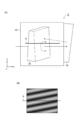
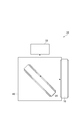
- FIG. 1 is a diagram illustrating a configuration of a collimation evaluation apparatus 100 of a comparative example.
- FIG. 2 is a diagram for explaining interference fringes formed on the screen 30 of the collimation evaluation apparatus 100 of the comparative examples (a) to (c).
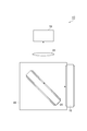
- FIG. 3 is a diagram illustrating a configuration of the collimation evaluation apparatus 1 according to the first embodiment.
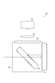
- FIG. 4 is a diagram illustrating a configuration of the collimation evaluation apparatus 2 according to the second embodiment.
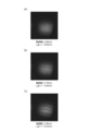
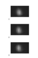
- FIG. 5 is a photograph of interference fringes observed on the screen 30 of the collimation evaluation apparatus 2 of the second embodiment (a) to (c).
- 6A to 6C are photographs of interference fringes observed on the screen 30 of the collimation evaluation apparatus 2 of the second embodiment.
- FIG. 1 is a diagram illustrating a configuration of a collimation evaluation apparatus 100 of a comparative example.
- FIG. 2 is a diagram for explaining interference fringes formed on the screen 30 of the collimation evaluation apparatus 100 of the comparative examples (
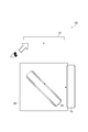
- FIGS. 7 is a diagram illustrating a configuration of the collimation evaluation apparatus 3 according to the third embodiment.
- FIG. 8 is a diagram illustrating a configuration of the collimation evaluation apparatus 4 according to the fourth embodiment.
- FIGS. 9A and 9B are diagrams showing the configuration of the collimation evaluation apparatus 5 according to the fifth embodiment.
- FIGS. 10A and 10B are diagrams for explaining an example of the operation of the collimation evaluation apparatus 5 according to the fifth embodiment.
- FIGS. 11A and 11B are diagrams illustrating an example of the operation of the collimation evaluation apparatus 5 according to the fifth embodiment.
- FIGS. 12A and 12B are diagrams for explaining another example of the operation of the collimation evaluation apparatus 5 according to the fifth embodiment.
- FIGS. 13A and 13B are diagrams for explaining another example of the operation of the collimation evaluation apparatus 5 according to the fifth embodiment.
- FIGS. 14A to 14C are photographs of interference fringes observed on the screen 30 of the collimation evaluation apparatus 5 according to the fifth embodiment.
- FIG. 15 is a diagram illustrating a configuration of a first modification of the collimation evaluation apparatus according to the first embodiment.
- FIG. 16 is a diagram illustrating a configuration of a second modification of the collimation evaluation apparatus according to the first embodiment.
- FIG. 17 is a diagram illustrating a configuration of a third modification of the collimation evaluation apparatus according to the first embodiment.
- FIG. 18 is a diagram illustrating a configuration of a fourth modification of the collimation evaluation apparatus of the first embodiment.
- FIG. 1 is a diagram illustrating a configuration of a collimation evaluation apparatus 100 of a comparative example.
- the collimation evaluation apparatus 100 of the comparative example includes a reflecting member 20, a screen 30, and a housing 40.
- the reflecting member 20 and the screen 30 are fixed to the housing 40. It is assumed that the direction in which the collimation evaluation target light L 0 is incident on the collimation evaluation apparatus 100 is parallel to the x-axis.
- the reflecting member 20 is a shear plate made of a transparent flat plate having a first reflecting surface 21 and a second reflecting surface 22 facing each other.
- the material of the transparent flat plate is, for example, BK7 or synthetic quartz.
- the reflecting member 20 is disposed so as to reflect the light L 0 incident parallel to the x axis and emit the reflected light parallel to the z axis.
- the flatness of the first reflecting surface 21 and the second reflecting surface 22 is about a fraction of the wavelength of the evaluation target light.
- the first reflecting surface 21 and the second reflecting surface 22 are not parallel to each other, and the distance between the reflecting surfaces changes along the direction parallel to the y-axis, and is about several seconds to several tens of seconds. (Wedge angle).
- the screen 30 is a ground glass plate arranged so as to be parallel to both the x-axis and the y-axis. Reflected light components L 1 and L 2 reflected by the first reflecting surface 21 and the second reflecting surface 22 of the reflecting member 20 are incident on the screen 30. Interference fringes are formed on the screen 30 by these two light components L 1 and L 2 , and the interference fringes can be observed.
- the evaluation target light L 0 is incident parallel to the reflecting member 20 to the x-axis.
- a part of the incident light L 0 is reflected by the first reflecting surface 21, and the reflected light L 1 enters the screen 30 in parallel with the z axis.
- the light transmitted through the first reflecting surface 21 is reflected by the second reflecting surface 22, and the reflected light L 2 enters the screen 30 parallel to the z axis.
- the reflected light component L 1 and the reflected light component L 2 incident on the screen 30 are shifted from each other in the direction parallel to the x-axis by an interval corresponding to the thickness of the reflecting member 20, and the thickness of the reflecting member 20 is increased.
- a corresponding optical path length difference is generated.
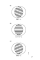
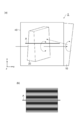
- FIG. 2 is a diagram illustrating interference fringes formed on the screen 30 of the collimation evaluation apparatus 100 of the comparative example.
- the interference fringes formed on the screen 30 are caused by the components caused by the first reflecting surface 21 and the second reflecting surface 22 of the reflecting member 20 being non-parallel to each other and the non-parallel nature of the incident light L 0.
- the interference fringes formed on the screen 30 include only components resulting from the first reflecting surface 21 and the second reflecting surface 22 being non-parallel to each other. Since the component due to the non-parallel property of the light L 0 is not included, it is parallel to the x-axis as shown in FIG.
- the interference fringes formed on the screen 30 are added to the components caused by the first reflecting surface 21 and the second reflecting surface 22 being non-parallel to each other.
- it since it also includes a component due to non-parallelism of the incident light L 0 , it is inclined with respect to the x-axis as shown in FIGS.
- the direction of inclination from one another The reverse is true.
- the collimation evaluation apparatus 100 of the comparative example in order to detect with high sensitivity the change in the direction of the interference fringes with respect to the reference line on the screen 30, it is desirable to increase the thickness of the reflective member 20 that is a shear plate. .
- the thickness of the reflective member 20 the optical path length difference between the reflected light L 1 that reaches the screen 30 and the reflected light L 2 is increased.
- it is able to observe interference fringes on the screen 30 is when the optical path length difference from the coherence length of the evaluation object light L 0 is short.
- the thickness of the reflecting member 20 is increased to improve the sensitivity, the optical path length difference increases, and it becomes impossible to perform collimation evaluation of light having a coherence distance shorter than the optical path length difference.
- the collimation evaluation apparatus 100 of the comparative example it is difficult to evaluate light collimation with a short coherence distance with high sensitivity.
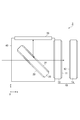
- FIG. 3 is a diagram illustrating a configuration of the collimation evaluation apparatus 1 according to the first embodiment.
- the collimation evaluation apparatus 1 according to the first embodiment includes a first reflecting member 10, a second reflecting member 20, a screen 30, and a housing 40.
- the first reflecting member 10, the second reflecting member 20, and the screen 30 are fixed to the housing 40. It is assumed that the direction in which the collimation evaluation target light L 0 is incident on the collimation evaluation apparatus 1 is parallel to the x-axis.
- the first reflecting member 10 is a transparent flat plate having a first reflecting surface 11 that reflects part of incident light and a second reflecting surface 12 that reflects light that has passed through the first reflecting surface 11 out of the light. It is.
- the second reflecting member 20 is a transparent flat plate having a first reflecting surface 21 that reflects a part of incident light and a second reflecting surface 22 that reflects light transmitted through the first reflecting surface 21 out of the light. It is.
- the material of these transparent flat plates is, for example, BK7 or synthetic quartz.
- the first reflecting member 10 When light that is incident in parallel to the x-axis and passes through the second reflecting member 20 is incident, the first reflecting member 10 reflects a part of the light on the first reflecting surface 11, and first reflection of the light is performed. The light transmitted through the surface 11 is reflected by the second reflecting surface 12 so that these reflected light components are emitted in the opposite direction.
- the second reflective member 20 When the light emitted from the first reflective member 10 is incident, the second reflective member 20 reflects a part of the light on the first reflective surface 21 and transmits the light transmitted through the first reflective surface 21 out of the light.
- the two reflection surfaces 22 reflect the reflected light components so that these reflected light components are emitted in parallel to the z-axis.
- each of the reflection surfaces 11, 12, 21, and 22 is about a fraction of the wavelength of the evaluation target light.
- the 1st reflective surface 11 and the 2nd reflective surface 12 are mutually parallel.
- the first reflecting surface 21 and the second reflecting surface 22 are not parallel to each other, and the distance between the reflecting surfaces is changed along the direction parallel to the y-axis.
- This is a shear plate whose reflecting surface forms an angle (wedge angle) of several seconds to several tens of seconds.
- the screen 30 is a ground glass plate arranged so as to be parallel to both the x-axis and the y-axis.
- the light reflected by the first reflecting surface 11 of the first reflecting member 10 and the first reflecting surface 21 of the second reflecting member 20 is denoted as L 11 .
- the light reflected by the second reflecting surface 22 of the first reflecting surface 11 and the second reflecting member 20 of the first reflecting member 10 is represented as L 12.
- the light reflected by the second reflecting surface 12 of the first reflecting member 10 and the first reflecting surface 21 of the second reflecting member 20 is denoted as L 21 .
- representative of the light reflected by the second reflecting surface 22 of the second reflecting surface 12 and the second reflecting member 20 of the first reflecting member 10 and L 22 are incident on the screen 30.
- interference fringes are formed by interference between those reflected light components L 11 , L 12 , L 21 , and L 22 having optical path length differences smaller than the coherence distance. Observable.
- the screen 30 is an observation unit that makes interference fringes observable.
- the direction of interference fringes caused by the first reflecting surface 21 and the second reflecting surface 22 of the second reflecting member 20 being non-parallel to each other and the direction of interference fringes caused by non-parallelism of incident light are: They are different from each other.
- the magnitude relationship between the optical path lengths of the reflected light components L 11 , L 12 , L 21 , and L 22 is as follows.
- the optical path lengths of these reflected light components differ depending on whether or not the light reciprocates between the first reflecting surface 11 and the second reflecting surface 12 of the first reflecting member 10, and the second reflecting member 20 has the first path length. It also differs depending on whether or not light reciprocates between the first reflecting surface 21 and the second reflecting surface 22. Accordingly, the optical path length of the reflected light component L 11 is short and the optical path length of the reflected light component L 22 is longer than the optical path lengths of the reflected light components L 12 and L 21 .
- the optical path length of each reflected light component L 12, L 21 can be comparable, reflected light component L 12, L 21 Can be made smaller than the coherence distance. That is, the light L 12 reflected by the first reflecting surface 11 of the first reflecting member 10 and the second reflecting surface 22 of the second reflecting member 20, and the second reflecting surface 12 and the second reflecting member 20 of the first reflecting member 10. Interference fringes can be formed on the screen 30 by the light L 21 reflected by the first reflecting surface 21.
- a reference line is drawn on the screen 30.
- the interference fringes are parallel to the reference line, it can be determined that the incident light is collimated light, and the incident light is diverged by the inclination of the interference fringes with respect to the reference line. Or it can determine with it being convergent light.
- the first reflection member 10 as described above using a second reflecting member 20 and the screen 30, both lights in screen 30 on which the reflected light component L 12 and the reflected light component L 21 is incident
- the interference fringes formed by the components are observed, and the collimation of the incident light is evaluated based on the observed direction of the interference fringes.
- the reflected light components L 12 , L 12 even when the thickness of the second reflecting member 20 is large in order to improve sensitivity, and even when the coherence distance of the light to be collimated is short. Since the optical path length difference of L 21 can be made smaller than the coherence distance, the collimation of the light can be evaluated with high sensitivity.
- the collimation evaluation apparatus 1 of the present embodiment has a configuration equivalent to that of the collimation evaluation apparatus 100 of the comparative example (that is, a configuration including the second reflecting member 20, the screen 30, and the housing 40). This corresponds to a case in which the incident direction of the light to be evaluated is reversed after adding one reflecting member 10.
- the first reflective member 10 for correcting the optical path length difference is attached to the commercially available collimation evaluation apparatus, thereby the present embodiment.
- the collimation evaluation apparatus 1 can be configured.
- a mounting method a method of attaching the first reflecting member 10 to a case of a commercially available collimation evaluation apparatus with an adhesive or an adhesive tape, and a method of attaching the first reflecting member to a case of a commercially available collimation evaluation apparatus using a holder having an adjustment mechanism.
- FIG. 4 is a diagram illustrating a configuration of the collimation evaluation apparatus 2 according to the second embodiment. Compared with the configuration of the collimation evaluation apparatus 1 of the first embodiment shown in FIG. 3, the collimation evaluation apparatus 2 of the second embodiment shown in FIG. 4 is different in the configuration of the first reflecting member 10.
- the first reflecting member 10 in the second embodiment includes a first flat plate 13 having a first reflecting surface 11 and a second flat plate 14 having a second reflecting surface 12 arranged in parallel to the first flat plate 13.
- the first reflecting surface 11 of the first flat plate 13 and the second reflecting surface 12 of the second flat plate 14 are opposed to each other and are parallel to each other. It is preferable that a reflection reducing film is formed on the surface of the first flat plate 13 opposite to the first reflecting surface 11. Further, it is preferable that a reflection reducing film is also formed on the surface of the second flat plate 14 opposite to the second reflecting surface 12.
- the second embodiment also operates in the same manner as the first embodiment and has the same effects.
- the interval between the first flat plate 13 and the second flat plate 14 is variable, that is, the interval between the first reflecting surface 11 and the second reflecting surface 12 is variable. It is. By doing so, the optical path length difference between the reflected light components L 12 and L 21 incident on the screen 30 can be adjusted, and the optical path length difference can be set according to the coherence distance of light.
- a moving mechanism In order to make the distance between the first flat plate 13 and the second flat plate 14 variable, a moving mechanism is provided that moves either or both of the first flat plate 13 and the second flat plate 14 in a direction parallel to the x-axis. Just do it.
- a stage having a high positional accuracy or an annular shim is preferably used.
- the collimation evaluation target light is laser light having a wavelength of 1080 nm and a coherence distance of 0.6 mm, which is emitted from the end face of the optical fiber laser light source, and is incident on the collimation evaluation apparatus 2 through the lens.
- the distance between the first flat plate 13 and the second flat plate 14 (that is, the distance between the first reflecting surface 11 and the second reflecting surface 12) is different by 0.20 mm in the range of 2.95 mm to 3.95 mm.
- the interference fringes formed on the screen 30 at each interval were photographed.
- FIG. 5A is a photograph of interference fringes when the spacing is 2.95 mm
- FIG. 5B is a photograph of interference fringes when the spacing is 3.15 mm
- FIG. 5C is 3.35 mm spacing. It is a photograph of the interference fringes in the case of.
- FIG. 6A is a photograph of interference fringes when the spacing is 3.55 mm
- FIG. 6B is a photograph of interference fringes when the spacing is 3.75 mm
- FIG. 6C is a spacing of 3.95 mm. It is a photograph of the interference fringes in the case of.
- the distance between the first flat plate 13 and the second flat plate 14 of the first reflecting member 10 is set according to the thickness of the second reflecting member 20 so that the length difference cancels.
- FIG. 7 is a diagram illustrating a configuration of the collimation evaluation apparatus 3 according to the third embodiment.
- the collimation evaluation apparatus 3 according to the third embodiment includes a first reflecting member 10, a second reflecting member 20, a screen 30 and a housing 40.
- the first reflecting member 10, the second reflecting member 20, and the screen 30 are fixed to the housing 40. It is assumed that the direction in which the collimation evaluation target light enters the collimation evaluation apparatus 3 is parallel to the z axis.
- the first reflecting member 10, the second reflecting member 20, and the screen 30 in the third embodiment are the same as those in the first embodiment, but are different from the first embodiment in arrangement.
- the first reflecting member 10 When light is incident in parallel to the z axis, the first reflecting member 10 reflects a part of the light on the first reflecting surface 11, and the light that has passed through the first reflecting surface 11 out of the light is reflected on the second reflecting surface. 12 so that these reflected light components are emitted in a direction parallel to the x-axis.
- the second reflective member 20 reflects a part of the light on the first reflective surface 21 and transmits the light transmitted through the first reflective surface 21 out of the light.
- the two reflection surfaces 22 reflect the reflected light components so that these reflected light components are emitted in parallel to the z-axis.
- the screen 30 is a ground glass plate arranged so as to be parallel to both the x-axis and the y-axis.
- the reflected light components L 11 , L 12 , L 21 and L 22 are incident on the screen 30.
- the optical path lengths of the reflected light components L 12 and L 21 can be made similar, and the reflected light component The optical path length difference between L 12 and L 21 can be made smaller than the coherent distance. That is, the light L 12 reflected by the first reflecting surface 11 of the first reflecting member 10 and the second reflecting surface 22 of the second reflecting member 20, and the second reflecting surface 12 and the second reflecting member 20 of the first reflecting member 10. Interference fringes can be formed on the screen 30 by the light L 21 reflected by the first reflecting surface 21.
- the reflected light component L 12 even when the thickness of the second reflecting member 20 is large in order to improve sensitivity, and even when the coherence distance of the light to be collimated is short. since the optical path length difference L 21 can be made smaller than the coherence length, it is possible to evaluate the optical collimation sensitivity.
- the evaluation target light is incident on the first reflecting member 10 after passing through the second reflecting member 20, and thus loses when passing through the second reflecting member 20.
- the evaluation target light can be directly incident on the first reflecting member 10 without being transmitted through the second reflecting member 20. There is no loss.
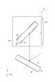
- FIG. 8 is a diagram illustrating a configuration of the collimation evaluation apparatus 4 according to the fourth embodiment. Compared with the configuration of the collimation evaluation apparatus 3 of the third embodiment shown in FIG. 7, the collimation evaluation apparatus 4 of the fourth embodiment shown in FIG. 8 is different in the arrangement of the first reflecting member 10.
- the first reflecting surface 11 and the second reflecting surface 12 are arranged so as to be inclined by 45 degrees with respect to both the x axis and the z axis, and the incident angle of light and Both reflection angles were 45 degrees.
- the first reflecting surface 11 and the second reflecting surface 12 are arranged so as to be rotatable around an axis parallel to the y axis. The angle and the emission angle are variable.
- the direction of the light which injects into the 1st reflective member 10 is set so that the light reflected by the 1st reflective member 10 may radiate
- the optical path length difference between the first reflected light component generated upon reflection at the reflecting member 10 L 12, L 21, of the second reflected light component generated upon reflection at the reflecting member 20 L 12, L 21 The orientation of the first reflecting member 10 is adjusted according to the thickness of the second reflecting member 20 so that the optical path length difference cancels out.
- the azimuth of the first reflecting member 10 it is possible to adjust the optical path length difference between the reflected light components L 12 and L 21 that are generated when the first reflecting member 10 is reflected.
- the orientation of the first reflecting member 10 is changed.
- the optical path length difference between the reflected light components L 12 and L 21 can be made smaller than the coherence distance, so that the collimation of the light can be evaluated with high sensitivity.
- FIG. 9 is a diagram illustrating a configuration of the collimation evaluation apparatus 5 according to the fifth embodiment.
- FIG. 9A is a top view seen in a direction parallel to the z-axis (a direction perpendicular to the screen 30).
- FIG. 9B is a side view seen in a direction parallel to the y-axis. In FIG. 9A, illustration of the screen 30 is omitted.
- the first reflecting surface 11 and the second reflecting surface 12 of the first reflecting member 10 are parallel to each other.
- the 1st reflective surface 11 and the 2nd reflective surface 12 of the 1st reflective member 10 are mutually non-parallel, and are the distance between both reflective surfaces along one direction. Has changed, forming an angle (wedge angle) of several seconds to several tens of seconds. That is, in the fifth embodiment, both the first reflecting member 10 and the second reflecting member 20 are shear plates.
- the first reflecting member 10 is disposed so as to be rotatable around an axis perpendicular to the x axis.
- FIGS. 10B and 11B are diagrams illustrating an example of the operation of the collimation evaluation apparatus 5 according to the fifth embodiment.
- FIG. 10A and FIG. 11A is a top view of the collimation evaluation apparatus 5 of the fifth embodiment.
- FIGS. 10B and 11B are diagrams showing interference fringes observed in the case of FIG. 10A corresponding to FIG. In these figures, the screen 30 is not shown.
- the distance between the first reflecting surface 21 and the second reflecting surface 22 of the second reflecting member 20 becomes narrower as it proceeds in the + y direction.
- the distance between the first reflecting surface 11 and the second reflecting surface 12 is also narrowed in the first reflecting member 10 as it proceeds in the + y direction. That is, the wedge directions of the first reflecting member 10 and the second reflecting member 20 are the same. In this case, as shown in FIG. 10B, the interval between the interference fringes becomes wide.
- the distance between the first reflecting surface 11 and the second reflecting surface 12 is increased as it proceeds in the + y direction. That is, the wedge directions of the first reflecting member 10 and the second reflecting member 20 are opposite to each other. In this case, as shown in FIG. 11B, the interval between the interference fringes becomes narrow.
- the interval between the interference fringes depends on the sum of the wedge angles of the first reflecting member 10 and the second reflecting member 20, and also depends on the wavelength of light to be collimated.
- the wedge angle of the first reflection member 10 and theta 1, the wedge angle of the second reflecting member 20 and theta 2, eg, ⁇ 1 ⁇ 2/3.
- the entire wedge angle when the first reflection member 10 and the second reflecting member 20 each wedge directions are opposite to each other becomes 2 [Theta] 2/3.
- Overall wedge angle 4? 2/3 next to the case where the first reflecting member 10 and the second reflecting member 20 each wedge directions are the same to each other, and 2 times the overall wedge angle when the wedge direction are opposite to each other Become.
- FIG. 12 and 13 are diagrams illustrating another example of the operation of the collimation evaluation apparatus 5 according to the fifth embodiment.
- FIG. 12A and FIG. 13A is a top view of the collimation evaluation apparatus 5 of the fifth embodiment.
- FIG. 12B and FIG. 13B is a diagram illustrating interference fringes observed in the case of FIG. In these drawings, the screen 30 is not shown, but a reference line A drawn on the screen 30 is shown.
- the distance between the first reflecting surface 21 and the second reflecting surface 22 of the second reflecting member 20 becomes narrower as it proceeds in the substantially + y direction, but the accuracy of attachment to the housing 40 is insufficient.
- the wedge direction is somewhat inclined from the y direction.
- the distance between the first reflecting surface 11 and the second reflecting surface 12 is increased as it advances in the + y direction, and the wedge direction is accurately set in the y direction. It has become. In this case, even if the evaluation target light is good collimated light, the interference fringes are inclined with respect to the reference line A as shown in FIG.
- the first reflecting member 10 has a gap between the first reflecting surface 21 and the second reflecting surface 22 that increases in the substantially + y direction, but the wedge direction is the y direction. It is somewhat inclined from.
- the inclination of the first reflecting member 10 in the wedge direction is set so as to cancel the inclination of the second reflecting member 20 in the wedge direction.
- the interference fringes are parallel to the reference line A as shown in FIG.
- the wedge direction of the second reflecting member 20 is slightly inclined from the y direction due to insufficient accuracy of the attachment of the second reflecting member 20 to the housing 40.
- the collimation of the evaluation target light can be accurately evaluated.
- FIG. 14 is a photograph of interference fringes observed on the screen 30 of the collimation evaluation apparatus 5 of the fifth embodiment.
- the collimation evaluation target light is laser light having a wavelength of 1080 nm and a coherence distance of 0.6 mm, which is emitted from the end face of the optical fiber laser light source, and is incident on the collimation evaluation apparatus 5 through the lens.
- the wedge direction of the first reflecting member 10 was varied by 90 degrees, and the interference fringes formed on the screen 30 in each wedge direction were photographed.
- FIG. 14B shows that the wedge direction of the first reflecting member 10 is rotated by 90 degrees.
- FIG. 14C shows the interference fringes when the wedge direction of the first reflecting member 10 is rotated by 180 degrees.
- FIGS. 15 to 18 are diagrams showing a configuration of a modification of the collimation evaluation apparatus 1 of the first embodiment. In these modified examples, another configuration is adopted as an observation unit for making interference fringes observable.
- the collimation evaluation apparatus 1A of the first modified example shown in FIG. 15 uses the reflective screen 31 as an observation unit, and observes the interference fringes by the light reflected and diffused by the screen 30. This configuration is suitable from the viewpoint of observer safety when observing interference fringes of high-intensity light.
- the collimation evaluation apparatus 1B of the second modification shown in FIG. 16 observes the interference fringes by displaying the interference fringes imaged by the camera 32 on the display device using the camera 32 as an observation unit.
- interference fringes can be observed even with light in a wavelength region other than visible light (ultraviolet region, infrared region, etc.).
- the collimation evaluation apparatus 1C of the third modification shown in FIG. 17 uses the lens 33 and the camera 32 as an observation unit, images an interference fringe enlarged or reduced by the lens 33 with the camera 32, and picks up the captured interference fringe. Is displayed on the display device to observe interference fringes. In the case of this configuration, interference fringes can be observed even with light in a wavelength region other than visible light, and interference fringes can be observed in a desired field of view by changing the magnification.
- the collimation evaluation apparatus 1D of the fourth modified example shown in FIG. 18 uses a transmissive screen 30, a lens 33, and a camera 32 as an observation unit, and enlarges or reduces interference fringes on the screen 30 with the lens 33.
- the interference fringes are observed by picking up an image by 32 and displaying the picked-up interference fringes on the display device. Also in this configuration, interference fringes can be observed even with light in a wavelength region other than visible light, and interference fringes with a desired interval can be observed by changing the magnification. Further, the inclination of the interference fringes with respect to the reference line drawn on the screen 30 can be confirmed.
- the collimation evaluation apparatuses 1B and 1C that do not use the screen cannot use the reference line on the screen, but can use the electronic line of the camera 32 as the reference line.
- collimation evaluation apparatuses 1A to 1D are modifications of the collimation evaluation apparatus 1 of the first embodiment, but similar modifications are possible in the collimation evaluation apparatuses 2 to 5 of other embodiments.
- the first reflecting surface 11 and the second reflecting surface 12 of the first reflecting member 10 are parallel to each other, and the first reflecting surface 21 of the second reflecting member 20 and The second reflecting surface 22 is assumed to be non-parallel to each other.
- the first reflecting surface 11 and the second reflecting surface 12 of the first reflecting member 10 are non-parallel to each other, and the first reflecting surface 21 and the second reflecting surface 22 of the second reflecting member 20 are. And may be parallel to each other. Further, in both the first reflecting member 10 and the second reflecting member 20, the first reflecting surface and the second reflecting surface may be non-parallel to each other.
- the direction of the interference fringes caused by the first reflecting surface and the second reflecting surface being non-parallel to each other and / or the first reflecting member 10 and / or the second reflecting member 20
- the first reflecting member 10 and the second reflecting member 20 are arranged so that the directions of the interference fringes resulting from the non-parallelism of light are different from each other.
- the light L 12 reflected by the first reflecting surface 11 of the first reflecting member 10 and the second reflecting surface 22 of the second reflecting member 20 and the second reflecting surface 12 and the second reflecting member 20 of the first reflecting member 10 are reflected.
- the interference fringes formed by the light L 21 reflected by the first reflecting surface 21 are observed, and the collimation of the incident light can be evaluated based on the observed orientation of the interference fringes.
- the first reflecting member 10 is constituted by two flat plates, but the second reflecting member 20 may also be constituted by two flat plates.
- the first reflecting member 10 or the second reflecting member 20 is composed of two flat plates, by adjusting the spacing between the two flat plates, adjusting the optical path length difference between the reflected light component L 12, L 21 Can do.
- the wedge angle and the wedge direction of the reflecting member can be adjusted by adjusting the inclination of both or one of the two flat plates.
- a first reflection surface that reflects a part of incident light and a second reflection surface that reflects light that has passed through the first reflection surface of the incident light.
- a first reflecting member having (2) a first reflecting surface that reflects a part of the light emitted from the first reflecting member, and a second reflecting surface that reflects the light transmitted through the first reflecting surface of the light. And (3) a light component reflected by the first reflecting surface of the first reflecting member and the second reflecting surface of the second reflecting member, and the second reflecting surface of the first reflecting member.
- the collimation of incident light is evaluated based on the direction of interference fringes formed by the light component reflected by the first reflecting surface of the second reflecting member.
- a first reflecting member having (2) a first reflecting surface that reflects a part of the light emitted from the first reflecting member, and a second reflecting surface that reflects the light transmitted through the first reflecting surface of the light. And (a) the light component reflected by the first reflecting surface of the first reflecting member and the second reflecting surface of the second reflecting member, and the second reflecting surface of the first reflecting member.
- the interference fringes formed by the light component reflected by the first reflecting surface of the second reflecting member are observed, and (b) the collimation of the incident light is evaluated based on the observed orientation of the interference fringes.
- the first reflecting member and the second reflecting member are not parallel to each other in either or either of the first reflecting member and the second reflecting member.
- a configuration in which the orientation of interference fringes resulting from non-parallelism between the first reflecting surface and the second reflecting surface in both or any one of them and the orientation of interference fringes resulting from non-parallelism of incident light are different from each other It is preferable that
- the first reflecting member and the second reflecting member are not parallel to each other in either or either of the first reflecting member and the second reflecting member.
- the direction of interference fringes resulting from non-parallelism between the first reflecting surface and the second reflecting surface in both or either of the reflecting members and the direction of interference fringes resulting from non-parallelism of incident light It is preferable that the first reflecting member and the second reflecting member are arranged so as to be different from each other.
- the first reflection member and / or the second reflection member each include a flat plate having two surfaces facing each other as the first reflection surface and the second reflection surface. It is also good.
- the first reflection member and / or the second reflection member are arranged in parallel with the first flat plate having the first reflection surface and the first flat plate. It is good also as a structure containing the 2nd flat plate which has 2 reflective surfaces.
- the interval between the first flat plate and the second flat plate (that is, the interval between the first reflecting surface and the second reflecting surface) is variable. By appropriately setting this interval, the optical path length difference between the two reflected light components L 12 and L 21 can be adjusted, and the optical path length difference can be made smaller than the coherent distance. It can be evaluated with high sensitivity.
- the first reflection member and the second reflection member are nonparallel to each other in both the first reflection member and the second reflection member. Both or either of them may be rotatable around an axis substantially perpendicular to the first reflecting surface or the second reflecting surface. In this case, the interval between the interference fringes can be adjusted by adjusting the rotation position of the first reflecting member or the second reflecting member. Further, even if the accuracy of mounting one of the first reflecting member and the second reflecting member is insufficient, the collimation of incident light can be accurately evaluated by adjusting the rotational position of the other reflecting member. Can do.
- the signal intensity is reduced to the four surfaces of the reflecting surfaces 21 and 22, or the reflecting surfaces 11 and 12, or the reflecting surfaces 21, 22, 11, and 12.
- a coating for reducing the reflectance may be provided.
- the reflectances of the reflecting surfaces 21 and 22 and the reflectances of the reflecting surfaces 11 and 12 are approximately the same.
- a reflectance of about 1% can be realized on the glass surface and the glass back surface by laminating one layer each of aluminum oxide Al 2 O 3 and magnesium fluoride MgF 2 .
- the present invention can be used as an apparatus and a method that can evaluate collimation of light with high sensitivity even when the coherence distance of light subjected to collimation evaluation is short.
Landscapes
- Physics & Mathematics (AREA)
- Spectroscopy & Molecular Physics (AREA)
- General Physics & Mathematics (AREA)
- Chemical & Material Sciences (AREA)
- Analytical Chemistry (AREA)
- Instruments For Measurement Of Length By Optical Means (AREA)
- Testing Of Optical Devices Or Fibers (AREA)
- Length Measuring Devices By Optical Means (AREA)
Abstract
第1反射部材10は、第2反射部材20を透過した光が入射すると、該光の一部を第1反射面11で反射させ、該光のうち第1反射面11を透過した光を第2反射面12で反射させて、これらの反射光成分を逆方向に出射させる。第2反射部材20は、第1反射部材10から出射した光が入射すると、該光の一部を第1反射面21で反射させ、該光のうち第1反射面21を透過した光を第2反射面22で反射させて、これらの反射光成分を出射させる。第1反射部材10の第1反射面11および第2反射部材20の第2反射面22で反射した光L12と、第1反射部材10の第2反射面12および第2反射部材20の第1反射面21で反射した光L21とにより、スクリーン30上に干渉縞を形成する。これにより、光の可干渉距離が短い場合であっても該光のコリメーションを感度よく評価することができる装置及び方法が実現される。
Description
本発明は、光のコリメーションを評価する装置および方法に関するものである。
様々な光学システムにおいて点光源(点光源と見做し得るものを含む)から出射した発散光を平行光に変換する(コリメートする)ことの頻度は高い。点光源としては、例えば、レーザダイオード、光ファイバ出射端等が挙げられる。点光源とコリメート光学系との間の距離を適切に設定することで、点光源から出射した発散光をコリメート光学系により平行光に変換することができる。このようにして生成された平行光の平行度(コリメーションの程度)を評価する技術が特許文献1,2に記載されている。
その中でも、特許文献1に記載されている技術は、互いに非平行な第1反射面および第2反射面を有するシェアプレートを用いて、光のコリメーションを簡易に評価することができる。すなわち、シェアプレートを用いるコリメーション評価装置は、シェアプレートの第1反射面で反射した光と、シェアプレートの第1反射面を透過して第2反射面で反射した光とをスクリーン上で干渉させ、そのスクリーン上の干渉縞の方位に基づいて光のコリメーションを評価することができる。なお、シェアプレートはシェアリングプレートと呼ばれることもある。
上記のようなシェアプレートを用いるコリメーション評価装置では、スクリーン上の干渉縞の方位の変化を感度よく検出する為に、シェアプレートの厚みを大きくすることが望まれ、また、シェアプレートの2つの反射面が互いになす角度(ウエッジ角)を小さくすることが望まれる。そのうちウェッジ角は、干渉縞間隔に影響を与えるので、コリメーション評価に適した干渉縞間隔により或る程度決定される。したがって、感度の向上の為には、シェアプレートの厚みを大きくすることになる。
シェアプレートの2つの反射面それぞれで反射してスクリーンに到達するまでの両光成分の間には光路長差が生じる。シェアプレートの厚みが大きくほど、その光路長差は大きくなる。一方、スクリーン上で干渉縞を観測することができるのは、コリメーション評価対象の光の可干渉距離(コヒーレンス長)より光路長差が短い場合である。
例えば、HeNeレーザ光源から出力されるCWレーザ光の可干渉距離は100mmオーダーである。固体レーザ光源から出力されるパルス幅40nsのパルスレーザ光の可干渉距離は数mmである。また、光ファイバレーザ光源から出力されるパルス幅40nsのパルスレーザ光の可干渉距離は1mm以下である。一般に、固体レーザ光源や光ファイバレーザ光源から出力される短パルスのレーザ光は、マルチ縦モードやスペクトル拡がりにより、可干渉距離が短い。
感度の向上の為にシェアプレートの厚みを大きくすると、光路長差が大きくなって、この光路長差より可干渉距離が短い光のコリメーション評価をすることができなくなる。このように、従来では、シェアプレートを用いるコリメーション評価装置では、可干渉距離が短い光のコリメーションを感度よく評価することが困難であった。
本発明は、上記問題点を解消する為になされたものであり、コリメーション評価対象の光の可干渉距離が短い場合であっても該光のコリメーションを感度よく評価することができる装置および方法を提供することを目的とする。
本発明によるコリメーション評価装置は、(1)入射光の一部を反射させる第1反射面と、該入射光のうち該第1反射面を透過した光を反射させる第2反射面と、を有する第1反射部材と、(2)第1反射部材から出射した光の一部を反射させる第1反射面と、該光のうち該第1反射面を透過した光を反射させる第2反射面と、を有する第2反射部材と、を備え、(3)第1反射部材の第1反射面および第2反射部材の第2反射面で反射した光ならびに第1反射部材の第2反射面および第2反射部材の第1反射面で反射した光により形成される干渉縞の方位に基づいて入射光のコリメーションを評価することを特徴とする。
本発明によるコリメーション評価方法は、(1)入射光の一部を反射させる第1反射面と、該入射光のうち該第1反射面を透過した光を反射させる第2反射面と、を有する第1反射部材と、(2)第1反射部材から出射した光の一部を反射させる第1反射面と、該光のうち該第1反射面を透過した光を反射させる第2反射面と、を有する第2反射部材と、を用い、(a)第1反射部材の第1反射面および第2反射部材の第2反射面で反射した光ならびに第1反射部材の第2反射面および第2反射部材の第1反射面で反射した光により形成される干渉縞を観測し、(b)その観測した干渉縞の方位に基づいて入射光のコリメーションを評価することを特徴とする。
上記したコリメーション評価装置またはコリメーション評価方法では、コリメーション評価対象の光は、先ず第1反射部材に入射し、その光の一部が第1反射部材の第1反射面で反射し、この第1反射面を透過した光が第1反射部材の第2反射面で反射する。第1反射部材で反射した光は、次に第2反射部材に入射し、その光の一部が第2反射部材の第1反射面で反射し、この第1反射面を透過した光が第2反射部材の第2反射面で反射する。
これらの反射光成分のうち、第1反射部材の第1反射面および第2反射部材の第2反射面で反射した光L12と、第1反射部材の第2反射面および第2反射部材の第1反射面で反射した光L21との光路長差を、可干渉距離より小さくすることができるので、これら2つの光成分L12,L21による干渉縞を観測することができる。この観測した干渉縞の方位に基づいて入射光のコリメーションを評価することができる。
本発明によれば、コリメーション評価対象の光の可干渉距離が短い場合であっても、該光のコリメーションを感度よく評価することができる。
以下、添付図面を参照して、本発明を実施するための形態を詳細に説明する。なお、図面の説明において同一の要素には同一の符号を付し、重複する説明を省略する。また、各図には、説明の便宜の為にxyz直交座標系が示されている。
(比較例)
図1は、比較例のコリメーション評価装置100の構成を示す図である。比較例のコリメーション評価装置100は、反射部材20、スクリーン30および筐体40を備える。反射部材20およびスクリーン30は、筐体40に固定されている。コリメーション評価対象の光L0がコリメーション評価装置100に入射する方向はx軸に平行であるとする。
反射部材20は、互いに対向する第1反射面21および第2反射面22を有する透明平板からなるシェアプレートである。この透明平板の材料は例えばBK7や合成石英である。反射部材20は、x軸に平行に入射した光L0を反射させ当該反射光をz軸に平行に出射させるように配置されている。第1反射面21および第2反射面22の平面度は、評価対象光の波長の数分の1の程度とされている。第1反射面21と第2反射面22とは、互いに非平行であって、y軸に平行な方向に沿って両反射面の間の距離が変化しており、数秒~数十秒の程度の角度(ウエッジ角)をなしている。
スクリーン30は、x軸およびy軸の双方に平行となるように配置されたすりガラス板である。反射部材20の第1反射面21および第2反射面22それぞれで反射した反射光成分L1,L2がスクリーン30に入射する。これら2つの光成分L1,L2によりスクリーン30上に干渉縞が形成され、その干渉縞が観測可能とされる。
このコリメーション評価装置100では、評価対象光L0はx軸に平行に反射部材20に入射する。入射光L0の一部は第1反射面21で反射し、その反射光L1はz軸に平行にスクリーン30に入射する。入射光L0のうち第1反射面21を透過した光は第2反射面22で反射し、その反射光L2はz軸に平行にスクリーン30に入射する。スクリーン30に入射する反射光成分L1と反射光成分L2とは、反射部材20の厚みに応じた間隔だけx軸に平行な方向に互いにシフトしたものとなるとともに、反射部材20の厚みに応じた光路長差が生じることになる。
図2は、比較例のコリメーション評価装置100のスクリーン30上に形成される干渉縞を説明する図である。スクリーン30上に形成される干渉縞は、反射部材20の第1反射面21と第2反射面22とが互いに非平行であることに起因する成分と、入射光L0の非平行性に起因する成分とのベクトル和となる。
入射光L0がコリメート光である場合、スクリーン30上に形成される干渉縞は、第1反射面21と第2反射面22とが互いに非平行であることに起因する成分のみを含み、入射光L0の非平行性に起因する成分を含まないので、図2(b)に示されるようにx軸に平行になる。
入射光L0が発散光または収束光である場合、スクリーン30上に形成される干渉縞は、第1反射面21と第2反射面22とが互いに非平行であることに起因する成分に加えて、入射光L0の非平行性に起因する成分をも含むので、図2(a),(c)に示されるようにx軸に対して傾斜する。入射光L0が発散光であるときの干渉縞(図2(a))と、入射光L0が収束光であるときの干渉縞(図2(c))とは、傾斜の方向が互いに逆である。
このように、スクリーン30上に形成される干渉縞の方位に基づいて、入射光L0のコリメーションを評価することができ、また、光L0のコリメーションを調整することができる。なお、スクリーン30には基準線が描かれており、干渉縞が基準線に平行であるときに入射光L0がコリメート光であると判定することができる。
以上のような比較例のコリメーション評価装置100では、スクリーン30上の基準線に対する干渉縞の方位の変化を感度よく検出する為に、シェアプレートである反射部材20の厚みを大きくすることが望まれる。しかし、反射部材20の厚みが大きいほど、スクリーン30に到達する反射光L1と反射光L2との間の光路長差は大きくなる。一方、スクリーン30上で干渉縞を観測することができるのは、評価対象光L0の可干渉距離より光路長差が短い場合である。
感度の向上の為に反射部材20の厚みを大きくすると、光路長差が大きくなって、この光路長差より可干渉距離が短い光のコリメーション評価をすることができなくなる。このように、比較例のコリメーション評価装置100では、可干渉距離が短い光のコリメーションを感度よく評価することが困難である。
(第1実施形態)
図3は、第1実施形態のコリメーション評価装置1の構成を示す図である。第1実施形態のコリメーション評価装置1は、第1反射部材10、第2反射部材20、スクリーン30および筐体40を備える。第1反射部材10、第2反射部材20およびスクリーン30は、筐体40に固定されている。コリメーション評価対象の光L0がコリメーション評価装置1に入射する方向はx軸に平行であるとする。
第1反射部材10は、入射した光の一部を反射させる第1反射面11と、該光のうち第1反射面11を透過した光を反射させる第2反射面12と、を有する透明平板である。第2反射部材20は、入射した光の一部を反射させる第1反射面21と、該光のうち第1反射面21を透過した光を反射させる第2反射面22と、を有する透明平板である。これらの透明平板の材料は例えばBK7や合成石英である。
第1反射部材10は、x軸に平行に入射して第2反射部材20を透過した光が入射すると、該光の一部を第1反射面11で反射させ、該光のうち第1反射面11を透過した光を第2反射面12で反射させて、これらの反射光成分を逆方向に出射させるように配置されている。第2反射部材20は、第1反射部材10から出射した光が入射すると、該光の一部を第1反射面21で反射させ、該光のうち第1反射面21を透過した光を第2反射面22で反射させて、これらの反射光成分をz軸に平行に出射させるように配置されている。
反射面11,12,21,22それぞれの平面度は、評価対象光の波長の数分の1の程度とされている。第1反射部材10は、第1反射面11と第2反射面12とが互いに平行である。第2反射部材20は、第1反射面21と第2反射面22とが互いに非平行であって、y軸に平行な方向に沿って両反射面の間の距離が変化しており、両反射面が数秒~数十秒の程度の角度(ウエッジ角)をなしているシェアプレートである。
スクリーン30は、x軸およびy軸の双方に平行となるように配置されたすりガラス板である。ここで、第1反射部材10の第1反射面11および第2反射部材20の第1反射面21で反射した光をL11と表す。第1反射部材10の第1反射面11および第2反射部材20の第2反射面22で反射した光をL12と表す。第1反射部材10の第2反射面12および第2反射部材20の第1反射面21で反射した光をL21と表す。また、第1反射部材10の第2反射面12および第2反射部材20の第2反射面22で反射した光をL22と表す。これらの反射光成分L11,L12,L21,L22がスクリーン30に入射する。
スクリーン30上では、これらの反射光成分L11,L12,L21,L22のうち可干渉距離より小さい光路長差を有するもの同士が干渉することで干渉縞が形成され、その干渉縞が観測可能となる。スクリーン30は、干渉縞を可観測化する観測部である。第2反射部材20における第1反射面21と第2反射面22とが互いに非平行であることに起因する干渉縞の方位と、入射光の非平行性に起因する干渉縞の方位とは、互いに異なっている。
反射光成分L11,L12,L21,L22それぞれの光路長の大小関係は次のとおりである。これらの反射光成分の光路長は、第1反射部材10の第1反射面11と第2反射面12との間を光が往復するか否かによって異なり、また、第2反射部材20の第1反射面21と第2反射面22との間を光が往復するか否かによっても異なる。したがって、反射光成分L12,L21の光路長と比べて、反射光成分L11の光路長は短く、反射光成分L22の光路長は長い。
第1反射部材10および第2反射部材20それぞれの厚みを適切に設定すれば、反射光成分L12,L21それぞれの光路長を同程度とすることができ、反射光成分L12,L21の光路長差を可干渉距離より小さくすることができる。すなわち、第1反射部材10の第1反射面11および第2反射部材20の第2反射面22で反射した光L12と、第1反射部材10の第2反射面12および第2反射部材20の第1反射面21で反射した光L21とにより、スクリーン30上に干渉縞を形成することができる。
スクリーン30には基準線が描かれており、干渉縞が基準線に平行であるときに入射光がコリメート光であると判定することができ、基準線に対する干渉縞の傾斜によって入射光が発散光または収束光であると判定することができる。
本実施形態のコリメーション評価方法は、上記のような第1反射部材10、第2反射部材20およびスクリーン30を用い、反射光成分L12および反射光成分L21が入射したスクリーン30上において両光成分により形成される干渉縞を観測し、その観測した干渉縞の方位に基づいて入射光のコリメーションを評価する。
本実施形態では、感度向上の為に第2反射部材20の厚みが大きい場合であっても、また、コリメーション評価対象の光の可干渉距離が短い場合であっても、反射光成分L12,L21の光路長差を可干渉距離より小さくすることができるので、該光のコリメーションを感度よく評価することができる。
なお、本実施形態のコリメーション評価装置1は、比較例のコリメーション評価装置100と同等の構成(すなわち、第2反射部材20、スクリーン30および筐体40を備える構成)に光路長差補正用の第1反射部材10を加えた上で、評価対象光の入射方向を逆にしたものに相当する。
したがって、比較例のコリメーション評価装置100と同等の構成を有する市販のコリメーション評価装置があれば、その市販のコリメーション評価装置に光路長差補正用の第1反射部材10を取り付けることで、本実施形態のコリメーション評価装置1の構成とすることができる。その取り付け方としては、接着剤または接着テープにより市販のコリメーション評価装置の筐体に第1反射部材10を貼り付ける方法、調整機構を有するホルダにより市販のコリメーション評価装置の筐体に第1反射部材10を取り付ける方法、および、マグネットにより市販のコリメーション評価装置の筐体に第1反射部材10を着脱自在に取り付ける方法、等がある。
(第2実施形態)
図4は、第2実施形態のコリメーション評価装置2の構成を示す図である。図3に示された第1実施形態のコリメーション評価装置1の構成と比較すると、図4に示される第2実施形態のコリメーション評価装置2は、第1反射部材10の構成の点で相違する。
第2実施形態における第1反射部材10は、第1反射面11を有する第1平板13と、この第1平板13に対し並列配置され第2反射面12を有する第2平板14とを含む。第1平板13の第1反射面11と第2平板14の第2反射面12とは、互いに対向しており、互いに平行である。第1平板13の第1反射面11の反対側の面には反射低減膜が形成されているのが好適である。また、第2平板14の第2反射面12の反対側の面にも反射低減膜が形成されているのが好適である。
第2実施形態でも、第1実施形態と同様に動作し同様の効果を奏する。また、第2実施形態では、第1平板13と第2平板14との間の間隔が可変、すなわち、第1反射面11と第2反射面12との間の間隔が可変であるのが好適である。このようにすることにより、スクリーン30に入射する反射光成分L12,L21の光路長差を調整することができ、光の可干渉距離に応じて該光路長差を設定することができる。
第1平板13と第2平板14との間の間隔を可変とするには、第1平板13および第2平板14の双方または何れか一方をx軸に平行な方向に移動させる移動機構を設ければよい。このような移動機構として高い位置精度を有するステージや環状のシムが好適に用いられる。
図5および図6は、第2実施形態のコリメーション評価装置2のスクリーン30上で観察された干渉縞の写真である。コリメーション評価対象の光は、光ファイバレーザ光源の光ファイバ端面から出射された波長1080nmで可干渉距離0.6mmのレーザ光であって、レンズを介してコリメーション評価装置2に入射した。第1平板13と第2平板14との間の間隔(すなわち、第1反射面11と第2反射面12との間の間隔)を2.95mm~3.95mmの範囲において0.20mmずつ異ならせて、各々の間隔の場合にスクリーン30に形成された干渉縞を撮影した。
図5(a)は間隔2.95mmの場合の干渉縞の写真であり、図5(b)は間隔3.15mmの場合の干渉縞の写真であり、図5(c)は間隔3.35mmの場合の干渉縞の写真である。図6(a)は間隔3.55mmの場合の干渉縞の写真であり、図6(b)は間隔3.75mmの場合の干渉縞の写真であり、図6(c)は間隔3.95mmの場合の干渉縞の写真である。
これらの写真から判るように、第1平板13と、第2平板14との間の間隔が3.55mmである場合(図6(a))に、スクリーン30に入射する反射光成分L12,L21の光路長差を最小にすることができ、干渉縞のコントラストは最も良好なものとなる。また、間隔が3.55mmより大きくなるに従って又は小さくなるに従って、干渉縞のコントラストは悪化していく。
このように、第1反射部材10における反射の際に生じる反射光成分L12,L21の光路長差と、第2反射部材20における反射の際に生じる反射光成分L12,L21の光路長差とが相殺するように、第2反射部材20の厚みに応じて、第1反射部材10の第1平板13と第2平板14との間の間隔を設定する。これにより、感度向上の為に第2反射部材20の厚みが大きい場合であっても、また、コリメーション評価対象の光の可干渉距離が短い場合であっても、第1平板13と第2平板14との間の間隔を適切に設定することで、反射光成分L12,L21の光路長差を可干渉距離より小さくすることができるので、該光のコリメーションを感度よく評価することができる。
(第3実施形態)
図7は、第3実施形態のコリメーション評価装置3の構成を示す図である。第3実施形態のコリメーション評価装置3は、第1反射部材10、第2反射部材20、スクリーン30および筐体40を備える。第1反射部材10、第2反射部材20およびスクリーン30は、筐体40に固定されている。コリメーション評価対象の光がコリメーション評価装置3に入射する方向はz軸に平行であるとする。
第3実施形態における第1反射部材10、第2反射部材20およびスクリーン30は、第1実施形態と同様のものであるが、配置の点で第1実施形態と相違している。第1反射部材10は、z軸に平行に光が入射すると、該光の一部を第1反射面11で反射させ、該光のうち第1反射面11を透過した光を第2反射面12で反射させて、これらの反射光成分をx軸に平行な方向に出射させるように配置されている。第2反射部材20は、第1反射部材10から出射した光が入射すると、該光の一部を第1反射面21で反射させ、該光のうち第1反射面21を透過した光を第2反射面22で反射させて、これらの反射光成分をz軸に平行に出射させるように配置されている。
スクリーン30は、x軸およびy軸の双方に平行となるように配置されたすりガラス板である。反射光成分L11,L12,L21,L22がスクリーン30に入射する。本実施形態でも、第1反射部材10および第2反射部材20それぞれの厚みを適切に設定すれば、反射光成分L12,L21それぞれの光路長を同程度とすることができ、反射光成分L12,L21の光路長差を可干渉距離より小さくすることができる。すなわち、第1反射部材10の第1反射面11および第2反射部材20の第2反射面22で反射した光L12と、第1反射部材10の第2反射面12および第2反射部材20の第1反射面21で反射した光L21とにより、スクリーン30上に干渉縞を形成することができる。
本実施形態でも、感度向上の為に第2反射部材20の厚みが大きい場合であっても、また、コリメーション評価対象の光の可干渉距離が短い場合であっても、反射光成分L12,L21の光路長差を可干渉距離より小さくすることができるので、該光のコリメーションを感度よく評価することができる。
第1実施形態では、評価対象光は、第2反射部材20を透過した後に第1反射部材10に入射するので、第2反射部材20を透過する際に損失を受ける。これに対して、第3実施形態では、評価対象光は、第2反射部材20を透過することなく直接に第1反射部材10に入射することができるので、第2反射部材20の透過に因る損失がない。
(第4実施形態)
図8は、第4実施形態のコリメーション評価装置4の構成を示す図である。図7に示された第3実施形態のコリメーション評価装置3の構成と比較すると、図8に示される第4実施形態のコリメーション評価装置4は、第1反射部材10の配置の点で相違する。
第3実施形態における第1反射部材10は、第1反射面11および第2反射面12がx軸およびz軸の双方に対して45度だけ傾斜して配置されており、光の入射角および反射角の双方が45度であった。これに対して、第4実施形態における第1反射部材10は、第1反射面11および第2反射面12がy軸に平行な軸の周りに回動自在に配置されており、光の入射角および出射角が可変である。また、第4実施形態では、第1反射部材10で反射した光がx軸に平行に出射するように、第1反射部材10に入射する光の方向が設定される。
本実施形態では、第1反射部材10における反射の際に生じる反射光成分L12,L21の光路長差と、第2反射部材20における反射の際に生じる反射光成分L12,L21の光路長差とが相殺するように、第2反射部材20の厚みに応じて、第1反射部材10の方位を調整する。第1反射部材10の方位を調整することにより、第1反射部材10における反射の際に生じる反射光成分L12,L21の光路長差を調整することができる。これにより、感度向上の為に第2反射部材20の厚みが大きい場合であっても、また、コリメーション評価対象の光の可干渉距離が短い場合であっても、第1反射部材10の方位を調整することで、反射光成分L12,L21の光路長差を可干渉距離より小さくすることができるので、該光のコリメーションを感度よく評価することができる。
(第5実施形態)
図9は、第5実施形態のコリメーション評価装置5の構成を示す図である。図9(a)は、z軸に平行な方向(スクリーン30に垂直な方向)に見た上面図である。図9(b)は、y軸に平行な方向に見た側面図である。図9(a)ではスクリーン30の図示を省略している。
図3に示された第1実施形態のコリメーション評価装置1の構成と比較すると、図9に示される第5実施形態のコリメーション評価装置5は、第1反射部材10の構成の点で相違する。
第1実施形態では、第1反射部材10の第1反射面11と第2反射面12とは互いに平行である。これに対して、第5実施形態では、第1反射部材10の第1反射面11と第2反射面12とは、互いに非平行であって、一方向に沿って両反射面の間の距離が変化しており、数秒~数十秒の程度の角度(ウエッジ角)をなしている。すなわち、第5実施形態では、第1反射部材10および第2反射部材20の双方がシェアプレートである。また、第5実施形態では、第1反射部材10は、x軸に垂直な軸の周りに回動自在に配置されているのが好適である。
図10および図11は、第5実施形態のコリメーション評価装置5の作用の一例を説明する図である。図10(a)及び図11(a)それぞれは、第5実施形態のコリメーション評価装置5の上面図である。また、図10(b)及び図11(b)それぞれは、対応する図の(a)の場合に観測される干渉縞を示す図である。これらの図でもスクリーン30の図示を省略している。
何れの場合も、第2反射部材20は、+y方向に進むに従って第1反射面21と第2反射面22との間隔が狭くなっている。
図10(a)に示される例では、第1反射部材10も、+y方向に進むに従って第1反射面11と第2反射面12との間隔が狭くなっている。すなわち、第1反射部材10および第2反射部材20それぞれのウェッジ方向は互いに同じである。この場合、図10(b)に示されるように干渉縞の間隔は広くなる。
図11(a)に示される例では、第1反射部材10は、+y方向に進むに従って第1反射面11と第2反射面12との間隔が広くなっている。すなわち、第1反射部材10および第2反射部材20それぞれのウェッジ方向は互いに反対である。この場合、図11(b)に示されるように干渉縞の間隔は狭くなる。
干渉縞の間隔は、第1反射部材10および第2反射部材20それぞれのウェッジ角の和に依存し、また、コリメーション評価対象の光の波長に依存する。第1反射部材10のウェッジ角をθ1とし、第2反射部材20のウェッジ角をθ2とし、例えば θ1=θ2/3 とする。このとき、第1反射部材10および第2反射部材20それぞれのウェッジ方向が互いに反対である場合の全体のウェッジ角は2θ2/3となる。第1反射部材10および第2反射部材20それぞれのウェッジ方向が互いに同じである場合の全体のウェッジ角は4θ2/3となり、ウェッジ方向が互いに反対である場合の全体のウェッジ角の2倍となる。
したがって、或る波長λの光のコリメーションを評価する場合に第1反射部材10および第2反射部材20それぞれのウェッジ方向を互いに同じにし、第2高調波λ/2の光のコリメーションを評価する場合に第1反射部材10および第2反射部材20それぞれのウェッジ方向を互いに反対にすれば、両者の場合で互いに同じ干渉縞の間隔とすることができる。
図12および図13は、第5実施形態のコリメーション評価装置5の作用の他の一例を説明する図である。図12(a)及び図13(a)それぞれは、第5実施形態のコリメーション評価装置5の上面図である。図12(b)及び図13(b)それぞれは、対応する図の(a)の場合に観測される干渉縞を示す図である。これらの図でもスクリーン30の図示を省略しているが、スクリーン30に描かれている基準線Aが示されている。
何れの場合も、第2反射部材20は、略+y方向に進むに従って第1反射面21と第2反射面22との間隔が狭くなっているが、筐体40への取り付けの精度が不充分である等の理由により、ウェッジ方向がy方向から幾らか傾斜している。
図12(a)に示される例では、第1反射部材10は、+y方向に進むに従って第1反射面11と第2反射面12との間隔が広くなっており、ウェッジ方向が正確にy方向となっている。この場合、評価対象光が良好なコリメート光であっても、図12(b)に示されるように干渉縞は基準線Aに対し傾斜する。
図13(a)に示される例では、第1反射部材10は、略+y方向に進むに従って第1反射面21と第2反射面22との間隔が広くなっているが、ウェッジ方向がy方向から幾らか傾斜している。第1反射部材10のウェッジ方向の傾斜は、第2反射部材20のウェッジ方向の傾斜を相殺するように設定されている。この場合、評価対象光が良好なコリメート光であれば、図13(b)に示されるように干渉縞は基準線Aに平行となる。
このように、筐体40への第2反射部材20の取り付けの精度が不充分である等の理由により、第2反射部材20のウェッジ方向がy方向から幾らか傾斜している場合であっても、第1反射部材10のウェッジ方向を調整することで、評価対象光のコリメーションを正確に評価することができる。
図14は、第5実施形態のコリメーション評価装置5のスクリーン30上で観察された干渉縞の写真である。コリメーション評価対象の光は、光ファイバレーザ光源の光ファイバ端面から出射された波長1080nmで可干渉距離0.6mmのレーザ光であって、レンズを介してコリメーション評価装置5に入射した。第1反射部材10のウェッジ方向を90度ずつ異ならせて、各々のウェッジ方向の場合にスクリーン30に形成された干渉縞を撮影した。図14(a)の干渉縞を撮影したときの第1反射部材10のウェッジ方向を基準にすると、これに対して、図14(b)は第1反射部材10のウェッジ方向を90度だけ回転させたときの干渉縞であり、図14(c)は第1反射部材10のウェッジ方向を180度だけ回転させたときの干渉縞である。
図14(a)と図14(c)とを対比すると、図14(a)に示される干渉縞の間隔は広いのに対して、図14(c)に示される干渉縞の間隔は狭い。また、図14(a),(c)と図14(b)とを対比すると、図14(a),(c)に示される干渉縞は基準線に平行であるのに対して、図14(b)に示される干渉縞は基準線に対して傾斜している。このように、図10~図13を用いて説明したコリメーション評価装置5の作用が図14により確認された。
(変形例)
本発明は、上記実施形態に限定されるものではなく、種々の変形が可能である。例えば、上記の各実施形態のコリメーション評価装置では、反射光成分L12,L21により形成される干渉縞を可観測化する観測部としてすりガラス板からなる透過型のスクリーン30を用いて、そのスクリーン30を透過拡散する光によって干渉縞を観測する構成としている。しかし、干渉縞を可観測化する観測部は、これに限られない。図15~図18は、第1実施形態のコリメーション評価装置1の変形例の構成を示す図である。これらの変形例では、干渉縞を可観測化する観測部として他の構成を採用している。
図15に示される第1変形例のコリメーション評価装置1Aは、反射型のスクリーン31を観測部として用いて、そのスクリーン30で反射拡散する光によって干渉縞を観測する。この構成の場合、高強度の光の干渉縞を観測するときに、観察者の安全の観点で好適である。
図16に示される第2変形例のコリメーション評価装置1Bは、カメラ32を観測部として用いて、そのカメラ32により撮像された干渉縞を表示装置に表示させることで、干渉縞を観測する。この構成の場合、可視光以外の波長域(紫外域、赤外域、等)の光であっても干渉縞を観測することができる。
図17に示される第3変形例のコリメーション評価装置1Cは、レンズ33およびカメラ32を観測部として用いて、レンズ33により拡大または縮小された干渉縞をカメラ32により撮像し、その撮像した干渉縞を表示装置に表示させることで、干渉縞を観測する。この構成の場合、可視光以外の波長域の光であっても干渉縞を観測することができ、また、倍率を変更することで所望の視野で干渉縞を観測することができる。
図18に示される第4変形例のコリメーション評価装置1Dは、透過型のスクリーン30、レンズ33およびカメラ32を観測部として用いて、スクリーン30上の干渉縞をレンズ33により拡大または縮小してカメラ32により撮像し、その撮像した干渉縞を表示装置に表示させることで、干渉縞を観測する。この構成の場合も、可視光以外の波長域の光であっても干渉縞を観測することができ、また、倍率を変更することで所望の間隔の干渉縞を観測することができる。また、スクリーン30に描かれた基準線に対する干渉縞の傾斜を確認することができる。
なお、スクリーンを用いないコリメーション評価装置1B,1Cは、スクリーン上の基準線を利用することができないが、カメラ32の電子ラインを基準線として用いることができる。
上記のコリメーション評価装置1A~1Dは第1実施形態のコリメーション評価装置1の変形例であるが、他の実施形態のコリメーション評価装置2~5においても同様の変形例が可能である。
これまで説明した第1~第4の実施形態では、第1反射部材10の第1反射面11と第2反射面12とが互いに平行であり、第2反射部材20の第1反射面21と第2反射面22とが互いに非平行であるとしている。しかし、これとは逆に、第1反射部材10の第1反射面11と第2反射面12とが互いに非平行であり、第2反射部材20の第1反射面21と第2反射面22とが互いに平行であってもよい。また、第1反射部材10および第2反射部材20の双方において第1反射面と第2反射面とが互いに非平行であってもよい。
何れにしても、第1反射部材10および第2反射部材20の双方または何れか一方における第1反射面と第2反射面とが互いに非平行であることに起因する干渉縞の方位と、入射光の非平行性に起因する干渉縞の方位とが互いに異なるように、第1反射部材10および第2反射部材20が配置される。そして、第1反射部材10の第1反射面11および第2反射部材20の第2反射面22で反射した光L12ならびに第1反射部材10の第2反射面12および第2反射部材20の第1反射面21で反射した光L21により形成される干渉縞を観測し、その観測した干渉縞の方位に基づいて入射光のコリメーションを評価することができる。
また、第2実施形態では、第1反射部材10を2つの平板により構成したが、第2反射部材20も2つの平板により構成してもよい。他の実施形態でも同様である。第1反射部材10または第2反射部材20を2つの平板により構成する場合、これら2つの平板の間の間隔を調整することで、反射光成分L12,L21の光路長差を調整することができる。また、2つの平板の双方または何れか一方の傾斜を調整することで、反射部材のウェッジ角やウェッジ方向を調整することができる。
上記実施形態によるコリメーション評価装置では、(1)入射光の一部を反射させる第1反射面と、該入射光のうち該第1反射面を透過した光を反射させる第2反射面と、を有する第1反射部材と、(2)第1反射部材から出射した光の一部を反射させる第1反射面と、該光のうち該第1反射面を透過した光を反射させる第2反射面と、を有する第2反射部材と、を備え、(3)第1反射部材の第1反射面および第2反射部材の第2反射面で反射した光成分ならびに第1反射部材の第2反射面および第2反射部材の第1反射面で反射した光成分により形成される干渉縞の方位に基づいて入射光のコリメーションを評価する構成としている。
上記実施形態によるコリメーション評価方法では、(1)入射光の一部を反射させる第1反射面と、該入射光のうち該第1反射面を透過した光を反射させる第2反射面と、を有する第1反射部材と、(2)第1反射部材から出射した光の一部を反射させる第1反射面と、該光のうち該第1反射面を透過した光を反射させる第2反射面と、を有する第2反射部材と、を用い、(a)第1反射部材の第1反射面および第2反射部材の第2反射面で反射した光成分ならびに第1反射部材の第2反射面および第2反射部材の第1反射面で反射した光成分により形成される干渉縞を観測し、(b)その観測した干渉縞の方位に基づいて入射光のコリメーションを評価する構成としている。
上記構成の評価装置では、第1反射部材および第2反射部材の双方または何れか一方において第1反射面と第2反射面とが互いに非平行であり、第1反射部材および第2反射部材の双方または何れか一方における第1反射面と第2反射面とが互いに非平行であることに起因する干渉縞の方位と、入射光の非平行性に起因する干渉縞の方位とが互いに異なる構成とすることが好ましい。
同様に、上記構成の評価方法では、第1反射部材および前記第2反射部材の双方または何れか一方において第1反射面と第2反射面とを互いに非平行とし、第1反射部材および第2反射部材の双方または何れか一方における第1反射面と第2反射面とが互いに非平行であることに起因する干渉縞の方位と、入射光の非平行性に起因する干渉縞の方位とが互いに異なるように、第1反射部材および第2反射部材を配置する構成とすることが好ましい。
また、上記構成の評価装置及び評価方法では、第1反射部材および第2反射部材の双方または何れか一方が、互いに対向する2面を第1反射面および第2反射面として有する平板を含む構成としても良い。
また、上記構成の評価装置及び評価方法では、第1反射部材および第2反射部材の双方または何れか一方が、第1反射面を有する第1平板と、この第1平板に対し並列配置され第2反射面を有する第2平板と、を含む構成としても良い。この場合、第1平板と第2平板との間の間隔(すなわち、第1反射面と第2反射面との間の間隔)が可変である構成とすることが好ましい。この間隔を適切に設定することにより、2つの反射光成分L12,L21の光路長差を調整して、その光路長差を可干渉距離より小さくすることができるので、入射光のコリメーションを感度よく評価することができる。
また、上記構成の評価装置及び評価方法では、第1反射部材および第2反射部材の双方において第1反射面と第2反射面とが互いに非平行であり、第1反射部材および第2反射部材の双方または何れか一方が第1反射面または第2反射面に略垂直な軸の周りに回動自在である構成としても良い。この場合、第1反射部材または第2反射部材の回動位置の調整によって干渉縞の間隔を調整することができる。また、第1反射部材および第2反射部材うちの一方の反射部材の取り付けの精度が不充分であっても、他方の反射部材の回動位置の調整によって入射光のコリメーションを正確に評価することができる。
また、上記構成において、高出力レーザを利用する場合には、反射面21、22、もしくは反射面11、12、もしくは反射面21、22、11、12の4面に、信号強度を低減するために反射率を低くするためのコーティングを設けても良い。また、この場合、発生する干渉縞において良好なコントラストを得るために、反射面21、22の反射率、反射面11、12の反射率は、同程度とすることが好ましい。このようなコーティングとしては、例えば、酸化アルミニウムAl2O3及びフッ化マグネシウムMgF2を各1層、合計2層積層させることで、ガラス表面、ガラス裏面で1%程度の反射率が実現できる。
本発明は、コリメーション評価対象の光の可干渉距離が短い場合であっても該光のコリメーションを感度よく評価することができる装置および方法として利用可能である。
1~5…コリメーション評価装置、10…第1反射部材、11…第1反射面、12…第2反射面、20…第2反射部材、21…第1反射面、22…第2反射面、30,31…スクリーン、32…カメラ、33…レンズ、40…筐体。
Claims (12)
- 入射光の一部を反射させる第1反射面と、該入射光のうち該第1反射面を透過した光を反射させる第2反射面と、を有する第1反射部材と、
前記第1反射部材から出射した光の一部を反射させる第1反射面と、該光のうち該第1反射面を透過した光を反射させる第2反射面と、を有する第2反射部材と、
を備え、
前記第1反射部材の前記第1反射面および前記第2反射部材の前記第2反射面で反射した光ならびに前記第1反射部材の前記第2反射面および前記第2反射部材の前記第1反射面で反射した光により形成される干渉縞の方位に基づいて前記入射光のコリメーションを評価する、
ことを特徴とするコリメーション評価装置。 - 前記第1反射部材および前記第2反射部材の双方または何れか一方において前記第1反射面と前記第2反射面とが互いに非平行であり、
前記第1反射部材および前記第2反射部材の双方または何れか一方における前記第1反射面と前記第2反射面とが互いに非平行であることに起因する干渉縞の方位と、前記入射光の非平行性に起因する干渉縞の方位とが互いに異なる、
ことを特徴とする請求項1に記載のコリメーション評価装置。 - 前記第1反射部材および前記第2反射部材の双方または何れか一方が、互いに対向する2面を前記第1反射面および前記第2反射面として有する平板を含む、
ことを特徴とする請求項1または2に記載のコリメーション評価装置。 - 前記第1反射部材および前記第2反射部材の双方または何れか一方が、前記第1反射面を有する第1平板と、この第1平板に対し並列配置され前記第2反射面を有する第2平板と、を含む、
ことを特徴とする請求項1または2に記載のコリメーション評価装置。 - 前記第1平板と前記第2平板との間の間隔が可変である、
ことを特徴とする請求項4に記載のコリメーション評価装置。 - 前記第1反射部材および前記第2反射部材の双方において前記第1反射面と前記第2反射面とが互いに非平行であり、
前記第1反射部材および前記第2反射部材の双方または何れか一方が前記第1反射面または前記第2反射面に略垂直な軸の周りに回動自在である、
ことを特徴とする請求項1~5の何れか1項に記載のコリメーション評価装置。 - 入射光の一部を反射させる第1反射面と、該入射光のうち該第1反射面を透過した光を反射させる第2反射面と、を有する第1反射部材と、
前記第1反射部材から出射した光の一部を反射させる第1反射面と、該光のうち該第1反射面を透過した光を反射させる第2反射面と、を有する第2反射部材と、
を用い、
前記第1反射部材の前記第1反射面および前記第2反射部材の前記第2反射面で反射した光ならびに前記第1反射部材の前記第2反射面および前記第2反射部材の前記第1反射面で反射した光により形成される干渉縞を観測し、
その観測した干渉縞の方位に基づいて前記入射光のコリメーションを評価する、
ことを特徴とするコリメーション評価方法。 - 前記第1反射部材および前記第2反射部材の双方または何れか一方において前記第1反射面と前記第2反射面とを互いに非平行とし、
前記第1反射部材および前記第2反射部材の双方または何れか一方における前記第1反射面と前記第2反射面とが互いに非平行であることに起因する干渉縞の方位と、前記入射光の非平行性に起因する干渉縞の方位とが互いに異なるように、前記第1反射部材および前記第2反射部材を配置する、
ことを特徴とする請求項7に記載のコリメーション評価方法。 - 前記第1反射部材および前記第2反射部材の双方または何れか一方が、互いに対向する2面を前記第1反射面および前記第2反射面として有する平板を含む、
ことを特徴とする請求項7または8に記載のコリメーション評価方法。 - 前記第1反射部材および前記第2反射部材の双方または何れか一方が、前記第1反射面を有する第1平板と、この第1平板に対し並列配置され前記第2反射面を有する第2平板と、を含む、
ことを特徴とする請求項7または8に記載のコリメーション評価方法。 - 前記第1平板と前記第2平板との間の間隔が可変である、
ことを特徴とする請求項10に記載のコリメーション評価方法。 - 前記第1反射部材および前記第2反射部材の双方において前記第1反射面と前記第2反射面とが互いに非平行であり、
前記第1反射部材および前記第2反射部材の双方または何れか一方が前記第1反射面または前記第2反射面に略垂直な軸の周りに回動自在である、
ことを特徴とする請求項7~11の何れか1項に記載のコリメーション評価方法。
Priority Applications (3)
| Application Number | Priority Date | Filing Date | Title |
|---|---|---|---|
| CN201580041372.1A CN106662486B (zh) | 2014-07-30 | 2015-07-29 | 准直评价装置和准直评价方法 |
| EP15827109.8A EP3176552B1 (en) | 2014-07-30 | 2015-07-29 | Collimation evaluation device and collimation evaluation method |
| US15/329,377 US10260987B2 (en) | 2014-07-30 | 2015-07-29 | Collimation evaluation device and collimation evaluation method |
Applications Claiming Priority (2)
| Application Number | Priority Date | Filing Date | Title |
|---|---|---|---|
| JP2014-154779 | 2014-07-30 | ||
| JP2014154779A JP6483973B2 (ja) | 2014-07-30 | 2014-07-30 | コリメーション評価装置およびコリメーション評価方法 |
Publications (1)
| Publication Number | Publication Date |
|---|---|
| WO2016017706A1 true WO2016017706A1 (ja) | 2016-02-04 |
Family
ID=55217604
Family Applications (1)
| Application Number | Title | Priority Date | Filing Date |
|---|---|---|---|
| PCT/JP2015/071528 Ceased WO2016017706A1 (ja) | 2014-07-30 | 2015-07-29 | コリメーション評価装置およびコリメーション評価方法 |
Country Status (5)
| Country | Link |
|---|---|
| US (1) | US10260987B2 (ja) |
| EP (1) | EP3176552B1 (ja) |
| JP (1) | JP6483973B2 (ja) |
| CN (1) | CN106662486B (ja) |
| WO (1) | WO2016017706A1 (ja) |
Cited By (1)
| Publication number | Priority date | Publication date | Assignee | Title |
|---|---|---|---|---|
| US10309836B2 (en) | 2015-08-25 | 2019-06-04 | Hamamatsu Photonics K.K. | Collimation evaluation device and collimation evaluation method |
Families Citing this family (2)
| Publication number | Priority date | Publication date | Assignee | Title |
|---|---|---|---|---|
| KR20190060022A (ko) * | 2017-11-23 | 2019-06-03 | 삼성디스플레이 주식회사 | 레이저용 시어링 간섭계 |
| JP7564719B2 (ja) * | 2021-01-28 | 2024-10-09 | 浜松ホトニクス株式会社 | レーザ加工装置及びレーザ加工方法 |
Citations (2)
| Publication number | Priority date | Publication date | Assignee | Title |
|---|---|---|---|---|
| US20040051877A1 (en) * | 2002-09-18 | 2004-03-18 | Erwin J. Kevin | Small-beam lateral-shear interferometer |
| JP2009103592A (ja) * | 2007-10-24 | 2009-05-14 | Sigma Koki Kk | コリメーション検査装置 |
Family Cites Families (5)
| Publication number | Priority date | Publication date | Assignee | Title |
|---|---|---|---|---|
| US5270792A (en) * | 1990-03-28 | 1993-12-14 | Blue Sky Research, Inc. | Dynamic lateral shearing interferometer |
| JP2001336914A (ja) | 2000-05-26 | 2001-12-07 | Sigma Koki Kk | コリメーション検査装置 |
| JP4114847B2 (ja) | 2001-03-21 | 2008-07-09 | 株式会社リコー | コリメート評価装置 |
| CN100547366C (zh) | 2007-08-22 | 2009-10-07 | 中国科学院上海光学精密机械研究所 | 移相横向剪切干涉仪 |
| JP5660514B1 (ja) * | 2013-12-04 | 2015-01-28 | レーザーテック株式会社 | 位相シフト量測定装置及び測定方法 |
-
2014
- 2014-07-30 JP JP2014154779A patent/JP6483973B2/ja active Active
-
2015
- 2015-07-29 WO PCT/JP2015/071528 patent/WO2016017706A1/ja not_active Ceased
- 2015-07-29 US US15/329,377 patent/US10260987B2/en active Active
- 2015-07-29 EP EP15827109.8A patent/EP3176552B1/en active Active
- 2015-07-29 CN CN201580041372.1A patent/CN106662486B/zh active Active
Patent Citations (2)
| Publication number | Priority date | Publication date | Assignee | Title |
|---|---|---|---|---|
| US20040051877A1 (en) * | 2002-09-18 | 2004-03-18 | Erwin J. Kevin | Small-beam lateral-shear interferometer |
| JP2009103592A (ja) * | 2007-10-24 | 2009-05-14 | Sigma Koki Kk | コリメーション検査装置 |
Non-Patent Citations (5)
| Title |
|---|
| LI G H ET AL.: "Improved wedge-plate shearing interferometric technique for a collimation test", APPLIED OPTICS, vol. 31, no. 22, pages 4363 - 4364, XP000292079 * |
| See also references of EP3176552A4 * |
| SRIRAM K V ET AL.: "Self-referencing collimation testing techniques", OPTICAL ENGINEERING, vol. 32, no. 1, January 1993 (1993-01-01), pages 94 - 100, XP000336032, DOI: doi:10.1117/12.60081 * |
| STAUB F ET AL.: "Collimation tester for ultrashort pulses and short coherence length lasers", OPTIK, vol. 117, no. 4, April 2006 (2006-04-01), pages 193 - 195, XP025192406, DOI: doi:10.1016/j.ijleo.2005.08.006 * |
| XU D Y ET AL.: "Rotatable single wedge plate shearing interference technique for collimation testing", OPTICAL ENGINEERING, vol. 30, no. 4, April 1991 (1991-04-01), pages 391 - 396, XP000202157 * |
Cited By (1)
| Publication number | Priority date | Publication date | Assignee | Title |
|---|---|---|---|---|
| US10309836B2 (en) | 2015-08-25 | 2019-06-04 | Hamamatsu Photonics K.K. | Collimation evaluation device and collimation evaluation method |
Also Published As
| Publication number | Publication date |
|---|---|
| US20170219458A1 (en) | 2017-08-03 |
| CN106662486B (zh) | 2019-12-03 |
| EP3176552A4 (en) | 2018-02-14 |
| JP6483973B2 (ja) | 2019-03-13 |
| US10260987B2 (en) | 2019-04-16 |
| CN106662486A (zh) | 2017-05-10 |
| JP2016031333A (ja) | 2016-03-07 |
| EP3176552B1 (en) | 2019-05-01 |
| EP3176552A1 (en) | 2017-06-07 |
Similar Documents
| Publication | Publication Date | Title |
|---|---|---|
| CN114502912B (zh) | 混合式3d检验系统 | |
| JP5177483B2 (ja) | 実鏡映像結像光学系 | |
| US8891090B2 (en) | Light-interference measuring apparatus | |
| US20150249521A1 (en) | Polarization splitting multiplexing device, optical system, and display unit | |
| US7471396B2 (en) | Dual polarization interferometers for measuring opposite sides of a workpiece | |
| JP2017032644A (ja) | 表示装置 | |
| CN101595737B (zh) | 光电子装置 | |
| EP2584305A1 (en) | Optical element and interferometer | |
| JP6063166B2 (ja) | 干渉計方式により間隔測定するための機構 | |
| JP6483973B2 (ja) | コリメーション評価装置およびコリメーション評価方法 | |
| JP6285808B2 (ja) | 干渉計 | |
| CN106907987A (zh) | 一种干涉成像光学系统 | |
| CN106104948B (zh) | 半导体激光装置 | |
| JP6654830B2 (ja) | コリメーション評価装置およびコリメーション評価方法 | |
| CN111433650B (zh) | 单稳态或准单稳态激光测距仪的保护 | |
| JP4583611B2 (ja) | 斜入射干渉計装置 | |
| CN1499171A (zh) | 一种具有自动准直功能和距离测量功能的观测仪器 | |
| US20080123105A1 (en) | Segmented Grating Alignment Device | |
| CN119123970B (zh) | 一种紧凑型四光束干涉仪、制造方法及测量方法 | |
| JP2006349382A (ja) | 位相シフト干渉計 | |
| JP2009025181A (ja) | 厚み測定用光干渉測定装置 | |
| JP2000275031A (ja) | 角度または角変位測定に用いるコーナーキューブリフレクターを含む反射光学系 | |
| JP2013061536A (ja) | 光学装置 | |
| JP2023148330A (ja) | 測定装置及び方法 | |
| JP2006053049A (ja) | 干渉計 |
Legal Events
| Date | Code | Title | Description |
|---|---|---|---|
| 121 | Ep: the epo has been informed by wipo that ep was designated in this application |
Ref document number: 15827109 Country of ref document: EP Kind code of ref document: A1 |
|
| WWE | Wipo information: entry into national phase |
Ref document number: 15329377 Country of ref document: US |
|
| NENP | Non-entry into the national phase |
Ref country code: DE |
|
| REEP | Request for entry into the european phase |
Ref document number: 2015827109 Country of ref document: EP |
|
| WWE | Wipo information: entry into national phase |
Ref document number: 2015827109 Country of ref document: EP |