WO2016017706A1 - Dispositif et procede d'evaluation de collimation - Google Patents
Dispositif et procede d'evaluation de collimation Download PDFInfo
- Publication number
- WO2016017706A1 WO2016017706A1 PCT/JP2015/071528 JP2015071528W WO2016017706A1 WO 2016017706 A1 WO2016017706 A1 WO 2016017706A1 JP 2015071528 W JP2015071528 W JP 2015071528W WO 2016017706 A1 WO2016017706 A1 WO 2016017706A1
- Authority
- WO
- WIPO (PCT)
- Prior art keywords
- reflecting
- light
- reflecting surface
- reflecting member
- collimation
- Prior art date
- Legal status (The legal status is an assumption and is not a legal conclusion. Google has not performed a legal analysis and makes no representation as to the accuracy of the status listed.)
- Ceased
Links
Images


Classifications
-
- G—PHYSICS
- G01—MEASURING; TESTING
- G01M—TESTING STATIC OR DYNAMIC BALANCE OF MACHINES OR STRUCTURES; TESTING OF STRUCTURES OR APPARATUS, NOT OTHERWISE PROVIDED FOR
- G01M11/00—Testing of optical apparatus; Testing structures by optical methods not otherwise provided for
-
- G—PHYSICS
- G01—MEASURING; TESTING
- G01J—MEASUREMENT OF INTENSITY, VELOCITY, SPECTRAL CONTENT, POLARISATION, PHASE OR PULSE CHARACTERISTICS OF INFRARED, VISIBLE OR ULTRAVIOLET LIGHT; COLORIMETRY; RADIATION PYROMETRY
- G01J9/00—Measuring optical phase difference; Determining degree of coherence; Measuring optical wavelength
- G01J9/02—Measuring optical phase difference; Determining degree of coherence; Measuring optical wavelength by interferometric methods
- G01J9/0215—Measuring optical phase difference; Determining degree of coherence; Measuring optical wavelength by interferometric methods by shearing interferometric methods
Definitions
- the present invention relates to an apparatus and a method for evaluating collimation of light.
- the frequency of diverging light emitted from a point light source (including one that can be regarded as a point light source) to parallel light (collimating) is high.
- the point light source include a laser diode and an optical fiber emitting end.
- divergent light emitted from the point light source can be converted into parallel light by the collimating optical system.
- Patent Documents 1 and 2 describe techniques for evaluating the parallelism (degree of collimation) of parallel light generated in this way.
- Patent Document 1 can easily evaluate the collimation of light using a shear plate having a first reflecting surface and a second reflecting surface that are non-parallel to each other. That is, the collimation evaluation apparatus using the shear plate causes the light reflected by the first reflecting surface of the shear plate to interfere with the light transmitted through the first reflecting surface of the shear plate and reflected by the second reflecting surface on the screen. The collimation of light can be evaluated based on the direction of interference fringes on the screen.
- the share plate is sometimes called a sharing plate.
- JP 2001-336914 A Japanese Patent No. 4114847
- the thickness of the shear plate in order to detect a change in the direction of interference fringes on the screen with high sensitivity. It is desirable to reduce the angle between the surfaces (wedge angle). Among them, since the wedge angle affects the interference fringe interval, it is determined to some extent by the interference fringe interval suitable for collimation evaluation. Therefore, in order to improve sensitivity, the thickness of the shear plate is increased.
- ⁇ A difference in optical path length occurs between the two light components from the two reflecting surfaces of the shear plate until reaching the screen.
- the optical path length difference increases.
- the interference fringes can be observed on the screen when the optical path length difference is shorter than the coherence distance (coherence length) of the light to be collimated.
- the coherence distance of the CW laser beam output from the HeNe laser light source is on the order of 100 mm.
- the coherence distance of the pulse laser beam with a pulse width of 40 ns output from the solid-state laser light source is several mm.
- the coherence distance of the pulse laser beam having a pulse width of 40 ns output from the optical fiber laser light source is 1 mm or less.
- a short pulse laser beam output from a solid-state laser light source or an optical fiber laser light source has a short coherence distance due to a multi-longitudinal mode or spectral broadening.
- the present invention has been made to solve the above-described problems, and provides an apparatus and method that can evaluate collimation of light with high sensitivity even when the coherence distance of light to be collimated is short.
- the purpose is to provide.
- a collimation evaluation apparatus includes (1) a first reflection surface that reflects a part of incident light, and a second reflection surface that reflects light transmitted through the first reflection surface of the incident light.
- the collimation of incident light is evaluated based on the direction of interference fringes formed by light reflected by the first reflecting surface of the two reflecting members.
- the collimation evaluation method includes (1) a first reflection surface that reflects a part of incident light, and a second reflection surface that reflects light that has passed through the first reflection surface of the incident light.
- a first reflecting member (2) a first reflecting surface that reflects a portion of the light emitted from the first reflecting member; and a second reflecting surface that reflects light transmitted through the first reflecting surface of the light.
- the interference fringes formed by the light reflected by the first reflecting surface of the two reflecting members are observed, and (b) collimation of the incident light is evaluated based on the observed orientation of the interference fringes.
- the collimation evaluation target light first enters the first reflecting member, and a part of the light is reflected by the first reflecting surface of the first reflecting member, and this first reflection is performed.
- the light transmitted through the surface is reflected by the second reflecting surface of the first reflecting member.
- the light reflected by the first reflecting member then enters the second reflecting member, a part of the light is reflected by the first reflecting surface of the second reflecting member, and the light transmitted through the first reflecting surface is the first. Reflected by the second reflecting surface of the two reflecting members.
- the light L 12 reflected by the first reflecting surface of the first reflecting member and the second reflecting surface of the second reflecting member, and the second reflecting surface and the second reflecting member of the first reflecting member Since the optical path length difference with the light L 21 reflected by the first reflecting surface can be made smaller than the coherence distance, interference fringes due to these two light components L 12 and L 21 can be observed.
- the collimation of incident light can be evaluated based on the observed direction of interference fringes.
- the collimation of the light can be evaluated with high sensitivity.
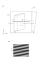
- FIG. 1 is a diagram illustrating a configuration of a collimation evaluation apparatus 100 of a comparative example.
- FIG. 2 is a diagram for explaining interference fringes formed on the screen 30 of the collimation evaluation apparatus 100 of the comparative examples (a) to (c).
- FIG. 3 is a diagram illustrating a configuration of the collimation evaluation apparatus 1 according to the first embodiment.
- FIG. 4 is a diagram illustrating a configuration of the collimation evaluation apparatus 2 according to the second embodiment.
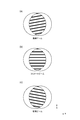
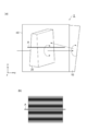
- FIG. 5 is a photograph of interference fringes observed on the screen 30 of the collimation evaluation apparatus 2 of the second embodiment (a) to (c).
- 6A to 6C are photographs of interference fringes observed on the screen 30 of the collimation evaluation apparatus 2 of the second embodiment.
- FIG. 1 is a diagram illustrating a configuration of a collimation evaluation apparatus 100 of a comparative example.
- FIG. 2 is a diagram for explaining interference fringes formed on the screen 30 of the collimation evaluation apparatus 100 of the comparative examples (
- FIGS. 7 is a diagram illustrating a configuration of the collimation evaluation apparatus 3 according to the third embodiment.
- FIG. 8 is a diagram illustrating a configuration of the collimation evaluation apparatus 4 according to the fourth embodiment.
- FIGS. 9A and 9B are diagrams showing the configuration of the collimation evaluation apparatus 5 according to the fifth embodiment.
- FIGS. 10A and 10B are diagrams for explaining an example of the operation of the collimation evaluation apparatus 5 according to the fifth embodiment.
- FIGS. 11A and 11B are diagrams illustrating an example of the operation of the collimation evaluation apparatus 5 according to the fifth embodiment.
- FIGS. 12A and 12B are diagrams for explaining another example of the operation of the collimation evaluation apparatus 5 according to the fifth embodiment.
- FIGS. 13A and 13B are diagrams for explaining another example of the operation of the collimation evaluation apparatus 5 according to the fifth embodiment.
- FIGS. 14A to 14C are photographs of interference fringes observed on the screen 30 of the collimation evaluation apparatus 5 according to the fifth embodiment.
- FIG. 15 is a diagram illustrating a configuration of a first modification of the collimation evaluation apparatus according to the first embodiment.
- FIG. 16 is a diagram illustrating a configuration of a second modification of the collimation evaluation apparatus according to the first embodiment.
- FIG. 17 is a diagram illustrating a configuration of a third modification of the collimation evaluation apparatus according to the first embodiment.
- FIG. 18 is a diagram illustrating a configuration of a fourth modification of the collimation evaluation apparatus of the first embodiment.
- FIG. 1 is a diagram illustrating a configuration of a collimation evaluation apparatus 100 of a comparative example.
- the collimation evaluation apparatus 100 of the comparative example includes a reflecting member 20, a screen 30, and a housing 40.
- the reflecting member 20 and the screen 30 are fixed to the housing 40. It is assumed that the direction in which the collimation evaluation target light L 0 is incident on the collimation evaluation apparatus 100 is parallel to the x-axis.
- the reflecting member 20 is a shear plate made of a transparent flat plate having a first reflecting surface 21 and a second reflecting surface 22 facing each other.
- the material of the transparent flat plate is, for example, BK7 or synthetic quartz.
- the reflecting member 20 is disposed so as to reflect the light L 0 incident parallel to the x axis and emit the reflected light parallel to the z axis.
- the flatness of the first reflecting surface 21 and the second reflecting surface 22 is about a fraction of the wavelength of the evaluation target light.
- the first reflecting surface 21 and the second reflecting surface 22 are not parallel to each other, and the distance between the reflecting surfaces changes along the direction parallel to the y-axis, and is about several seconds to several tens of seconds. (Wedge angle).
- the screen 30 is a ground glass plate arranged so as to be parallel to both the x-axis and the y-axis. Reflected light components L 1 and L 2 reflected by the first reflecting surface 21 and the second reflecting surface 22 of the reflecting member 20 are incident on the screen 30. Interference fringes are formed on the screen 30 by these two light components L 1 and L 2 , and the interference fringes can be observed.
- the evaluation target light L 0 is incident parallel to the reflecting member 20 to the x-axis.
- a part of the incident light L 0 is reflected by the first reflecting surface 21, and the reflected light L 1 enters the screen 30 in parallel with the z axis.
- the light transmitted through the first reflecting surface 21 is reflected by the second reflecting surface 22, and the reflected light L 2 enters the screen 30 parallel to the z axis.
- the reflected light component L 1 and the reflected light component L 2 incident on the screen 30 are shifted from each other in the direction parallel to the x-axis by an interval corresponding to the thickness of the reflecting member 20, and the thickness of the reflecting member 20 is increased.
- a corresponding optical path length difference is generated.
- FIG. 2 is a diagram illustrating interference fringes formed on the screen 30 of the collimation evaluation apparatus 100 of the comparative example.
- the interference fringes formed on the screen 30 are caused by the components caused by the first reflecting surface 21 and the second reflecting surface 22 of the reflecting member 20 being non-parallel to each other and the non-parallel nature of the incident light L 0.
- the interference fringes formed on the screen 30 include only components resulting from the first reflecting surface 21 and the second reflecting surface 22 being non-parallel to each other. Since the component due to the non-parallel property of the light L 0 is not included, it is parallel to the x-axis as shown in FIG.
- the interference fringes formed on the screen 30 are added to the components caused by the first reflecting surface 21 and the second reflecting surface 22 being non-parallel to each other.
- it since it also includes a component due to non-parallelism of the incident light L 0 , it is inclined with respect to the x-axis as shown in FIGS.
- the direction of inclination from one another The reverse is true.
- the collimation evaluation apparatus 100 of the comparative example in order to detect with high sensitivity the change in the direction of the interference fringes with respect to the reference line on the screen 30, it is desirable to increase the thickness of the reflective member 20 that is a shear plate. .
- the thickness of the reflective member 20 the optical path length difference between the reflected light L 1 that reaches the screen 30 and the reflected light L 2 is increased.
- it is able to observe interference fringes on the screen 30 is when the optical path length difference from the coherence length of the evaluation object light L 0 is short.
- the thickness of the reflecting member 20 is increased to improve the sensitivity, the optical path length difference increases, and it becomes impossible to perform collimation evaluation of light having a coherence distance shorter than the optical path length difference.
- the collimation evaluation apparatus 100 of the comparative example it is difficult to evaluate light collimation with a short coherence distance with high sensitivity.
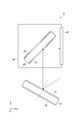
- FIG. 3 is a diagram illustrating a configuration of the collimation evaluation apparatus 1 according to the first embodiment.
- the collimation evaluation apparatus 1 according to the first embodiment includes a first reflecting member 10, a second reflecting member 20, a screen 30, and a housing 40.
- the first reflecting member 10, the second reflecting member 20, and the screen 30 are fixed to the housing 40. It is assumed that the direction in which the collimation evaluation target light L 0 is incident on the collimation evaluation apparatus 1 is parallel to the x-axis.
- the first reflecting member 10 is a transparent flat plate having a first reflecting surface 11 that reflects part of incident light and a second reflecting surface 12 that reflects light that has passed through the first reflecting surface 11 out of the light. It is.
- the second reflecting member 20 is a transparent flat plate having a first reflecting surface 21 that reflects a part of incident light and a second reflecting surface 22 that reflects light transmitted through the first reflecting surface 21 out of the light. It is.
- the material of these transparent flat plates is, for example, BK7 or synthetic quartz.
- the first reflecting member 10 When light that is incident in parallel to the x-axis and passes through the second reflecting member 20 is incident, the first reflecting member 10 reflects a part of the light on the first reflecting surface 11, and first reflection of the light is performed. The light transmitted through the surface 11 is reflected by the second reflecting surface 12 so that these reflected light components are emitted in the opposite direction.
- the second reflective member 20 When the light emitted from the first reflective member 10 is incident, the second reflective member 20 reflects a part of the light on the first reflective surface 21 and transmits the light transmitted through the first reflective surface 21 out of the light.
- the two reflection surfaces 22 reflect the reflected light components so that these reflected light components are emitted in parallel to the z-axis.
- each of the reflection surfaces 11, 12, 21, and 22 is about a fraction of the wavelength of the evaluation target light.
- the 1st reflective surface 11 and the 2nd reflective surface 12 are mutually parallel.
- the first reflecting surface 21 and the second reflecting surface 22 are not parallel to each other, and the distance between the reflecting surfaces is changed along the direction parallel to the y-axis.
- This is a shear plate whose reflecting surface forms an angle (wedge angle) of several seconds to several tens of seconds.
- the screen 30 is a ground glass plate arranged so as to be parallel to both the x-axis and the y-axis.
- the light reflected by the first reflecting surface 11 of the first reflecting member 10 and the first reflecting surface 21 of the second reflecting member 20 is denoted as L 11 .
- the light reflected by the second reflecting surface 22 of the first reflecting surface 11 and the second reflecting member 20 of the first reflecting member 10 is represented as L 12.
- the light reflected by the second reflecting surface 12 of the first reflecting member 10 and the first reflecting surface 21 of the second reflecting member 20 is denoted as L 21 .
- representative of the light reflected by the second reflecting surface 22 of the second reflecting surface 12 and the second reflecting member 20 of the first reflecting member 10 and L 22 are incident on the screen 30.
- interference fringes are formed by interference between those reflected light components L 11 , L 12 , L 21 , and L 22 having optical path length differences smaller than the coherence distance. Observable.
- the screen 30 is an observation unit that makes interference fringes observable.
- the direction of interference fringes caused by the first reflecting surface 21 and the second reflecting surface 22 of the second reflecting member 20 being non-parallel to each other and the direction of interference fringes caused by non-parallelism of incident light are: They are different from each other.
- the magnitude relationship between the optical path lengths of the reflected light components L 11 , L 12 , L 21 , and L 22 is as follows.
- the optical path lengths of these reflected light components differ depending on whether or not the light reciprocates between the first reflecting surface 11 and the second reflecting surface 12 of the first reflecting member 10, and the second reflecting member 20 has the first path length. It also differs depending on whether or not light reciprocates between the first reflecting surface 21 and the second reflecting surface 22. Accordingly, the optical path length of the reflected light component L 11 is short and the optical path length of the reflected light component L 22 is longer than the optical path lengths of the reflected light components L 12 and L 21 .
- the optical path length of each reflected light component L 12, L 21 can be comparable, reflected light component L 12, L 21 Can be made smaller than the coherence distance. That is, the light L 12 reflected by the first reflecting surface 11 of the first reflecting member 10 and the second reflecting surface 22 of the second reflecting member 20, and the second reflecting surface 12 and the second reflecting member 20 of the first reflecting member 10. Interference fringes can be formed on the screen 30 by the light L 21 reflected by the first reflecting surface 21.
- a reference line is drawn on the screen 30.
- the interference fringes are parallel to the reference line, it can be determined that the incident light is collimated light, and the incident light is diverged by the inclination of the interference fringes with respect to the reference line. Or it can determine with it being convergent light.
- the first reflection member 10 as described above using a second reflecting member 20 and the screen 30, both lights in screen 30 on which the reflected light component L 12 and the reflected light component L 21 is incident
- the interference fringes formed by the components are observed, and the collimation of the incident light is evaluated based on the observed direction of the interference fringes.
- the reflected light components L 12 , L 12 even when the thickness of the second reflecting member 20 is large in order to improve sensitivity, and even when the coherence distance of the light to be collimated is short. Since the optical path length difference of L 21 can be made smaller than the coherence distance, the collimation of the light can be evaluated with high sensitivity.
- the collimation evaluation apparatus 1 of the present embodiment has a configuration equivalent to that of the collimation evaluation apparatus 100 of the comparative example (that is, a configuration including the second reflecting member 20, the screen 30, and the housing 40). This corresponds to a case in which the incident direction of the light to be evaluated is reversed after adding one reflecting member 10.
- the first reflective member 10 for correcting the optical path length difference is attached to the commercially available collimation evaluation apparatus, thereby the present embodiment.
- the collimation evaluation apparatus 1 can be configured.
- a mounting method a method of attaching the first reflecting member 10 to a case of a commercially available collimation evaluation apparatus with an adhesive or an adhesive tape, and a method of attaching the first reflecting member to a case of a commercially available collimation evaluation apparatus using a holder having an adjustment mechanism.
- FIG. 4 is a diagram illustrating a configuration of the collimation evaluation apparatus 2 according to the second embodiment. Compared with the configuration of the collimation evaluation apparatus 1 of the first embodiment shown in FIG. 3, the collimation evaluation apparatus 2 of the second embodiment shown in FIG. 4 is different in the configuration of the first reflecting member 10.
- the first reflecting member 10 in the second embodiment includes a first flat plate 13 having a first reflecting surface 11 and a second flat plate 14 having a second reflecting surface 12 arranged in parallel to the first flat plate 13.
- the first reflecting surface 11 of the first flat plate 13 and the second reflecting surface 12 of the second flat plate 14 are opposed to each other and are parallel to each other. It is preferable that a reflection reducing film is formed on the surface of the first flat plate 13 opposite to the first reflecting surface 11. Further, it is preferable that a reflection reducing film is also formed on the surface of the second flat plate 14 opposite to the second reflecting surface 12.
- the second embodiment also operates in the same manner as the first embodiment and has the same effects.
- the interval between the first flat plate 13 and the second flat plate 14 is variable, that is, the interval between the first reflecting surface 11 and the second reflecting surface 12 is variable. It is. By doing so, the optical path length difference between the reflected light components L 12 and L 21 incident on the screen 30 can be adjusted, and the optical path length difference can be set according to the coherence distance of light.
- a moving mechanism In order to make the distance between the first flat plate 13 and the second flat plate 14 variable, a moving mechanism is provided that moves either or both of the first flat plate 13 and the second flat plate 14 in a direction parallel to the x-axis. Just do it.
- a stage having a high positional accuracy or an annular shim is preferably used.
- the collimation evaluation target light is laser light having a wavelength of 1080 nm and a coherence distance of 0.6 mm, which is emitted from the end face of the optical fiber laser light source, and is incident on the collimation evaluation apparatus 2 through the lens.
- the distance between the first flat plate 13 and the second flat plate 14 (that is, the distance between the first reflecting surface 11 and the second reflecting surface 12) is different by 0.20 mm in the range of 2.95 mm to 3.95 mm.
- the interference fringes formed on the screen 30 at each interval were photographed.
- FIG. 5A is a photograph of interference fringes when the spacing is 2.95 mm
- FIG. 5B is a photograph of interference fringes when the spacing is 3.15 mm
- FIG. 5C is 3.35 mm spacing. It is a photograph of the interference fringes in the case of.
- FIG. 6A is a photograph of interference fringes when the spacing is 3.55 mm
- FIG. 6B is a photograph of interference fringes when the spacing is 3.75 mm
- FIG. 6C is a spacing of 3.95 mm. It is a photograph of the interference fringes in the case of.
- the distance between the first flat plate 13 and the second flat plate 14 of the first reflecting member 10 is set according to the thickness of the second reflecting member 20 so that the length difference cancels.
- FIG. 7 is a diagram illustrating a configuration of the collimation evaluation apparatus 3 according to the third embodiment.
- the collimation evaluation apparatus 3 according to the third embodiment includes a first reflecting member 10, a second reflecting member 20, a screen 30 and a housing 40.
- the first reflecting member 10, the second reflecting member 20, and the screen 30 are fixed to the housing 40. It is assumed that the direction in which the collimation evaluation target light enters the collimation evaluation apparatus 3 is parallel to the z axis.
- the first reflecting member 10, the second reflecting member 20, and the screen 30 in the third embodiment are the same as those in the first embodiment, but are different from the first embodiment in arrangement.
- the first reflecting member 10 When light is incident in parallel to the z axis, the first reflecting member 10 reflects a part of the light on the first reflecting surface 11, and the light that has passed through the first reflecting surface 11 out of the light is reflected on the second reflecting surface. 12 so that these reflected light components are emitted in a direction parallel to the x-axis.
- the second reflective member 20 reflects a part of the light on the first reflective surface 21 and transmits the light transmitted through the first reflective surface 21 out of the light.
- the two reflection surfaces 22 reflect the reflected light components so that these reflected light components are emitted in parallel to the z-axis.
- the screen 30 is a ground glass plate arranged so as to be parallel to both the x-axis and the y-axis.
- the reflected light components L 11 , L 12 , L 21 and L 22 are incident on the screen 30.
- the optical path lengths of the reflected light components L 12 and L 21 can be made similar, and the reflected light component The optical path length difference between L 12 and L 21 can be made smaller than the coherent distance. That is, the light L 12 reflected by the first reflecting surface 11 of the first reflecting member 10 and the second reflecting surface 22 of the second reflecting member 20, and the second reflecting surface 12 and the second reflecting member 20 of the first reflecting member 10. Interference fringes can be formed on the screen 30 by the light L 21 reflected by the first reflecting surface 21.
- the reflected light component L 12 even when the thickness of the second reflecting member 20 is large in order to improve sensitivity, and even when the coherence distance of the light to be collimated is short. since the optical path length difference L 21 can be made smaller than the coherence length, it is possible to evaluate the optical collimation sensitivity.
- the evaluation target light is incident on the first reflecting member 10 after passing through the second reflecting member 20, and thus loses when passing through the second reflecting member 20.
- the evaluation target light can be directly incident on the first reflecting member 10 without being transmitted through the second reflecting member 20. There is no loss.
- FIG. 8 is a diagram illustrating a configuration of the collimation evaluation apparatus 4 according to the fourth embodiment. Compared with the configuration of the collimation evaluation apparatus 3 of the third embodiment shown in FIG. 7, the collimation evaluation apparatus 4 of the fourth embodiment shown in FIG. 8 is different in the arrangement of the first reflecting member 10.
- the first reflecting surface 11 and the second reflecting surface 12 are arranged so as to be inclined by 45 degrees with respect to both the x axis and the z axis, and the incident angle of light and Both reflection angles were 45 degrees.
- the first reflecting surface 11 and the second reflecting surface 12 are arranged so as to be rotatable around an axis parallel to the y axis. The angle and the emission angle are variable.
- the direction of the light which injects into the 1st reflective member 10 is set so that the light reflected by the 1st reflective member 10 may radiate
- the optical path length difference between the first reflected light component generated upon reflection at the reflecting member 10 L 12, L 21, of the second reflected light component generated upon reflection at the reflecting member 20 L 12, L 21 The orientation of the first reflecting member 10 is adjusted according to the thickness of the second reflecting member 20 so that the optical path length difference cancels out.
- the azimuth of the first reflecting member 10 it is possible to adjust the optical path length difference between the reflected light components L 12 and L 21 that are generated when the first reflecting member 10 is reflected.
- the orientation of the first reflecting member 10 is changed.
- the optical path length difference between the reflected light components L 12 and L 21 can be made smaller than the coherence distance, so that the collimation of the light can be evaluated with high sensitivity.
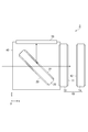
- FIG. 9 is a diagram illustrating a configuration of the collimation evaluation apparatus 5 according to the fifth embodiment.
- FIG. 9A is a top view seen in a direction parallel to the z-axis (a direction perpendicular to the screen 30).
- FIG. 9B is a side view seen in a direction parallel to the y-axis. In FIG. 9A, illustration of the screen 30 is omitted.
- the first reflecting surface 11 and the second reflecting surface 12 of the first reflecting member 10 are parallel to each other.
- the 1st reflective surface 11 and the 2nd reflective surface 12 of the 1st reflective member 10 are mutually non-parallel, and are the distance between both reflective surfaces along one direction. Has changed, forming an angle (wedge angle) of several seconds to several tens of seconds. That is, in the fifth embodiment, both the first reflecting member 10 and the second reflecting member 20 are shear plates.
- the first reflecting member 10 is disposed so as to be rotatable around an axis perpendicular to the x axis.
- FIGS. 10B and 11B are diagrams illustrating an example of the operation of the collimation evaluation apparatus 5 according to the fifth embodiment.
- FIG. 10A and FIG. 11A is a top view of the collimation evaluation apparatus 5 of the fifth embodiment.
- FIGS. 10B and 11B are diagrams showing interference fringes observed in the case of FIG. 10A corresponding to FIG. In these figures, the screen 30 is not shown.
- the distance between the first reflecting surface 21 and the second reflecting surface 22 of the second reflecting member 20 becomes narrower as it proceeds in the + y direction.
- the distance between the first reflecting surface 11 and the second reflecting surface 12 is also narrowed in the first reflecting member 10 as it proceeds in the + y direction. That is, the wedge directions of the first reflecting member 10 and the second reflecting member 20 are the same. In this case, as shown in FIG. 10B, the interval between the interference fringes becomes wide.
- the distance between the first reflecting surface 11 and the second reflecting surface 12 is increased as it proceeds in the + y direction. That is, the wedge directions of the first reflecting member 10 and the second reflecting member 20 are opposite to each other. In this case, as shown in FIG. 11B, the interval between the interference fringes becomes narrow.
- the interval between the interference fringes depends on the sum of the wedge angles of the first reflecting member 10 and the second reflecting member 20, and also depends on the wavelength of light to be collimated.
- the wedge angle of the first reflection member 10 and theta 1, the wedge angle of the second reflecting member 20 and theta 2, eg, ⁇ 1 ⁇ 2/3.
- the entire wedge angle when the first reflection member 10 and the second reflecting member 20 each wedge directions are opposite to each other becomes 2 [Theta] 2/3.
- Overall wedge angle 4? 2/3 next to the case where the first reflecting member 10 and the second reflecting member 20 each wedge directions are the same to each other, and 2 times the overall wedge angle when the wedge direction are opposite to each other Become.
- FIG. 12 and 13 are diagrams illustrating another example of the operation of the collimation evaluation apparatus 5 according to the fifth embodiment.
- FIG. 12A and FIG. 13A is a top view of the collimation evaluation apparatus 5 of the fifth embodiment.
- FIG. 12B and FIG. 13B is a diagram illustrating interference fringes observed in the case of FIG. In these drawings, the screen 30 is not shown, but a reference line A drawn on the screen 30 is shown.
- the distance between the first reflecting surface 21 and the second reflecting surface 22 of the second reflecting member 20 becomes narrower as it proceeds in the substantially + y direction, but the accuracy of attachment to the housing 40 is insufficient.
- the wedge direction is somewhat inclined from the y direction.
- the distance between the first reflecting surface 11 and the second reflecting surface 12 is increased as it advances in the + y direction, and the wedge direction is accurately set in the y direction. It has become. In this case, even if the evaluation target light is good collimated light, the interference fringes are inclined with respect to the reference line A as shown in FIG.
- the first reflecting member 10 has a gap between the first reflecting surface 21 and the second reflecting surface 22 that increases in the substantially + y direction, but the wedge direction is the y direction. It is somewhat inclined from.
- the inclination of the first reflecting member 10 in the wedge direction is set so as to cancel the inclination of the second reflecting member 20 in the wedge direction.
- the interference fringes are parallel to the reference line A as shown in FIG.
- the wedge direction of the second reflecting member 20 is slightly inclined from the y direction due to insufficient accuracy of the attachment of the second reflecting member 20 to the housing 40.
- the collimation of the evaluation target light can be accurately evaluated.
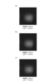
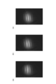
- FIG. 14 is a photograph of interference fringes observed on the screen 30 of the collimation evaluation apparatus 5 of the fifth embodiment.
- the collimation evaluation target light is laser light having a wavelength of 1080 nm and a coherence distance of 0.6 mm, which is emitted from the end face of the optical fiber laser light source, and is incident on the collimation evaluation apparatus 5 through the lens.
- the wedge direction of the first reflecting member 10 was varied by 90 degrees, and the interference fringes formed on the screen 30 in each wedge direction were photographed.
- FIG. 14B shows that the wedge direction of the first reflecting member 10 is rotated by 90 degrees.
- FIG. 14C shows the interference fringes when the wedge direction of the first reflecting member 10 is rotated by 180 degrees.
- FIGS. 15 to 18 are diagrams showing a configuration of a modification of the collimation evaluation apparatus 1 of the first embodiment. In these modified examples, another configuration is adopted as an observation unit for making interference fringes observable.
- the collimation evaluation apparatus 1A of the first modified example shown in FIG. 15 uses the reflective screen 31 as an observation unit, and observes the interference fringes by the light reflected and diffused by the screen 30. This configuration is suitable from the viewpoint of observer safety when observing interference fringes of high-intensity light.
- the collimation evaluation apparatus 1B of the second modification shown in FIG. 16 observes the interference fringes by displaying the interference fringes imaged by the camera 32 on the display device using the camera 32 as an observation unit.
- interference fringes can be observed even with light in a wavelength region other than visible light (ultraviolet region, infrared region, etc.).
- the collimation evaluation apparatus 1C of the third modification shown in FIG. 17 uses the lens 33 and the camera 32 as an observation unit, images an interference fringe enlarged or reduced by the lens 33 with the camera 32, and picks up the captured interference fringe. Is displayed on the display device to observe interference fringes. In the case of this configuration, interference fringes can be observed even with light in a wavelength region other than visible light, and interference fringes can be observed in a desired field of view by changing the magnification.
- the collimation evaluation apparatus 1D of the fourth modified example shown in FIG. 18 uses a transmissive screen 30, a lens 33, and a camera 32 as an observation unit, and enlarges or reduces interference fringes on the screen 30 with the lens 33.
- the interference fringes are observed by picking up an image by 32 and displaying the picked-up interference fringes on the display device. Also in this configuration, interference fringes can be observed even with light in a wavelength region other than visible light, and interference fringes with a desired interval can be observed by changing the magnification. Further, the inclination of the interference fringes with respect to the reference line drawn on the screen 30 can be confirmed.
- the collimation evaluation apparatuses 1B and 1C that do not use the screen cannot use the reference line on the screen, but can use the electronic line of the camera 32 as the reference line.
- collimation evaluation apparatuses 1A to 1D are modifications of the collimation evaluation apparatus 1 of the first embodiment, but similar modifications are possible in the collimation evaluation apparatuses 2 to 5 of other embodiments.
- the first reflecting surface 11 and the second reflecting surface 12 of the first reflecting member 10 are parallel to each other, and the first reflecting surface 21 of the second reflecting member 20 and The second reflecting surface 22 is assumed to be non-parallel to each other.
- the first reflecting surface 11 and the second reflecting surface 12 of the first reflecting member 10 are non-parallel to each other, and the first reflecting surface 21 and the second reflecting surface 22 of the second reflecting member 20 are. And may be parallel to each other. Further, in both the first reflecting member 10 and the second reflecting member 20, the first reflecting surface and the second reflecting surface may be non-parallel to each other.
- the direction of the interference fringes caused by the first reflecting surface and the second reflecting surface being non-parallel to each other and / or the first reflecting member 10 and / or the second reflecting member 20
- the first reflecting member 10 and the second reflecting member 20 are arranged so that the directions of the interference fringes resulting from the non-parallelism of light are different from each other.
- the light L 12 reflected by the first reflecting surface 11 of the first reflecting member 10 and the second reflecting surface 22 of the second reflecting member 20 and the second reflecting surface 12 and the second reflecting member 20 of the first reflecting member 10 are reflected.
- the interference fringes formed by the light L 21 reflected by the first reflecting surface 21 are observed, and the collimation of the incident light can be evaluated based on the observed orientation of the interference fringes.
- the first reflecting member 10 is constituted by two flat plates, but the second reflecting member 20 may also be constituted by two flat plates.
- the first reflecting member 10 or the second reflecting member 20 is composed of two flat plates, by adjusting the spacing between the two flat plates, adjusting the optical path length difference between the reflected light component L 12, L 21 Can do.
- the wedge angle and the wedge direction of the reflecting member can be adjusted by adjusting the inclination of both or one of the two flat plates.
- a first reflection surface that reflects a part of incident light and a second reflection surface that reflects light that has passed through the first reflection surface of the incident light.
- a first reflecting member having (2) a first reflecting surface that reflects a part of the light emitted from the first reflecting member, and a second reflecting surface that reflects the light transmitted through the first reflecting surface of the light. And (3) a light component reflected by the first reflecting surface of the first reflecting member and the second reflecting surface of the second reflecting member, and the second reflecting surface of the first reflecting member.
- the collimation of incident light is evaluated based on the direction of interference fringes formed by the light component reflected by the first reflecting surface of the second reflecting member.
- a first reflecting member having (2) a first reflecting surface that reflects a part of the light emitted from the first reflecting member, and a second reflecting surface that reflects the light transmitted through the first reflecting surface of the light. And (a) the light component reflected by the first reflecting surface of the first reflecting member and the second reflecting surface of the second reflecting member, and the second reflecting surface of the first reflecting member.
- the interference fringes formed by the light component reflected by the first reflecting surface of the second reflecting member are observed, and (b) the collimation of the incident light is evaluated based on the observed orientation of the interference fringes.
- the first reflecting member and the second reflecting member are not parallel to each other in either or either of the first reflecting member and the second reflecting member.
- a configuration in which the orientation of interference fringes resulting from non-parallelism between the first reflecting surface and the second reflecting surface in both or any one of them and the orientation of interference fringes resulting from non-parallelism of incident light are different from each other It is preferable that
- the first reflecting member and the second reflecting member are not parallel to each other in either or either of the first reflecting member and the second reflecting member.
- the direction of interference fringes resulting from non-parallelism between the first reflecting surface and the second reflecting surface in both or either of the reflecting members and the direction of interference fringes resulting from non-parallelism of incident light It is preferable that the first reflecting member and the second reflecting member are arranged so as to be different from each other.
- the first reflection member and / or the second reflection member each include a flat plate having two surfaces facing each other as the first reflection surface and the second reflection surface. It is also good.
- the first reflection member and / or the second reflection member are arranged in parallel with the first flat plate having the first reflection surface and the first flat plate. It is good also as a structure containing the 2nd flat plate which has 2 reflective surfaces.
- the interval between the first flat plate and the second flat plate (that is, the interval between the first reflecting surface and the second reflecting surface) is variable. By appropriately setting this interval, the optical path length difference between the two reflected light components L 12 and L 21 can be adjusted, and the optical path length difference can be made smaller than the coherent distance. It can be evaluated with high sensitivity.
- the first reflection member and the second reflection member are nonparallel to each other in both the first reflection member and the second reflection member. Both or either of them may be rotatable around an axis substantially perpendicular to the first reflecting surface or the second reflecting surface. In this case, the interval between the interference fringes can be adjusted by adjusting the rotation position of the first reflecting member or the second reflecting member. Further, even if the accuracy of mounting one of the first reflecting member and the second reflecting member is insufficient, the collimation of incident light can be accurately evaluated by adjusting the rotational position of the other reflecting member. Can do.
- the signal intensity is reduced to the four surfaces of the reflecting surfaces 21 and 22, or the reflecting surfaces 11 and 12, or the reflecting surfaces 21, 22, 11, and 12.
- a coating for reducing the reflectance may be provided.
- the reflectances of the reflecting surfaces 21 and 22 and the reflectances of the reflecting surfaces 11 and 12 are approximately the same.
- a reflectance of about 1% can be realized on the glass surface and the glass back surface by laminating one layer each of aluminum oxide Al 2 O 3 and magnesium fluoride MgF 2 .
- the present invention can be used as an apparatus and a method that can evaluate collimation of light with high sensitivity even when the coherence distance of light subjected to collimation evaluation is short.
Landscapes
- Physics & Mathematics (AREA)
- Spectroscopy & Molecular Physics (AREA)
- General Physics & Mathematics (AREA)
- Chemical & Material Sciences (AREA)
- Analytical Chemistry (AREA)
- Instruments For Measurement Of Length By Optical Means (AREA)
- Testing Of Optical Devices Or Fibers (AREA)
- Length Measuring Devices By Optical Means (AREA)
Abstract
Lorsque la lumière ayant traversé un second élément réfléchissant (20) est incidente sur un premier élément réfléchissant (10), une partie de ladite lumière est réfléchie par une première surface réfléchissante (11), la partie de ladite lumière ayant traversé la première surface réfléchissante (11) est réfléchie par une seconde surface réfléchissante (12) et ces composants de lumière réfléchie sont émis dans des directions opposées. Lorsque la lumière émise par le premier élément réfléchissant (10) est incidente sur le second élément réfléchissant (20), une partie de ladite lumière est réfléchie par une première surface réfléchissante (21), la partie de ladite lumière ayant traversé la première surface réfléchissante (21) est réfléchie par une seconde surface réfléchissante (22) et ces composants de lumière réfléchie sont émis. La lumière L12 réfléchie par la première surface réfléchissante (11) du premier élément réfléchissant (10) et la seconde surface réfléchissante (22) du second élément réfléchissant (20), et la lumière L21 réfléchie par la seconde surface réfléchissante (12) du premier élément réfléchissant (10) et la première surface réfléchissante (21) du second élément réfléchissant (20) forment un motif d'interférence sur un écran (30). L'invention concerne un dispositif et un procédé permettant d'évaluer la collimation de lumière avec une sensibilité élevée, même si la longueur de cohérence de ladite lumière est courte.
Priority Applications (3)
| Application Number | Priority Date | Filing Date | Title |
|---|---|---|---|
| US15/329,377 US10260987B2 (en) | 2014-07-30 | 2015-07-29 | Collimation evaluation device and collimation evaluation method |
| CN201580041372.1A CN106662486B (zh) | 2014-07-30 | 2015-07-29 | 准直评价装置和准直评价方法 |
| EP15827109.8A EP3176552B1 (fr) | 2014-07-30 | 2015-07-29 | Dispositif et procede d'evaluation de collimation |
Applications Claiming Priority (2)
| Application Number | Priority Date | Filing Date | Title |
|---|---|---|---|
| JP2014154779A JP6483973B2 (ja) | 2014-07-30 | 2014-07-30 | コリメーション評価装置およびコリメーション評価方法 |
| JP2014-154779 | 2014-07-30 |
Publications (1)
| Publication Number | Publication Date |
|---|---|
| WO2016017706A1 true WO2016017706A1 (fr) | 2016-02-04 |
Family
ID=55217604
Family Applications (1)
| Application Number | Title | Priority Date | Filing Date |
|---|---|---|---|
| PCT/JP2015/071528 Ceased WO2016017706A1 (fr) | 2014-07-30 | 2015-07-29 | Dispositif et procede d'evaluation de collimation |
Country Status (5)
| Country | Link |
|---|---|
| US (1) | US10260987B2 (fr) |
| EP (1) | EP3176552B1 (fr) |
| JP (1) | JP6483973B2 (fr) |
| CN (1) | CN106662486B (fr) |
| WO (1) | WO2016017706A1 (fr) |
Cited By (1)
| Publication number | Priority date | Publication date | Assignee | Title |
|---|---|---|---|---|
| US10309836B2 (en) | 2015-08-25 | 2019-06-04 | Hamamatsu Photonics K.K. | Collimation evaluation device and collimation evaluation method |
Families Citing this family (2)
| Publication number | Priority date | Publication date | Assignee | Title |
|---|---|---|---|---|
| KR20190060022A (ko) * | 2017-11-23 | 2019-06-03 | 삼성디스플레이 주식회사 | 레이저용 시어링 간섭계 |
| JP7564719B2 (ja) * | 2021-01-28 | 2024-10-09 | 浜松ホトニクス株式会社 | レーザ加工装置及びレーザ加工方法 |
Citations (2)
| Publication number | Priority date | Publication date | Assignee | Title |
|---|---|---|---|---|
| US20040051877A1 (en) * | 2002-09-18 | 2004-03-18 | Erwin J. Kevin | Small-beam lateral-shear interferometer |
| JP2009103592A (ja) * | 2007-10-24 | 2009-05-14 | Sigma Koki Kk | コリメーション検査装置 |
Family Cites Families (5)
| Publication number | Priority date | Publication date | Assignee | Title |
|---|---|---|---|---|
| US5270792A (en) * | 1990-03-28 | 1993-12-14 | Blue Sky Research, Inc. | Dynamic lateral shearing interferometer |
| JP2001336914A (ja) | 2000-05-26 | 2001-12-07 | Sigma Koki Kk | コリメーション検査装置 |
| JP4114847B2 (ja) | 2001-03-21 | 2008-07-09 | 株式会社リコー | コリメート評価装置 |
| CN100547366C (zh) | 2007-08-22 | 2009-10-07 | 中国科学院上海光学精密机械研究所 | 移相横向剪切干涉仪 |
| JP5660514B1 (ja) * | 2013-12-04 | 2015-01-28 | レーザーテック株式会社 | 位相シフト量測定装置及び測定方法 |
-
2014
- 2014-07-30 JP JP2014154779A patent/JP6483973B2/ja active Active
-
2015
- 2015-07-29 WO PCT/JP2015/071528 patent/WO2016017706A1/fr not_active Ceased
- 2015-07-29 US US15/329,377 patent/US10260987B2/en active Active
- 2015-07-29 CN CN201580041372.1A patent/CN106662486B/zh active Active
- 2015-07-29 EP EP15827109.8A patent/EP3176552B1/fr active Active
Patent Citations (2)
| Publication number | Priority date | Publication date | Assignee | Title |
|---|---|---|---|---|
| US20040051877A1 (en) * | 2002-09-18 | 2004-03-18 | Erwin J. Kevin | Small-beam lateral-shear interferometer |
| JP2009103592A (ja) * | 2007-10-24 | 2009-05-14 | Sigma Koki Kk | コリメーション検査装置 |
Non-Patent Citations (5)
| Title |
|---|
| LI G H ET AL.: "Improved wedge-plate shearing interferometric technique for a collimation test", APPLIED OPTICS, vol. 31, no. 22, pages 4363 - 4364, XP000292079 * |
| See also references of EP3176552A4 * |
| SRIRAM K V ET AL.: "Self-referencing collimation testing techniques", OPTICAL ENGINEERING, vol. 32, no. 1, January 1993 (1993-01-01), pages 94 - 100, XP000336032, DOI: doi:10.1117/12.60081 * |
| STAUB F ET AL.: "Collimation tester for ultrashort pulses and short coherence length lasers", OPTIK, vol. 117, no. 4, April 2006 (2006-04-01), pages 193 - 195, XP025192406, DOI: doi:10.1016/j.ijleo.2005.08.006 * |
| XU D Y ET AL.: "Rotatable single wedge plate shearing interference technique for collimation testing", OPTICAL ENGINEERING, vol. 30, no. 4, April 1991 (1991-04-01), pages 391 - 396, XP000202157 * |
Cited By (1)
| Publication number | Priority date | Publication date | Assignee | Title |
|---|---|---|---|---|
| US10309836B2 (en) | 2015-08-25 | 2019-06-04 | Hamamatsu Photonics K.K. | Collimation evaluation device and collimation evaluation method |
Also Published As
| Publication number | Publication date |
|---|---|
| CN106662486B (zh) | 2019-12-03 |
| US10260987B2 (en) | 2019-04-16 |
| US20170219458A1 (en) | 2017-08-03 |
| EP3176552A1 (fr) | 2017-06-07 |
| JP2016031333A (ja) | 2016-03-07 |
| JP6483973B2 (ja) | 2019-03-13 |
| EP3176552B1 (fr) | 2019-05-01 |
| CN106662486A (zh) | 2017-05-10 |
| EP3176552A4 (fr) | 2018-02-14 |
Similar Documents
| Publication | Publication Date | Title |
|---|---|---|
| JP7286765B2 (ja) | 共焦点光学分度器 | |
| CN114502912B (zh) | 混合式3d检验系统 | |
| US9774417B2 (en) | Polarization splitting multiplexing device, optical system, and display unit | |
| US8891090B2 (en) | Light-interference measuring apparatus | |
| US7471396B2 (en) | Dual polarization interferometers for measuring opposite sides of a workpiece | |
| JP2017032644A (ja) | 表示装置 | |
| CN101595737B (zh) | 光电子装置 | |
| EP2584305A1 (fr) | Elément optique et interféromètre | |
| JP6063166B2 (ja) | 干渉計方式により間隔測定するための機構 | |
| JP6483973B2 (ja) | コリメーション評価装置およびコリメーション評価方法 | |
| JP6285808B2 (ja) | 干渉計 | |
| CN106907987B (zh) | 一种干涉成像光学系统 | |
| CN106104948B (zh) | 半导体激光装置 | |
| JP6654830B2 (ja) | コリメーション評価装置およびコリメーション評価方法 | |
| CN111433650B (zh) | 单稳态或准单稳态激光测距仪的保护 | |
| JP4583611B2 (ja) | 斜入射干渉計装置 | |
| CN1499171A (zh) | 一种具有自动准直功能和距离测量功能的观测仪器 | |
| CN119123970B (zh) | 一种紧凑型四光束干涉仪、制造方法及测量方法 | |
| JP7843439B2 (ja) | 測定装置及び方法 | |
| JP2006349382A (ja) | 位相シフト干渉計 | |
| JP2009025181A (ja) | 厚み測定用光干渉測定装置 | |
| JP2000275031A (ja) | 角度または角変位測定に用いるコーナーキューブリフレクターを含む反射光学系 | |
| JP2013061536A (ja) | 光学装置 | |
| JP2006053049A (ja) | 干渉計 |
Legal Events
| Date | Code | Title | Description |
|---|---|---|---|
| 121 | Ep: the epo has been informed by wipo that ep was designated in this application |
Ref document number: 15827109 Country of ref document: EP Kind code of ref document: A1 |
|
| WWE | Wipo information: entry into national phase |
Ref document number: 15329377 Country of ref document: US |
|
| NENP | Non-entry into the national phase |
Ref country code: DE |
|
| REEP | Request for entry into the european phase |
Ref document number: 2015827109 Country of ref document: EP |
|
| WWE | Wipo information: entry into national phase |
Ref document number: 2015827109 Country of ref document: EP |