WO2016020171A1 - Belüftungsvorrichtung - Google Patents
Belüftungsvorrichtung Download PDFInfo
- Publication number
- WO2016020171A1 WO2016020171A1 PCT/EP2015/066421 EP2015066421W WO2016020171A1 WO 2016020171 A1 WO2016020171 A1 WO 2016020171A1 EP 2015066421 W EP2015066421 W EP 2015066421W WO 2016020171 A1 WO2016020171 A1 WO 2016020171A1
- Authority
- WO
- WIPO (PCT)
- Prior art keywords
- horizontal
- vertical
- lamella
- ventilation device
- pivot axis
- Prior art date
- Legal status (The legal status is an assumption and is not a legal conclusion. Google has not performed a legal analysis and makes no representation as to the accuracy of the status listed.)
- Ceased
Links
Images

Classifications
-
- F—MECHANICAL ENGINEERING; LIGHTING; HEATING; WEAPONS; BLASTING
- F24—HEATING; RANGES; VENTILATING
- F24F—AIR-CONDITIONING; AIR-HUMIDIFICATION; VENTILATION; USE OF AIR CURRENTS FOR SCREENING
- F24F13/00—Details common to, or for air-conditioning, air-humidification, ventilation or use of air currents for screening
- F24F13/08—Air-flow control members, e.g. louvres, grilles, flaps or guide plates
- F24F13/10—Air-flow control members, e.g. louvres, grilles, flaps or guide plates movable, e.g. dampers
- F24F13/14—Air-flow control members, e.g. louvres, grilles, flaps or guide plates movable, e.g. dampers built up of tilting members, e.g. louvre
- F24F13/15—Air-flow control members, e.g. louvres, grilles, flaps or guide plates movable, e.g. dampers built up of tilting members, e.g. louvre with parallel simultaneously tiltable lamellae
-
- B—PERFORMING OPERATIONS; TRANSPORTING
- B60—VEHICLES IN GENERAL
- B60H—ARRANGEMENTS OF HEATING, COOLING, VENTILATING OR OTHER AIR-TREATING DEVICES SPECIALLY ADAPTED FOR PASSENGER OR GOODS SPACES OF VEHICLES
- B60H1/00—Heating, cooling or ventilating devices
- B60H1/34—Nozzles; Air-diffusers
- B60H1/3414—Nozzles; Air-diffusers with means for adjusting the air stream direction
- B60H1/3421—Nozzles; Air-diffusers with means for adjusting the air stream direction using only pivoting shutters
-
- F—MECHANICAL ENGINEERING; LIGHTING; HEATING; WEAPONS; BLASTING
- F24—HEATING; RANGES; VENTILATING
- F24F—AIR-CONDITIONING; AIR-HUMIDIFICATION; VENTILATION; USE OF AIR CURRENTS FOR SCREENING
- F24F13/00—Details common to, or for air-conditioning, air-humidification, ventilation or use of air currents for screening
- F24F13/08—Air-flow control members, e.g. louvres, grilles, flaps or guide plates
- F24F13/10—Air-flow control members, e.g. louvres, grilles, flaps or guide plates movable, e.g. dampers
- F24F13/14—Air-flow control members, e.g. louvres, grilles, flaps or guide plates movable, e.g. dampers built up of tilting members, e.g. louvre
- F24F13/142—Air-flow control members, e.g. louvres, grilles, flaps or guide plates movable, e.g. dampers built up of tilting members, e.g. louvre using pivoting blades with intersecting axles
Definitions
- the invention relates to a ventilation device for controlling an outflow direction of an air flow.
- a ventilation device which is provided in particular for an instrument panel component of a motor vehicle for ventilation of an interior space.
- This ventilation device has an outer housing, in which a control flap is provided for volume change.
- an inner housing is provided which receives a plurality of spaced-apart horizontal slats fixedly disposed in the inner housing.
- This inner housing is pivotally mounted about a horizontal pivot axis in the outer housing.
- the inner housing receives a plurality of mutually spaced vertical slats, which are aligned perpendicular to the fixed horizontal slats.
- These vertical slats have slots, so that in these slots, the horizontal slats can be inserted and the horizontal and vertical slats lie in a common plane in the outflow.
- the vertical louvers are pivotally controllable about a vertical pivot axis.
- This arrangement has the disadvantage that, to change the flow direction deviating from the horizontal, the inner housing must be pivotally driven, this inner housing, for example, at the top in sections against an end panel of the ventilation device emerges and recedes below, whereby the visual impression is impaired.
- the horizontal slats are controlled independently of the vertical slats.
- a ventilation device with a multifunctional control knob through which the horizontal lamella, the vertical lamella and the closing flap are adjustable.
- the horizontal louvers are formed by a housing which can be pivoted up and down and behind it inside the housing of the ventilation device, the vertical louvers are arranged separately.
- a ventilation device in which the horizontal and vertical slats can be controlled by a single control element, wherein arranged in the interior of the housing, the vertical slats and separately to the visible side of the ventilation device pointing and separated from the vertical slats the horizontal slats are arranged.
- these ventilation devices allow the independent control of the vertical slats and the horizontal slats due to the spatially separated arrangement arranged one behind the other, but this is not a homogeneous optics of a Ausströmfeldes the ventilation device possible to the visible side.
- the invention is therefore based on the object to propose a ventilation device, which allows flexible adjustment in the outflow of the air flow and has a homogeneous attractive appearance of Ausströmfeldes.
- a ventilation device in which the horizontal lamella and vertical lamella are arranged crosswise nested, wherein the horizontal louvers and the vertical louvers are each mounted pivotably about the pivot axis in the housing.
- a preferred embodiment of the invention provides that the vertical louvers and the horizontal louvers are arranged freely at their intersection points, so that their setting in the desired orientation is easily adjustable.
- the crossing points can also form a bearing point, by which the vertical lamella about the vertical pivot axis and the horizontal lamella is pivotable about the horizontal pivot axis.
- These can also be made flexible, for example to compensate for tolerances. This has the advantage that is supported by the crosswise arrangement and nesting of the horizontal and vertical lamella each other in the crossing points through the bearing, so that a stable and consistent lattice structure is maintained. At the same time the mutual deflection can be secured to each other in a simple manner.
- the crossing point is formed by a groove-shaped depression in the horizontal or vertical lamella, in which a bearing journal of the horizontal or vertical lamella is received.
- This refinement has the advantage that the crossing point, in particular when it forms a bearing point, is virtually unnoticed by the visible side of the ventilation device and visually moves into the background, as a result of which the homogeneous appearance of the outflow field can be enhanced.
- a bearing can be formed without additional bearing elements.
- a further preferred embodiment of the ventilation device provides that the horizontal or vertical lamella identifies a V-shaped recess, which extends counter to the outflow from a crossing point of the horizontal and vertical lamella.
- This V-shaped recess allows, starting from the intersection of the horizontal and vertical lamella, each pivotal movement, so that the horizontal lamella about the horizontal pivot axis and the vertical lamella about the vertical pivot axis for driving the outflow direction is pivotable.
- the horizontal or vertical lamella pointing along its pivot axis and counter to the outflow pointing triangular or pennet-shaped vanes.
- These triangular or vane shaped guide surfaces result from the V-shaped recesses and allow the V-shaped recess to determine the pivotal range of the horizontal louver.
- the guide surfaces may also comprise, following a triangular or pennant-shaped guide surface, an enlarging guide surface which extends counter to the outflow direction.
- the vertical lamella can only partially reduce the width of the guide surface to form a pivoting range for the horizontal lamella.
- the horizontal and / or vertical lamella have along the pivot axis juxtaposed triangular guide surfaces, which are interconnected by axle sections.
- the horizontal or vertical lamella is integrally formed of plastic as a plastic injection molded part, so that both the guide surfaces and the bearing pin can be integrated with each other.
- the horizontal or vertical lamella preferably has, along the longitudinal axis and adjacent to the intersection points, a continuously formed guide surface which extends counter to the outflow direction.
- the longer lamella is formed by the two lamellae with the continuous guide surface.
- the pivot axis of the horizontal lamella and the pivot axis of the vertical lamella preferably intersect at the crossing points. As a result, the superposition of the horizontal and vertical lamellae in the structure is simplified.
- the pivot axis of the horizontal and vertical slats lie in a common plane. This arrangement allows for a flat housing, i. that starting from a cover plate or panel on the visible side of the ventilation device only a small space is required, which projects into the ventilation duct of the ventilation system.
- the horizontal louvers are preferably jointly controlled by a hinge assembly. This has the advantage that a coupling point for force application is sufficient to control all horizontal slats simultaneously.
- the vertical slats can be actuated, for example, via a common push rod, so that a movement of the push rod in the horizontal direction is sufficient to control a lateral outflow direction.
- a regulating device is provided according to a first embodiment, which in each case has an actuating element for the horizontal and vertical slats.
- the regulating device has a single control element, which controls the joint arrangement for controlling the horizontal slats and the push rod for controlling the vertical slats via a coupling gear, wherein the coupling gear only an adjustment of the vertical slats or horizontal slats or both are simultaneously controlled.
- a drive can also be referred to as a joystick operation.
- the regulating device has at least one electric actuator, by which or which the adjustment of the horizontal blades and / or the vertical slats can be controlled.
- An alternative embodiment of the ventilation device provides that one or more vertical louvers and / or one or more horizontal louvers can be actuated in opposite directions in the outflow direction. As a result, for example, every second blade can be driven in opposite directions to the adjacent blade or every third or fourth, etc., whereby a diffuse outflow of the air flow can be achieved.
- one or more push rods and one or more joint arrangements may be provided to make the adjustment.
- the joint device can be manually operated or be controlled by at least one electric drive.
- a coupling mechanism for common control is possible.
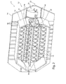
- FIG. 1 shows a perspective view from the front of the ventilation device according to the invention
- FIG. 2 shows a perspective view from the rear of the ventilation device according to FIG. 1,
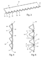
- FIG. 3 is a perspective view of a horizontal lamella
- FIG. 4 shows a perspective view of a vertical lamella
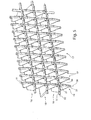
- FIG. 5 shows a perspective view of a plurality of superimposed horizontal and vertical slats
- FIG. 6 shows a schematic side view of the arrangement according to FIG. 5,
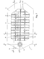
- FIG. 7 shows a schematic view from the front of the ventilation device according to FIG. 1.
- a ventilation device 11 is shown in perspective, which, for example, at the end of a ventilation duct for a ventilation or heating system on an instrument panel component of a motor vehicle can be fastened. Such a ventilation device 11 can also be used for other ventilation or heating systems.
- the ventilation device 11 comprises a housing 12 which, facing the visible side, comprises at least one front-side frame 14 and behind it a box-shaped or tubular housing section 15, as shown in FIG.
- the frame 14 is preferably mountable on the housing section 15.
- This tubular or box-shaped housing portion 15 can be used in a ventilation duct of the ventilation or heating system, not shown.
- the ventilation device 11 is acted upon by an air flow in the direction of the rear side of the ventilation device 11 according to FIG. 2, whereby an outflow direction is given out of a front side of the ventilation device 11 according to FIG.
- the frontal frame 14 is formed simultaneously as a diaphragm, or an optical design element, which may be varied.
- a plurality of horizontal blades 18 and vertical slats 19 are arranged.
- the horizontal louvers 18 and vertical louvers 19 are each preferably aligned parallel to each other.
- the horizontal slats and vertical slats 18, 19 are one above the other or are nested. This results in crossing points 21 between the horizontal louvers 18 and the vertical louvers 19. These intersection points 21 are preferably located in one plane.
- a regulating device 23 For controlling the horizontal slats 18 and vertical slats 19, a regulating device 23 is provided which, for example, has a single control element 24 which can be arranged on the visible side of the ventilation device.
- This single control element 24 is connected to a coupling mechanism 26, which actuates a push rod 27.
- the push rod 27 is aligned horizontally, for example, and acts, for example, on each vertical lamella 19.
- the coupling mechanism 26 is connected to a joint arrangement 28, which hingedly engages the horizontal louvers 18 in order to pivotably actuate them at their horizontal pivot axis 32.
- the operating element 24 is integrated, for example, in the frontal frame 14. This can alternatively be outside.
- the regulating device 23 makes it possible for the horizontal louvers 18 and the vertical louvers 19 to be actuated independently of one another. Likewise, a simultaneous pivoting movement of the horizontal lamella 18 and vertical lamella 19 can be controlled.
- FIG. 3 a perspective view of the horizontal lamella 18 is shown by way of example.
- This horizontal lamella 18 has at its respective end face a bearing pin 31, so that the horizontal lamella 18 is mounted about a pivot pin 32 passing through the pivot pin 32.
- the horizontal lamella 18 has groove-shaped depressions 33 which intersect the pivot axis 32 and form part of a bearing 44 with the vertical lamella 19. Between the groove-shaped recesses 33, a projection 36 may be formed in the outflow direction.
- the geometry and shape of these projections 36 can be adapted to the optics to form an attractive and / or homogeneous optic in the vent field 17.
- a guide surface 37 is formed, which advantageously extends continuously over the length of the horizontal blades 18. This can be done a deflection of the air flow up or down.
- FIG. 4 shows a perspective view of the vertical lamella 19.
- This vertical lamella 19 also has a bearing journal 31 at the respective front end.
- the vertical lamella 19 is arranged pivotably about a pivot axis 38 in the housing 12.
- the vertical lamella 19 has angular or triangular guide surfaces 39, resulting in 39 V-shaped recesses 41 between the juxtaposed pinned guide surfaces. These recesses 41 form a free space for the pivoting mobility of the horizontal lamella 18, as can be seen from FIG.
- axle sections 42 are formed between the spider-shaped guide surfaces 39 axle sections 42 are formed.
- An end face of the peg-shaped guide surfaces 39 pointing in the outflow direction can be adapted to the desired optics of the vent field 17 with respect to the respective geometry and shape.
- FIG. 5 shows a schematic view in which the horizontal louvers 18 and vertical louvers 19 are interlocked.
- the groove-shaped recesses 33 of the horizontal lamella 18 receive the axle sections 42 of the vertical lamella 19 and at the intersection point 21 form a bearing 44, by which the horizontal lamellae 18 and vertical lamella 19 are assigned and fixed to each other, at the same time their respective pivoting of the horizontal lamella 18 about the pivot axis 32 and the vertical lamella 19 is maintained about the pivot axis 38.
- the pivot axes 32 of the horizontal slats 18 and the pivot axes 38 of the vertical slats 19 intersect, these crossing points 21 are preferably all in a common plane.
- FIG. 6 shows a side view of FIG. 5. It makes clear that the pivoting mobility of the horizontal lamella 18 is made possible by the V-shaped recess 41 or by the peg-shaped configuration of the guide surface 39 of the vertical lamella 19.
- the bearing 44 formed in the intersection point 21 thus allows both a pivoting movement of the vertical lamella 19 about its pivot axis 38 and a pivoting movement of the horizontal lamella 19 about its pivot axis 32.
- the front-side frame 14 and the tubular housing portion 15 may each have at their end face facing each other bearing receptacles 46, so that after positioning the horizontal blades 18 on the housing portion 15 and the subsequent arranging the vertical slats 19 by fixing the frame 14 to the housing portion 15 a simple Assembly is given.
- FIG. 7 shows a schematic view from the front of the ventilation device 11 according to FIG. As a result, the homogeneous appearance of the horizontal louvers 18 and vertical louvers 19 becomes clear.
Landscapes
- Engineering & Computer Science (AREA)
- Mechanical Engineering (AREA)
- Chemical & Material Sciences (AREA)
- Combustion & Propulsion (AREA)
- General Engineering & Computer Science (AREA)
- Physics & Mathematics (AREA)
- Thermal Sciences (AREA)
- Air-Flow Control Members (AREA)
Abstract
Die Erfindung betrifft eine Belüftungsvorrichtung mit einem Gehäuse (12), welches Horizontallamellen (18) und Vertikallamellen (19) aufweist, die kreuzweise ineinandergeschachtelt angeordnet sind und mit einer Reguliervorrichtung (23), durch welche zumindest eine Ausströmrichtung ansteuerbar ist, wobei die Horizontallamellen (18) und die Vertikallamellen (19) jeweils um deren Schwenkachse (32, 38) schwenkbar im Gehäuse (12) gelagert sind.
Description
Belüftungsvorrichtung
Die Erfindung betrifft eine Belüftungsvorrichtung zur Ansteuerung einer Ausströmrichtung eines Luftstromes.
Aus der DE 20 12 000 A1 ist eine Belüftungsvorrichtung bekannt, welche insbesondere für ein Instrumententafelbauteil eines Kraftfahrzeuges zur Belüftung eines Innenraumes vorgesehen ist. Diese Belüftungsvorrichtung weist ein äußeres Gehäuse auf, in welchem eine Regelklappe zur Volumenänderung vorgesehen ist. Am Austrittsende des äußeren Gehäuses ist zur Ansteuerung der Strömungsrichtung des ausströmenden Luftstromes ein inneres Gehäuse vorgesehen, welches mehrere, im Abstand zueinander angeordnete Horizontallamellen fest angeordnet in dem inneren Gehäuse aufnimmt. Dieses innere Gehäuse ist um eine horizontale Schwenkachse schwenkbar im äußeren Gehäuse gelagert. Das innere Gehäuse nimmt mehrere im Abstand zueinander angeordnete Vertikallamellen auf, die senkrecht zu den feststehenden Horizontallamellen ausgerichtet sind. Diese Vertikallamellen weisen Schlitze auf, so dass in diese Schlitze die Horizontallamellen einsteckbar sind und die Horizontal- und Vertikallamellen in einer gemeinsamen Ebene in Ausströmrichtung liegen. Die Vertikallamellen sind schwenkbar um eine vertikale Schwenkachse ansteuerbar.
Diese Anordnung weist den Nachteil auf, dass zur Änderung der Strömungsrichtung abweichend zur Horizontalen das innere Gehäuse schwenkbar angesteuert werden muss, wobei dieses innere Gehäuse beispielsweise oben abschnittsweise gegenüber einer stirnseitigen Blende der Belüftungsvorrichtung hervortritt und unten zurücktritt, wodurch der optische Eindruck beeinträchtigt ist. Zudem ist nicht möglich, dass die Horizontallamellen unabhängig von den Vertikallamellen ansteuerbar sind.
Aus der DE 20 2010 000 445 U1 ist eine Belüftungsvorrichtung mit einem multifunktionalen Bedienknopf bekannt, durch welchen die Horizontallamelle, die Vertikallamelle und die Schließklappe verstellbar sind. Dabei sind die Horizontallamellen durch ein Gehäuse ausgebildet, welches auf- und abschwenkbar ist und dahinterliegend im Inneren des Gehäuses der Belüftungsvorrichtung sind die Vertikallamellen separat angeordnet.
Des Weiteren ist aus der DE 102 26 441 B3 und der DE 100 57 421 A1 eine Belüftungsvorrichtung bekannt, bei denen die Horizontal- und Vertikallamellen durch ein einziges Bedienelement ansteuerbar ist, wobei im inneren des Gehäuses die Vertikallamellen angeordnet und getrennt hierzu zur Sichtseite der Belüftungseinrichtung weisend und getrennt von den Vertikallamellen die Horizontallamellen angeordnet sind. Diese Belüftungsvorrichtungen ermöglichen zwar die unabhängige Ansteuerung der Vertikallamellen und der Horizontallamellen aufgrund der räumlich getrennten hintereinander geschalteten Anordnung, jedoch ist dadurch zur Sichtseite hin keine homogene Optik eines Ausströmfeldes der Belüftungsvorrichtung möglich.
Der Erfindung liegt deshalb die Aufgabe zugrunde, eine Belüftungsvorrichtung vorzuschlagen, welche eine flexible Einstellung in der Ausströmrichtung des Luftstroms ermöglicht und eine homogene ansprechende Optik des Ausströmfeldes aufweist.
Diese Aufgabe wird durch eine Belüftungsvorrichtung gelöst, bei welcher die Horizontallamelle und Vertikallamelle kreuzweise ineinandergeschachtelt angeordnet sind, wobei die Horizontallamellen und die Vertikallamellen jeweils um deren Schwenkachse schwenkbar im Gehäuse gelagert sind. Dadurch wird ermöglicht, dass jede Horizontallamelle und jede Vertikallamelle im Gehäuse schwenkbar gelagert wird und durch das kreuzweise Ineinanderschachteln der Horizontallamellen und Vertikallamellen eine homogene Optik des Ausströmfeldes gegeben ist und auch bei Einstellung von verschiedenen Ausströmrichtungen erhalten bleibt.
Eine bevorzugte Ausführungsform der Erfindung sieht vor, dass die Vertikallamellen und die Horizontallamellen in deren Kreuzungspunkten frei zueinander angeordnet sind, so dass deren Einstellung in der gewünschten Ausrichtung leicht einstellbar ist. Alternativ können die Kreuzungspunkte auch eine Lagerstelle bilden, durch welche die Vertikallamelle um die vertikale Schwenkachse und die Horizontallamelle um die horizontale Schwenkachse schwenkbar ist. Diese können auch flexibel gestaltet werden, um zum Beispiel Toleranzen auszugleichen. Dies weist den Vorteil auf, dass durch die kreuzweise Anordnung und Ineinanderschachtelung der Horizontal- und Vertikallamelle sich gegenseitig in den Kreuzungspunkten durch die Lagerstelle abstützt, so dass eine stabile und gleichbleibende Gitterstruktur aufrechterhalten ist. Gleichzeitig kann dadurch in einfacher Weise die gegenseitige Auslenkung zueinander gesichert werden.
Vorteilhafterweise ist der Kreuzungspunkt durch eine nutenförmige Vertiefung in der Horizontal- oder Vertikallamelle gebildet, in welche ein Lagerzapfen der Horizontal- oder Vertikallamelle aufgenommen ist. Diese Ausgestaltung weist den Vorteil auf, dass der Kreuzungspunkt, insbesondere wenn dieser eine Lagerstelle bildet, von der Sichtseite der Belüftungsvorrichtung nahezu nicht wahrgenommen wird und optisch in den Hintergrund rückt, wodurch die homogene Optik des Ausströmfeldes verstärkt werden kann. Vorteilhafterweise kann eine Lagerstelle ohne zusätzliche Lagerelemente gebildet werden.
Eine weitere bevorzugte Ausgestaltung der Belüftungsvorrichtung sieht vor, dass die Horizontal- oder Vertikallamelle eine V-förmige Aussparung ausweist, welche sich entgegen der Ausströmrichtung ausgehend von einem Kreuzungspunkt der Horizontal- und Vertikallamelle erstreckt. Diese V-förmige Aussparung ermöglicht, ausgehend von dem Kreuzungspunkt der Horizontal- und Vertikallamelle, jeweils eine Schwenkbeweglichkeit, so dass die Horizontallamelle um die horizontale Schwenkachse und die Vertikallamelle um die vertikale Schwenkachse zur Ansteuerung der Ausströmrichtung verschwenkbar ist.
Bevorzugt weist die Horizontal- oder Vertikallamelle entlang deren Schwenkachse und entgegen der Ausströmrichtung weisend dreieckige oder wimpelförmige Leitflächen auf. Diese dreieckförmigen oder wimpelförmigen Leitflächen resultieren aus den V-förmigen Aussparungen und ermöglichen, dass durch die V-förmig gebildete Aussparung der Schwenkbereich der Horizontallamelle bestimmt wird. Alternativ können die Leitflächen auch im Anschluss an eine dreieckförmige oder wimpelförmige Leitfläche eine sich vergrößernde Leitfläche umfassen, welche entgegen der Ausströmrichtung sich erstreckt. Anders ausgedrückt, kann die Vertikallamelle nur bereichsweise eine Reduzierung der Breite der Leitfläche aufweisen, um einen Schwenkbereich für die Horizontallamelle zu bilden.
Die Horizontal- und/oder Vertikallamelle weisen entlang der Schwenkachse aneinandergereihte dreiecksförmige Leitflächen auf, welche durch Achsabschnitte miteinander verbunden sind. Bevorzugt ist die Horizontal- oder Vertikallamelle einteilig aus Kunststoff als Kunststoffspritzgussteil ausgebildet, so dass sowohl die Leitflächen als auch die Lagerzapfen miteinander integriert sein können.
Die Horizontal- oder Vertikallamelle weist bevorzugt entlang der Längsachse und an die Kreuzungspunkte angrenzend eine durchgehend ausgebildete Leitfläche auf, die sich entgegen der Ausströmrichtung erstreckt. Bevorzugt ist die längere Lamelle von den beiden Lamellen mit der durchgehend ausgebildeten Leitfläche ausgebildet.
Die Schwenkachse der Horizontallamelle und die Schwenkachse der Vertikallamelle kreuzen sich vorzugsweise in den Kreuzungspunkten. Dadurch wird das Übereinanderlegen der Horizontal- und Vertikallamelle im Aufbau vereinfacht.
Des Weiteren ist bevorzugt vorgesehen, dass die Schwenkachse der Horizontal- und Vertikallamellen in einer gemeinsamen Ebene liegen. Diese Anordnung ermöglicht ein flachbauendes Gehäuse, d.h. dass ausgehend von einer Abdeckplatte oder –blende an der Sichtseite der Belüftungseinrichtung nur ein geringer Bauraum erforderlich ist, der in den Belüftungskanal der Lüftungsanlage hineinragt.
Die Horizontallamellen sind bevorzugt durch eine Gelenkanordnung gemeinsam ansteuerbar. Dies weist den Vorteil auf, dass eine Koppelstelle zur Krafteinleitung genügt, um alle Horizontallamellen gleichzeitig anzusteuern.
Die Vertikallamellen sind beispielsweise über eine gemeinsame Schubstange ansteuerbar, so dass eine Bewegung der Schubstange in der horizontalen Richtung genügt, um eine seitliche Ausströmungsrichtung anzusteuern.
Zur Ansteuerung der Horizontal- und Vertikallamelle ist gemäß einer ersten Ausführungsform eine Reguliereinrichtung vorgesehen, welches jeweils ein Stellelement für die Horizontal- und Vertikallamellen aufweist.
Alternativ kann vorgesehen sein, dass die Reguliervorrichtung ein einziges Bedienelement aufweist, welches über ein Koppelgetriebe die Gelenkanordnung zur Ansteuerung der Horizontallamellen und die Schubstange zur Ansteuerung der Vertikallamellen ansteuert, wobei das Koppelgetriebe nur eine Verstellung der Vertikallamellen oder der Horizontallamellen oder auch beide gleichzeitig ansteuerbar sind. Eine solche Ansteuerung kann auch als eine Joystick-Bedienung bezeichnet werden.
Des Weiteren kann vorgesehen sein, dass die Reguliervorrichtung zumindest einen elektrischen Stellantrieb aufweist, durch welchen oder welche die Verstellung der Horizontallamellen und/oder der Vertikallamellen ansteuerbar sind.
Eine alternative Ausgestaltung der Belüftungsvorrichtung sieht vor, dass ein oder mehrere Vertikallamellen und/oder ein oder mehrere Horizontallamellen gegenläufig zueinander in der Ausströmrichtung ansteuerbar sind. Dadurch kann beispielsweise jede zweite Lamelle gegenläufig zur benachbarten Lamelle angesteuert werden oder jede dritte oder vierte usw., wodurch eine diffuse Ausströmung des Luftstromes erzielt werden kann.
Zur Ansteuerung der gegenläufig ausgerichteten Vertikal- und/oder Horizontallamellen zur Bildung einer diffusen Ausströmung können eine oder mehrere Schubstangen und eine oder mehrere Gelenkanordnungen vorgesehen sein, um die Einstellung vorzunehmen. Dabei kann die Gelenkvorrichtung manuell betätigbar sein oder durch zumindest einen elektrischen Antrieb angesteuert werden. Ebenso ist auch ein Koppelgetriebe zum gemeinsamen Ansteuern möglich.
Die Erfindung sowie weitere vorteilhafte Ausführungsformen und Weiterbildungen derselben werden im Folgenden anhand der in den Zeichnungen dargestellten Beispiele näher beschrieben und erläutert. Die der Beschreibung und den Zeichnungen zu entnehmenden Merkmale können einzeln für sich oder zu mehreren in beliebiger Kombination erfindungsgemäß angewandt werden. Es zeigen:
Figur 1 eine perspektivische Ansicht von vorne auf die erfindungsgemäße Belüftungseinrichtung,
Figur 2 eine perspektivische Ansicht von hinten auf die Belüftungseinrichtung gemäß Figur 1,
Figur 3 eine perspektivische Ansicht einer Horizontallamelle,
Figur 4 eine perspektivische Ansicht einer Vertikallamelle,
Figur 5 eine perspektivische Ansicht von mehreren übereinanderliegende Horizontal- und Vertikallamellen,
Figur 6 eine schematische Seitenansicht der Anordnung gemäß Figur 5,
Figur 7 eine schematische Ansicht von vorne auf die Belüftungsvorrichtung gemäß Figur 1.
In Figur 1 ist perspektivisch eine Belüftungsvorrichtung 11 dargestellt, welche beispielsweise am Ende eines Lüftungskanals für ein Belüftungs- beziehungsweise Heizsystem an einem Instrumententafelbauteil eines Kraftfahrzeuges befestigbar ist. Eine solche Belüftungsvorrichtung 11 kann auch für weitere Belüftungs- oder Heizsysteme eingesetzt werden.
Die Belüftungsvorrichtung 11 umfasst ein Gehäuse 12, welches zur Sichtseite weisend zumindest einen stirnseitigen Rahmen 14 und dahinterliegend einen kasten- oder rohrförmigen Gehäuseabschnitt 15 umfasst, wie aus Figur 2 hervorgeht. Der Rahmen 14 ist bevorzugt auf dem Gehäuseabschnitt 15 montierbar.
Dieser rohr- oder kastenförmige Gehäuseabschnitt 15 ist in einem nicht näher dargestellten Lüftungskanal der Belüftungs- oder Heizsystems einsetzbar. Die Belüftungseinrichtung 11 wird mit einem Luftstrom in Richtung auf die Rückseite der Belüftungseinrichtung 11 gemäß Figur 2 beaufschlagt, wodurch eine Ausströmrichtung aus einer Vorderseite der Belüftungsvorrichtung 11 gemäß Figur 1 heraus gegeben ist.
Im Ausführungsbeispiel ist der stirnseitige Rahmen 14 gleichzeitig als eine Blende, bzw. ein optisches Gestaltungselement ausgebildet, welche mannigfaltig sein kann.
In einem durch den rohrförmigen Gehäuseabschnitt 15 gebildeten Ausströmerfeld 17 sind eine Vielzahl von Horizontallamellen 18 und Vertikallamellen 19 angeordnet. Die Horizontallamellen 18 und Vertikallamellen 19 sind jeweils bevorzugt parallel zueinander ausgerichtet. Die Horizontallamellen und Vertikallamellen 18, 19 liegen übereinander beziehungsweise sind ineinander geschachtelt. Dadurch entstehen zwischen den Horizontallamellen 18 und den Vertikallamellen 19 Kreuzungspunkte 21. Bevorzugt liegen dieses Kreuzungspunkte 21 in einer Ebene.
Zur Ansteuerung der Horizontallamellen 18 und Vertikallamellen 19 ist eine Reguliereinrichtung 23 vorgesehen, welche beispielsweise ein einziges Bedienelement 24 aufweist, das auf der Sichtseite der Belüftungseinrichtung angeordnet sein kann. Dieses einzige Bedienelement 24 steht mit einem Koppelgetriebe 26 in Verbindung, welches eine Schubstange 27 betätigt. Die Schubstange 27 ist beispielsweise horizontal ausgerichtet und greift beispielsweise an jeder Vertikallamelle 19 an. Des Weiteren steht das Koppelgetriebe 26 mit einer Gelenkanordnung 28 in Verbindung, welche gelenkig an den Horizontallamellen 18 angreift, um diese an deren horizontale Schwenkachse 32 schwenkbar anzusteuern.
Das Bedienelement 24 ist beispielsweise in den stirnseitigen Rahmen 14 integriert. Dieses kann alternativ auch außerhalb liegen.
Die Reguliereinrichtung 23 ermöglicht, dass die Horizontallamellen 18 und die Vertikallamellen 19 jeweils unabhängig voneinander ansteuerbar sind. Ebenso kann eine gleichzeitige Schwenkbewegung der Horizontallamelle 18 und Vertikallamelle 19 angesteuert werden.
In Figur 3 ist beispielhaft eine perspektivische Ansicht der Horizontallamelle 18 dargestellt. Diese Horizontallamelle 18 weist an deren jeweiligen stirnseitigen Ende einen Lagerzapfen 31 auf, so dass die Horizontallamelle 18 um eine die Lagerzapfen 31 durchquerende Schwenkachse 32 gelagert ist. Die Horizontallamelle 18 weist des Weiteren die Schwenkachse 32 durchbrechende nutenförmige Vertiefungen 33 auf, welche ein Teil einer Lagerstelle 44 mit der Vertikallamelle 19 bilden. Zwischen den nutenförmigen Vertiefungen 33 kann in Ausströmrichtung ein Vorsprung 36 ausgebildet sein. Die Geometrie und Form dieser Vorsprünge 36 kann an die Optik angepasst werden, um eine ansprechende und/oder homogene Optik im Ausströmerfeld 17 zu bilden. An die nutenförmigen Vertiefungen 33 anschließend und entgegengesetzt zur Ausströmrichtung sich erstreckend ist eine Leitfläche 37 ausgebildet, welche vorteilhafterweise sich durchgehend über die Länge der Horizontallamellen 18 erstreckt. Dadurch kann eine Ablenkung der Luftströmung nach oben oder unten erfolgen.
In Figur 4 ist eine perspektivische Ansicht der Vertikallamelle 19 dargestellt. Diese Vertikallamelle 19 weist am jeweiligen stirnseitigen Ende ebenfalls einen Lagerzapfen 31 auf. Dadurch ist die Vertikallamelle 19 um eine Schwenkachse 38 im Gehäuse 12 schwenkbar angeordnet. Die Vertikallamelle 19 weist winkelförmige oder dreieckförmige Leitflächen 39 auf, wodurch sich zwischen den aneinander gereihten wimpelförmigen Leitflächen 39 V-förmige Aussparungen 41 ergeben. Diese Aussparungen 41 bilden einen Freiraum für die Schwenkbeweglichkeit der Horizontallamelle 18, wie aus Figur 6 ersichtlich ist. Zwischen den wimpelförmigen Leitflächen 39 sind Achsabschnitte 42 ausgebildet. Eine Stirnseite der wimpelförmigen Leitflächen 39 in Ausströmrichtung weisend kann bezüglich der jeweiligen Geometrie und Form an gewünschte Optik des Ausströmerfeldes 17 angepasst werden.
In Figur 5 ist eine schematische Ansicht dargestellt, bei welcher die Horizontallamellen 18 und Vertikallamellen 19 ineinander gesetzt sind. Dabei nehmen die nutenförmigen Vertiefungen 33 der Horizontallamelle 18 die Achsabschnitte 42 der Vertikallamelle 19 auf und bilden im Kreuzungspunkt 21 eine Lagerstelle 44, durch welche die Horizontallamelle 18 und Vertikallamelle 19 einander zugeordnet und fixiert sind, wobei gleichzeitig deren jeweiligen Schwenkbarkeit der Horizontallamelle 18 um die Schwenkachse 32 und der Vertikallamelle 19 um die Schwenkachse 38 erhalten bleibt. Die Schwenkachsen 32 der Horizontallamellen 18 und die Schwenkachsen 38 der Vertikallamellen 19 schneiden sich, wobei diese Kreuzungspunkte 21 bevorzugt alle in einer gemeinsamen Ebene liegen. Durch diese Ineinanderschachtelung der Horizontallamelle 18 und Vertikallamelle 19 wird gemäß Figur 5 offensichtlich, dass die Vertikallamelle 19 um die Schwenkachse 38 schwenkbar ist, unabhängig von der Ausrichtung der Horizontallamelle 18.
Figur 6 stellt eine Seitenansicht zu Figur 5 dar. Darin wird verdeutlicht, dass durch die V-förmige Aussparung 41, beziehungsweise durch die wimpelförmige Ausgestaltung der Leitfläche 39 der Vertikallamelle 19 die Schwenkbeweglichkeit der Horizontallamelle 18 ermöglicht ist. Die im Kreuzungspunkt 21 gebildete Lagerstelle 44 ermöglicht also sowohl eine Schwenkbewegung der Vertikallamelle 19 um deren Schwenkachse 38 als auch eine Schwenkbewegung der Horizontallamelle 19 um deren Schwenkachse 32.
Der stirnseitige Rahmen 14 und der rohrförmige Gehäuseabschnitt 15 können jeweils an deren aufeinander zuweisenden Stirnfläche Lageraufnahmen 46 aufweisen, so dass nach dem Positionieren der Horizontallamellen 18 auf dem Gehäuseabschnitt 15 und dem darauffolgenden Anordnen der Vertikallamellen 19 durch eine Fixierung des Rahmens 14 zum Gehäuseabschnitt 15 ein einfacher Zusammenbau gegeben ist.
In Figur 7 ist eine schematische Ansicht von vorne auf die Belüftungsvorrichtung 11 gemäß Figur 1 dargestellt. Dadurch wird die homogene Optik der Horizontallamellen 18 und Vertikallamellen 19 deutlich.
Claims (15)
- Belüftungsvorrichtung mit einem Gehäuse (12), welches Horizontallamellen (18) und Vertikallamellen (19) aufweist, die kreuzweise ineinandergeschachtelt angeordnet sind und mit einer Reguliervorrichtung (23), durch welche zumindest eine Ausströmrichtung ansteuerbar ist, dadurch gekennzeichnet, dass die Horizontallamellen (18) und die Vertikallamellen (19) jeweils um deren Schwenkachse (32, 38) schwenkbar im Gehäuse (12) gelagert sind.
- Belüftungsvorrichtung nach Anspruch 1, dadurch gekennzeichnet, dass die Horizontallamelle (18) und die Vertikallamelle (19) durch die kreuzweise Ineinanderschachtelung einen Kreuzungspunkt (21) aufweisen, in dem diese frei zueinander angeordnet sind oder in welchem eine Lagerstelle (44) gebildet ist, durch welche die Vertikallamelle (19) um die vertikale Schwenkachse (38) und die Horizontallamelle (18) um die horizontale Schwenkachse (32) schwenkbar ist.
- Belüftungsvorrichtung nach Anspruch 2, dadurch gekennzeichnet, dass der Kreuzungspunkt (21) durch eine nutenförmige Vertiefung (33) in der Horizontallamelle (18) oder Vertikallamelle (19) gebildet ist, in welchem ein Achsabschnitt (42) der Vertikallamelle (19) oder Horizontallamelle (18) aufgenommen ist.
- Belüftungsvorrichtung nach einem der vorherigen Ansprüche, dadurch gekennzeichnet, dass die Vertikallamelle (19) oder Horizontallamelle (18) eine V-förmige Aussparung (41) aufweist, welche sich ausgehend von einem Kreuzungspunkt (21) entgegen der Ausströmrichtung erstreckt und vorzugsweise entgegen der Ausströmrichtung sich aufweitet.
- Belüftungsvorrichtung nach einem der vorherigen Ansprüche, dadurch gekennzeichnet, dass die Horizontallamelle (18) oder Vertikallamelle (19) entlang der Schwenkachse (32, 38) und entgegen der Ausströmrichtung weisend eine dreiecksförmige oder wimpelförmige Leitfläche (39) oder einen sich daran anschließenden und entgegen der Ausströmrichtung sich erstreckenden und vorzugsweise sich vergrößernden Leitflächenabschnitt aufweist, der sich aufweitet.
- Belüftungsvorrichtung nach Anspruch 5, dadurch gekennzeichnet, dass die Horizontallamelle (18) oder Vertikallamelle (19) entlang der Schwenkachse (32, 38) aneinandergereihte Leitflächen (39) aufweist, welche durch Achsabschnitte (42) miteinander verbunden sind.
- Belüftungsvorrichtung nach einem der vorhergehenden Ansprüche, dadurch gekennzeichnet, dass die Vertikallamelle (19) oder Horizontallamelle (18) entlang der Schwenkachse (32, 38) und an die Kreuzungspunkte (21) angrenzend eine durchgehend ausgebildete Leitfläche (37) aufweist, die sich entgegen der Ausströmrichtung erstreckt.
- Belüftungsvorrichtung nach einem der vorhergehenden Ansprüche, dadurch gekennzeichnet, dass die Schwenkachse (32) der Horizontallamelle (18) oder die Schwenkachse (38) der Vertikallamelle (19) sich kreuzen und Kreuzungspunkte (21) bilden.
- Belüftungsvorrichtung nach einem der vorhergehenden Ansprüche, dadurch gekennzeichnet, dass die Schwenkachse (32) der Horizontallamelle (18) und die Schwenkachse (38) der Vertikallamelle (19) in einer gemeinsamen Ebene liegen.
- Belüftungsvorrichtung nach einem der vorhergehenden Ansprüche, dadurch gekennzeichnet, dass die Horizontallamellen (18) durch eine Gelenkanordnung (28) gemeinsam ansteuerbar sind.
- Belüftungsvorrichtung nach einem der vorhergehenden Ansprüche, dadurch gekennzeichnet, dass die Vertikallamellen (19) durch eine Schubstange (27) gemeinsam ansteuerbar ist.
- Belüftungsvorrichtung nach einem der Ansprüche 10 oder 11, dadurch gekennzeichnet, dass die Reguliereinrichtung (23) jeweils ein Stellelement für die Gelenkanordnung (28) und Schubstange (27) aufweist.
- Belüftungsvorrichtung nach Anspruch 10 oder 11, dadurch gekennzeichnet, dass die Reguliereinrichtung (23) ein einziges Bedienelement (24) aufweist, welches über ein Koppelgetriebe (26) die Gelenkanordnung (28) und die Schubstange (27) zum Einstellen der Ausströmrichtung ansteuert, wobei durch das Koppelgetriebe (26) nur die Verstellung der Vertikallamelle (19) oder der Horizontallamelle (18) oder beide gleichzeitig ansteuerbar sind.
- Belüftungsvorrichtung nach einem der Ansprüche 1 bis 12, dadurch gekennzeichnet, dass die Reguliervorrichtung (23) zumindest einen elektrischen Antrieb aufweist, welcher die Schubstange (27) und die Gelenkanordnung (28) einzeln oder gemeinsam ansteuert.
- Belüftungsvorrichtung nach einem der Ansprüche 1 bis 9, dadurch gekennzeichnet, dass ein oder mehrere Horizontallamellen (18) und/oder ein oder mehrere Vertikallamellen (19) gegenläufig zueinander in der Ausströmrichtung ansteuerbar sind, und vorzugsweise die Horizontallamellen (18) und die Vertikallamellen (19) mit einer oder mehreren Schubstangen (27) und mit einer oder mehreren Gelenkanordnungen (28) durch die Reguliervorrichtung (22) manuell oder durch zumindest elektrischen Antrieb oder ein Koppelgetriebe ansteuerbar sind.
Priority Applications (3)
| Application Number | Priority Date | Filing Date | Title |
|---|---|---|---|
| CN201580049297.3A CN106796048A (zh) | 2014-08-07 | 2015-07-17 | 通风装置 |
| EP15738910.7A EP3164280B1 (de) | 2014-08-07 | 2015-07-17 | Belüftungsvorrichtung |
| US15/423,796 US10948216B2 (en) | 2014-08-07 | 2017-02-03 | Ventilation device |
Applications Claiming Priority (2)
| Application Number | Priority Date | Filing Date | Title |
|---|---|---|---|
| DE202014103672.5U DE202014103672U1 (de) | 2014-08-07 | 2014-08-07 | Belüftungsvorrichtung |
| DE202014103672.5 | 2014-08-07 |
Related Child Applications (1)
| Application Number | Title | Priority Date | Filing Date |
|---|---|---|---|
| US15/423,796 Continuation US10948216B2 (en) | 2014-08-07 | 2017-02-03 | Ventilation device |
Publications (1)
| Publication Number | Publication Date |
|---|---|
| WO2016020171A1 true WO2016020171A1 (de) | 2016-02-11 |
Family
ID=53673946
Family Applications (1)
| Application Number | Title | Priority Date | Filing Date |
|---|---|---|---|
| PCT/EP2015/066421 Ceased WO2016020171A1 (de) | 2014-08-07 | 2015-07-17 | Belüftungsvorrichtung |
Country Status (5)
| Country | Link |
|---|---|
| US (1) | US10948216B2 (de) |
| EP (1) | EP3164280B1 (de) |
| CN (1) | CN106796048A (de) |
| DE (1) | DE202014103672U1 (de) |
| WO (1) | WO2016020171A1 (de) |
Families Citing this family (7)
| Publication number | Priority date | Publication date | Assignee | Title |
|---|---|---|---|---|
| DE102017120208B3 (de) | 2017-09-01 | 2018-06-28 | GRAMMER Interior Components GmbH | Luftausströmer für Fahrzeuginnenräume |
| DE102018124748B4 (de) * | 2017-11-24 | 2023-02-09 | Hanon Systems | Mehrzonenklimaanlage für Fahrzeuge |
| CN108489063B (zh) * | 2018-03-23 | 2020-11-10 | 海信(山东)空调有限公司 | 一种导风叶片及空调器 |
| DE102019106086B4 (de) | 2019-03-11 | 2023-06-22 | GRAMMER Interior Components GmbH | Luftausströmer für den Innenraum eines Kraftfahrzeuges |
| CN110171436A (zh) * | 2019-07-08 | 2019-08-27 | 袁可 | 一种高铁出风口 |
| JP7493358B2 (ja) * | 2020-03-18 | 2024-05-31 | 豊和化成株式会社 | レジスタ |
| KR20240054721A (ko) * | 2022-10-19 | 2024-04-26 | 현대자동차주식회사 | 가변 그릴 장치 |
Citations (9)
| Publication number | Priority date | Publication date | Assignee | Title |
|---|---|---|---|---|
| US2892395A (en) * | 1958-06-23 | 1959-06-30 | Adam D Goettl | Air directing louver device |
| US2959117A (en) * | 1959-01-26 | 1960-11-08 | Wright Mfg Co | Louver assembly |
| GB885918A (en) * | 1957-01-25 | 1962-01-03 | Derek Richard Barker | Improvements in or relating to ventilator grilles |
| DE2012000A1 (de) | 1969-03-21 | 1971-02-04 | Rootes Motors Ltd , London | Allseitig einstellbare Beluftungsvor richtung |
| GB2196421A (en) * | 1986-07-18 | 1988-04-27 | Clearplas Ltd | Directional air vent |
| US6159092A (en) * | 1998-08-31 | 2000-12-12 | Fickenscher America, L.L.C. | Air vent having two coplanar vane sets |
| DE10057421A1 (de) | 2000-11-20 | 2002-05-29 | Trw Automotive Electron & Comp | Luftaustritt für Belüftungsanlagen |
| DE10226441B3 (de) | 2002-06-13 | 2004-03-25 | Peguform Gmbh & Co. Kg I.Ins. | Belüftungseinrichtung |
| DE202010000445U1 (de) | 2010-03-23 | 2010-07-15 | Dr. Schneider Kunststoffwerke Gmbh | Belüftungsdüse mit einem multifunktionalen Bedienknopf |
Family Cites Families (45)
| Publication number | Priority date | Publication date | Assignee | Title |
|---|---|---|---|---|
| US3120797A (en) * | 1960-06-06 | 1964-02-11 | Ford Motor Co | Vehicle ventilation system |
| JPH04349021A (ja) * | 1990-08-02 | 1992-12-03 | Mazda Motor Corp | 車両用空気調和装置 |
| EP0630328B1 (de) * | 1992-03-17 | 1998-12-16 | Bowles Fluidics Corporation | Düse und verfahren zur belüftung |
| US5558949A (en) * | 1993-12-27 | 1996-09-24 | Honda Giken Kogyo Kabushiki Kaisha | Battery box |
| DE69609459T2 (de) * | 1995-07-17 | 2000-12-21 | Ford France S.A., Rueil-Malmaison | Luftausströmorgan |
| US5639571A (en) * | 1996-06-24 | 1997-06-17 | General Motors Corporation | Battery pack |
| DE19701499C1 (de) * | 1997-01-17 | 1997-12-11 | Daimler Benz Ag | Belüftungsdüse für Fahrzeuge |
| JP3952597B2 (ja) * | 1997-08-08 | 2007-08-01 | 株式会社デンソー | 車両用空調装置 |
| JP4277172B2 (ja) * | 2002-06-21 | 2009-06-10 | 豊田合成株式会社 | 空調用レジスタ |
| DE20210038U1 (de) * | 2002-06-28 | 2002-11-14 | TRW Automotive Electronics & Components GmbH & Co.KG, 67677 Enkenbach-Alsenborn | Luftaustritt |
| TWI282139B (en) * | 2002-07-01 | 2007-06-01 | Advanced Display Kabushiki Kai | Carrying vehicle, manufacturing apparatus, and carrying system |
| US6830511B2 (en) * | 2003-01-21 | 2004-12-14 | Collins & Aikman Products Co. | Air duct outlets with remotely-located joystick louver controls |
| US6857953B2 (en) * | 2002-12-02 | 2005-02-22 | Dometic Corporation | Return air apparatus with down draft diverter |
| US20040259493A1 (en) * | 2003-06-20 | 2004-12-23 | Valley Charles Richard | Method and apparatus for negative pressure ventilation in vehicles |
| KR20050017879A (ko) * | 2003-08-11 | 2005-02-23 | 현대모비스 주식회사 | 자동차의 에어밴트 개폐장치 |
| US7025159B2 (en) * | 2003-09-12 | 2006-04-11 | Ford Global Technologies, Llc | Cooling system for a vehicle battery |
| CN2655098Y (zh) * | 2003-11-16 | 2004-11-10 | 罗启康 | 中央空调电控出风口 |
| JP4379188B2 (ja) * | 2004-04-22 | 2009-12-09 | 豊田合成株式会社 | 空調用レジスタ |
| DE102005027746A1 (de) * | 2005-06-16 | 2006-12-21 | Volkswagen Ag | Luftausströmer für den Fahrgastraum eines Fahrzeuges |
| CN2903774Y (zh) * | 2006-03-20 | 2007-05-23 | 顾红 | 延伸型快速插接风口 |
| DE102007035507A1 (de) * | 2007-07-28 | 2009-01-29 | Bayerische Motoren Werke Aktiengesellschaft | Kraftfahrzeug-Belüftungseinrichtung |
| US8100209B2 (en) * | 2008-03-31 | 2012-01-24 | Honda Motor Co., Ltd. | Front bulkhead cover and air flow system |
| US8550887B2 (en) * | 2009-09-18 | 2013-10-08 | Lacks Enterprises, Inc. | Vehicle grill with moveable louvers |
| JP4886832B2 (ja) * | 2009-10-16 | 2012-02-29 | 本田技研工業株式会社 | ダクトの配設構造 |
| CN202018109U (zh) * | 2011-03-03 | 2011-10-26 | 尤飞鹏 | 一种出风口结构 |
| EP2503257B9 (de) * | 2011-03-22 | 2014-06-04 | Erwin Gasser | Shelter |
| US20120270490A1 (en) * | 2011-04-21 | 2012-10-25 | GM Global Technology Operations LLC | System and method of shutter control |
| DE102011078691B4 (de) * | 2011-07-05 | 2026-03-26 | Röchling Automotive SE | Luftleiteinrichtung für ein Kraftfahrzeug |
| CN202216372U (zh) * | 2011-08-01 | 2012-05-09 | 徐杰 | 风动百叶风口 |
| JP5980211B2 (ja) * | 2011-08-20 | 2016-08-31 | 株式会社Ams | 車両用グリル |
| DE102011115178B4 (de) * | 2011-09-28 | 2014-10-09 | Audi Ag | Luftausströmer eines Lüftungs- und Heizungsmoduls für Kraftfahrzeuge mit einer Umschaltung zwischen einer Spotstellung und einer Diffusstellung |
| US9557072B2 (en) * | 2011-10-28 | 2017-01-31 | Dometic Sweden Ab | Vent cover |
| JP2013193603A (ja) * | 2012-03-21 | 2013-09-30 | Aisin Seiki Co Ltd | グリルシャッタ装置 |
| GB2502132B (en) * | 2012-05-17 | 2014-11-05 | Dyson Technology Ltd | Autonomous vacuum cleaner |
| DE102012214474B4 (de) * | 2012-08-14 | 2017-08-31 | Magna Exteriors (Germany) Gmbh | Steuerbarer Lufteinlass für ein Kraftfahrzeug |
| US20140113536A1 (en) * | 2012-10-23 | 2014-04-24 | Visteon Global Technologies, Inc. | Zonal airflow system for a vehicle |
| JP6089708B2 (ja) * | 2013-01-10 | 2017-03-08 | アイシン精機株式会社 | 車両用グリル装置 |
| US10029558B2 (en) * | 2013-03-15 | 2018-07-24 | Srg Global, Inc. | Grille shutter assembly |
| CN203375644U (zh) * | 2013-06-07 | 2014-01-01 | 广东美的制冷设备有限公司 | 空调导风机构及空调器 |
| US10363811B2 (en) * | 2013-06-13 | 2019-07-30 | Ford Global Technologies, Llc | Vehicle speed controlled active grille shutter system |
| KR20150049152A (ko) * | 2013-10-29 | 2015-05-08 | 현대자동차주식회사 | 자동차의 기류 유도 장치 |
| US9590228B1 (en) * | 2013-11-01 | 2017-03-07 | HRL Laboratroies, LLC | Three-dimensional micro-lattice battery structures with convective flow of electrolytes |
| US20150353052A1 (en) * | 2014-06-04 | 2015-12-10 | Ford Global Technologies, Llc | Defroster nozzle with net over outlet |
| JP6417188B2 (ja) * | 2014-10-31 | 2018-10-31 | ダイキョーニシカワ株式会社 | 車両のデフロスタ構造 |
| US20160200174A1 (en) * | 2015-01-08 | 2016-07-14 | Airxcel, Inc. | Air vent assembly and method |
-
2014
- 2014-08-07 DE DE202014103672.5U patent/DE202014103672U1/de not_active Expired - Lifetime
-
2015
- 2015-07-17 WO PCT/EP2015/066421 patent/WO2016020171A1/de not_active Ceased
- 2015-07-17 CN CN201580049297.3A patent/CN106796048A/zh active Pending
- 2015-07-17 EP EP15738910.7A patent/EP3164280B1/de active Active
-
2017
- 2017-02-03 US US15/423,796 patent/US10948216B2/en active Active
Patent Citations (9)
| Publication number | Priority date | Publication date | Assignee | Title |
|---|---|---|---|---|
| GB885918A (en) * | 1957-01-25 | 1962-01-03 | Derek Richard Barker | Improvements in or relating to ventilator grilles |
| US2892395A (en) * | 1958-06-23 | 1959-06-30 | Adam D Goettl | Air directing louver device |
| US2959117A (en) * | 1959-01-26 | 1960-11-08 | Wright Mfg Co | Louver assembly |
| DE2012000A1 (de) | 1969-03-21 | 1971-02-04 | Rootes Motors Ltd , London | Allseitig einstellbare Beluftungsvor richtung |
| GB2196421A (en) * | 1986-07-18 | 1988-04-27 | Clearplas Ltd | Directional air vent |
| US6159092A (en) * | 1998-08-31 | 2000-12-12 | Fickenscher America, L.L.C. | Air vent having two coplanar vane sets |
| DE10057421A1 (de) | 2000-11-20 | 2002-05-29 | Trw Automotive Electron & Comp | Luftaustritt für Belüftungsanlagen |
| DE10226441B3 (de) | 2002-06-13 | 2004-03-25 | Peguform Gmbh & Co. Kg I.Ins. | Belüftungseinrichtung |
| DE202010000445U1 (de) | 2010-03-23 | 2010-07-15 | Dr. Schneider Kunststoffwerke Gmbh | Belüftungsdüse mit einem multifunktionalen Bedienknopf |
Also Published As
| Publication number | Publication date |
|---|---|
| DE202014103672U1 (de) | 2015-11-10 |
| US10948216B2 (en) | 2021-03-16 |
| EP3164280A1 (de) | 2017-05-10 |
| EP3164280B1 (de) | 2018-11-07 |
| US20170176046A1 (en) | 2017-06-22 |
| CN106796048A (zh) | 2017-05-31 |
Similar Documents
| Publication | Publication Date | Title |
|---|---|---|
| EP3164280B1 (de) | Belüftungsvorrichtung | |
| EP3403859B1 (de) | Luftausströmer | |
| DE102011115178B4 (de) | Luftausströmer eines Lüftungs- und Heizungsmoduls für Kraftfahrzeuge mit einer Umschaltung zwischen einer Spotstellung und einer Diffusstellung | |
| EP3762245B1 (de) | Luftausströmer, modul und luftausströmeranordnung | |
| EP3063026A1 (de) | Luftdüse | |
| EP3321113B1 (de) | Luftausströmer | |
| EP3192684A1 (de) | Einrichtung zum verstellen von lamellen eines luftausströmers | |
| DE102012015519A1 (de) | Luftleitvorrichtung für eine Luftausströmvorrichtung eines Fahrzeugs | |
| EP1497147B1 (de) | Bel ftungseinrichtung | |
| EP3530505B1 (de) | Luftausströmer | |
| DE102020131095A1 (de) | Lüftungseinrichtung | |
| EP2602137B1 (de) | Luftauslassvorrichtung für den Innenraum eines Fahrzeugs | |
| WO2020234031A1 (de) | Luftauslasseinheit für eine fahrzeuglüftung und fahrzeug | |
| DE102019116668A1 (de) | Ausströmdüse eines Kraftfahrzeugs | |
| DE102021111535A1 (de) | Luftausströmeranordnung | |
| DE102010023528B4 (de) | Luftausströmvorrichtung für ein Fahrzeug | |
| DE102010014075B4 (de) | Belüftungsdüse für den Innenraum eines Kraftfahrzeugs | |
| DE202008008817U1 (de) | Luftdüse zum Leiten eines Luftstromes | |
| DE102023103893B4 (de) | Luftausströmer mit einstellbarer Luftaustrittsrichtung | |
| EP0949099A2 (de) | Luftstromverteiler für einen Kraftfahrzeuginnenraum | |
| DE102019201270A1 (de) | Belüftungssystem | |
| EP3790749B1 (de) | Ausströmer für ein fahrzeug | |
| DE202023100756U1 (de) | Luftausströmer mit einstellbarer Luftaustrittsrichtung | |
| DE102006010388A1 (de) | Belüftungsvorrichtung | |
| DE102017120208B3 (de) | Luftausströmer für Fahrzeuginnenräume |
Legal Events
| Date | Code | Title | Description |
|---|---|---|---|
| 121 | Ep: the epo has been informed by wipo that ep was designated in this application |
Ref document number: 15738910 Country of ref document: EP Kind code of ref document: A1 |
|
| REEP | Request for entry into the european phase |
Ref document number: 2015738910 Country of ref document: EP |
|
| WWE | Wipo information: entry into national phase |
Ref document number: 2015738910 Country of ref document: EP |
|
| NENP | Non-entry into the national phase |
Ref country code: DE |