WO2016024332A1 - レーザ光送受信装置及びレーザレーダ装置 - Google Patents
レーザ光送受信装置及びレーザレーダ装置 Download PDFInfo
- Publication number
- WO2016024332A1 WO2016024332A1 PCT/JP2014/071315 JP2014071315W WO2016024332A1 WO 2016024332 A1 WO2016024332 A1 WO 2016024332A1 JP 2014071315 W JP2014071315 W JP 2014071315W WO 2016024332 A1 WO2016024332 A1 WO 2016024332A1
- Authority
- WO
- WIPO (PCT)
- Prior art keywords
- light
- polarization
- laser
- output
- optical system
- Prior art date
- Legal status (The legal status is an assumption and is not a legal conclusion. Google has not performed a legal analysis and makes no representation as to the accuracy of the status listed.)
- Ceased
Links
Images





Classifications
-
- G—PHYSICS
- G01—MEASURING; TESTING
- G01S—RADIO DIRECTION-FINDING; RADIO NAVIGATION; DETERMINING DISTANCE OR VELOCITY BY USE OF RADIO WAVES; LOCATING OR PRESENCE-DETECTING BY USE OF THE REFLECTION OR RERADIATION OF RADIO WAVES; ANALOGOUS ARRANGEMENTS USING OTHER WAVES
- G01S7/00—Details of systems according to groups G01S13/00, G01S15/00, G01S17/00
- G01S7/48—Details of systems according to groups G01S13/00, G01S15/00, G01S17/00 of systems according to group G01S17/00
- G01S7/481—Constructional features, e.g. arrangements of optical elements
- G01S7/4811—Constructional features, e.g. arrangements of optical elements common to transmitter and receiver
-
- G—PHYSICS
- G01—MEASURING; TESTING
- G01S—RADIO DIRECTION-FINDING; RADIO NAVIGATION; DETERMINING DISTANCE OR VELOCITY BY USE OF RADIO WAVES; LOCATING OR PRESENCE-DETECTING BY USE OF THE REFLECTION OR RERADIATION OF RADIO WAVES; ANALOGOUS ARRANGEMENTS USING OTHER WAVES
- G01S17/00—Systems using the reflection or reradiation of electromagnetic waves other than radio waves, e.g. lidar systems
- G01S17/02—Systems using the reflection of electromagnetic waves other than radio waves
- G01S17/50—Systems of measurement based on relative movement of target
- G01S17/58—Velocity or trajectory determination systems; Sense-of-movement determination systems
-
- G—PHYSICS
- G01—MEASURING; TESTING
- G01S—RADIO DIRECTION-FINDING; RADIO NAVIGATION; DETERMINING DISTANCE OR VELOCITY BY USE OF RADIO WAVES; LOCATING OR PRESENCE-DETECTING BY USE OF THE REFLECTION OR RERADIATION OF RADIO WAVES; ANALOGOUS ARRANGEMENTS USING OTHER WAVES
- G01S17/00—Systems using the reflection or reradiation of electromagnetic waves other than radio waves, e.g. lidar systems
- G01S17/88—Lidar systems specially adapted for specific applications
- G01S17/95—Lidar systems specially adapted for specific applications for meteorological use
-
- G—PHYSICS
- G01—MEASURING; TESTING
- G01S—RADIO DIRECTION-FINDING; RADIO NAVIGATION; DETERMINING DISTANCE OR VELOCITY BY USE OF RADIO WAVES; LOCATING OR PRESENCE-DETECTING BY USE OF THE REFLECTION OR RERADIATION OF RADIO WAVES; ANALOGOUS ARRANGEMENTS USING OTHER WAVES
- G01S7/00—Details of systems according to groups G01S13/00, G01S15/00, G01S17/00
- G01S7/48—Details of systems according to groups G01S13/00, G01S15/00, G01S17/00 of systems according to group G01S17/00
- G01S7/481—Constructional features, e.g. arrangements of optical elements
- G01S7/4811—Constructional features, e.g. arrangements of optical elements common to transmitter and receiver
- G01S7/4812—Constructional features, e.g. arrangements of optical elements common to transmitter and receiver transmitted and received beams following a coaxial path
-
- G—PHYSICS
- G01—MEASURING; TESTING
- G01S—RADIO DIRECTION-FINDING; RADIO NAVIGATION; DETERMINING DISTANCE OR VELOCITY BY USE OF RADIO WAVES; LOCATING OR PRESENCE-DETECTING BY USE OF THE REFLECTION OR RERADIATION OF RADIO WAVES; ANALOGOUS ARRANGEMENTS USING OTHER WAVES
- G01S7/00—Details of systems according to groups G01S13/00, G01S15/00, G01S17/00
- G01S7/48—Details of systems according to groups G01S13/00, G01S15/00, G01S17/00 of systems according to group G01S17/00
- G01S7/481—Constructional features, e.g. arrangements of optical elements
- G01S7/4817—Constructional features, e.g. arrangements of optical elements relating to scanning
-
- G—PHYSICS
- G01—MEASURING; TESTING
- G01S—RADIO DIRECTION-FINDING; RADIO NAVIGATION; DETERMINING DISTANCE OR VELOCITY BY USE OF RADIO WAVES; LOCATING OR PRESENCE-DETECTING BY USE OF THE REFLECTION OR RERADIATION OF RADIO WAVES; ANALOGOUS ARRANGEMENTS USING OTHER WAVES
- G01S7/00—Details of systems according to groups G01S13/00, G01S15/00, G01S17/00
- G01S7/48—Details of systems according to groups G01S13/00, G01S15/00, G01S17/00 of systems according to group G01S17/00
- G01S7/481—Constructional features, e.g. arrangements of optical elements
- G01S7/4818—Constructional features, e.g. arrangements of optical elements using optical fibres
-
- G—PHYSICS
- G01—MEASURING; TESTING
- G01S—RADIO DIRECTION-FINDING; RADIO NAVIGATION; DETERMINING DISTANCE OR VELOCITY BY USE OF RADIO WAVES; LOCATING OR PRESENCE-DETECTING BY USE OF THE REFLECTION OR RERADIATION OF RADIO WAVES; ANALOGOUS ARRANGEMENTS USING OTHER WAVES
- G01S7/00—Details of systems according to groups G01S13/00, G01S15/00, G01S17/00
- G01S7/48—Details of systems according to groups G01S13/00, G01S15/00, G01S17/00 of systems according to group G01S17/00
- G01S7/491—Details of non-pulse systems
- G01S7/4912—Receivers
- G01S7/4917—Receivers superposing optical signals in a photodetector, e.g. optical heterodyne detection
-
- G—PHYSICS
- G01—MEASURING; TESTING
- G01S—RADIO DIRECTION-FINDING; RADIO NAVIGATION; DETERMINING DISTANCE OR VELOCITY BY USE OF RADIO WAVES; LOCATING OR PRESENCE-DETECTING BY USE OF THE REFLECTION OR RERADIATION OF RADIO WAVES; ANALOGOUS ARRANGEMENTS USING OTHER WAVES
- G01S7/00—Details of systems according to groups G01S13/00, G01S15/00, G01S17/00
- G01S7/48—Details of systems according to groups G01S13/00, G01S15/00, G01S17/00 of systems according to group G01S17/00
- G01S7/499—Details of systems according to groups G01S13/00, G01S15/00, G01S17/00 of systems according to group G01S17/00 using polarisation effects
-
- G—PHYSICS
- G01—MEASURING; TESTING
- G01C—MEASURING DISTANCES, LEVELS OR BEARINGS; SURVEYING; NAVIGATION; GYROSCOPIC INSTRUMENTS; PHOTOGRAMMETRY OR VIDEOGRAMMETRY
- G01C3/00—Measuring distances in line of sight; Optical rangefinders
- G01C3/02—Details
- G01C3/06—Use of electric means to obtain final indication
-
- Y—GENERAL TAGGING OF NEW TECHNOLOGICAL DEVELOPMENTS; GENERAL TAGGING OF CROSS-SECTIONAL TECHNOLOGIES SPANNING OVER SEVERAL SECTIONS OF THE IPC; TECHNICAL SUBJECTS COVERED BY FORMER USPC CROSS-REFERENCE ART COLLECTIONS [XRACs] AND DIGESTS
- Y02—TECHNOLOGIES OR APPLICATIONS FOR MITIGATION OR ADAPTATION AGAINST CLIMATE CHANGE
- Y02A—TECHNOLOGIES FOR ADAPTATION TO CLIMATE CHANGE
- Y02A90/00—Technologies having an indirect contribution to adaptation to climate change
- Y02A90/10—Information and communication technologies [ICT] supporting adaptation to climate change, e.g. for weather forecasting or climate simulation
Definitions
- the present invention provides a laser beam transmitter / receiver that radiates laser light into a space and receives the reflected light of the laser beam reflected by an observation target that exists in the space, and radiates the laser light into the space.
- the present invention relates to a laser radar device that receives reflected light of a laser beam reflected by an existing observation target and combines the reflected light with local light to obtain a beat signal.
- the main components of the laser beam transmitting / receiving apparatus disclosed in Patent Document 1 below are as follows. (1) Laser light source for outputting laser light (2) Polarizing beam splitter for transmitting laser light output from the laser light source (3) 1/4 wavelength plate for transmitting laser light transmitted through the polarizing beam splitter (4) Target Receiving the reflected light of the laser beam reflected back to
- the laser beam that has passed through the quarter-wave plate is irradiated onto the target existing in the space, and then the reflected light of the laser beam that has been reflected back to the target passes through the quarter-wave plate again.
- the polarization is rotated by 90 ° as compared with the laser light at the time when it is output from the laser light source. Therefore, the reflected light of the laser light is reflected by the polarization beam splitter and received by a light receiver arranged in a direction different from the laser light source.
- a scanner optical element is mounted to enable observation in two viewing directions, and the scanner control apparatus mechanically controls the scanner optical element.
- the laser beam is scanned.
- the scanner optical element is constituted by a galvanic mirror, and the scanner control device is equipped with an electric motor control device that drives the galvanic mirror.
- Patent Document 2 discloses a laser beam transmission / reception apparatus that splits a laser beam output from a laser light source into two using a polarization beam splitter in order to enable observation in two viewing directions.
- the polarizing beam splitter branches the p-polarized light and the s-polarized light in the laser light output from the laser light source, and can split the laser light in two directions.
- the polarization beam splitter does not include a movable part that may break down, and can split the laser light in two directions without performing mechanical control.
- the conventional laser beam transmitter / receiver is configured as described above, it is possible to observe the two viewing directions by scanning the laser beam by mechanically controlling the scanner optical element (Patent Document 1).
- mechanically controlling the scanner optical element it is necessary to mount a scanner control device for controlling the scanner optical element, which causes a problem of increasing the size of the apparatus.
- the scanner optical element is moved, there is a problem that the reliability of the apparatus is lowered.
- Patent Document 2 when a laser beam output from a laser light source is split into two using a polarization beam splitter (Patent Document 2), since there is no moving part, the reliability of the apparatus can be improved. Since it is bifurcated, the energy per pulse is halved. For this reason, there is a problem that the power of laser light to be transmitted / received is lowered and the observation accuracy may be deteriorated.
- the present invention has been made to solve the above-described problems, and is a laser beam transmitter / receiver capable of transmitting laser beams without power reduction in two lines of sight without mechanically scanning the laser beams. And it aims at obtaining a laser radar device.
- a laser beam transmitting / receiving apparatus includes: a light source that outputs laser light; and a polarization switching unit that outputs laser light in a direction corresponding to the polarization while temporally switching the polarization of the laser light output from the light source.
- a first transmission / reception optical system that radiates the laser light output from the polarization switching means to the space and receives the reflected light of the laser light reflected by the observation target existing in the space; and a first transmission / reception optical Second transmission / reception that is arranged in a different direction from the system, radiates the laser light output from the polarization switching means to the space, and receives the reflected light of the laser light reflected by the observation target existing in the space
- An optical system and a reception optical system for receiving the reflected light received by the first transmission / reception optical system and receiving the reflection light received by the second transmission / reception optical system are provided.
- the polarization switching means for outputting the laser beam in the direction corresponding to the polarization while switching the polarization of the laser beam output from the light source with respect to time the laser beam is mechanically transmitted.
- the laser beam is mechanically transmitted.
- FIG. 1 is a block diagram showing a laser beam transmitting / receiving apparatus according to Embodiment 1 of the present invention.
- a transmission light source 1 is a light source that outputs linearly polarized laser light.
- the laser beam transmitting / receiving apparatus of FIG. 1 When used as a wind measurement Doppler lidar, it outputs a single frequency laser beam. 1 constitutes a part of a laser radar apparatus that observes a target (observation target) existing at a long distance, CW (high peak pulse laser light or continuous wave CW ( Continuous Wave) The light is output.
- CW high peak pulse laser light or continuous wave CW ( Continuous Wave)
- the light is output.
- the wavelength of the laser light an eye-safe wavelength of 1.5 ⁇ m to 1.7 ⁇ m is often used in consideration of safety for eyes.
- the transmission light source 1 outputs linearly polarized laser light will be described. However, circularly polarized laser light may be output.
- the polarization switching unit 2 outputs laser light in a direction corresponding to the polarization while temporally switching the polarization of the laser light output from the transmission light source 1. That is, when the p-polarized laser light is output from the transmission light source 1, the polarization switching unit 2 transmits the p-polarized laser light to the reflection mirror 3 side and the p-polarized light output from the transmission light source 1. An optical component in which the polarization state of the laser light is rotated by 90 °, thereby switching the polarization of the laser light to s-polarized light and switching the output state B in which the s-polarized laser light is reflected to the polarization rotating unit 6 side in time. It is.
- the polarization switching unit 2 constitutes polarization switching means.
- the transmission light source 1 may output s-polarized laser light.
- the polarization switching unit 2 rotates the polarization direction of the s-polarized laser light by 90 ° to switch the polarization of the laser light to p-polarized light, and transmits the p-polarized laser light to the reflection mirror 3 side.
- This is an optical component in which the output state A and the output state B in which the s-polarized laser light output from the transmission light source 1 is reflected to the polarization rotation unit 6 are switched in time.
- the reflection mirror 3 reflects the p-polarized laser beam output from the polarization switching unit 2 to the polarization rotation unit 4 side, and reflects the s-polarized reflected light output from the polarization rotation unit 4 to the polarization switching unit 2 side. It is an optical component.
- the polarization rotation unit 4 is composed of, for example, a quarter wavelength plate, an optical rotator, a Faraday rotator, or a Pockels cell. If the quarter-wave plate is used in the laser beam transmitting / receiving apparatus of FIG. 1, the polarization rotation unit 4 converts the p-polarized laser beam, which is linearly polarized light output from the reflection mirror 3, into a circularly-polarized laser beam.
- the circularly polarized laser beam is output to the transmission optical system 5, while the circularly polarized reflected light output from the transmission optical system 5 (the reflection of the laser beam returned by being reflected by the target existing in the space).
- Light is converted into s-polarized laser light, which is linearly polarized light, and the s-polarized laser light is output to the reflection mirror 3. That is, the polarization rotation unit 4 passes the polarization rotation unit 4 from the transmission optical system 5 and outputs to the reflection mirror 3 with respect to the polarization direction of the laser output from the reflection mirror 3 to the polarization rotation unit 4. This is an optical component that rotates the polarization direction of reflected light by 90 °.
- the transmission optical system 5 is composed of, for example, a lens, a window, and the like, and radiates circularly polarized laser light output from the polarization rotation unit 4 into the space, while being reflected by a target existing in the space and returned.
- the reflected light of the laser light (the reflected light becomes circularly polarized light that rotates in the reverse direction to the transmitted light (laser light emitted into the space) in the traveling direction), and the circularly polarized reflected light is received by the polarization rotation unit 4.
- the transmission optical system 5 is mounted for the purpose of enlarging the beam diameter of the transmission light, which is laser light, and collimating the beam.
- the transmission optical system 5 is used. There is no need to install.
- the s-polarized reflected light output from the reflection mirror 3 to the polarization switching unit 2 is reflected by the polarization switching unit 2 and output to the reception optical system 8.
- the reflection mirror 3, the polarization rotating unit 4, and the transmission optical system 5 constitute a first transmission / reception optical system.
- the polarization rotation unit 6 is composed of, for example, a quarter-wave plate, an optical rotator, a Faraday rotator, a Pockels cell, or the like, and is arranged in a direction different from the reflection mirror 3.
- the polarization rotation unit 6 converts the s-polarized laser beam that is linearly polarized light output from the polarization switching unit 2 into a circle.
- the laser beam is converted into polarized laser light, and the circularly polarized laser beam is output to the transmission optical system 7, while the circularly polarized reflected light output from the transmission optical system 7 (reflected and returned to the target existing in space)
- This is an optical component that converts the reflected laser beam) into p-polarized laser light, which is linearly polarized light, and outputs the p-polarized laser light to the polarization switching unit 2.
- the transmission optical system 7 is composed of, for example, a lens and a window, and radiates circularly polarized laser light output from the polarization rotation unit 6 into the space, while being reflected by a target existing in the space and returned.
- the reflected light of the laser light (the reflected light becomes circularly polarized light that rotates in the reverse direction to the transmitted light (laser light emitted into the space) with respect to the traveling direction), and the circularly polarized reflected light is received by the polarization rotation unit 6.
- the transmission optical system 7 is mounted for the purpose of enlarging the beam diameter of the transmission light, which is laser light, and collimating the beam. However, if there is no need to change the beam of the transmission light, the transmission optical system 7 is used. There is no need to install.
- the p-polarized reflected light output from the polarization rotation unit 6 to the polarization switching unit 2 passes through the polarization switching unit 2 and is output to the reception optical system 8. Note that the polarization transmitting unit 6 and the transmission optical system 7 constitute a second transmission / reception optical system.
- the receiving optical system 8 is composed of, for example, a lens or the like. After receiving the s-polarized reflected light reflected by the polarization switching unit 2 after being output from the reflecting mirror 3, the receiving optical system 8 is output from the polarization rotating unit 6. The p-polarized reflected light transmitted through the polarization switching unit 2 is received.
- the receiving optical system 8 is combined with a light receiving element (not shown), the reflected light is input to the receiving aperture of the light receiving element without loss in order to make the reflected light output from the polarization switching unit 2 enter without loss.
- a function of condensing light in the receiving aperture of the light receiving element is provided.
- the reception optical system 8 has a function of condensing the reflected light output from the polarization switching unit 2 and coupling it to the core of the optical fiber when coupled to an optical fiber (not shown).
- the transmission light source 1 outputs p-polarized laser light that is linearly polarized light.
- the polarization switching unit 2 When the p-polarized laser beam is output from the transmission light source 1, the polarization switching unit 2 outputs the laser beam in a direction corresponding to the polarization while switching the polarization of the laser beam in terms of time. That is, the polarization switching unit 2 rotates the polarization state of the p-polarized laser light output from the transmission light source 1 by 90 ° and the output state A in which the p-polarized laser light is transmitted to the reflection mirror 3 side.
- the output state A and the output state B are switched over time, and 2
- the laser beam output in the line-of-sight direction is realized.
- the reflection mirror 3 When receiving the p-polarized laser beam from the polarization switching unit 2, the reflection mirror 3 reflects the laser beam toward the polarization rotation unit 4.
- the polarization rotating unit 4 receives p-polarized laser light from the reflection mirror 3, the polarization rotating unit 4 converts the p-polarized (linearly polarized) laser light into circularly-polarized laser light during transmission of the laser light, and thereby circularly-polarized laser light.
- the light is output to the transmission optical system 5.
- the transmission optical system 5 receives circularly polarized laser light from the polarization rotation unit 4, the transmission optical system 5 emits the laser light to the space as transmission light.
- the transmission optical system 5 receives a part of the laser light (reflected light) reflected and returned by the target existing in the space and the transmission optical system 5 outputs the reflected light to the polarization rotation unit 4.
- the reflected light is circularly polarized light that rotates in the reverse direction to the transmitted light with respect to the traveling direction.
- the polarization rotating unit 4 Upon receiving circularly reflected light from the transmission optical system 5, the polarization rotating unit 4 converts the circularly reflected light into s-polarized (linearly polarized) laser light during transmission of the reflected light, and s-polarized laser. The light is output to the reflection mirror 3.
- the reflecting mirror 3 When receiving the s-polarized reflected light from the polarization rotating unit 4, the reflecting mirror 3 reflects the reflected light toward the polarization switching unit 2.
- the s-polarized reflected light output from the reflection mirror 3 to the polarization switching unit 2 is reflected by the polarization switching unit 2 and output to the reception optical system 8.
- the polarization rotation unit 6 Upon receiving the s-polarized laser light from the polarization switching unit 2, the polarization rotation unit 6 converts the s-polarized (linearly polarized) laser light into circularly-polarized laser light during transmission of the laser light, thereby converting the circularly-polarized laser light. Laser light is output to the transmission optical system 7.
- the transmission optical system 7 receives circularly polarized laser light from the polarization rotation unit 6, the transmission optical system 7 emits the laser light to the space as transmission light. Thereafter, a part of the laser light (reflected light) reflected and returned by the target existing in the space is received by the transmission optical system 7, and the transmission optical system 7 outputs the reflected light to the polarization rotation unit 6.
- the reflected light is circularly polarized light that rotates in the reverse direction to the transmitted light with respect to the traveling direction.
- the polarization rotating unit 6 Upon receiving the circularly polarized reflected light from the transmission optical system 7, the polarization rotating unit 6 converts the circularly polarized reflected light into p-polarized (linearly polarized) laser light when the reflected light is transmitted, and the p-polarized laser is transmitted. The light is output to the polarization switching unit 2.
- the p-polarized reflected light output from the polarization rotation unit 6 to the polarization switching unit 2 passes through the polarization switching unit 2 and is output to the reception optical system 8.
- the reception optical system 8 receives the s-polarized reflected light reflected by the polarization switching unit 2 after being output from the reflection mirror 3, and is transmitted from the polarization rotation unit 6 and then transmitted through the polarization switching unit 2. Receives p-polarized reflected light. That is, the reception optical system 8 receives the s-polarized reflected light and the p-polarized reflected light as orthogonally polarized light.
- the aerosol in the atmosphere is the target
- the frequency of the reflected light of the laser light scattered by the aerosol is the aerosol moving speed (wind speed). Since it is shifted by the Doppler frequency corresponding to, the wind speed can be measured from the frequency of the reflected light.
- the distance to the target can be calculated from the time from when the laser light is emitted until the reflected light is received.
- the polarization switching unit 2 that outputs the laser light in the direction corresponding to the polarization while temporally switching the polarization of the laser light output from the transmission light source 1.
- the laser beam without power reduction can be transmitted in the two line-of-sight directions without mechanically scanning the laser beam. That is, by providing the polarization switching unit 2 that outputs the laser light in the direction corresponding to the polarization, it is possible to observe in the two line-of-sight directions without mounting a plurality of transmission light sources 1 and reception optical systems 8. A reduction in size and weight can be achieved.
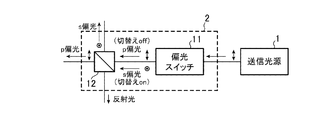
- FIG. 1 is a block diagram showing a polarization switching unit 2 of a laser beam transmitting / receiving apparatus according to Embodiment 2 of the present invention.
- the polarization switch 11 is composed of, for example, a Pockels cell, a car cell, a half-wave plate with a rotating means, or a waveguide-type polarization switch, and the laser light output from the transmission light source 1.
- the polarizer 12 is composed of, for example, a polarization beam splitter, a thin film polarizer, a polaroid (registered trademark / hereinafter, omitted) prism, or a Wollaston prism, etc., depending on the polarization switched by the polarization switch 11.
- the laser beam is output to the reflection mirror 3 or the polarization rotation unit 6.
- the output state is the output state A, and the p-polarized laser light is output to the polarizer 12 without changing the polarization direction of the p-polarized laser light output from the transmission light source 1.
- the polarization switch 11 is turned on, the output state is changed to the output state B, and the polarization direction of the p-polarized laser light output from the transmission light source 1 is rotated by 90 ° to switch the polarization of the laser light to s-polarized light.
- the s-polarized laser light is output to the polarizer 12.
- a Pockels cell (a modulation element constituting an electro-optic modulator) made of lithium niobate (LiNbO 3 ) having a Pockels effect whose refractive index changes in proportion to an applied electric field is used.
- the Pockels cell generates birefringence due to the electro-optic effect when an electric field is applied. At this time, a phase difference occurs in the direction of the fast axis and the slow axis that are orthogonal to the optical axis of the Pockels cell, so that the polarization of the laser light transmitted through the Pockels cell changes.
- the voltage when the polarization direction of the laser light is rotated by 90 ° is called a 1 ⁇ 2 wavelength voltage. Therefore, when a Pockels cell is used as the polarization switch 11, the polarization direction can be switched temporally by switching between the voltage non-application state and the half-wave voltage application state. Since the Pockels cell does not have a movable mechanism and switches polarization by voltage, it has high reliability and can switch polarization at high speed.
- a car cell that is an electro-optic modulator can be used as the polarization switch 11.
- the car cell has a Kerr effect in which the refractive index changes in proportion to the square of the applied electric field. By applying the electric field, the same operation as the Pockels cell can be realized.
- a 1 ⁇ 2 wavelength plate can be used as the polarization switch 11.
- a half-wave plate for example, if a half-wave plate is periodically rotated by attaching a rotation mechanism to the half-wave plate, the same operation as a Pockels cell can be realized. Can do. In this case, although the polarization switching speed is slow, it can be driven with low power consumption. Note that, when a waveguide type polarization switch is used as the polarization switch 11, the output of the laser beam that can be handled becomes small, but the optical system and the drive system of the polarization switch can be made small.
- the polarizer 12 outputs laser light to the reflection mirror 3 or the polarization rotation unit 6 according to the polarization switched by the polarization switch 11.
- a polarizing beam splitter is used as the polarizer 12
- p-polarized light is transmitted and s-polarized light is reflected.
- the polarizer 12 receives the p-polarized laser light from the polarization switch 11 when it is off, the polarizer 12 transmits the p-polarized laser light to the reflection mirror 3 side, and then the s-polarized reflected light output from the reflection mirror 3. Is reflected to the receiving optical system 8 side.
- the polarizer 12 receives the s-polarized laser light from the polarization switch 11, the polarizer 12 reflects the s-polarized laser light toward the polarization rotating unit 6, and then the p-polarized light output from the polarization rotating unit 6. The reflected light is transmitted to the receiving optical system 8 side.
- a polarizer to be used is selected in consideration of power resistance.
- FIG. 3 is an explanatory diagram showing the relationship between the on / off state of the polarization switch 11 and the intensity of each laser beam in the output direction. From FIG. 3, when the polarization switch 11 is off, the laser light is output from the polarizer 12 of the polarization switching unit 2 to the reflection mirror 3, and when the polarization switch 11 is on, from the polarizer 12 of the polarization switching unit 2. It can be seen that the laser light is output to the polarization rotation unit 6. Therefore, the line-of-sight direction can be switched by switching the on / off state of the polarization switch 11.
- the FOM ( Figure of Merit) indicating the figure of merit of the laser beam transmitting / receiving apparatus having one line-of-sight direction is expressed by the following equation (1) according to the laser beam energy E per pulse and the pulse repetition frequency f. ). Therefore, in the laser beam transmitting / receiving apparatus (the first and second embodiments) in which the line-of-sight direction is two directions and the polarization of the laser beam is temporally switched, the FOM per line-of-sight direction is expressed by the following equation (2). expressed.
- the FOM per line-of-sight direction is expressed by the following formula (3).
- the laser light output is distributed in two different directions when the polarization of the laser light is temporally switched as in the first and second embodiments.
- a higher FOM can be obtained. Therefore, when the FOM per line-of-sight direction is made the same, the laser beam transmitter / receiver of Embodiments 1 and 2 is more required for the transmission light source 1 than the laser beam transmitter / receiver described in Patent Document 2.
- the output of the laser beam can be reduced. As a result, the transmission light source 1 can be reduced in size and weight, and the power consumption can be reduced, so that the laser beam transmitting / receiving apparatus can be configured to be small and light.
- the polarization switching unit 2 including the polarization switch 11 and the polarizer 12 is shown to switch the polarization of the laser light in terms of time, but the laser light emitted from the transmission optical systems 5 and 7
- a half-wave plate 13 is used instead of the polarization switch 11 as shown in FIG. Also good.
- the polarizer 12 is output from the transmission light source 1 and is half.
- the laser light transmitted through the wave plate 13 is distributed in two directions (p-polarized laser light is output to the reflection mirror 3 and s-polarized laser light is output to the polarization rotation unit 6).
- the output power of the laser light is divided by half by the polarizer 12 which is a polarization beam splitter, and the output power of each distributed laser light is reduced, but the laser light is simultaneously emitted in two viewing directions. Can do. Therefore, the receiving optical system 8 can receive reflected light in two viewing directions almost simultaneously.
- the distribution ratio of the laser beam distributed by the polarizer 12 can be freely set. Can do.
- the rotation angle of the half-wave plate 13 is switched over time so that the polarization direction is 0 ° or 90 ° with respect to the polarizer 12, it is the same as when the polarization switch 11 is used.
- the polarization of the laser light can be switched over time. In this case, however, a mechanical mechanism for switching the rotation angle of the half-wave plate 13 is required.
- the half-wave plate 13 is used instead of the polarization switch 11.
- 1 is used instead of the polarization switch 11.
- a quarter-wave plate may be used, and the same effect as the half-wave plate 13 is obtained.
- the distribution ratio of the laser light distributed by the polarizer 12 can be freely set.
- an optical rotator that rotates the polarization direction of the laser light may be used, and the same effect as the half-wave plate 13 can be obtained.
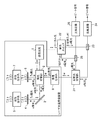
- FIG. 5 is a block diagram showing a laser radar apparatus according to Embodiment 3 of the present invention.
- the laser radar apparatus of FIG. 5 is equipped with the laser beam transmitting / receiving apparatus of FIG.
- the reflected light switching unit 21 is configured by, for example, a polarization coupler or a polarizer, and in a direction corresponding to the polarization of the reflected light (s-polarized reflected light, p-polarized reflected light) received by the receiving optical system 8.
- the reflected light is output.
- the reflected light switching unit 21 transmits the p-polarized reflected light output from the receiving optical system 8, outputs the p-polarized reflected light to the optical multiplexer 23, and outputs the s-polarized light output from the receiving optical system 8.
- the reflected light is reflected and s-polarized reflected light is output to the optical multiplexer 25.
- the reflected light switching unit 21 constitutes reflected light switching means.
- the polarization switch 22 is composed of, for example, a Pockels cell, a car cell, a half-wave plate with a rotating means, or a waveguide-type polarization switch, and is a local equivalent to the laser light output from the transmission light source 1. While temporally switching the polarization of light (light from which the laser light output from the transmission light source 1 is branched), local light is output in a direction corresponding to the polarization. That is, when the polarization switch 22 is off, the polarization direction of the p-polarized local light output from the transmission light source 1 is not changed, and the p-polarized local light is output to the optical multiplexer 23.
- the polarization switch 22 constitutes local light switching means.
- the optical multiplexer 23 includes, for example, a 3 dB coupler, a beam splitter, a partial reflection mirror, and the like, and includes p-polarized reflected light output from the reflected light switching unit 21 and p-polarized local light output from the polarization switch 22. Are combined, and the combined light (the signal of the difference frequency between the reflected light and the local light) is output to the optical detector 24.
- the optical detector 24 is composed of, for example, a photodiode or a balanced receiver, converts the combined light output from the optical multiplexer 23 into an electrical signal, and outputs a beat signal that is the electrical signal.
- the optical multiplexer 23 and the optical detector 24 constitute a first heterodyne detector.
- the optical multiplexer 25 includes, for example, a 3 dB coupler, a beam splitter, a partial reflection mirror, and the like.
- the optical multiplexer 25 is an s-polarized reflected light output from the reflected light switching unit 21 and an s output from the polarization switch 22.
- the polarized local light is optically combined, and the combined light (a signal having a difference frequency between the reflected light and the local light) is output to the optical detector 26.
- the optical detector 26 is composed of, for example, a photodiode or a balanced receiver, converts the combined light output from the optical combiner 25 into an electrical signal, and outputs a beat signal that is the electrical signal.
- the optical multiplexer 25 and the optical detector 26 constitute a second heterodyne detector.
- the reflected light switching unit 21, the polarization switch 22, the optical multiplexers 23 and 25, and the optical detectors 24 and 26 constitute a heterodyne detection unit.
- the reception optical system 8 receives reflected light (s-polarized reflected light, p-polarized reflected light)
- the reflected light switching unit 21 receives the reflected light (s-polarized light).
- the output destination of the reflected light is temporally switched according to the polarization of the reflected light (p-polarized reflected light). That is, when receiving the p-polarized reflected light from the receiving optical system 8, the reflected light switching unit 21 transmits the p-polarized reflected light and outputs the p-polarized reflected light to the optical multiplexer 23.
- the s-polarized reflected light is received from the receiving optical system 8
- the s-polarized reflected light is reflected and the s-polarized reflected light is output to the optical multiplexer 25. Since the polarization direction of the reflected light input from the reception optical system 8 to the reflected light switching unit 21 is switched over time by switching the polarization switch 11 on and off, the reflected light output from the reflected light switching unit 21 Will switch the output destination in time.
- the polarization switch 22 is turned on in a time period in which the polarization switching unit 2 outputs p-polarized laser light and obtains s-polarized reflected light, and the p-polarized local light (p-polarized laser) is transmitted from the transmission light source 1. Light), the polarization direction of the p-polarized local light is rotated by 90 ° to switch the polarization of the local light to s-polarized light, and the s-polarized local light is transmitted to the optical multiplexer 25. Output.
- the polarization switch 22 is turned off in a time zone in which the polarization switching unit 2 outputs the s-polarized laser light and obtains the p-polarized reflected light, and receives the p-polarized local light from the transmission light source 1.
- the p-polarized local light is output to the optical multiplexer 23 without changing the polarization direction of the p-polarized local light.
- the polarization switching unit 2 and the polarization switch 22 may synchronize the operation timing. Further, either one may have a delay time. By synchronizing the operation timing, heterodyne detection can be performed efficiently. Further, by providing a delay time, it is possible to perform heterodyne detection except for a transient state when the polarization switching unit 2 switches the polarization.
- the optical multiplexer 23 optically combines the p-polarized reflected light output from the reflected light switching unit 21 and the p-polarized local light output from the polarization switch 22, and the combined light (reflected light and local light).
- the optical difference frequency signal) is output to the optical detector 24.
- the optical detector 24 converts the combined light into an electrical signal and outputs a beat signal that is the electrical signal.
- the optical multiplexer 25 optically combines the s-polarized reflected light output from the reflected light switching unit 21 and the s-polarized local light output from the polarization switch 22, and the combined light (reflected light and local light).
- the signal of the difference frequency of light is output to the optical detector 26.
- the optical detector 26 Upon receiving the combined light from the optical combiner 25, the optical detector 26 converts the combined light into an electrical signal and outputs a beat signal that is the electrical signal.
- the beat signals output from the optical detectors 24 and 26 are input to a signal processor (not shown), and the signal processor analyzes the frequency component of the beat signal to calculate the moving speed (wind speed) of the target. It can. Since the laser beam is emitted in the two line-of-sight directions, observation in the two line-of-sight directions is possible, and the wind direction of the surface including the two directions can be measured. Further, the distance to the target can be calculated from the time from when the laser light is emitted until the reflected light is received. Since the laser beam is emitted in the two line-of-sight directions, the observation in the two line-of-sight directions is possible, and the wind direction in the plane including the two directions can be calculated by processing such as computation.
- the polarization switching unit 2 that outputs the laser light in the direction corresponding to the polarization while temporally switching the polarization of the laser light output from the transmission light source 1.
- the laser beam can be transmitted in the two line-of-sight directions without mechanically scanning the laser beam without reducing the power.
- the polarization switch 22 switches the polarization of the local light branched from the laser light output from the transmission light source 1 while temporally switching the polarization of the local light in the direction corresponding to the polarization. Since it is configured to output, it is not necessary to mount a light source for local light.
- the polarization of the local light is temporally switched by the polarization switch 22, the local light is output in a direction corresponding to the polarization, and the polarization of the reflected light output from the reception optical system 8. Since it is configured to match the direction, heterodyne detection can be performed efficiently. Moreover, since the output of the local light requested
- a polarization coupler is used as the reflected light switching unit 21
- a waveguide type polarization switch is used as the polarization switch 22
- optical fiber parts are used as 3 dB couplers as the optical multiplexers 23 and 25.
- the receiving system of the laser radar apparatus can be assembled by connecting the optical fiber, the alignment of the laser beam is not required, and the apparatus configuration can be made small and highly stable.
- the apparatus can be configured more easily by using polarization maintaining optical fiber components as these components.
- a balanced receiver is used as the optical detectors 24 and 26, it is possible to reduce the influence of noise and perform highly sensitive detection.
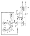
- FIG. 6 is a block diagram showing a laser radar apparatus according to Embodiment 4 of the present invention.
- the local light branching unit 27 includes, for example, a polarization coupler, a polarizing beam splitter, a thin film polarizer, a polaroid plate, or a polarizer such as a Glan laser prism or a Wollaston prism, and the local light output from the transmission light source 1.
- the light (light branched from the laser light) is branched in two directions. If a polarization coupler is used as the local light branching unit 27, it can be handled by an optical fiber.
- the local light branching unit 27 constitutes a local light branching unit.
- the polarization switch 22 switches on / off with time, outputs p-polarized local light to the optical multiplexer 23 when it is off, and s-polarized local light when it is on. Is output to the optical multiplexer 25, but when the local light branching unit 27 receives local light from the transmission light source 1 as in the fourth embodiment shown in FIG. 6, the local light is branched into two. Thus, the p-polarized local light may be output to the optical multiplexer 23, and at the same time, the s-polarized local light may be output to the optical multiplexer 25.
- the local light branching unit 27 When a polarization coupler is used as the local light branching unit 27, if the polarization of the local light output from the transmission light source 1 enters the polarization coupler so as to be half of the p-polarized light and the s-polarized light, the power of the local light Can be halved.
- the local light branching unit 27 instead of the polarization switch 22, the cost can be reduced and the reliability can be improved, but the output power of the local light is required twice.
- FIG. 7 is a block diagram showing a laser radar apparatus according to Embodiment 5 of the present invention.
- the polarization switch 28 is composed of, for example, a Pockels cell, a car cell, a half-wave plate with a rotating means, or a waveguide-type polarization switch, and the like, and p-polarized local light output from the transmission light source 1 ( This is a polarization switching device that temporally switches the polarization of light branched from p-polarized laser light.
- the polarization switch 28 alternately outputs p-polarized local light and s-polarized local light in the same manner as the polarization switch 22 of FIG. 5, but the polarization switch 28 differs from the polarization switch 22 of FIG. Are output to the same optical multiplexer 29 without switching the output destinations of the local light and the s-polarized local light.
- the polarization switch 28 constitutes local light switching means.
- the optical multiplexer 29 includes, for example, a 3 dB coupler, a beam splitter, a partial reflection mirror, and the like.
- the optical multiplexer 29 receives the p-polarized reflected light output from the receiving optical system 8 and the p-polarized local light output from the polarization switch 28. Optically combined, the combined light is output to the optical detector 30, and the s-polarized reflected light output from the receiving optical system 8 and the s-polarized local light output from the polarization switch 28 are optically generated. Are combined, and the combined light is output to the optical detector 30.
- the optical detector 30 is composed of, for example, a photodiode or a balanced receiver, converts the combined light output from the optical multiplexer 29 into an electrical signal, and outputs a beat signal that is the electrical signal.
- the optical combiner 29 and the optical detector 30 constitute a heterodyne detector.
- the polarization switch 28, the optical multiplexer 29, and the optical detector 30 constitute a heterodyne detection means.
- the reception optical system 8 receives the s-polarized reflected light that is output from the reflection mirror 3 and then reflected by the polarization switching unit 2. Further, after being output from the polarization rotation unit 6, the p-polarized reflected light transmitted through the polarization switching unit 2 is received. That is, the polarization direction of the reflected light received by the receiving optical system 8 is switched over time. The reception optical system 8 outputs the received reflected light to the optical multiplexer 29.
- the polarization switch 28 When the polarization switching unit 2 outputs p-polarized laser light and obtains s-polarized reflected light, the polarization switch 28 is turned on. When the polarization switch 28 receives p-polarized local light from the transmission light source 1, the polarization switch 28 receives p-polarized light. By rotating the polarization direction of the polarized local light by 90 °, the polarization of the local light is switched to s-polarized light, and the s-polarized local light is output to the optical multiplexer 29.
- the polarization switch 28 is turned off in a time period in which the polarization switching unit 2 outputs the s-polarized laser light and obtains the p-polarized reflected light, and receives the p-polarized local light from the transmission light source 1.
- the p-polarized local light is output to the optical multiplexer 29 without changing the polarization direction of the p-polarized local light.
- the reflected light of s-polarized light is output from the receiving optical system 8 to the optical multiplexer 29.
- s-polarized local light is output from the polarization switch 28 to the optical multiplexer 29.
- the p-polarized local light is output from the polarization switch 28 to the optical multiplexer 29.
- the optical multiplexer 29 optically combines the p-polarized reflected light output from the receiving optical system 8 and the p-polarized local light output from the polarization switch 28, and the combined light is used as the optical detector 30. Output to.
- the optical multiplexer 29 optically combines the s-polarized reflected light output from the receiving optical system 8 and the s-polarized local light output from the polarization switch 28, and optically detects the combined light.
- the optical detector 30 converts the combined light into an electrical signal and outputs a beat signal that is the electrical signal.
- the same effects as those of the third and fourth embodiments can be obtained, but the reflected light switching unit 21 is unnecessary, and the apparatus can be configured with one heterodyne detector. Therefore, it is possible to construct a device that is small and inexpensive.
- the polarization switch 28 may be arranged on the path from the reception optical system 8 to the optical multiplexer 29 to switch the polarization direction of the received reflected light. However, a loss occurs with respect to the reception light. When there is a margin in the power of local light, it is desirable to arrange it on the path of local light.
- the reception optical system 8 receives the s-polarized reflected light and the p-polarized reflected light almost simultaneously.
- a polarization branching unit 31 p-polarized reflection
- a polarization branching unit that outputs light to the optical multiplexer 23 and outputs reflected light of s-polarized light to the optical multiplexer 23 may be provided. Further, in the polarization switch 22, the s-polarized local light and the p-polarized local light are simultaneously output using the half-wave plate 13 or the quarter-wave plate, so that the reflected light in the two viewing directions can be obtained. Heterodyne detection can be performed at the same time, and observation in two gaze directions can be performed simultaneously.
- the laser beam transmitter / receiver and the laser radar device according to the present invention are suitable for devices that require observation in two viewing directions.
Landscapes
- Engineering & Computer Science (AREA)
- Physics & Mathematics (AREA)
- Computer Networks & Wireless Communication (AREA)
- General Physics & Mathematics (AREA)
- Radar, Positioning & Navigation (AREA)
- Remote Sensing (AREA)
- Electromagnetism (AREA)
- Optical Radar Systems And Details Thereof (AREA)
Abstract
Description
(1)レーザ光を出力するレーザ光源
(2)レーザ光源から出力されたレーザ光を透過する偏光ビームスプリッタ
(3)偏光ビームスプリッタを透過したレーザ光を透過する1/4波長板
(4)ターゲットに反射して戻ってきたレーザ光の反射光を受光する受光器
レーザ光の反射光が1/4波長板を透過することで、レーザ光源から出力された時点のレーザ光と比べて偏光が90°回転する。そのため、レーザ光の反射光は、偏光ビームスプリッタで反射されて、レーザ光源と異なる方向に配置されている受光器によって受光される。
なお、スキャナ光学素子はガルバナミラーによって構成されており、スキャナ制御装置はガルバナミラーを駆動する電動機制御装置を搭載している。
偏光ビームスプリッタは、レーザ光源から出力されたレーザ光におけるp偏光とs偏光を分岐するものであり、レーザ光を2方向に分岐することができる。
偏光ビームスプリッタは、故障する可能性がある可動部を備えておらず、機械的な制御を行うことなく、レーザ光を2方向に分岐することができる。
また、偏光ビームスプリッタを用いて、レーザ光源から出力されたレーザ光を2分岐する場合(特許文献2)、可動部がないため、装置の信頼性を高めることができるが、レーザ光を偏光によって2分岐するものであるため、1パルス当りのエネルギーが半分になる。そのため、送受信するレーザ光のパワーが低下して、観測精度が劣化してしまうことがある課題があった。
図1はこの発明の実施の形態1によるレーザ光送受信装置を示す構成図である。
図1において、送信光源1は直線偏光のレーザ光を出力する光源である。図1のレーザ光送受信装置が、風計測用ドップラーライダとして用いられる場合、単一周波数のレーザ光を出力する。また、図1のレーザ光送受信装置が、遠距離に存在しているターゲット(観測対象)を観測するレーザレーダ装置の一部を構成する場合、高ピークパルスのレーザ光又は連続波であるCW(Continuous Wave)光を出力する。
なお、レーザ光の波長は、目への安全性を考慮して、1.5μm~1.7μmのアイセーフ波長を使用する場合が多い。
この実施の形態1では、送信光源1が直線偏光のレーザ光を出力する例を説明するが、円偏光のレーザ光を出力するものであってもよい。
即ち、偏光切替部2は送信光源1からp偏光のレーザ光が出力されると、p偏光のレーザ光を反射ミラー3側に透過させる出力状態Aと、送信光源1から出力されたp偏光のレーザ光の偏光方向を90°回転させることで、そのレーザ光の偏光をs偏光に切り替えて、s偏光のレーザ光を偏光回転部6側に反射させる出力状態Bとが時間的に切り替わる光学部品である。なお、偏光切替部2は偏光切替手段を構成している。
この実施の形態1では、送信光源1がp偏光のレーザ光を出力する例を説明するが、送信光源1がs偏光のレーザ光を出力するものであってもよい。
この場合、偏光切替部2は、s偏光のレーザ光の偏光方向を90°回転させることで、そのレーザ光の偏光をp偏光に切り替えて、p偏光のレーザ光を反射ミラー3側に透過させる出力状態Aと、送信光源1から出力されたs偏光のレーザ光を偏光回転部6側に反射させる出力状態Bとが時間的に切り替わる光学部品となる。
偏光回転部4は、例えば、1/4波長板、旋光子、ファラデー回転子、あるいは、ポッケルスセルなどで構成される。図1のレーザ光送受信装置では1/4波長板を用いているものとすると、偏光回転部4は反射ミラー3から出力された直線偏光であるp偏光のレーザ光を円偏光のレーザ光に変換して、円偏光のレーザ光を送信光学系5に出力する一方、送信光学系5から出力された円偏光の反射光(空間に存在しているターゲットに反射されて戻ってきたレーザ光の反射光)を直線偏光であるs偏光のレーザ光に変換し、s偏光のレーザ光を反射ミラー3に出力する。即ち、偏光回転部4は、反射ミラー3から偏光回転部4へと出力されるレーザの偏光方向に対して、送信光学系5から偏光回転部4を通過して反射ミラー3へと出力される反射光の偏光方向を90°回転させる光学部品である。
送信光学系5はレーザ光である送信光のビーム径の拡大や、ビームのコリメート化を図るために搭載されているが、送信光のビームを変更する必要がない場合は、送信光学系5を搭載する必要がない。
反射ミラー3から偏光切替部2に出力されたs偏光の反射光は、偏光切替部2で反射されて受信光学系8に出力される。
なお、反射ミラー3、偏光回転部4及び送信光学系5から第1の送受信光学系が構成されている。
図1のレーザ光送受信装置では偏光回転部6として1/4波長板を用いているものとすると、偏光回転部6は偏光切替部2から出力された直線偏光であるs偏光のレーザ光を円偏光のレーザ光に変換して、円偏光のレーザ光を送信光学系7に出力する一方、送信光学系7から出力された円偏光の反射光(空間に存在しているターゲットに反射されて戻ってきたレーザ光の反射光)を直線偏光であるp偏光のレーザ光に変換し、p偏光のレーザ光を偏光切替部2に出力する光学部品である。
送信光学系7は例えばレンズやウィンドウなどから構成されており、偏光回転部6から出力された円偏光のレーザ光を空間に放射する一方、空間に存在しているターゲットに反射されて戻ってきた前記レーザ光の反射光(反射光は、進行方向に対して、送信光(空間に放射したレーザ光)と逆回転の円偏光になる)を受信し、円偏光の反射光を偏光回転部6に出力する。
送信光学系7はレーザ光である送信光のビーム径の拡大や、ビームのコリメート化を図るために搭載されているが、送信光のビームを変更する必要がない場合は、送信光学系7を搭載する必要がない。
偏光回転部6から偏光切替部2に出力されたp偏光の反射光は、偏光切替部2を透過して受信光学系8に出力される。
なお、偏光回転部6及び送信光学系7から第2の送受信光学系が構成されている。
受信光学系8は、図示せぬ受光素子と結合される場合、その受光素子の受信開口内に対して、偏光切替部2から出力された反射光を損失なく入射させるために、その反射光を受光素子の受信開口内に集光させる機能を備えている。
また、受信光学系8は、図示せぬ光ファイバーと結合される場合、偏光切替部2から出力された反射光を集光させ、光ファイバーのコアに結合させる機能を備えている。
送信光源1は、直線偏光であるp偏光のレーザ光を出力する。
偏光切替部2は、送信光源1からp偏光のレーザ光が出力されると、そのレーザ光の偏光を時間的に切り替えながら、その偏光に対応する方向にレーザ光を出力する。
即ち、偏光切替部2は、p偏光のレーザ光を反射ミラー3側に透過させる出力状態Aと、送信光源1から出力されたp偏光のレーザ光の偏光方向を90°回転させることで、そのレーザ光の偏光をs偏光に切り替えて、s偏光のレーザ光を偏光回転部6側に反射させる出力状態Bとを有し、その出力状態Aと出力状態Bを時間的に切り替えることで、2視線方向のレーザ光の出力を実現している。
偏光回転部4は、反射ミラー3からp偏光のレーザ光を受けると、そのレーザ光の透過時に、p偏光(直線偏光)のレーザ光を円偏光のレーザ光に変換して、円偏光のレーザ光を送信光学系5に出力する。
送信光学系5は、偏光回転部4から円偏光のレーザ光を受けると、そのレーザ光を送信光として空間に放射する。
その後、空間に存在しているターゲットに反射されて戻ってきたレーザ光の一部(反射光)は送信光学系5が受信し、送信光学系5が反射光を偏光回転部4に出力する。なお、反射光は、進行方向に対して、送信光と逆回転の円偏光になっている。
反射ミラー3は、偏光回転部4からs偏光の反射光を受けると、その反射光を偏光切替部2側に反射させる。
反射ミラー3から偏光切替部2に出力されたs偏光の反射光は、偏光切替部2で反射されて受信光学系8に出力される。
送信光学系7は、偏光回転部6から円偏光のレーザ光を受けると、そのレーザ光を送信光として空間に放射する。
その後、空間に存在しているターゲットに反射されて戻ってきたレーザ光の一部(反射光)は送信光学系7が受信し、送信光学系7が反射光を偏光回転部6に出力する。なお、反射光は、進行方向に対して、送信光と逆回転の円偏光になっている。
偏光回転部6から偏光切替部2に出力されたp偏光の反射光は、偏光切替部2を透過して受信光学系8に出力される。
受信光学系8は、反射ミラー3から出力されたのち、偏光切替部2で反射されたs偏光の反射光を受信するとともに、偏光回転部6から出力されたのち、偏光切替部2を透過したp偏光の反射光を受信する。
即ち、受信光学系8は、s偏光の反射光と、p偏光の反射光とを直交偏光で受信している。
また、この実施の形態1では、2視線方向にレーザ光を放射しているので、2視線方向の観測が可能になり、2方向を含む面の風向きを測定することができる。また、レーザ光を放射してから反射光を受信するまでの時間から、ターゲットまでの距離を算出することができる。
即ち、偏光に対応する方向にレーザ光を出力する偏光切替部2を設けることで、送信光源1や受信光学系8を複数台搭載することなく、2視線方向の観測が可能になり、装置の小型化や軽量化を図ることができる。
また、2視線方向の観測を行うために、レーザ光を機械的に走査する走査機構を備える必要がないため、装置の小型化を図ることができるとともに、信頼性が高い装置(振動や衝撃に対する耐性が高い装置)が得られる。
上記実施の形態1では、送信光源1から出力されたレーザ光の偏光を時間的に切り替えながら、その偏光に対応する方向にレーザ光を出力する偏光切替部2を設けているものを示したが、この実施の形態2では、偏光切替部2の具体的な構成例を説明する。
図2はこの発明の実施の形態2によるレーザ光送受信装置の偏光切替部2を示す構成図である。
図2において、偏光スイッチ11は例えばポッケルスセル、カーセル、回転手段が付いている1/2波長板、あるいは、導波路型の偏光スイッチなどで構成されており、送信光源1から出力されたレーザ光の偏光を時間的に切り替える偏光切替器である。
偏光子12は例えば偏光ビームスプリッタ、薄膜偏光子、ポラロイド(登録商標/以下、記載を省略する)プリズム、あるいは、ウォラストンプリズムなどで構成されており、偏光スイッチ11により切り替えられた偏光に応じて、レーザ光を反射ミラー3又は偏光回転部6に出力する。
偏光スイッチ11は、オフのときには出力状態が出力状態Aになり、送信光源1から出力されたp偏光のレーザ光の偏光方向を変えずに、p偏光のレーザ光を偏光子12に出力する。
偏光スイッチ11は、オンのときには出力状態が出力状態Bになり、送信光源1から出力されたp偏光のレーザ光の偏光方向を90°回転させることで、そのレーザ光の偏光をs偏光に切り替えて、s偏光のレーザ光を偏光子12に出力する。
ポッケルスセルは、電界を印加することで電気光学効果によって複屈折が発生する。このとき、ポッケルスセルの光学軸と直交する軸である速軸と遅軸の方向に位相差が生じるため、ポッケルスセルを透過するレーザ光の偏光が変化する。レーザ光の偏光方向が90°回転するときの電圧は1/2波長電圧と呼ばれる。
したがって、偏光スイッチ11として、ポッケルスセルを用いる場合、電圧無印加状態と、1/2波長電圧印加状態とを切り替えることで、偏光方向を時間的に切り替えることができる。ポッケルスセルは、可動機構を持たずに、電圧によって偏光を切り替えるものであるため、信頼性が高く、また、高速に偏光を切り替えることができる。
また、偏光スイッチ11として、1/2波長板を用いることができる。1/2波長板を用いる場合、例えば、1/2波長板に対して回転機構を付けることで、1/2波長板を周期的に回転させれば、ポッケルスセルと同様の動作を実現することができる。この場合、偏光の切替速度が遅くなるが、低消費電力で駆動することができる。
なお、偏光スイッチ11として、導波路型の偏光スイッチを用いる場合、取り扱えるレーザ光の出力が小さくなるが、光学系や偏光スイッチの駆動系を小さくすることができる。
偏光子12として、例えば、偏光ビームスプリッタを用いる場合、入射光に対して水平に反射するように設置すると、p偏光は透過して、s偏光は反射するようになる。
したがって、偏光子12は、偏光スイッチ11からオフ時にp偏光のレーザ光を受けると、p偏光のレーザ光を反射ミラー3側に透過させ、その後、反射ミラー3から出力されたs偏光の反射光を受信光学系8側に反射される。
また、偏光子12は、偏光スイッチ11からオン時にs偏光のレーザ光を受けると、s偏光のレーザ光を偏光回転部6側に反射させ、その後、偏光回転部6から出力されたp偏光の反射光を受信光学系8側に透過させる。
なお、遠方に存在しているターゲットを観測するために高出力のレーザ光を使用する場合には、耐パワー性を考慮して使用する偏光子を選択する。
図3より、偏光スイッチ11がオフのときは、偏光切替部2の偏光子12からレーザ光が反射ミラー3に出力され、偏光スイッチ11がオンのときは、偏光切替部2の偏光子12からレーザ光が偏光回転部6に出力されることが分かる。
したがって、偏光スイッチ11のオン/オフ状態を切り替えれば、視線方向を切り替えることができる。


したがって、1視線方向当りのFOMを同じにする場合、特許文献2に記載されているレーザ光送受信装置より、実施の形態1,2のレーザ光送受信装置の方が、送信光源1に要求されるレーザ光の出力を小さくすることができる。これにより、送信光源1の小型化および軽量化を図ることができるとともに、低消費電力化を図ることができ、レーザ光送受信装置を小型、軽量に構成することができる。
例えば、偏光ビームスプリッタである偏光子12に対して、偏光方向が45°になるように1/2波長板13を回転させると、偏光子12が、送信光源1から出力されて、1/2波長板13を透過してきたレーザ光を2方向に分配する(p偏光のレーザ光を反射ミラー3に出力して、s偏光のレーザ光を偏光回転部6に出力する)。
このとき、偏光ビームスプリッタである偏光子12によってレーザ光の出力パワーが半分ずつに分けられて、分配された各レーザ光の出力パワーが小さくなるが、2視線方向にレーザ光を同時に放射することができる。
したがって、受信光学系8では、2視線方向の反射光をほぼ同時に受信することができる。
なお、偏光子12に対して偏光方向が0°または90°となるように、1/2波長板13の回転角度を時間的に切り替えるようにした場合には、偏光スイッチ11を用いる場合と同様に、レーザ光の偏光を時間的に切り替えることができる。
ただし、この場合、1/2波長板13の回転角度を切り替える機械的な機構が必要になる。
また、偏光スイッチ11の代わりに、レーザ光の偏光方向を回転させる旋光子を用いるもようにしてもよく、1/2波長板13と同様の効果が得られる。
図5はこの発明の実施の形態3によるレーザレーダ装置を示す構成図であり、図5のレーザレーダ装置は図1のレーザ光送受信装置を搭載している。図5において、図1と同一符号は同一または相当部分を示すので説明を省略する。
反射光切替部21は例えば偏波カプラあるいは偏光子などで構成されており、受信光学系8により受信された反射光(s偏光の反射光、p偏光の反射光)の偏光に対応する方向に、その反射光を出力する。
即ち、反射光切替部21は受信光学系8から出力されたp偏光の反射光を透過して、p偏光の反射光を光合波器23に出力し、受信光学系8から出力されたs偏光の反射光を反射して、s偏光の反射光を光合波器25に出力する。なお、反射光切替部21は反射光切替手段を構成している。
即ち、偏光スイッチ22はオフのときには、送信光源1から出力されたp偏光のローカル光の偏光方向を変えずに、p偏光のローカル光を光合波器23に出力し、オンのときには、送信光源1から出力されたp偏光のローカル光の偏光方向を90°回転させることで、そのローカル光の偏光をs偏光に切り替えて、s偏光のローカル光を光合波器25に出力する。なお、偏光スイッチ22はローカル光切替手段を構成している。
光検波器24は例えばフォトダイオード、あるいは、バランスドレシーバなどで構成されており、光合波器23から出力された合波光を電気信号に変換し、その電気信号であるビート信号を出力する。
なお、光合波器23及び光検波器24から第1のヘテロダイン検波器が構成されている。
光検波器26は例えばフォトダイオード、あるいは、バランスドレシーバなどで構成されており、光合波器25から出力された合波光を電気信号に変換し、その電気信号であるビート信号を出力する。
なお、光合波器25及び光検波器26から第2のヘテロダイン検波器が構成されている。
また、反射光切替部21、偏光スイッチ22、光合波器23,25及び光検波器24,26からヘテロダイン検波手段が構成されている。
反射光切替部21は、上記実施の形態1,2と同様にして、受信光学系8が反射光(s偏光の反射光、p偏光の反射光)を受信すると、その反射光(s偏光の反射光、p偏光の反射光)の偏光によって、その反射光の出力先を時間的に切り替える。
即ち、反射光切替部21は、受信光学系8からp偏光の反射光を受けると、p偏光の反射光を透過して、p偏光の反射光を光合波器23に出力する。
一方、受信光学系8からs偏光の反射光を受けると、s偏光の反射光を反射して、s偏光の反射光を光合波器25に出力する。
偏光スイッチ11のオン、オフの切り替えにより、受信光学系8から反射光切替部21に入力される反射光は偏光方向が時間的に切り替わっているため、反射光切替部21から出力される反射光は出力先が時間的に切り替わることとなる。
また、偏光スイッチ22は、偏光切替部2がs偏光のレーザ光を出力してp偏光の反射光を得ている時間帯ではオフ状態になり、送信光源1からp偏光のローカル光を受けると、p偏光のローカル光の偏光方向を変えずに、p偏光のローカル光を光合波器23に出力する。
なお、偏光切替部2と偏光スイッチ22は、動作タイミングを同期させても良い。また、どちらか一方に遅延時間を持たせるようにしても良い。動作タイミングを同期させることで、効率良くヘテロダイン検波を行うことができる。また、遅延時間を持たせることで、偏光切替部2で偏光を切り替える際の過渡状態を除いてヘテロダイン検波を行うようにすることができる。
光検波器24は、光合波器23から合波光を受けると、その合波光を電気信号に変換し、その電気信号であるビート信号を出力する。
光合波器25は、反射光切替部21から出力されたs偏光の反射光と偏光スイッチ22から出力されたs偏光のローカル光とを光学的に合波し、その合波光(反射光とローカル光の差周波数の信号)を光検波器26に出力する。
光検波器26は、光合波器25から合波光を受けると、その合波光を電気信号に変換し、その電気信号であるビート信号を出力する。
また、レーザ光を放射してから反射光を受信するまでの時間から、ターゲットまでの距離を算出することができる。2視線方向にレーザ光を放射しているので、2視線方向の観測が可能になり、演算等の処理により2方向を含む面内の風向きを算出することができる。
また、この実施の形態3によれば、偏光スイッチ22が、送信光源1から出力されたレーザ光が分岐されたローカル光の偏光を時間的に切り替えながら、その偏光に対応する方向にローカル光を出力するように構成したので、ローカル光用の光源を搭載する必要がない。このため、装置の小型化を図ることができるとともに、省電力化を図ることができる効果を奏する。
また、この実施の形態3によれば、偏光スイッチ22によりローカル光の偏光を時間的に切り替え、その偏光に対応する方向にローカル光を出力させ、受信光学系8から出力される反射光の偏光方向に合わせるように構成したため、効率良くヘテロダイン検波を行うことができる。また、送信光源1に要求されるローカル光の出力を小さくすることができるため、装置の小型化を図ることができるとともに、省電力化を図ることができる効果を奏する。
また、光検波器24,26としてバランスドレシーバを用いた場合には、雑音の影響を低減して高感度な検出を行うことができる。
図6はこの発明の実施の形態4によるレーザレーダ装置を示す構成図であり、図6において、図5と同一符号は同一または相当部分を示すので説明を省略する。
ローカル光分岐部27は例えば偏波カプラ、偏光ビームスプリッタ、薄膜偏光子、ポラロイド板、あるいは、グランレーザプリズムやウォラストンプリズム等の偏光子などで構成されており、送信光源1から出力されたローカル光(レーザ光から分岐された光)を2方向に分岐する。ローカル光分岐部27として偏光カプラを用いれば、光ファイバーで取り扱うことができる。なお、ローカル光分岐部27はローカル光分岐手段を構成している。
ローカル光分岐部27として偏波カプラを用いる場合、送信光源1から出力されたローカル光の偏光が、p偏光とs偏光の半分ずつになるように偏波カプラに入射すれば、ローカル光のパワーを半々にすることができる。
偏光スイッチ22の代わりに、ローカル光分岐部27を使用することで、低コスト化と信頼性の向上を図ることができるが、ローカル光の出力パワーが2倍必要になる。
図7はこの発明の実施の形態5によるレーザレーダ装置を示す構成図であり、図7において、図5と同一符号は同一または相当部分を示すので説明を省略する。
偏光スイッチ28は例えばポッケルスセル、カーセル、回転手段が付いている1/2波長板、あるいは、導波路型の偏光スイッチなどで構成されており、送信光源1から出力されたp偏光のローカル光(p偏光のレーザ光から分岐された光)の偏光を時間的に切り替える偏光切替器である。
これにより、偏光スイッチ28は図5の偏光スイッチ22と同様に、p偏光のローカル光とs偏光のローカル光を交互に出力するが、偏光スイッチ28は図5の偏光スイッチ22と異なり、p偏光のローカル光とs偏光のローカル光の出力先を切り替えずに、同じ光合波器29に出力している。なお、偏光スイッチ28はローカル光切替手段を構成している。
光検波器30は例えばフォトダイオード、あるいは、バランスドレシーバなどで構成されており、光合波器29から出力された合波光を電気信号に変換し、その電気信号であるビート信号を出力する。
なお、光合波器29及び光検波器30からヘテロダイン検波器が構成されている。
また、偏光スイッチ28、光合波器29及び光検波器30からヘテロダイン検波手段が構成されている。
受信光学系8は、上記実施の形態1~4と同様に、反射ミラー3から出力されたのち、偏光切替部2で反射されたs偏光の反射光を受信する。また、偏光回転部6から出力されたのち、偏光切替部2を透過したp偏光の反射光を受信する。即ち、受信光学系8で受信される反射光は、偏光方向が時間的に切り替わっている。
受信光学系8は、受信した反射光を光合波器29に出力する。
また、偏光スイッチ28は、偏光切替部2がs偏光のレーザ光を出力してp偏光の反射光を得ている時間帯ではオフ状態になり、送信光源1からp偏光のローカル光を受けると、p偏光のローカル光の偏光方向を変えずに、p偏光のローカル光を光合波器29に出力する。
また、光合波器29は、受信光学系8から出力されたs偏光の反射光と偏光スイッチ28から出力されたs偏光のローカル光とを光学的に合波して、その合波光を光検波器30に出力する。
光検波器30は、光合波器29から合波光を受けると、その合波光を電気信号に変換し、その電気信号であるビート信号を出力する。
なお、偏光スイッチ28は、受信光学系8から光合波器29までの経路上に配置し、受信した反射光の偏光方向を切り替えるようにしても良いが、受信光に対して損失が発生するため、ローカル光のパワーに余裕がある場合にはローカル光の経路上に配置することが望ましい。
この場合、図8に示すように、反射光切替部21の代わりに、受信光学系8により受信されたs偏光の反射光とp偏光の反射光を分岐する偏光分岐部31(p偏光の反射光を光合波器23に出力し、s偏光の反射光を光合波器23に出力する偏光分岐部)を備えるようにすればよい。
さらには、偏光スイッチ22においても、1/2波長板13や1/4波長板などを用いてs偏光のローカル光とp偏光のローカル光を同時に出力させることにより、2視線方向の反射光を同時にヘテロダイン検波することができ、2視線方向の観測を同時に行うことができる。
Claims (7)
- レーザ光を出力する光源と、
前記光源から出力されたレーザ光の偏光を時間的に切り替えながら、前記偏光に対応する方向に前記レーザ光を出力する偏光切替手段と、
前記偏光切替手段から出力されたレーザ光を空間に放射し、空間に存在している観測対象に反射された前記レーザ光の反射光を受信する第1の送受信光学系と、
前記第1の送受信光学系と異なる方向に配置されており、前記偏光切替手段から出力されたレーザ光を空間に放射し、空間に存在している観測対象に反射された前記レーザ光の反射光を受信する第2の送受信光学系と、
前記第1の送受信光学系により受信された反射光を受信するとともに、前記第2の送受信光学系により受信された反射光を受信する受信光学系と
を備えたレーザ光送受信装置。 - 前記偏光切替手段は、
前記光源から出力されたレーザ光の偏光を時間的に切り替える偏光切替器と、
前記偏光切替器により切り替えられた偏光に応じて、前記レーザ光を前記第1の送受信光学系又は前記第2の送受信光学系に出力する偏光子とから構成されていることを特徴とする請求項1記載のレーザ光送受信装置。 - 前記偏光子は、前記第1及び第2の送受信光学系により受信された反射光を前記受信光学系が配置されている方向に反射させることを特徴とする請求項2記載のレーザ光送受信装置。
- レーザ光を出力する光源と、
前記光源から出力されたレーザ光の偏光を時間的に切り替えながら、前記偏光に対応する方向に前記レーザ光を出力する偏光切替手段と、
前記偏光切替手段から出力されたレーザ光を空間に放射し、空間に存在している観測対象に反射された前記レーザ光の反射光を受信する第1の送受信光学系と、
前記第1の送受信光学系と異なる方向に配置されており、前記偏光切替手段から出力されたレーザ光を空間に放射し、空間に存在している観測対象に反射された前記レーザ光の反射光を受信する第2の送受信光学系と、
前記第1の送受信光学系により受信された反射光を受信するとともに、前記第2の送受信光学系により受信された反射光を受信する受信光学系と、
前記受信光学系により受信された反射光と、前記光源から出力されたレーザ光に相当するローカル光とを合波してビート信号を得るヘテロダイン検波手段と
を備えたレーザレーダ装置。 - 前記ヘテロダイン検波手段は、
前記受信光学系により受信された反射光の偏光に対応する方向に、前記反射光を出力する反射光切替手段と、
前記光源から出力されたレーザ光に相当するローカル光の偏光を時間的に切り替えながら、前記偏光に対応する方向に前記ローカル光を出力するローカル光切替手段と、
前記反射光切替手段から出力された反射光と前記ローカル光切替手段から出力されたローカル光とを合波してビート信号を得る第1のヘテロダイン検波器と、
前記第1のヘテロダイン検波器と異なる方向に配置されており、前記反射光切替手段から出力された反射光と前記ローカル光切替手段から出力されたローカル光とを合波してビート信号を得る第2のヘテロダイン検波器とから構成されていることを特徴とする請求項4記載のレーザレーダ装置。 - 前記ヘテロダイン検波手段は、
前記受信光学系により受信された反射光の偏光に対応する方向に、前記反射光を出力する反射光切替手段と、
前記光源から出力されたレーザ光に相当するローカル光を2方向に分岐するローカル光分岐手段と、
前記反射光切替手段から出力された反射光と前記ローカル光分岐手段により分岐された一方のローカル光とを合波してビート信号を得る第1のヘテロダイン検波器と、
前記反射光切替手段から出力された反射光と前記ローカル光分岐手段により分岐された他方のローカル光とを合波してビート信号を得る第2のヘテロダイン検波器とから構成されていることを特徴とする請求項4記載のレーザレーダ装置。 - 前記ヘテロダイン検波手段は、
前記光源から出力されたレーザ光に相当するローカル光の偏光を時間的に切り替えるローカル光切替手段と、
前記受信光学系により受信された反射光と前記ローカル光切替手段により偏光が時間的に切り替えられたローカル光とを合波してビート信号を得るヘテロダイン検波器とから構成されていることを特徴とする請求項4記載のレーザレーダ装置。
Priority Applications (5)
| Application Number | Priority Date | Filing Date | Title |
|---|---|---|---|
| CN201480080994.0A CN106574963B (zh) | 2014-08-12 | 2014-08-12 | 激光雷达装置 |
| PCT/JP2014/071315 WO2016024332A1 (ja) | 2014-08-12 | 2014-08-12 | レーザ光送受信装置及びレーザレーダ装置 |
| EP14899693.7A EP3182152B1 (en) | 2014-08-12 | 2014-08-12 | Laser light sending and receiving device and laser radar device |
| US15/502,750 US10353054B2 (en) | 2014-08-12 | 2014-08-12 | Laser radar device |
| JP2016542465A JP6293285B2 (ja) | 2014-08-12 | 2014-08-12 | レーザレーダ装置 |
Applications Claiming Priority (1)
| Application Number | Priority Date | Filing Date | Title |
|---|---|---|---|
| PCT/JP2014/071315 WO2016024332A1 (ja) | 2014-08-12 | 2014-08-12 | レーザ光送受信装置及びレーザレーダ装置 |
Publications (1)
| Publication Number | Publication Date |
|---|---|
| WO2016024332A1 true WO2016024332A1 (ja) | 2016-02-18 |
Family
ID=55303976
Family Applications (1)
| Application Number | Title | Priority Date | Filing Date |
|---|---|---|---|
| PCT/JP2014/071315 Ceased WO2016024332A1 (ja) | 2014-08-12 | 2014-08-12 | レーザ光送受信装置及びレーザレーダ装置 |
Country Status (5)
| Country | Link |
|---|---|
| US (1) | US10353054B2 (ja) |
| EP (1) | EP3182152B1 (ja) |
| JP (1) | JP6293285B2 (ja) |
| CN (1) | CN106574963B (ja) |
| WO (1) | WO2016024332A1 (ja) |
Cited By (14)
| Publication number | Priority date | Publication date | Assignee | Title |
|---|---|---|---|---|
| WO2018225496A1 (ja) * | 2017-06-06 | 2018-12-13 | 株式会社日立製作所 | 距離測定装置、及び立体形状測定装置 |
| JP2018205301A (ja) * | 2017-06-06 | 2018-12-27 | 株式会社日立製作所 | 距離測定装置、及び立体形状測定装置。 |
| JP2020008496A (ja) * | 2018-07-11 | 2020-01-16 | 株式会社日立製作所 | 距離測定装置、距離測定方法、及び立体形状測定装置 |
| JP2020056656A (ja) * | 2018-10-01 | 2020-04-09 | パイオニア株式会社 | 照射装置 |
| WO2020217267A1 (ja) * | 2019-04-22 | 2020-10-29 | 三菱電機株式会社 | レーザレーダ装置 |
| US11248902B2 (en) | 2018-06-19 | 2022-02-15 | Mitsubishi Electric Corporation | Optical distance measurement device and processing device |
| JP2023535650A (ja) * | 2020-09-04 | 2023-08-18 | アワーズ テクノロジー リミテッド ライアビリティー カンパニー | 光検出および距離測定のためのビームウォークオフ緩和 |
| WO2023225284A1 (en) * | 2022-05-20 | 2023-11-23 | Ours Technology, Llc | Lidar with switchable local oscillator signals |
| JP2023553579A (ja) * | 2020-10-09 | 2023-12-25 | シルク テクノロジーズ インコーポレイティッド | Lidarシステムにおける信号対ノイズ比の向上 |
| US12259477B2 (en) | 2022-05-20 | 2025-03-25 | Aurora Operations, Inc. | LIDAR with switchable local oscillator signals |
| WO2025165438A1 (en) * | 2024-01-30 | 2025-08-07 | Aurora Operations, Inc. | Lidar sensor system for a vehicle |
| US12535586B2 (en) | 2018-08-31 | 2026-01-27 | SiLC Technology, Inc. | Reduction of ADC sampling rates in LIDAR systems |
| US12578443B2 (en) | 2022-04-23 | 2026-03-17 | Silc Technologies, Inc. | Data refinement in optical imaging systems |
| US12578439B2 (en) | 2023-04-11 | 2026-03-17 | Silc Technologies, Inc. | Increasing resolution in imaging systems |
Families Citing this family (24)
| Publication number | Priority date | Publication date | Assignee | Title |
|---|---|---|---|---|
| US20110187878A1 (en) | 2010-02-02 | 2011-08-04 | Primesense Ltd. | Synchronization of projected illumination with rolling shutter of image sensor |
| US20180081031A1 (en) * | 2016-09-19 | 2018-03-22 | Delphi Technologies, Inc. | Coherent lidar system for automated vehicles |
| DE102017210591A1 (de) * | 2017-06-23 | 2018-12-27 | Robert Bosch Gmbh | Makroskopische Lidar-Vorrichtung |
| US10816649B1 (en) * | 2017-09-14 | 2020-10-27 | The United States Of America As Represented By The Secretary Of The Air Force | Temporally multiplexed LADAR polarimeter |
| US10447424B2 (en) | 2018-01-18 | 2019-10-15 | Apple Inc. | Spatial multiplexing scheme |
| KR102611985B1 (ko) | 2018-01-24 | 2023-12-08 | 삼성전자주식회사 | 양방향성 광 집적 회로 소자 어레이 및 이를 이용한 양방향성 광 시스템 |
| US11022683B1 (en) | 2018-03-15 | 2021-06-01 | Aeva, Inc. | Simultaneous measurement of range and velocity using optical radar |
| US10877285B2 (en) | 2018-03-28 | 2020-12-29 | Apple Inc. | Wavelength-based spatial multiplexing scheme |
| DE112018007552B4 (de) | 2018-06-12 | 2022-03-10 | Mitsubishi Electric Corporation | Optische-Distanz-Messungseinrichtung und Bearbeitungseinrichtung |
| CN108802756B (zh) * | 2018-08-09 | 2021-07-13 | 常州信息职业技术学院 | 一种基于声光零耦合器的全光纤激光多普勒测速系统 |
| US11493606B1 (en) | 2018-09-12 | 2022-11-08 | Apple Inc. | Multi-beam scanning system |
| EP3834002A2 (en) * | 2018-11-09 | 2021-06-16 | The Charles Stark Draper Laboratory, Inc. | Dual-polarization lidar systems and methods |
| CN109991614B (zh) * | 2019-03-27 | 2021-02-05 | 深圳市速腾聚创科技有限公司 | 激光雷达测距装置 |
| CN110568420B (zh) * | 2019-08-29 | 2021-06-11 | 北京空间机电研究所 | 一种激光雷达收发对准装置及方法 |
| CN113156459B (zh) * | 2020-01-03 | 2023-10-13 | 华为技术有限公司 | 一种tof深度传感模组和图像生成方法 |
| WO2022036127A1 (en) * | 2020-08-12 | 2022-02-17 | Uatc, Llc | Light detection and ranging (lidar) system having a polarizing beam splitter |
| US11635502B2 (en) | 2020-09-24 | 2023-04-25 | Uatc, Llc | Light detection and ranging (LIDAR) system having a polarizing beam splitter |
| CN116848434A (zh) * | 2021-02-26 | 2023-10-03 | 三菱电机株式会社 | 信号处理装置、信号处理方法及激光雷达装置 |
| CN113109839B (zh) * | 2021-05-11 | 2025-03-25 | 孙东松 | 一种无盲区的激光雷达系统及大气参数检测方法 |
| US12541122B2 (en) | 2021-09-21 | 2026-02-03 | Raytheon Company | System and method for directionally-dependent polarization modification |
| CN114740641B (zh) * | 2022-06-09 | 2022-11-22 | 成都凯天电子股份有限公司 | 一种紫外光开关及其构成的激光扫描系统 |
| CN115808245B (zh) * | 2023-02-09 | 2023-06-02 | 青岛镭测创芯科技有限公司 | 偏振激光雷达系统 |
| CN118604961B (zh) * | 2024-06-12 | 2025-11-28 | 中国科学院长春光学精密机械与物理研究所 | 一种激光收发共口径结构 |
| CN120522670B (zh) * | 2025-07-25 | 2025-09-16 | 东海实验室 | 一种消除噪声光干扰的测海激光雷达数据处理方法和装置 |
Citations (4)
| Publication number | Priority date | Publication date | Assignee | Title |
|---|---|---|---|---|
| JPH10103918A (ja) * | 1996-09-27 | 1998-04-24 | Tokyo Seimitsu Co Ltd | レーザ測長器 |
| JP2007085757A (ja) * | 2005-09-20 | 2007-04-05 | Mitsubishi Electric Corp | レーザレーダ装置 |
| JP2008309562A (ja) * | 2007-06-13 | 2008-12-25 | Mitsubishi Electric Corp | 光波レーダ装置 |
| WO2012099151A1 (ja) * | 2011-01-18 | 2012-07-26 | オリンパス株式会社 | 光走査装置および走査型検査装置 |
Family Cites Families (11)
| Publication number | Priority date | Publication date | Assignee | Title |
|---|---|---|---|---|
| ATE100214T1 (de) | 1987-03-20 | 1994-01-15 | Digital Optronics Corp | Bildsystem in drei dimensionen mit kohaerenter optischer detektion. |
| US5900975A (en) * | 1997-10-30 | 1999-05-04 | Cognex Corporation | Ghost image extinction in an active range sensor |
| US20020109829A1 (en) * | 1999-10-28 | 2002-08-15 | Hayes Cecil L. | Single aperture, alignment insensitive ladar system |
| JP2004285858A (ja) | 2003-03-19 | 2004-10-14 | Mitsubishi Electric Corp | 風力発電システムおよび風力発電機の制御方法 |
| ITRM20040291A1 (it) * | 2004-06-16 | 2004-09-16 | Alenia Spazio Spa | Apparato di separzione di fascio per lidar monostatici. |
| FR2953934B1 (fr) * | 2009-12-11 | 2011-12-09 | Thales Sa | Sonde anemometrique optique a deux axes de mesure |
| CN101825711A (zh) * | 2009-12-24 | 2010-09-08 | 哈尔滨工业大学 | 一种2μm全光纤相干激光多普勒测风雷达系统 |
| US8054464B2 (en) * | 2010-01-25 | 2011-11-08 | Sigma Space Corp. | Polarization switching lidar device and method |
| FR2972879B1 (fr) * | 2011-03-14 | 2014-02-21 | Upwind | Dispositif d'emission et reception, systeme de teledetection et procede d'emission et reception associes. |
| CN102426027B (zh) * | 2011-09-05 | 2013-10-02 | 南京德朔实业有限公司 | 激光测距仪内光路控制切换装置 |
| US9784840B2 (en) | 2012-03-23 | 2017-10-10 | Windar Photonics A/S | Multiple directional LIDAR system |
-
2014
- 2014-08-12 WO PCT/JP2014/071315 patent/WO2016024332A1/ja not_active Ceased
- 2014-08-12 JP JP2016542465A patent/JP6293285B2/ja active Active
- 2014-08-12 EP EP14899693.7A patent/EP3182152B1/en active Active
- 2014-08-12 CN CN201480080994.0A patent/CN106574963B/zh active Active
- 2014-08-12 US US15/502,750 patent/US10353054B2/en active Active
Patent Citations (4)
| Publication number | Priority date | Publication date | Assignee | Title |
|---|---|---|---|---|
| JPH10103918A (ja) * | 1996-09-27 | 1998-04-24 | Tokyo Seimitsu Co Ltd | レーザ測長器 |
| JP2007085757A (ja) * | 2005-09-20 | 2007-04-05 | Mitsubishi Electric Corp | レーザレーダ装置 |
| JP2008309562A (ja) * | 2007-06-13 | 2008-12-25 | Mitsubishi Electric Corp | 光波レーダ装置 |
| WO2012099151A1 (ja) * | 2011-01-18 | 2012-07-26 | オリンパス株式会社 | 光走査装置および走査型検査装置 |
Non-Patent Citations (1)
| Title |
|---|
| See also references of EP3182152A4 * |
Cited By (26)
| Publication number | Priority date | Publication date | Assignee | Title |
|---|---|---|---|---|
| JP2018205301A (ja) * | 2017-06-06 | 2018-12-27 | 株式会社日立製作所 | 距離測定装置、及び立体形状測定装置。 |
| JP2019105662A (ja) * | 2017-06-06 | 2019-06-27 | 株式会社日立製作所 | 距離測定装置、及び立体形状測定装置。 |
| US10900773B2 (en) | 2017-06-06 | 2021-01-26 | Hitachi, Ltd. | Distance measuring device and three-dimensional shape measuring apparatus |
| WO2018225496A1 (ja) * | 2017-06-06 | 2018-12-13 | 株式会社日立製作所 | 距離測定装置、及び立体形状測定装置 |
| US11248902B2 (en) | 2018-06-19 | 2022-02-15 | Mitsubishi Electric Corporation | Optical distance measurement device and processing device |
| JP2020008496A (ja) * | 2018-07-11 | 2020-01-16 | 株式会社日立製作所 | 距離測定装置、距離測定方法、及び立体形状測定装置 |
| US12535586B2 (en) | 2018-08-31 | 2026-01-27 | SiLC Technology, Inc. | Reduction of ADC sampling rates in LIDAR systems |
| JP2023133322A (ja) * | 2018-10-01 | 2023-09-22 | パイオニア株式会社 | 照射装置 |
| JP2020056656A (ja) * | 2018-10-01 | 2020-04-09 | パイオニア株式会社 | 照射装置 |
| WO2020217267A1 (ja) * | 2019-04-22 | 2020-10-29 | 三菱電機株式会社 | レーザレーダ装置 |
| JPWO2020217267A1 (ja) * | 2019-04-22 | 2021-10-28 | 三菱電機株式会社 | レーザレーダ装置 |
| JP2023535649A (ja) * | 2020-09-04 | 2023-08-18 | アワーズ テクノロジー リミテッド ライアビリティー カンパニー | 光検出および距離測定のためのビーム変位装置 |
| US12449517B2 (en) | 2020-09-04 | 2025-10-21 | Aurora Operations, Inc. | Beam displacement apparatus for light detection and ranging |
| JP7442249B2 (ja) | 2020-09-04 | 2024-03-04 | オーロラ・オペレイションズ・インコーポレイティッド | 光検出および距離測定のためのビーム変位装置 |
| JP7454806B2 (ja) | 2020-09-04 | 2024-03-25 | オーロラ・オペレイションズ・インコーポレイティッド | 光検出および距離測定のためのビームウォークオフ緩和 |
| JP2024040463A (ja) * | 2020-09-04 | 2024-03-25 | オーロラ・オペレイションズ・インコーポレイティッド | 光検出および距離測定のためのビーム変位装置 |
| JP2023535650A (ja) * | 2020-09-04 | 2023-08-18 | アワーズ テクノロジー リミテッド ライアビリティー カンパニー | 光検出および距離測定のためのビームウォークオフ緩和 |
| JP7758771B2 (ja) | 2020-09-04 | 2025-10-22 | オーロラ・オペレイションズ・インコーポレイティッド | 光検出および距離測定のためのビーム変位装置 |
| JP2023553579A (ja) * | 2020-10-09 | 2023-12-25 | シルク テクノロジーズ インコーポレイティッド | Lidarシステムにおける信号対ノイズ比の向上 |
| US12578443B2 (en) | 2022-04-23 | 2026-03-17 | Silc Technologies, Inc. | Data refinement in optical imaging systems |
| WO2023225284A1 (en) * | 2022-05-20 | 2023-11-23 | Ours Technology, Llc | Lidar with switchable local oscillator signals |
| US12461243B2 (en) | 2022-05-20 | 2025-11-04 | Aurora Operations, Inc. | Lidar with switchable local oscillator signals |
| US12259477B2 (en) | 2022-05-20 | 2025-03-25 | Aurora Operations, Inc. | LIDAR with switchable local oscillator signals |
| CN119183538A (zh) * | 2022-05-20 | 2024-12-24 | 欧若拉运营公司 | 具有可切换本地振荡器信号的lidar |
| US12578439B2 (en) | 2023-04-11 | 2026-03-17 | Silc Technologies, Inc. | Increasing resolution in imaging systems |
| WO2025165438A1 (en) * | 2024-01-30 | 2025-08-07 | Aurora Operations, Inc. | Lidar sensor system for a vehicle |
Also Published As
| Publication number | Publication date |
|---|---|
| CN106574963B (zh) | 2018-03-06 |
| EP3182152B1 (en) | 2019-05-15 |
| CN106574963A (zh) | 2017-04-19 |
| EP3182152A1 (en) | 2017-06-21 |
| EP3182152A4 (en) | 2017-08-30 |
| JP6293285B2 (ja) | 2018-03-14 |
| US20170242100A1 (en) | 2017-08-24 |
| JPWO2016024332A1 (ja) | 2017-04-27 |
| US10353054B2 (en) | 2019-07-16 |
Similar Documents
| Publication | Publication Date | Title |
|---|---|---|
| JP6293285B2 (ja) | レーザレーダ装置 | |
| US10948598B1 (en) | Coherent LiDAR system utilizing polarization-diverse architecture | |
| CN113841062B (zh) | 具有模场扩展器的lidar系统 | |
| CN114730008B (zh) | 具有固态光谱扫描的光检测和测距系统 | |
| JP4974773B2 (ja) | 光波レーダ装置 | |
| US11709240B2 (en) | Descan compensation in scanning LIDAR | |
| US11754681B2 (en) | LIDAR system with a multi-mode waveguide photodetector | |
| US20230417882A1 (en) | Techniques for performing speckle reduction using polarized light | |
| JP6072301B2 (ja) | レーザレーダ装置 | |
| CN113167865B (zh) | 偏振编码光束传输和收集 | |
| CN108574533B (zh) | 一种基于光学相控阵的共口径激光通信光端机 | |
| CN115567115B (zh) | 一种基于多孔径相干合成的光学相控阵激光通信系统 | |
| CN115542345A (zh) | Fmcw激光雷达、自动驾驶系统及可移动设备 | |
| US20150055115A1 (en) | Multiple Directional LIDAR System | |
| JP2003307567A (ja) | コヒーレントレーザレーダ装置 | |
| JP3307210B2 (ja) | 速度測定装置 | |
| US12429587B2 (en) | Techniques for equalizing powers of multiple local oscillator beams using optical attenuators | |
| US11698444B1 (en) | Techniques for enhancing LO and RX overlap in FMCW lidars using birefringent crystals | |
| JP4885622B2 (ja) | 光マイクロ波ミキサ |
Legal Events
| Date | Code | Title | Description |
|---|---|---|---|
| 121 | Ep: the epo has been informed by wipo that ep was designated in this application |
Ref document number: 14899693 Country of ref document: EP Kind code of ref document: A1 |
|
| ENP | Entry into the national phase |
Ref document number: 2016542465 Country of ref document: JP Kind code of ref document: A |
|
| WWE | Wipo information: entry into national phase |
Ref document number: 15502750 Country of ref document: US |
|
| NENP | Non-entry into the national phase |
Ref country code: DE |
|
| REEP | Request for entry into the european phase |
Ref document number: 2014899693 Country of ref document: EP |
|
| WWE | Wipo information: entry into national phase |
Ref document number: 2014899693 Country of ref document: EP |