WO2016027646A1 - Dispositif terminal, dispositif de station de base et procédé de communication - Google Patents
Dispositif terminal, dispositif de station de base et procédé de communication Download PDFInfo
- Publication number
- WO2016027646A1 WO2016027646A1 PCT/JP2015/071879 JP2015071879W WO2016027646A1 WO 2016027646 A1 WO2016027646 A1 WO 2016027646A1 JP 2015071879 W JP2015071879 W JP 2015071879W WO 2016027646 A1 WO2016027646 A1 WO 2016027646A1
- Authority
- WO
- WIPO (PCT)
- Prior art keywords
- information
- terminal device
- base station
- signal
- interference
- Prior art date
- Legal status (The legal status is an assumption and is not a legal conclusion. Google has not performed a legal analysis and makes no representation as to the accuracy of the status listed.)
- Ceased
Links
Images
Classifications
-
- H—ELECTRICITY
- H04—ELECTRIC COMMUNICATION TECHNIQUE
- H04B—TRANSMISSION
- H04B1/00—Details of transmission systems, not covered by a single one of groups H04B3/00 - H04B13/00; Details of transmission systems not characterised by the medium used for transmission
- H04B1/06—Receivers
- H04B1/10—Means associated with receiver for limiting or suppressing noise or interference
- H04B1/1027—Means associated with receiver for limiting or suppressing noise or interference assessing signal quality or detecting noise/interference for the received signal
-
- H—ELECTRICITY
- H04—ELECTRIC COMMUNICATION TECHNIQUE
- H04B—TRANSMISSION
- H04B1/00—Details of transmission systems, not covered by a single one of groups H04B3/00 - H04B13/00; Details of transmission systems not characterised by the medium used for transmission
- H04B1/06—Receivers
- H04B1/10—Means associated with receiver for limiting or suppressing noise or interference
-
- H—ELECTRICITY
- H04—ELECTRIC COMMUNICATION TECHNIQUE
- H04B—TRANSMISSION
- H04B7/00—Radio transmission systems, i.e. using radiation field
- H04B7/02—Diversity systems; Multi-antenna system, i.e. transmission or reception using multiple antennas
- H04B7/04—Diversity systems; Multi-antenna system, i.e. transmission or reception using multiple antennas using two or more spaced independent antennas
- H04B7/06—Diversity systems; Multi-antenna system, i.e. transmission or reception using multiple antennas using two or more spaced independent antennas at the transmitting station
- H04B7/0697—Diversity systems; Multi-antenna system, i.e. transmission or reception using multiple antennas using two or more spaced independent antennas at the transmitting station using spatial multiplexing
-
- H—ELECTRICITY
- H04—ELECTRIC COMMUNICATION TECHNIQUE
- H04L—TRANSMISSION OF DIGITAL INFORMATION, e.g. TELEGRAPHIC COMMUNICATION
- H04L1/00—Arrangements for detecting or preventing errors in the information received
- H04L1/0001—Systems modifying transmission characteristics according to link quality, e.g. power backoff
- H04L1/0002—Systems modifying transmission characteristics according to link quality, e.g. power backoff by adapting the transmission rate
- H04L1/0003—Systems modifying transmission characteristics according to link quality, e.g. power backoff by adapting the transmission rate by switching between different modulation schemes
-
- H—ELECTRICITY
- H04—ELECTRIC COMMUNICATION TECHNIQUE
- H04L—TRANSMISSION OF DIGITAL INFORMATION, e.g. TELEGRAPHIC COMMUNICATION
- H04L5/00—Arrangements affording multiple use of the transmission path
- H04L5/003—Arrangements for allocating sub-channels of the transmission path
- H04L5/0048—Allocation of pilot signals, i.e. of signals known to the receiver
- H04L5/005—Allocation of pilot signals, i.e. of signals known to the receiver of common pilots, i.e. pilots destined for multiple users or terminals
-
- H—ELECTRICITY
- H04—ELECTRIC COMMUNICATION TECHNIQUE
- H04L—TRANSMISSION OF DIGITAL INFORMATION, e.g. TELEGRAPHIC COMMUNICATION
- H04L5/00—Arrangements affording multiple use of the transmission path
- H04L5/003—Arrangements for allocating sub-channels of the transmission path
- H04L5/0048—Allocation of pilot signals, i.e. of signals known to the receiver
- H04L5/0051—Allocation of pilot signals, i.e. of signals known to the receiver of dedicated pilots, i.e. pilots destined for a single user or terminal
-
- H—ELECTRICITY
- H04—ELECTRIC COMMUNICATION TECHNIQUE
- H04W—WIRELESS COMMUNICATION NETWORKS
- H04W16/00—Network planning, e.g. coverage or traffic planning tools; Network deployment, e.g. resource partitioning or cells structures
- H04W16/24—Cell structures
- H04W16/28—Cell structures using beam steering
-
- H—ELECTRICITY
- H04—ELECTRIC COMMUNICATION TECHNIQUE
- H04W—WIRELESS COMMUNICATION NETWORKS
- H04W72/00—Local resource management
- H04W72/20—Control channels or signalling for resource management
- H04W72/23—Control channels or signalling for resource management in the downlink direction of a wireless link, i.e. towards a terminal
-
- H—ELECTRICITY
- H04—ELECTRIC COMMUNICATION TECHNIQUE
- H04B—TRANSMISSION
- H04B7/00—Radio transmission systems, i.e. using radiation field
- H04B7/02—Diversity systems; Multi-antenna system, i.e. transmission or reception using multiple antennas
- H04B7/04—Diversity systems; Multi-antenna system, i.e. transmission or reception using multiple antennas using two or more spaced independent antennas
- H04B7/0413—MIMO systems
- H04B7/0452—Multi-user MIMO systems
Definitions
- the present invention relates to a terminal device, a base station device, and a communication method.
- base station devices base stations, transmitting stations, transmissions
- LTE Long Term Evolution
- LTE-A Long Term Evolution-Advanced
- WiMAX Worldwide Interoperability for Microwave Access
- base station devices base stations, transmitting stations, transmissions
- a cellular configuration in which a plurality of areas covered by a transmission station according to a point, downlink transmission device, uplink reception device, transmission antenna group, transmission antenna port group, component carrier, eNodeB) or base station device are arranged in a cell shape By doing so, the communication area can be expanded.
- frequency utilization efficiency can be improved by using the same frequency between adjacent cells or sectors.
- a terminal device mobile station device, receiving station, receiving point, uplink transmitting device, downlink receiving device, mobile terminal, receiving antenna group in a cell edge (cell edge) region or a sector edge region , Receiving antenna port group, UE: User Equipment
- UE User Equipment
- Measures against inter-cell interference and inter-sector interference include advancement of terminal device reception capability (Advanced Receiver).
- Advanced Receiver For example, in Non-Patent Document 1, as advanced receivers, an MMSE-IRC receiver (Minimum Mean Square Error-Interference Rejection Combining), an interference cancellation receiver (Interference cancellation Receiver), an interference suppression receiver (Interference Suppression Receiver), An MLD receiver (Maximal Likelihood Detection Receiver) is shown.
- an MMSE-IRC receiver Minimum Mean Square Error-Interference Rejection Combining
- an interference cancellation receiver Interference cancellation Receiver
- an interference suppression receiver Interference Suppression Receiver
- An MLD receiver Maximum Likelihood Detection Receiver
- MIMO Multi-Input-Multi-Output
- the advanced receiver can be used to suppress inter-stream interference (inter-layer interference, inter-antenna interference) that occurs in spatial multiplexing transmission, thereby improving frequency utilization efficiency.
- the advanced receiver needs knowledge and information about interference signals (for example, parameters for demodulation) in order to reduce interference.
- signaling overhead increases when the base station apparatus transmits knowledge and information regarding interference signals to the terminal apparatus.
- the base station apparatus has little knowledge and information about the interference signal with respect to the terminal apparatus, it is necessary to estimate the information on the interference signal on the terminal apparatus side, and there is a problem that the amount of calculation of the terminal apparatus increases.
- the present invention has been made in view of such circumstances, and an object of the present invention is to provide a terminal device and a base that can reduce interference while suppressing an increase in the amount of calculation with effective knowledge and information of interference signals.
- a station apparatus and a communication method are provided.
- the configuration of the terminal device, the base station device, and the communication method according to the present invention is as follows.
- the terminal apparatus of the present invention includes a receiving unit that receives downlink control information from the base station apparatus, and in the case of a predetermined transmission mode, the transmission power of the own apparatus in the downlink shared channel included in the downlink control information, and the like. Based on the power offset with respect to the transmission power of the device, the downlink shared channel addressed to the own device is demodulated.
- the terminal device of the present invention it is determined whether or not to cancel interference according to the power offset value.
- the base station apparatus of the present invention includes a transmission unit that transmits downlink control information to the terminal apparatus, and in a predetermined transmission mode, the transmission power of the own apparatus and the transmission power of other apparatuses in the downlink shared channel Is included in the downlink control information.
- the value of the power offset indicates the necessity of interference cancellation in the terminal apparatus.
- the communication method of the present invention is a communication method in a terminal device that communicates with a base station device, and includes at least a reception step of receiving downlink control information from the base station device, and in the case of a predetermined transmission mode, Based on the power offset between the transmission power of the own device and the transmission power of the other device in the downlink shared channel included in the downlink control information, the downlink shared channel addressed to the own device is demodulated.
- the communication method of the present invention is a communication method in a base station apparatus that communicates with a terminal apparatus, and includes at least a transmission step of transmitting downlink control information to the terminal apparatus.
- a power offset between the transmission power of the own device and the transmission power of another device in the link shared channel is included in the downlink control information.
- interference can be effectively reduced while suppressing an increase in calculation amount in a wireless environment where an interference signal arrives.
- the communication system in this embodiment includes a base station device (transmitting device, cell, transmission point, transmitting antenna group, transmitting antenna port group, component carrier, eNodeB) and terminal device (terminal, mobile terminal, receiving point, receiving terminal, receiving terminal).
- a base station device transmitting device, cell, transmission point, transmitting antenna group, transmitting antenna port group, component carrier, eNodeB
- terminal device terminal, mobile terminal, receiving point, receiving terminal, receiving terminal.
- Device receiving antenna group, receiving antenna port group, UE).
- X / Y includes the meaning of “X or Y”. In the present embodiment, “X / Y” includes the meanings of “X and Y”. In the present embodiment, “X / Y” includes the meaning of “X and / or Y”.
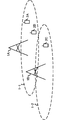
- FIG. 1 is a diagram illustrating an example of a communication system according to the present embodiment.
- the communication system in this embodiment includes base station apparatuses 1A and 1B and terminal apparatuses 2A, 2B and 2C.
- the coverage 1-1 is a range (communication area) in which the base station device 1A can be connected to the terminal device.
- the coverage 1-2 is a range (communication area) in which the base station device 1B can be connected to the terminal device.
- the terminal devices 2A and 2B are also referred to as the terminal device 2.
- the received signal at the terminal device 2 is A desired signal addressed to a device (also referred to as a first terminal device) and a signal addressed to a terminal device (also referred to as a second terminal device) that cause interference are included.
- the received signal in the terminal device 2A includes a desired signal transmitted from the base station device 1A to the own terminal device, a signal addressed to the terminal device 2B, and a signal addressed to the terminal device 2C transmitted from the base station device 1B. And an interference signal.
- the received signal in the terminal device 2B is an interference that is a desired signal addressed to the own terminal device transmitted from the base station device 1A, a signal addressed to the terminal device 2A and a signal addressed to the terminal device 2C transmitted from the base station device 1B. Signal.
- the base station apparatus may be a case where the terminal apparatus receives inter-user interference or another base station apparatus receives inter-cell interference by spatially multiplexing a plurality of terminal apparatuses. It is not limited to the communication system of FIG. Further, it is not necessary to receive inter-user interference and inter-cell interference at the same time, and both the case of receiving only inter-user interference and the case of receiving only inter-cell interference are included in the present invention.
- the following uplink physical channels are used in uplink wireless communication from the terminal apparatus 2 to the base station apparatus 1A.
- the uplink physical channel is used for transmitting information output from an upper layer.
- -PUCCH Physical Uplink Control Channel
- PUSCH Physical Uplink Shared Channel
- PRACH Physical Random Access Channel
- the PUCCH is used for transmitting uplink control information (Uplink Control Information: UCI).
- UCI Uplink Control Information
- the uplink control information includes ACK (a positive acknowledgement) or NACK (a negative acknowledgement) (ACK / NACK) for downlink data (downlink transport block, Downlink-Shared Channel: DL-SCH).
- ACK / NACK for downlink data is also referred to as HARQ-ACK and HARQ feedback.
- the uplink control information includes channel state information (Channel State Information: CSI) for the downlink. Further, the uplink control information includes a scheduling request (Scheduling Request: SR) used to request resources of an uplink shared channel (Uplink-Shared Channel: UL-SCH).
- the channel state information corresponds to a rank index RI that specifies a suitable spatial multiplexing number, a precoding matrix index PMI that specifies a suitable precoder, a channel quality index CQI that specifies a suitable transmission rate, and the like.
- the channel quality indicator CQI (hereinafter referred to as CQI value) may be a suitable modulation scheme (for example, QPSK, 16QAM, 64QAM, 256QAM, etc.) and code rate in a predetermined band (details will be described later). it can.
- the CQI value can be an index (CQI Index) determined by the change method and coding rate.
- the CQI value can be predetermined by the system.
- the rank index and the precoding quality index can be determined in advance by the system.
- the rank index and the precoding matrix index can be indexes determined by the spatial multiplexing number and precoding matrix information.
- the values of the rank index, the precoding matrix index, and the channel quality index CQI are collectively referred to as CSI values.
- the PUSCH is used for transmitting uplink data (uplink transport block, UL-SCH). Moreover, PUSCH may be used to transmit ACK / NACK and / or channel state information together with uplink data. Moreover, PUSCH may be used in order to transmit only uplink control information.
- PUSCH is used to transmit an RRC message.
- the RRC message is information / signal processed in a radio resource control (Radio-Resource-Control: -RRC) layer.
- the PUSCH is used to transmit a MAC CE (Control Element).
- the MAC CE is information / signal processed (transmitted) in the medium access control (MAC) layer.
- the power headroom may be included in the MAC CE and reported via PUSCH. That is, the MAC CE field may be used to indicate the power headroom level.
- PRACH is used to transmit a random access preamble.
- an uplink reference signal (Uplink Reference Signal: UL SRS) is used as an uplink physical signal.
- the uplink physical signal is not used for transmitting information output from the upper layer, but is used by the physical layer.
- the uplink reference signal includes DMRS (Demodulation Reference Signal) and SRS (Sounding Reference Signal).
- DMRS is related to transmission of PUSCH or PUCCH.
- base station apparatus 1A uses DMRS to perform propagation channel correction for PUSCH or PUCCH.
- SRS is not related to PUSCH or PUCCH transmission.
- the base station apparatus 1A uses SRS to measure the uplink channel state.
- the following downlink physical channels are used in downlink wireless communication from the base station apparatus 1A to the terminal apparatus 2.
- the downlink physical channel is used for transmitting information output from an upper layer.
- PBCH Physical Broadcast Channel
- PCFICH Physical Control Format Indicator Channel
- PHICH Physical Hybrid automatic repeat request Indicator Channel: HARQ instruction channel
- PDCCH Physical Downlink Control Channel
- EPDCCH Enhanced Physical Downlink Control Channel
- PDSCH Physical Downlink Shared Channel
- the PBCH is used for broadcasting a master information block (Master Information Block: MIB, Broadcast Channel: BCH) commonly used in the terminal device 2.
- MIB Master Information Block
- BCH Broadcast Channel
- PCFICH is used for transmitting information indicating a region (for example, the number of OFDM symbols) used for transmission of PDCCH.
- PHICH is used to transmit ACK / NACK for uplink data (transport block, codeword) received by the base station apparatus 1A. That is, PHICH is used to transmit a HARQ indicator (HARQ feedback) indicating ACK / NACK for uplink data. ACK / NACK is also referred to as HARQ-ACK.
- the terminal device 2 notifies the received ACK / NACK to the higher layer.
- ACK / NACK is ACK indicating that the data has been correctly received, NACK indicating that the data has not been correctly received, and DTX indicating that there is no corresponding data. Further, when there is no PHICH for the uplink data, the terminal device 2 notifies the upper layer of ACK.
- DCI Downlink Control Information
- a plurality of DCI formats are defined for transmission of downlink control information. That is, fields for downlink control information are defined in the DCI format and mapped to information bits.
- a DCI format 1A used for scheduling one PDSCH (transmission of one downlink transport block) in one cell is defined as a DCI format for the downlink.
- the DCI format for the downlink includes information on PDSCH resource allocation, information on MCS (Modulation and Coding Scheme) for PDSCH, and downlink control information such as a TPC command for PUCCH.
- the DCI format for the downlink is also referred to as a downlink grant (or downlink assignment).
- DCI format 0 used for scheduling one PUSCH (transmission of one uplink transport block) in one cell is defined.
- the DCI format for uplink includes information on PUSCH resource allocation, information on MCS for PUSCH, and uplink control information such as TPC command for PUSCH.
- the DCI format for the uplink is also referred to as uplink grant (or uplink assignment).
- the DCI format for uplink can be used to request downlink channel state information (CSI: “Channel State Information”, also referred to as reception quality information).
- the channel state information includes a rank index RI (Rank Indicator) that designates a suitable spatial multiplexing number, a precoding matrix indicator PMI (Precoding Matrix Indicator) that designates a suitable precoder, and a channel quality indicator CQI (Specify a suitable transmission rate).
- rank index RI Rank Indicator
- PMI Precoding Matrix Indicator
- CQI Specific Transmission Rate
- Channel Quality Indicator Channel Quality Indicator
- the DCI format for the uplink can be used for setting indicating an uplink resource for mapping a channel state information report (CSI feedback report) that the terminal apparatus feeds back to the base station apparatus.
- the channel state information report can be used for setting indicating an uplink resource that periodically reports channel state information (Periodic CSI).
- the channel state information report can be used for mode setting (CSI report mode) for periodically reporting the channel state information.
- the channel state information report can be used for setting indicating an uplink resource for reporting irregular channel state information (Aperiodic CSI).
- the channel state information report can be used for mode setting (CSI report mode) for reporting the channel state information irregularly.
- the base station devices 1A and 1B can set either the periodic channel state information report or the irregular channel state information report.
- the base station apparatuses 1A and 1B can also set both the regular channel state information report and the irregular channel state information report.
- the DCI format for the uplink can be used for setting indicating the type of channel state information report that the terminal apparatus feeds back to the base station apparatus.
- Types of channel state information reports include wideband CSI (for example, Wideband CQI) and narrowband CSI (for example, Subband CQI).
- the DCI format for the uplink it can be used for mode setting including types of the periodic channel state information report or the irregular channel state information report and the channel state information report. For example, a mode for reporting irregular channel state information and wideband CSI, a mode for reporting irregular channel state information and reporting narrowband CSI, an irregular channel state information report, and broadband CSI and narrowband CSI Mode, periodic channel state information report and wideband CSI report mode, periodic channel state information report and narrowband CSI mode, periodic channel state information report and wideband CSI and narrowband CSI There is a mode to report.
- the terminal device 2 When the PDSCH resource is scheduled using the downlink assignment, the terminal device 2 receives the downlink data on the scheduled PDSCH. Moreover, when the PUSCH resource is scheduled using the uplink grant, the terminal device 2 transmits uplink data and / or uplink control information using the scheduled PUSCH.
- the PDSCH is used to transmit downlink data (downlink transport block, DL-SCH).
- the PDSCH is used to transmit a system information block type 1 message.
- the system information block type 1 message is cell specific (cell specific) information.
- PDSCH is used to transmit a system information message.
- the system information message includes a system information block X other than the system information block type 1.
- the system information message is cell specific (cell specific) information.
- PDSCH is used to transmit an RRC message.
- the RRC message transmitted from the base station apparatus 1A may be common to a plurality of terminal apparatuses 2 in the cell.
- the RRC message transmitted from the base station device 1A may be a message dedicated to a certain terminal device 2 (also referred to as dedicated signaling).
- user device specific (user device specific) information is transmitted to a certain terminal device 2 using a dedicated message.
- the PDSCH is used to transmit the MAC CE.
- the RRC message and / or MAC CE is also referred to as higher layer signaling.
- PDSCH can be used to request downlink channel state information.
- the PDSCH can be used to transmit an uplink resource that maps a channel state information report (CSI feedback report) that the terminal device feeds back to the base station device.
- CSI feedback report can be used for setting indicating an uplink resource that periodically reports channel state information (Periodic CSI).
- the channel state information report can be used for mode setting (CSI report mode) for periodically reporting the channel state information.
- the types of downlink channel state information reports include wideband CSI (for example, Wideband CSI) and narrowband CSI (for example, Subband CSI).
- the broadband CSI calculates one channel state information for the system band of the cell.
- the narrowband CSI the system band is divided into predetermined units, and one channel state information is calculated for the division.
- a synchronization signal (Synchronization signal: SS) and a downlink reference signal (Downlink Signal: DL RS) are used as downlink physical signals.
- the downlink physical signal is not used to transmit information output from the upper layer, but is used by the physical layer.
- the synchronization signal is used by the terminal device 2 to synchronize the downlink frequency domain and time domain. Further, the downlink reference signal is used by the terminal device 2 for performing channel correction of the downlink physical channel. For example, the downlink reference signal is used by the terminal device 2 to calculate downlink channel state information.
- the downlink reference signal includes CRS (Cell-specific Reference Signal: UE-specific reference signal), URS (UE-specific Reference Signal: UE-specific reference signal) related to PDSCH, DMRS (Demodulation Reference) related to EPDCCH. Signal), NZP CSI-RS (Non-Zero Power Chanel State Information Reference Signal), ZP CSI-RS (Zero Power Chanel State Information Reference Signal).
- CRS Cell-specific Reference Signal: UE-specific reference signal
- URS UE-specific Reference Signal: UE-specific reference signal
- DMRS Demodulation Reference
- NZP CSI-RS Non-Zero Power Chanel State Information Reference Signal
- ZP CSI-RS Zero Power Chanel State Information Reference Signal
- CRS is transmitted in the entire band of the subframe, and is used to demodulate PBCH / PDCCH / PHICH / PCFICH / PDSCH.
- the URS associated with the PDSCH is transmitted in subframes and bands used for transmission of the PDSCH associated with the URS, and is used to demodulate the PDSCH associated with the URS.
- DMRS related to EPDCCH is transmitted in subframes and bands used for transmission of EPDCCH related to DMRS.
- DMRS is used to demodulate the EPDCCH with which DMRS is associated.
- NZP CSI-RS resources are set by the base station apparatus 1A.
- the terminal device 2 performs signal measurement (channel measurement) using NZP CSI-RS.
- the resource of ZP CSI-RS is set by the base station apparatus 1A.
- the base station apparatus 1A transmits ZP CSI-RS with zero output.
- the terminal device 2 measures interference in a resource supported by NZP CSI-RS.
- ZP CSI-RS resources are set by the base station device 1A.
- the base station apparatus 1B transmits ZP CSI-RS with zero output. That is, the base station device 1A does not transmit the ZP CSI-RS.
- the base station apparatus 1B does not transmit PDSCH and EPDCCH using resources set by ZP CSI-RS.
- the terminal device 2C can measure interference in a resource corresponding to NZP CSI-RS in a certain cell.
- MBSFN Multimedia Broadcast Multicast Service Single Frequency Network
- the MBSFN RS is used for PMCH demodulation.
- PMCH is transmitted through an antenna port used for transmission of MBSFN RS.
- the downlink physical channel and the downlink physical signal are collectively referred to as a downlink signal.
- the uplink physical channel and the uplink physical signal are collectively referred to as an uplink signal.
- the downlink physical channel and the uplink physical channel are collectively referred to as a physical channel.
- the downlink physical signal and the uplink physical signal are collectively referred to as a physical signal.
- BCH, UL-SCH and DL-SCH are transport channels.
- a channel used in the MAC layer is referred to as a transport channel.
- the unit of the transport channel used in the MAC layer is also referred to as a transport block (Transport Block: TB) or a MAC PDU (Protocol Data Unit).
- the transport block is a unit of data that is delivered (delivered) by the MAC layer to the physical layer. In the physical layer, the transport block is mapped to a code word, and an encoding process or the like is performed for each code word.
- the terminal device can have a function of removing or suppressing inter-user interference and inter-cell interference.
- a technique is considered as NAICS (Network Assisted Interference Cancellation and Suppression) by 3GPP (3rd Generation Partnership Project).
- NAICS Network Assisted Interference Cancellation and Suppression
- a base station apparatus transmits NAICS assist information (also referred to as support information or first support information) used by a terminal apparatus for handling, removing, or suppressing an interference signal.
- the terminal device receives the NAICS assist information, detects a parameter for removing or suppressing the interference signal based on the NAICS assist information, and removes or suppresses the interference signal using the parameter.
- the NAICS assist information includes cell ID, number of CRS antenna ports, MBSFN subframe setting list, PB, virtual cell ID (virtual cell ID), scrambling identity (nSCID), PA, transmission mode, QCL information (quasi co-location information), ZP / NZP CSI-RS configuration, PDSCH start position (PDSCH starting position), TDD UL / DL configuration, precoding matrix index / rank index, modulation scheme, and part or all of resource allocation information.
- PA is a power ratio of PDSCH and CRS in an OFDM symbol in which CRS is not arranged.
- PB represents the power ratio of PDSCH in the OFDM symbol in which CRS is not arranged and PDSCH in the OFDM symbol in which CRS is not arranged.
- the QCL information is information related to the QCL for a predetermined antenna port, a predetermined signal, or a predetermined channel. In two antenna ports, if the long-term characteristics of the channel carrying the symbol on one antenna port can be inferred from the channel carrying the symbol on the other antenna port, those antenna ports are QCL It is called. Long interval characteristics include delay spread, Doppler spread, Doppler shift, average gain and / or average delay. That is, when the two antenna ports are QCL, the terminal device can be regarded as having the same long section characteristics at the antenna ports.
- the NAICS function includes MU-MIMO (Multi-user Multiple Input Multiple Output) that spatially multiplexes signals addressed to a plurality of terminal devices on the base station device side or non-orthogonal access
- the base station device Information regarding non-orthogonal access can also be included in the NAICS assist information.
- Inter-user interference in MU-MIMO or non-orthogonal access is also called intra-cell interference.
- a different transmission power is assigned to a signal addressed to each terminal device, and when the transmission power or reception power of a signal addressed to another terminal device (that is, an interference signal) is larger than the signal addressed to the terminal device itself
- the device removes or suppresses interference signals due to NAICS.
- the transmission power or reception power of the interference signal is smaller than that of the signal addressed to the own terminal device, the interference signal is not necessarily removed or suppressed by NAICS (may be performed).
- Information on MU-MIMO and non-orthogonal access is, for example, information on whether the base station apparatus supports MU-MIMO and non-orthogonal access (for example, transmission mode) and transmission power.
- one value (candidate) may be set for each of the parameters included in the NAICS assist information, or a plurality of values (candidates) may be set.
- the terminal device interprets that the parameter indicates a value that may be set by the base station device that causes interference, and sets the interference signal from the multiple values. Detect the parameters that are being used.
- the NAICS assist information may indicate information of another base station apparatus or may indicate information of its own base station apparatus.
- the NAICS assist information is used by the terminal device to handle, remove, or suppress interference from the PDSCH to other terminal devices when demodulating the PDSCH for the terminal device. Therefore, the NAICS assist information is also referred to as PDSCH interference assist information or PDSCH assist information.
- the NAICS assist information includes at least information related to mapping of PDSCH resource elements to other terminal apparatuses.
- the NAICS assist information may be used when performing various measurements.
- the measurement includes RRM (Radio Resource Management) measurement, RLM (Radio Link Monitoring) measurement, and CSI (Channel State Information) measurement.
- the terminal device detects (identifies) PDSCH interference based on the set NAICS assist information, and reduces the detected PDSCH interference.
- the NAICS assist information may include quasi-static control information with a relatively long update frequency, and may not include dynamic control information with a relatively low update frequency.
- the quasi-static control information includes cell ID, number of CRS antenna ports, MBSFN subframe pattern, PB, virtual cell ID (virtual cell ID), scrambling identity (nSCID), PA, transmission mode, QCL information (quasi co- location information), ZP / NZP CSI-RS configuration, PDSCH starting position, TDD UL / DL configuration, etc.
- the dynamic control information includes a precoding matrix index / rank index, a modulation scheme, resource allocation information, and the like.
- the NAICS assist information can be regarded as information for indicating a plurality of PDSCH interference candidates.
- the terminal device can perform blind detection in an attempt to detect PDSCH interference candidates that can be recognized based on NAICS assist information in order.
- the terminal device can reduce interference by PDSCH with respect to other terminal devices based on the parameters detected from the NAICS assist information, a signal addressed to the terminal device can be obtained with high accuracy.
- the NAICS assist information indicates a plurality of candidates, the influence on the scheduling of the base station apparatus can be reduced.
- the terminal device may perform blind detection on a parameter that has not been received as assist information.
- linear detection or non-linear detection can be performed.
- the linear detection can be performed in consideration of the channel of the desired signal addressed to the own terminal device and the channel of the interference signal addressed to the other terminal device.
- Such linear detection is also called ELMMSE-IRC (Enhanced-Linear-Minimum-Mean-Square-Error-Interference-Rejection-Combining).
- interference canceller or maximum likelihood detection can be performed.
- the base station apparatus can transmit the NAICS assist information in a list as a NAICS assist information list.
- the NAICS assist information list can include at least one NAICS assist information.
- the NAICS assist information list can be transmitted as neighboring cell NAICS information (also referred to as first interference information).
- the NAICS assist information list may be referred to as a PDSCH assist information list.
- the neighbor cell NAICS information may be referred to as neighbor cell PDSCH information.
- the terminal apparatus uses the CRS assist information (also referred to as second support information) transmitted from the base station apparatus using an upper layer signal, Interference received from the CRS of the base station apparatus can be reduced.
- the CRS assist information is information on other base station apparatuses, and includes a cell ID, the number of CRS antenna ports, and an MBSFN subframe setting list.
- the CRS assist information is sent as a list by the CRS assist information list.
- the CRS assist information list includes at least one CRS assist information.
- the CRS assist information list is transmitted as neighboring cell CRS information (also referred to as second interference information).
- the CRS assist information is used by the terminal device for handling, removing, or suppressing interference from the CRS of another cell (neighboring cell) when demodulating the PDSCH for the terminal device.
- the CRS assist information may be used when performing various measurements.
- the measurement includes RRM (Radio Resource Management) measurement, RLM (Radio Link Monitoring) measurement, and CSI (Channel State Information) measurement.
- the NAICS assist information can be used not only when the terminal apparatus handles not only PDSCH interference but also CRS interference and other channel interference.
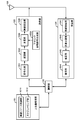
- FIG. 2 is a schematic block diagram showing the configuration of the base station apparatus 1A in the present embodiment.
- the base station apparatus 1A includes an upper layer processing unit 101, a control unit 102, a transmission unit 103, a reception unit 104, and a transmission / reception antenna 105.
- the upper layer processing unit 101 includes a radio resource control unit 1011 and a scheduling unit 1012.
- the transmission unit 103 includes an encoding unit 1031, a modulation unit 1032, a downlink reference signal generation unit 1033, a multiplexing unit 1034, and a wireless transmission unit 1035.
- the reception unit 104 includes a wireless reception unit 1041, a demultiplexing unit 1042, a demodulation unit 1043, and a decoding unit 1044.
- the upper layer processing unit 101 includes a medium access control (Medium Access Control: MAC) layer, a packet data integration protocol (Packet Data Convergence Protocol: PDCP) layer, a radio link control (Radio Link Control: RLC) layer, a radio resource control (Radio) Resource (Control: RRC) layer processing.
- MAC Medium Access Control
- PDCP Packet Data Convergence Protocol
- RLC Radio Link Control
- RRC radio resource control
- upper layer processing section 101 generates information necessary for controlling transmission section 103 and reception section 104 and outputs the information to control section 102.
- the upper layer processing unit 101 receives information related to the terminal device such as the function (UE capability) of the terminal device from the terminal device. In other words, the terminal apparatus transmits its own function to the base station apparatus using an upper layer signal.
- the function of the terminal device can include a parameter indicating whether NAICS is supported.
- the terminal apparatus can transmit to the base station apparatus by using individual parameters whether each function is supported. For example, when two functions of PDSCH interference handling and CRS interference handling are included as NAICS, the terminal apparatus indicates a signal indicating whether PDSCH interference handling is supported, and indicates whether CRS interference handling is supported. The signal can be transmitted to the base station apparatus.
- NAICS includes a function for removing or suppressing inter-user interference such as MU-MIMO or non-orthogonal access
- a signal indicating whether inter-user interference handling is supported is transmitted to the base station apparatus. can do.
- Inter-user interference handling may be a function included in PDSCH interference handling. That is, it can be assumed that a terminal device that supports PDSCH interference handling has a function of handling inter-cell interference and inter-user interference.
- information on a terminal device includes information indicating whether the terminal device supports a predetermined function, or information indicating that the terminal device has introduced a predetermined function and has completed a test.
- whether or not to support a predetermined function includes whether or not installation and testing for the predetermined function have been completed.
- the terminal device transmits information (parameters) indicating whether the predetermined function is supported.
- the terminal device does not transmit information (parameter) indicating whether or not the predetermined device is supported. That is, whether or not to support the predetermined function is notified by whether or not information (parameter) indicating whether or not to support the predetermined function is transmitted. Note that information (parameter) indicating whether or not to support a predetermined function may be notified using 1 bit of 1 or 0.
- the upper layer processing unit 101 determines whether or not to set NAICS assist information and whether or not to set CRS assist information.
- the base station apparatus can determine whether or not to set NAICS assist information from the function of the terminal apparatus.
- the radio resource control unit 1011 generates or acquires downlink data (transport block), system information, RRC message, MAC CE, and the like arranged on the downlink PDSCH from the upper node.
- the radio resource control unit 1011 outputs downlink data to the transmission unit 103 and outputs other information to the control unit 102.
- the radio resource control unit 1011 manages various setting information of the terminal device 2.
- This setting information can include setting information of a terminal device that causes interference.
- the setting information of the terminal device that causes interference can be acquired from the setting information of the own terminal device.
- the setting information of the base station apparatus that causes interference can be included.
- the scheduling unit 1012 determines the frequency and subframe to which the physical channels (PDSCH and PUSCH) are allocated, the coding rate and modulation scheme (or MCS) of the physical channels (PDSCH and PUSCH), transmission power, and the like.
- the scheduling unit 1012 outputs the determined information to the control unit 102.
- the scheduling unit 1012 generates information used for physical channel (PDSCH and PUSCH) scheduling based on the scheduling result.
- the scheduling unit 1012 outputs the generated information to the control unit 102.
- the scheduling unit 1012 schedules the terminal device 2A and the terminal device 2B to the same resource. In this embodiment, for the sake of simplicity, the same resource is used. However, different resources may be scheduled. Note that scheduling can be performed in cooperation with the base station apparatus 1B.
- the control unit 102 generates a control signal for controlling the transmission unit 103 and the reception unit 104 based on the information input from the higher layer processing unit 101.
- the control unit 102 generates downlink control information based on the information input from the higher layer processing unit 101 and outputs the downlink control information to the transmission unit 103.
- the transmission unit 103 generates a downlink reference signal according to the control signal input from the control unit 102, and encodes the HARQ indicator, downlink control information, and downlink data input from the higher layer processing unit 101. Then, PHICH, PDCCH, EPDCCH, PDSCH, and downlink reference signal are multiplexed, and the signal is transmitted to the terminal apparatus 2 via the transmission / reception antenna 105.
- the encoding unit 1031 uses a predetermined encoding method such as block encoding, convolutional encoding, and turbo encoding for the HARQ indicator, downlink control information, and downlink data input from the higher layer processing unit 101. Encoding is performed using the encoding method determined by the radio resource control unit 1011.
- the modulation unit 1032 converts the encoded bits input from the encoding unit 1031 into BPSK (Binary Phase Shift Shift Keying), QPSK (quadrature Phase Shift Shift Keying), 16 QAM (quadrature Amplitude Modulation), 64 QAM, 256 QAM, and the like. Or it modulates with the modulation system which the radio
- the downlink reference signal generation unit 1033 is a sequence that is known by the terminal device 2 and is obtained by a predetermined rule based on a physical cell identifier (Physical cell identity: PCI, cell ID) for identifying the base station device 1A. As a downlink reference signal.
- a physical cell identifier Physical cell identity: PCI, cell ID
- the multiplexing unit 1034 multiplexes the modulated modulation symbol of each channel, the generated downlink reference signal, and downlink control information. That is, multiplexing section 1034 arranges the modulated modulation symbol of each channel, the generated downlink reference signal, and downlink control information in the resource element.
- the radio transmission unit 1035 generates an OFDM symbol by performing inverse fast Fourier transform (Inverse Fourier Transform: IFFT) on the multiplexed modulation symbol and the like, and adds a cyclic prefix (cyclic prefix: CP) to the OFDM symbol.
- IFFT inverse fast Fourier transform
- CP cyclic prefix
- the receiving unit 104 separates, demodulates, and decodes the received signal received from the terminal device 2 via the transmission / reception antenna 105 according to the control signal input from the control unit 102, and outputs the decoded information to the upper layer processing unit 101. .
- the radio reception unit 1041 converts an uplink signal received via the transmission / reception antenna 105 into a baseband signal by down-conversion, removes unnecessary frequency components, and amplifies the signal level so that the signal level is properly maintained.
- the level is controlled, quadrature demodulation is performed based on the in-phase component and the quadrature component of the received signal, and the analog signal that has been demodulated is converted into a digital signal.
- the wireless reception unit 1041 removes a portion corresponding to the CP from the converted digital signal.
- Radio receiving section 1041 performs fast Fourier transform (FFT) on the signal from which CP has been removed, extracts a signal in the frequency domain, and outputs the signal to demultiplexing section 1042.
- FFT fast Fourier transform
- the demultiplexing unit 1042 demultiplexes the signal input from the wireless reception unit 1041 into signals such as PUCCH, PUSCH, and uplink reference signal. This separation is performed based on radio resource allocation information included in the uplink grant that is determined in advance by the radio resource control unit 1011 by the base station apparatus 1A and notified to each terminal apparatus 2.
- the demultiplexing unit 1042 compensates for the propagation paths of the PUCCH and PUSCH. Further, the demultiplexing unit 1042 demultiplexes the uplink reference signal.
- the demodulator 1043 performs inverse discrete Fourier transform (Inverse Discrete Fourier Transform: IDFT) on the PUSCH, acquires modulation symbols, and pre-modulates BPSK, QPSK, 16QAM, 64QAM, 256QAM, etc. for each of the PUCCH and PUSCH modulation symbols.
- IDFT inverse discrete Fourier transform
- the received signal is demodulated by using a modulation method determined or notified in advance by the own device to each of the terminal devices 2 using an uplink grant.
- the decoding unit 1044 uses the coding rate of the demodulated PUCCH and PUSCH in a predetermined encoding method, the predetermined coding method, or the coding rate notified by the own device to the terminal device 2 using the uplink grant. Decoding is performed, and the decoded uplink data and uplink control information are output to the upper layer processing section 101. When PUSCH is retransmitted, decoding section 1044 performs decoding using the coded bits held in the HARQ buffer input from higher layer processing section 101 and the demodulated coded bits.
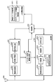
- FIG. 3 is a schematic block diagram showing the configuration of the terminal device 2 in the present embodiment.
- the terminal device 2 includes an upper layer processing unit 201, a control unit 202, a transmission unit 203, a reception unit 204, a channel state information generation unit 205, and a transmission / reception antenna 206.
- the upper layer processing unit 201 includes a radio resource control unit 2011 and a scheduling information interpretation unit 2012.
- the transmission unit 203 includes an encoding unit 2031, a modulation unit 2032, an uplink reference signal generation unit 2033, a multiplexing unit 2034, and a wireless transmission unit 2035.
- the reception unit 204 includes a wireless reception unit 2041, a demultiplexing unit 2042, and a signal detection unit 2043.
- the upper layer processing unit 201 outputs uplink data (transport block) generated by a user operation or the like to the transmission unit 203. Further, the upper layer processing unit 201 includes a medium access control (Medium Access Control: MAC) layer, a packet data integration protocol (Packet Data Convergence Protocol: PDCP) layer, a radio link control (Radio Link Control: RLC) layer, and a radio resource control. Process the (Radio Resource Control: RRC) layer.
- Medium Access Control Medium Access Control: MAC
- PDCP Packet Data Convergence Protocol
- RLC Radio Link Control
- RRC Radio Resource Control
- the upper layer processing unit 201 outputs information indicating the function of the terminal device supported by the own terminal device to the transmission unit 203.
- the radio resource control unit 2011 manages various setting information of the own terminal device. Also, the radio resource control unit 2011 generates information arranged in each uplink channel and outputs the information to the transmission unit 203.
- the radio resource control unit 2011 acquires setting information regarding CSI feedback transmitted from the base station apparatus, and outputs the setting information to the control unit 202.
- the scheduling information interpretation unit 2012 interprets the downlink control information received via the reception unit 204 and determines scheduling information.
- the scheduling information interpretation unit 2012 generates control information for controlling the reception unit 204 and the transmission unit 203 based on the scheduling information, and outputs the control information to the control unit 202.
- the control unit 202 generates a control signal for controlling the receiving unit 204, the channel state information generating unit 205, and the transmitting unit 203 based on the information input from the higher layer processing unit 201.
- the control unit 202 controls the reception unit 204 and the transmission unit 203 by outputting the generated control signal to the reception unit 204, the channel state information generation unit 205, and the transmission unit 203.
- the control unit 202 controls the transmission unit 203 to transmit the CSI generated by the channel state information generation unit 205 to the base station apparatus.
- the receiving unit 204 separates, demodulates, and decodes the received signal received from the base station apparatus 1A via the transmission / reception antenna 206 according to the control signal input from the control unit 202, and sends the decoded information to the upper layer processing unit 201. Output.
- the receiving unit 204 includes a reference signal (also referred to as a first reference signal) corresponding to the base station apparatus 1A included in the received signal, and a reference signal (second reference) based on interference information set by the base station apparatus 1A. (Also referred to as a signal) and output to the channel state information generation unit 205.
- the radio reception unit 2041 converts a downlink signal received via the transmission / reception antenna 206 into a baseband signal by down-conversion, removes unnecessary frequency components, and increases the amplification level so that the signal level is appropriately maintained. , And quadrature demodulation based on the in-phase and quadrature components of the received signal, and converting the quadrature demodulated analog signal into a digital signal.
- the wireless reception unit 2041 removes a portion corresponding to CP from the converted digital signal, performs fast Fourier transform on the signal from which CP is removed, and extracts a frequency domain signal.
- the demultiplexing unit 2042 separates the extracted signal into PHICH, PDCCH, EPDCCH, PDSCH, and downlink reference signal. Further, the demultiplexing unit 2042 compensates for the PHICH, PDCCH, and EPDCCH channels based on the channel estimation value of the desired signal obtained from the channel measurement, detects downlink control information, and sends it to the control unit 202. Output. In addition, control unit 202 outputs PDSCH and the channel estimation value of the desired signal to signal detection unit 2043.
- the signal detection unit 2043 detects a signal using the PDSCH and the channel estimation value, and outputs the signal to the higher layer processing unit 201.
- signal detection is performed by removing or suppressing the interference signal.
- the removal or suppression of the interference signal for example, linear detection considering the channel estimation value of the interference signal, or interference cancellation or maximum likelihood detection considering the channel estimation value of the interference signal and the modulation method are performed.
- the signal detection unit 2043 detects (identifies) parameters necessary for interference channel estimation and / or demodulation of the interference signal. For parameters for which a plurality of values are set in the NAICS assist information, a plurality of values are used as candidates, and the values set in the interference signal are blind-detected. In addition, for parameters that are not set in the NAICS assist information, values that may be set in the system may be candidates, and values set in the interference signal may be detected blindly. The signal detection unit 2043 removes or suppresses the PDSCH / CRS interference signal using the detected parameter.
- detecting the parameter of the interference signal increases the amount of computation of the terminal device, so it is desirable to detect only necessary information.
- Information necessary for demodulation can be determined by the parameters of the signal addressed to the terminal device itself and some parameters set in the interference signal.
- the terminal device when the number of layers included in the downlink control information transmitted from the serving cell is 3 or more, the terminal device does not remove or suppress the interference signal based on the NAICS assist information even if the NAICS assist information is set. be able to. At this time, since the parameter of the interference signal is not blind-detected based on the NAICS assist information, the calculation amount of the terminal device can be reduced.
- the terminal apparatus does not assume MU-MIMO. That is, the interference signal is removed or suppressed based on NAICS assist information regarding a physical cell ID different from the physical cell ID of the serving cell.
- NAICS assist information related to the same physical cell ID as that of the serving cell can be excluded from the candidates, so that the amount of computation of the terminal device can be reduced.
- the terminal apparatus does not assume MU-MIMO, and the terminal apparatus does not remove or suppress the interference signal based on NAICS assist information. Therefore, the calculation amount of the terminal device can be reduced.
- the terminal device does not assume TM1, TM2, TM3, TM4, and TM6 among the transmission modes included in the NAICS assist information. That is, the transmission mode included in the NAICS assist information is limited to the DMRS-based transmission mode.
- the DMRS-based transmission mode is, for example, TM8 / 9/10. In this case, the terminal device can limit the antenna port number to 7 or 8 interference signals.
- the terminal apparatus removes or suppresses the interference signal assuming MU-MIMO.
- the terminal device can perform blind detection assuming that the antenna port number of the interference signal is 7 or 8.
- the terminal device can determine that MU-MIMO is being performed, it can remove or suppress the interference signal assuming MU-MIMO.
- the terminal apparatus determines that the MU-MIMO is performed, it is not necessary to perform blind detection on at least a cell-specific parameter, and the amount of calculation of the terminal apparatus can be reduced.
- Cell-specific parameters are, for example, QCL information, ZP / NZP CSI-RS configuration, PDSCH start position, TDD UL / DL configuration, and the like.
- the terminal device As a method for determining whether or not the terminal device is MU-MIMO, for example, it is possible to know that the terminal device is MU-MIMO by blind detection of some of the parameters of the interference signal.
- the parameters necessary for the terminal device to determine whether MU-MIMO is used are less than those required to eliminate or suppress inter-cell interference. Therefore, if it can be determined that MU-MIMO is used, the amount of computation is reduced. Can be reduced.
- the terminal device can determine from an initial value of a pseudo-random sequence corresponding to a terminal-specific reference signal associated with the PDSCH.
- the initial value c init of the pseudorandom sequence corresponding to the terminal-specific reference signal associated with the PDSCH is expressed by the following equation (1).
- n s denotes a slot number within a radio frame.
- n ID (i) is also referred to as a first variable.
- the terminal device has a terminal-specific reference associated with the PDSCH assumed based on the value of the first variable constituting the initial value of the pseudo-random sequence corresponding to the terminal-specific reference signal associated with the PDSCH of the serving cell and the NAICS assist information.
- the interference signal can be removed or suppressed assuming MU-MIMO.
- the terminal apparatus also includes an initial value of a pseudo-random sequence corresponding to a terminal-specific reference signal associated with the PDSCH of the serving cell and a pseudo-random sequence corresponding to a terminal-specific reference signal associated with the PDSCH assumed based on the NAICS assist information. If the initial values are the same, interference signals can be removed or suppressed assuming MU-MIMO.
- the terminal device corresponds to a terminal-specific reference signal associated with the PDSCH assumed based on the NAICS assist information when the transmission mode of the terminal device is TM10 and the virtual cell ID is not set in the upper layer.
- the terminal device can remove or suppress the interference signal assuming MU-MIMO.
- Another method for determining whether the terminal apparatus is MU-MIMO is that the base station apparatus transmits information indicating that the terminal apparatus is MU-MIMO or intra-cell interference to the terminal apparatus.
- the terminal device is MU-MIMO.
- the base station apparatus can signal whether the terminal apparatus is MU-MIMO using a higher layer signal or a physical layer signal (for example, downlink control information).
- the base station apparatus When the base station apparatus performs signaling to the terminal apparatus using an upper layer signal, the base station apparatus individually sets NAICS assist information corresponding to inter-cell interference and / or NAICS assist information corresponding to MU-MIMO. In this case, the terminal apparatus removes or suppresses the interference signal based on NAICS assist information corresponding to inter-cell interference and / or MU-MIMO.
- the base station device When the base station device signals to the terminal device whether it is MU-MIMO with a physical layer signal and the transmission mode of the terminal device is TM8 / 9, or the virtual cell ID is set in TM10 If not, the interference signal parameter is blind detected assuming MU-MIMO.
- the interference signal parameter is blind detected assuming MU-MIMO.
- blind detection is possible even when there is no assist information, because the antenna port is different between users, the scrambling identity is different, and the antenna port and scrambling identity are different. is there. Therefore, for example, if there is 1-bit signaling indicating whether or not MU-MIMO is performed in the physical layer signal from the base station apparatus, the terminal apparatus can perform inter-user interference even if NAICS assist information is not set. Can be removed or suppressed.
- the base station device signals to the terminal device whether or not MU-MIMO is performed using a physical layer signal
- the terminal device Assumes that the virtual cell ID is also set in TM10 for the interference signal, and other parameters can be blindly detected.
- the first variable constituting the initial value of the pseudo-random sequence of the terminal-specific reference signal associated with the PDSCH addressed to the terminal device and the pseudo-random sequence of the terminal-specific reference signal associated with the PDSCH of the interference signal It can be assumed that the first variable constituting the initial value is the same.
- the terminal device can determine whether or not non-orthogonal access is performed, it can remove or suppress the interference signal assuming non-orthogonal access. For example, when different transmission power is allocated between multiplexed terminal apparatuses, when the transmission power of the interference signal is larger than the transmission power of the signal addressed to the own terminal apparatus, the interference signal is removed by NAICS. Alternatively, since suppression is necessary, the terminal device must detect a parameter set in the interference signal. On the other hand, if the transmission power of the interference signal is smaller than the transmission power of the signal destined for the terminal device, it is not always necessary to remove or suppress the interference signal by NAICS, so the parameter set in the interference signal is detected. It is not necessary. In this case, the calculation amount of the terminal device can be reduced.
- the base station device can communicate in a transmission mode corresponding to non-orthogonal access or in a DCI format corresponding to non-orthogonal access.
- the DCI format corresponding to non-orthogonal access includes at least information regarding power control.
- the information related to power control is, for example, the power difference between the transmission power addressed to the terminal device and the transmission power of the interference signal, and the power control information of the interference signal.
- a predetermined power offset value is set in the power control information of the interference signal, and the positive / negative can be signaled by 1 bit.
- the power control information of the interference signal can be determined by blind detection. This blind detection may be performed based on assist information regarding power control.
- the terminal apparatus satisfies the conditions for determining MU-MIMO, compares the PA set for the signal addressed to itself with the PA set for the interference signal, and If the PA set for the signal is larger than the PA set for the interference signal, the interference signal is not removed or suppressed by NAICS. On the other hand, when the PA set in the signal addressed to the terminal device is smaller than the PA set in the interference signal, the interference signal is removed or suppressed by NAICS.
- the transmission unit 203 generates an uplink reference signal according to the control signal input from the control unit 202, encodes and modulates the uplink data (transport block) input from the higher layer processing unit 201, PUCCH, The PUSCH and the generated uplink reference signal are multiplexed and transmitted to the base station apparatus 1A via the transmission / reception antenna 206.
- the encoding unit 2031 performs encoding such as convolutional encoding and block encoding on the uplink control information input from the higher layer processing unit 201. Also, the coding unit 2031 performs turbo coding based on information used for PUSCH scheduling.
- the modulation unit 2032 modulates the coded bits input from the coding unit 2031 using a modulation scheme notified by downlink control information such as BPSK, QPSK, 16QAM, 64QAM, or a modulation scheme predetermined for each channel. .
- the uplink reference signal generation unit 2033 includes parameters for generating a physical cell identifier for identifying the base station apparatus 1A, a bandwidth for arranging the uplink reference signal, a cyclic shift notified by the uplink grant, and a DMRS sequence. Based on the value or the like, a sequence determined by a predetermined rule (formula) is generated.
- the multiplexing unit 2034 rearranges the PUSCH modulation symbols in parallel according to the control signal input from the control unit 202, and then performs a discrete Fourier transform (DFT). Also, the multiplexing unit 2034 multiplexes the PUCCH and PUSCH signals and the generated uplink reference signal for each transmission antenna port. That is, multiplexing section 2034 arranges the PUCCH and PUSCH signals and the generated uplink reference signal in the resource element for each transmission antenna port.
- DFT discrete Fourier transform
- the radio transmission unit 2035 performs inverse fast Fourier transform (Inverse Fast Fourier Transform: IFFT) on the multiplexed signal, performs SC-FDMA modulation, generates an SC-FDMA symbol, and generates the generated SC-FDMA symbol.
- IFFT inverse Fast Fourier Transform
- CP is added to baseband digital signal, baseband digital signal is converted to analog signal, excess frequency component is removed, converted to carrier frequency by up-conversion, power amplification, transmission / reception antenna It outputs to 206 and transmits.
- the program that operates in the base station apparatus and the terminal apparatus according to the present invention is a program (a program that causes a computer to function) that controls the CPU and the like so as to realize the functions of the above-described embodiments according to the present invention.
- Information handled by these devices is temporarily stored in the RAM at the time of processing, then stored in various ROMs and HDDs, read out by the CPU, and corrected and written as necessary.
- a recording medium for storing the program a semiconductor medium (for example, ROM, nonvolatile memory card, etc.), an optical recording medium (for example, DVD, MO, MD, CD, BD, etc.), a magnetic recording medium (for example, magnetic tape, Any of a flexible disk etc. may be sufficient.
- the processing is performed in cooperation with the operating system or other application programs.
- the functions of the invention may be realized.
- the program when distributing to the market, can be stored and distributed on a portable recording medium, or transferred to a server computer connected via a network such as the Internet.
- the storage device of the server computer is also included in the present invention.
- LSI which is typically an integrated circuit.
- Each functional block of the receiving apparatus may be individually chipped, or a part or all of them may be integrated into a chip. When each functional block is integrated, an integrated circuit controller for controlling them is added.
- the method of circuit integration is not limited to LSI, and may be realized by a dedicated circuit or a general-purpose processor.
- an integrated circuit based on the technology can also be used.
- the terminal device of the present invention is not limited to application to a mobile station device, but is a stationary or non-movable electronic device installed indoors or outdoors, such as AV equipment, kitchen equipment, cleaning / washing equipment Needless to say, it can be applied to air conditioning equipment, office equipment, vending machines, and other daily life equipment.
- the present invention is suitable for use in a terminal device, a base station device, and a communication method.
Landscapes
- Engineering & Computer Science (AREA)
- Signal Processing (AREA)
- Computer Networks & Wireless Communication (AREA)
- Quality & Reliability (AREA)
- Mobile Radio Communication Systems (AREA)
- Monitoring And Testing Of Transmission In General (AREA)
- Noise Elimination (AREA)
Abstract
Le problème décrit par la présente invention est de diminuer les interférences tout en limitant l'augmentation de la quantité de calculs par l'utilisation des connaissances ou des informations effectives concernant un signal d'interférence. Un dispositif terminal est muni d'une unité de réception qui reçoit des informations de commande de liaison descendante en provenance d'un dispositif de station de base. Ledit dispositif terminal, dans le cas d'un mode de transmission prédéfini, démodule un canal commun de liaison descendante envoyé au dispositif en fonction d'un écart de puissance électrique entre la puissance électrique de transmission du dispositif et la puissance électrique de transmission d'un autre dispositif dans un canal commun de liaison descendante compris dans les informations de commande de liaison descendante. L'opportunité de l'exécution d'une suppression d'interférences en fonction de la valeur de l'écart de puissance électrique est également établie.
Priority Applications (1)
| Application Number | Priority Date | Filing Date | Title |
|---|---|---|---|
| US15/504,546 US10447320B2 (en) | 2014-08-20 | 2015-07-31 | Terminal apparatus, base station apparatus, and communication method |
Applications Claiming Priority (2)
| Application Number | Priority Date | Filing Date | Title |
|---|---|---|---|
| JP2014-167061 | 2014-08-20 | ||
| JP2014167061A JP2017183761A (ja) | 2014-08-20 | 2014-08-20 | 端末装置、基地局装置および通信方法 |
Publications (1)
| Publication Number | Publication Date |
|---|---|
| WO2016027646A1 true WO2016027646A1 (fr) | 2016-02-25 |
Family
ID=55350592
Family Applications (1)
| Application Number | Title | Priority Date | Filing Date |
|---|---|---|---|
| PCT/JP2015/071879 Ceased WO2016027646A1 (fr) | 2014-08-20 | 2015-07-31 | Dispositif terminal, dispositif de station de base et procédé de communication |
Country Status (3)
| Country | Link |
|---|---|
| US (1) | US10447320B2 (fr) |
| JP (1) | JP2017183761A (fr) |
| WO (1) | WO2016027646A1 (fr) |
Cited By (1)
| Publication number | Priority date | Publication date | Assignee | Title |
|---|---|---|---|---|
| CN116242336A (zh) * | 2023-03-14 | 2023-06-09 | 东南大学 | 一种物理地图与射频地图同时构建及互惠增强的方法 |
Families Citing this family (6)
| Publication number | Priority date | Publication date | Assignee | Title |
|---|---|---|---|---|
| US10333683B2 (en) * | 2015-05-15 | 2019-06-25 | Telefonaktiebolaget Lm Ericsson (Publ) | Thresholds for radio link monitoring with advanced receivers |
| US11515925B2 (en) * | 2018-05-09 | 2022-11-29 | Nokia Technologies Oy | Selecting and using a subset of beam failure detection resources |
| CN112491456A (zh) * | 2019-09-11 | 2021-03-12 | 索尼公司 | 电子设备、无线通信方法和计算机可读存储介质 |
| WO2021243483A1 (fr) * | 2020-05-30 | 2021-12-09 | Qualcomm Incorporated | Indication de quasi co-localisation (qcl) de liaison latérale à trp multiples pour permettre une prédiction de commande de gain automatique (agc) |
| US12213163B2 (en) * | 2022-02-02 | 2025-01-28 | Qualcomm Incorporated | Enhancement to interference cancellation |
| WO2023184549A1 (fr) * | 2022-04-02 | 2023-10-05 | 北京小米移动软件有限公司 | Procédé et appareil antibrouillage et support d'enregistrement |
Citations (1)
| Publication number | Priority date | Publication date | Assignee | Title |
|---|---|---|---|---|
| WO2014122994A1 (fr) * | 2013-02-06 | 2014-08-14 | 株式会社Nttドコモ | Station de base radio, terminal utilisateur et procédé de radiocommunication |
Family Cites Families (13)
| Publication number | Priority date | Publication date | Assignee | Title |
|---|---|---|---|---|
| US8810385B2 (en) * | 2001-09-11 | 2014-08-19 | Zonar Systems, Inc. | System and method to improve the efficiency of vehicle inspections by enabling remote actuation of vehicle components |
| KR101573072B1 (ko) * | 2008-08-27 | 2015-12-01 | 엘지전자 주식회사 | 무선통신 시스템에서 제어정보 전송방법 |
| US9054763B2 (en) * | 2009-07-24 | 2015-06-09 | Panasonic Intellectual Property Corporation Of America | Wireless communication device and wireless communication method |
| KR101605326B1 (ko) * | 2010-02-26 | 2016-04-01 | 엘지전자 주식회사 | 신호 송수신 방법 및, 그를 위한 기지국 및 사용자기기 |
| US8270359B2 (en) * | 2010-03-15 | 2012-09-18 | Motorola Mobility Llc | Antenna port information signaling in wireless communication system |
| JP2012038865A (ja) * | 2010-08-05 | 2012-02-23 | Toshiba Corp | 不揮発性半導体記憶装置および不揮発性半導体記憶装置の製造方法 |
| KR101293976B1 (ko) * | 2011-07-29 | 2013-08-07 | 현대자동차주식회사 | 차량용 저마찰 부시 |
| US20130250879A1 (en) * | 2012-03-22 | 2013-09-26 | Samsung Electronics Co., Ltd | Method and apparatus for transmission mode design for extension carrier of lte advanced |
| US20140023346A1 (en) * | 2012-07-17 | 2014-01-23 | David Bar-On | Shuffling Video for Privacy Protection |
| GB2512268B (en) * | 2012-12-03 | 2015-02-18 | Broadcom Corp | Interference cancellation |
| US9369253B2 (en) * | 2013-02-21 | 2016-06-14 | Blackberry Limited | Methods of interference measurement for advanced receiver in LTE/LTE-A |
| US20160009508A1 (en) * | 2014-03-28 | 2016-01-14 | Joseph Gaikoski | System and Method for Reducing Shipping Costs |
| US10136420B2 (en) * | 2014-09-26 | 2018-11-20 | Nokia Of America Corporation | Methods and systems for signaling dynamic network assisted information to a user equipment |
-
2014
- 2014-08-20 JP JP2014167061A patent/JP2017183761A/ja active Pending
-
2015
- 2015-07-31 US US15/504,546 patent/US10447320B2/en active Active
- 2015-07-31 WO PCT/JP2015/071879 patent/WO2016027646A1/fr not_active Ceased
Patent Citations (1)
| Publication number | Priority date | Publication date | Assignee | Title |
|---|---|---|---|---|
| WO2014122994A1 (fr) * | 2013-02-06 | 2014-08-14 | 株式会社Nttドコモ | Station de base radio, terminal utilisateur et procédé de radiocommunication |
Cited By (1)
| Publication number | Priority date | Publication date | Assignee | Title |
|---|---|---|---|---|
| CN116242336A (zh) * | 2023-03-14 | 2023-06-09 | 东南大学 | 一种物理地图与射频地图同时构建及互惠增强的方法 |
Also Published As
| Publication number | Publication date |
|---|---|
| JP2017183761A (ja) | 2017-10-05 |
| US10447320B2 (en) | 2019-10-15 |
| US20170244435A1 (en) | 2017-08-24 |
Similar Documents
| Publication | Publication Date | Title |
|---|---|---|
| JP6529087B2 (ja) | 基地局装置、端末装置および集積回路 | |
| JP6540968B2 (ja) | 基地局装置、端末装置および通信方法 | |
| JP6646582B2 (ja) | 基地局装置、端末装置および方法 | |
| JP6899326B2 (ja) | 基地局装置、端末装置および通信方法 | |
| JP2019024147A (ja) | 基地局装置、端末装置および通信方法 | |
| US10447320B2 (en) | Terminal apparatus, base station apparatus, and communication method | |
| JP6588018B2 (ja) | 基地局装置、端末装置および方法 | |
| US20170079049A1 (en) | Terminal device and integrated circuit | |
| JP6811714B2 (ja) | 基地局装置、端末装置および通信方法 | |
| WO2016129424A1 (fr) | Dispositif de station de base, dispositif de terminal et procédé de communication | |
| JP6540969B2 (ja) | 端末装置および集積回路 | |
| US20170070903A1 (en) | Terminal device and integrated circuit | |
| WO2015141266A1 (fr) | Appareil de terminal, appareil de station de base, et circuit intégré | |
| HK1257834A1 (en) | Base station apparatus, terminal apparatus, and integrated circuit | |
| JP2018056605A (ja) | 基地局装置、端末装置および通信方法 | |
| JP2018056604A (ja) | 基地局装置、端末装置および通信方法 |
Legal Events
| Date | Code | Title | Description |
|---|---|---|---|
| 121 | Ep: the epo has been informed by wipo that ep was designated in this application |
Ref document number: 15834223 Country of ref document: EP Kind code of ref document: A1 |
|
| WWE | Wipo information: entry into national phase |
Ref document number: 15504546 Country of ref document: US |
|
| NENP | Non-entry into the national phase |
Ref country code: DE |
|
| NENP | Non-entry into the national phase |
Ref country code: JP |
|
| 122 | Ep: pct application non-entry in european phase |
Ref document number: 15834223 Country of ref document: EP Kind code of ref document: A1 |