WO2016031430A1 - Dispositif de conversion de puissance - Google Patents
Dispositif de conversion de puissance Download PDFInfo
- Publication number
- WO2016031430A1 WO2016031430A1 PCT/JP2015/070665 JP2015070665W WO2016031430A1 WO 2016031430 A1 WO2016031430 A1 WO 2016031430A1 JP 2015070665 W JP2015070665 W JP 2015070665W WO 2016031430 A1 WO2016031430 A1 WO 2016031430A1
- Authority
- WO
- WIPO (PCT)
- Prior art keywords
- voltage
- neutral point
- phase
- current
- control unit
- Prior art date
- Legal status (The legal status is an assumption and is not a legal conclusion. Google has not performed a legal analysis and makes no representation as to the accuracy of the status listed.)
- Ceased
Links
Images

Classifications
-
- H—ELECTRICITY
- H02—GENERATION; CONVERSION OR DISTRIBUTION OF ELECTRIC POWER
- H02M—APPARATUS FOR CONVERSION BETWEEN AC AND AC, BETWEEN AC AND DC, OR BETWEEN DC AND DC, AND FOR USE WITH MAINS OR SIMILAR POWER SUPPLY SYSTEMS; CONVERSION OF DC OR AC INPUT POWER INTO SURGE OUTPUT POWER; CONTROL OR REGULATION THEREOF
- H02M7/00—Conversion of AC power input into DC power output; Conversion of DC power input into AC power output
- H02M7/42—Conversion of DC power input into AC power output without possibility of reversal
- H02M7/44—Conversion of DC power input into AC power output without possibility of reversal by static converters
- H02M7/48—Conversion of DC power input into AC power output without possibility of reversal by static converters using discharge tubes with control electrode or semiconductor devices with control electrode
- H02M7/483—Converters with outputs that each can have more than two voltages levels
- H02M7/4833—Capacitor voltage balancing
-
- H—ELECTRICITY
- H02—GENERATION; CONVERSION OR DISTRIBUTION OF ELECTRIC POWER
- H02M—APPARATUS FOR CONVERSION BETWEEN AC AND AC, BETWEEN AC AND DC, OR BETWEEN DC AND DC, AND FOR USE WITH MAINS OR SIMILAR POWER SUPPLY SYSTEMS; CONVERSION OF DC OR AC INPUT POWER INTO SURGE OUTPUT POWER; CONTROL OR REGULATION THEREOF
- H02M7/00—Conversion of AC power input into DC power output; Conversion of DC power input into AC power output
- H02M7/42—Conversion of DC power input into AC power output without possibility of reversal
- H02M7/44—Conversion of DC power input into AC power output without possibility of reversal by static converters
- H02M7/48—Conversion of DC power input into AC power output without possibility of reversal by static converters using discharge tubes with control electrode or semiconductor devices with control electrode
- H02M7/483—Converters with outputs that each can have more than two voltages levels
- H02M7/4835—Converters with outputs that each can have more than two voltages levels comprising two or more cells, each including a switchable capacitor, the capacitors having a nominal charge voltage which corresponds to a given fraction of the input voltage, and the capacitors being selectively connected in series to determine the instantaneous output voltage
-
- H—ELECTRICITY
- H02—GENERATION; CONVERSION OR DISTRIBUTION OF ELECTRIC POWER
- H02M—APPARATUS FOR CONVERSION BETWEEN AC AND AC, BETWEEN AC AND DC, OR BETWEEN DC AND DC, AND FOR USE WITH MAINS OR SIMILAR POWER SUPPLY SYSTEMS; CONVERSION OF DC OR AC INPUT POWER INTO SURGE OUTPUT POWER; CONTROL OR REGULATION THEREOF
- H02M7/00—Conversion of AC power input into DC power output; Conversion of DC power input into AC power output
- H02M7/42—Conversion of DC power input into AC power output without possibility of reversal
- H02M7/44—Conversion of DC power input into AC power output without possibility of reversal by static converters
- H02M7/48—Conversion of DC power input into AC power output without possibility of reversal by static converters using discharge tubes with control electrode or semiconductor devices with control electrode
- H02M7/483—Converters with outputs that each can have more than two voltages levels
- H02M7/487—Neutral point clamped inverters
-
- H—ELECTRICITY
- H02—GENERATION; CONVERSION OR DISTRIBUTION OF ELECTRIC POWER
- H02M—APPARATUS FOR CONVERSION BETWEEN AC AND AC, BETWEEN AC AND DC, OR BETWEEN DC AND DC, AND FOR USE WITH MAINS OR SIMILAR POWER SUPPLY SYSTEMS; CONVERSION OF DC OR AC INPUT POWER INTO SURGE OUTPUT POWER; CONTROL OR REGULATION THEREOF
- H02M7/00—Conversion of AC power input into DC power output; Conversion of DC power input into AC power output
- H02M7/42—Conversion of DC power input into AC power output without possibility of reversal
- H02M7/44—Conversion of DC power input into AC power output without possibility of reversal by static converters
- H02M7/48—Conversion of DC power input into AC power output without possibility of reversal by static converters using discharge tubes with control electrode or semiconductor devices with control electrode
- H02M7/483—Converters with outputs that each can have more than two voltages levels
- H02M7/49—Combination of the output voltage waveforms of a plurality of converters
-
- H—ELECTRICITY
- H02—GENERATION; CONVERSION OR DISTRIBUTION OF ELECTRIC POWER
- H02M—APPARATUS FOR CONVERSION BETWEEN AC AND AC, BETWEEN AC AND DC, OR BETWEEN DC AND DC, AND FOR USE WITH MAINS OR SIMILAR POWER SUPPLY SYSTEMS; CONVERSION OF DC OR AC INPUT POWER INTO SURGE OUTPUT POWER; CONTROL OR REGULATION THEREOF
- H02M7/00—Conversion of AC power input into DC power output; Conversion of DC power input into AC power output
- H02M7/66—Conversion of AC power input into DC power output; Conversion of DC power input into AC power output with possibility of reversal
- H02M7/68—Conversion of AC power input into DC power output; Conversion of DC power input into AC power output with possibility of reversal by static converters
- H02M7/72—Conversion of AC power input into DC power output; Conversion of DC power input into AC power output with possibility of reversal by static converters using discharge tubes with control electrode or semiconductor devices with control electrode
- H02M7/79—Conversion of AC power input into DC power output; Conversion of DC power input into AC power output with possibility of reversal by static converters using discharge tubes with control electrode or semiconductor devices with control electrode using devices of a triode or transistor type requiring continuous application of a control signal
- H02M7/797—Conversion of AC power input into DC power output; Conversion of DC power input into AC power output with possibility of reversal by static converters using discharge tubes with control electrode or semiconductor devices with control electrode using devices of a triode or transistor type requiring continuous application of a control signal using semiconductor devices only
Definitions
- Embodiment of this invention is related with the power converter device which converts electric power mutually between direct current
- DC power transmission requires a power converter such as a converter that converts the generated AC power into DC for DC power transmission and an inverter that converts the transmitted DC power into city AC.
- An MMC modulear multi-level converter
- An MMC that can output a voltage waveform close to a sine wave and reduce output filters has been put into practical use so that harmonics accompanying switching of the converter and inverter do not flow into the AC system.
- the MMC 101 includes U-phase, V-phase, and W-phase legs 103 that generate AC voltages connected in parallel with the DC power source 120, respectively.
- Each leg 103 is connected to a three-phase transformer 121 that converts the generated AC voltage into a desired AC voltage, and this three-phase transformer 121 is connected to the power system 122.
- the U-phase leg 103 is a means for generating an AC voltage from an input DC voltage, and is connected in series to 12 pieces.
- the chopper cell C is provided. That is, the U-phase leg 103 includes a positive upper arm 104a in which six chopper cells C are connected in series, and a negative lower arm 104b in which six chopper cells C are connected in series.
- the chopper cell C includes a leg 105 in which two switches sw_ch1 and sw_ch2 having a self-extinguishing capability are connected in series, and a capacitor c_ch connected in parallel to the leg 105. .
- the chopper cell C uses the capacitor c_ch as a DC voltage source, outputs the voltage v_ch of the capacitor c_ch when the switch sw_ch1 is on, and both terminals of the chopper cell C have the same potential when the switch sw_ch2 is on.
- the U-phase leg 103 in which the chopper cells C are connected in series generates a multi-step AC voltage waveform by shifting the switching timing to each chopper cell C.
- the operation of the MMC 101 will be described by taking the U-phase leg 103 as an example.
- the total voltage v_up of the positive chopper cells ch_up1 to 6 is subtracted from the input DC voltage v_dc of the DC power supply 120, and the total voltage of the negative chopper cells ch_un1 to 6 is subtracted from the reference potential.
- An alternating voltage is obtained by adding v_un, and is further converted into a desired alternating voltage by the three-phase transformer 121.
- the reactors lb_up and lb_un suppress an increase in current due to a short circuit between the input DC voltage v_dc and the chopper cell output voltage v_up + v_un.
- a three-phase AC voltage is generated, converted into a desired AC voltage by the three-phase transformer 121, and the three-phase AC voltage is supplied to the power system 122.
- NPC-MMC neutral point clamped modular multi-level converter
- the NPC-MMC divides an input DC voltage of a DC power source into halves by, for example, two capacitors, and forms a neutral point potential between the capacitors. That is, two capacitors connected in series are connected in parallel to the input DC voltage.
- NPC-MMC can output a stepped multi-level voltage waveform by shifting the operation timing of each chopper cell, and can reduce the number of chopper cells while inheriting the advantage of MMC that the output AC voltage can be made almost sinusoidal. There is a possibility that the installation space for the conversion device can be reduced.
- the neutral point potential fluctuates due to the unbalanced leakage current and discharge current of the capacitor and switching element. For this reason, for example, the discharge voltage of the positive capacitor and the negative capacitor are unbalanced, a voltage exceeding the withstand voltage is applied to the switching element, and the switching element fails, resulting in failure of the power converter itself. There was a risk of being connected.
- the power conversion device according to the embodiment of the present invention is made to solve the above-described problems, and an object thereof is to provide a power conversion device capable of keeping the neutral point potential constant. .
- a power conversion device is a power conversion device that converts power between alternating current and direct current, and is connected in parallel with a direct current power source, and an input direct current voltage of the direct current power source.
- First and second capacitors connected in series for generating a neutral point potential, and a plurality of legs each connected in parallel to the DC power source and including a chopper cell for converting DC to AC
- a control unit that controls a circulating current that flows in the legs of each phase in order to balance the output voltage of the chopper cell of each phase leg, and the control unit passes a DC circulating current that flows between the DC terminals of each phase
- a neutral point potential control unit that superimposes a neutral point current for controlling the neutral point potential to be constant, and the neutral point potential control unit includes at least one of the first and second capacitors.
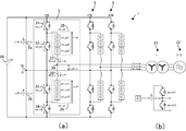
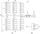
- (A) is a circuit diagram of the power converter device concerning a 1st embodiment
- (b) is a circuit diagram of a chopper cell.
- It is an internal block diagram of the control part of the power converter device concerning a 1st embodiment.
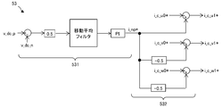
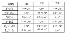
- It is a schematic diagram which shows the control structure of a neutral point electric potential control part. It is a table
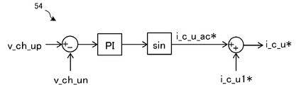
- It is a schematic diagram which shows the control structure of the capacitor voltage balance control part between arms.
- It is a schematic diagram which shows the control structure of a chopper cell group output voltage command value production
- FIG. 1 It is a schematic diagram which shows the control structure of an individual capacitor voltage balance control part. It is a figure for demonstrating the voltage output method of a chopper cell.
- A is a figure for demonstrating the conventional MMC
- (b) is a circuit diagram of a chopper cell.
- FIG. 1 is a circuit diagram of the power conversion device of this embodiment
- FIG. 2 is a block diagram of the internal configuration of the control unit of the power conversion device of this embodiment.
- the power conversion device 1 of this embodiment is connected to a DC power supply 20, converts an input DC voltage v_dc into a three-phase AC voltage v_ac, and supplies power via a three-phase transformer 21. AC power is output to the system 22.
- the power conversion apparatus 1 is connected in parallel with a DC power supply 20, and capacitors 2 a and 2 b connected in series to divide the input DC voltage v_dc to create a neutral point potential, in parallel with the DC power supply 20.
- the U-phase, V-phase, and W-phase leg 3 including the chopper cell C that is connected to each other and serves as a unit converter for converting the direct current of the direct current power source 20 into alternating current, and the output voltage of the chopper cell C of each leg 3 are balanced. Therefore, a control unit 5 that controls the circulating current that flows in the leg 3 of each phase is provided.
- the U phase will be described as a representative as appropriate. Further, it is assumed that the following current and voltage are detected by a current detector and a voltage detector (not shown), and the detected values can be input to the control unit 5.
- the power conversion device 1 turns on the switches 31 and 33 and turns on the DC positive terminal in the U-phase leg 3.
- -Switch 31-Chopper cell group circuit 35-Chopper cell group circuit 36-Switch 33-U-phase circulating current that forms a path of DC neutral point N and makes the voltage of the chopper cell C of the chopper cell group circuits 35 and 36 constant from the capacitor 2a Is supplied.
- the switches 32 and 34 are turned on to form a DC neutral point N-switch 32-chopper cell group circuit 35-chopper cell group circuit 36-switch 34-DC negative terminal path.
- the V-phase circulating current and the W-phase circulating current that make the voltage of the chopper cell C of the chopper cell group circuits 35 and 36 constant are supplied from the capacitor 2b.
- the control unit 5 controls the capacitors 2a and 2b to superimpose a neutral point current that keeps the neutral point potential constant on the circulating current of each phase, whereby the potential at the DC neutral point N is superimposed. Is controlled to be constant.
- a neutral point current i is superimposed on the U-phase leg 3 to discharge excess power of the high-voltage capacitor 2a in order to balance the voltage. Shed.
- ⁇ (1 ⁇ 2) i is superimposed in the V-phase leg 3 and the W-phase leg 3 so that the neutral point current i in excess is charged in the low-voltage capacitor 2b. In this way, the capacitors 2a and 2b are balanced, and the neutral point potential is controlled to be constant.
- Capacitors 2 a and 2 b are DC capacitors, connected in series with each other, and arranged in parallel between the positive terminal and the negative terminal of DC power supply 20.
- a DC neutral point N is formed between the capacitors 2a and 2b.
- the reference potential in the present embodiment is a potential at a DC neutral point N created by dividing the input DC voltage v_dc by the capacitors 2a and 2b, and the neutral point potential is approximately 1 ⁇ 2 of the input DC voltage v_dc.
- the capacitor 2a may be referred to as a positive side capacitor 2a and the capacitor 2b may be referred to as a negative side capacitor 2b with reference to the DC neutral point N.
- Capacitors 2a and 2b have smaller capacities than capacitors of chopper cell C described later.
- Each phase leg 3 is connected in parallel with the DC power source 20. Since any leg 3 has the same configuration, the configuration of the U-phase leg 3 will be described as an example.
- the U-phase leg 3 includes switches 31 to 34, chopper cell group circuits 35 and 36 each including a chopper cell C for converting direct current to alternating current, and reactors 37 and 38.
- the switches 31 to 34 are reverse conducting switches composed of a switching element having a self-extinguishing capability such as an IGBT or a MOSFET that allows current to flow in one direction when turned on, and a feedback diode connected in reverse parallel to the switching element. is there.
- the withstand voltages of the switches 31 to 34 are determined by the input DC voltage v_dc of the DC power supply 20.
- the element to be used is determined in consideration of the superposition of the surge voltage at the time of switching to the voltage of v_dc / 2 with respect to the input DC voltage v_dc.
- one element is included for one switch, but a plurality of elements in series with one switch are also referred to as switches 31 to 34.
- the switches 31 to 34 are connected in series between the DC positive terminal and the DC negative terminal in this order.
- the collector (C) of the switch 31 is connected to the DC positive terminal, and the emitter (E) of the switch 34 is connected to the DC negative terminal.
- the emitter (E) of the switch 32 and the collector (C) of the switch 33 are connected to a DC neutral point N divided by the capacitors 2a and 2b.
- a DC circulating current path is formed by turning on and off the switches 31-34.
- the chopper cell group circuits 35 and 36 are configured by connecting N (N ⁇ 1) chopper cells C in series, and convert the DC voltage into a stepped AC voltage using the chopper cell C as a unit converter.
- the chopper cell C is formed by connecting a leg in which switches sw_ch1 and sw_ch2 are connected in series and a DC capacitor c_ch in parallel.
- the configuration of the switches sw_ch1 and sw_ch2 is the same as the configuration of the switches 31 to 34 described above.
- the chopper cell C outputs the voltage v_ch of the DC capacitor c_ch when the switch sw_ch1 is on, and becomes zero voltage when the switch sw_ch2 is on.
- the number of chopper cells C in the chopper cell group circuits 35 and 36 is determined by the input DC voltage v_dc and the chopper cell capacitor voltage v_ch, and is approximately (v_dc / 2) / v_ch. In the present embodiment, the number of chopper cells C is three.
- the positive terminal of the chopper cell group circuit 35 is connected to the collector (C) of the switch 32, and the negative terminal of the chopper cell group circuit 36 is connected to the emitter (E) of the switch 33.
- the negative terminal of the chopper cell group circuit 35 is connected to the output AC voltage terminal via the reactor 37, and the positive terminal of the chopper cell group circuit 36 is connected to the output AC voltage terminal via the reactor 38.
- the chopper cell group circuit 35 is a positive arm connected to the positive side when viewed from the DC side, and may be referred to as an upper arm.
- the chopper cell group circuit 36 is a negative arm connected to the negative side when viewed from the DC side, and may be referred to as a lower arm.
- a reactor 37 is inserted between the chopper cell group circuit 35 and the output AC voltage terminal 39, and a reactor 38 is inserted between the chopper cell group circuit 36 and the output AC voltage terminal 39. ing.
- the control unit 5 controls the circulating current that flows in the leg 3 of each phase in order to make the output voltage of each chopper cell C constant. Therefore, a command to turn on or off is output to the switches 31 to 34 of each phase leg 3 and the switches sw_ch1 and sw_ch2 of the chopper cell C.
- the control unit 5 includes each phase output voltage control unit 51, each phase capacitor voltage balance control unit 52, and a neutral point potential control unit realized by software processing of a computer equipped with a CPU or the like. 53, an inter-arm capacitor voltage balance control unit 54, a circulating current ACR unit 55, a chopper cell group output voltage command value generation unit 56, and an individual capacitor voltage balance control unit 57 are provided.
- the three-phase / DQ conversion unit 511 performs three-phase / DQ conversion on the calculated i_u, i_v, i_w, calculates the D-axis current i_d and the Q-axis current i_q, and outputs them to the ACR unit 512.
- the ACR unit 512 receives the D-axis current i_d, the Q-axis current i_q, and the D-axis current command value i_d * and the Q-axis current command value i_q *, and the D-axis current i_d and the Q-axis current i_q are PI control is performed so as to follow the command value i_d * and the Q-axis current command value i_q *, and the D-axis voltage command value v_d * and the Q-axis voltage command value v_q * are calculated and output to the DQ / 3-phase converter 513. To do.
- the DQ / 3-phase conversion unit 513 performs DQ / 3-phase conversion on the input D-axis voltage command value v_d * and Q-axis voltage command value v_q *, and voltage command values v_u *, v_v *, v_w of each phase. * Is calculated.
- Each phase capacitor voltage balance control unit 52 performs control to keep the average value of the chopper cell group circuits 35 and 36 of each phase constant. Therefore, the U phase will be described as an example.
- the switches 31 and 33 are turned on, and the DC positive terminal—the switch 31—the chopper cell group circuit 35—the chopper cell group circuit 36.
- -A switch 33-a DC circulating current flows through the path of the DC neutral point N.
- the PI control is performed so as to follow the desired command value, and the circulating current command value i_c_u0 * is calculated.
- the same control is performed for the V phase and the W phase, and each phase capacitor voltage control unit 52 outputs the obtained circulating current command values i_c_u0 *, i_c_v0 *, i_c_w0 * of the respective phases to the neutral point potential control unit 53. To do.
- the neutral point potential control unit 53 controls the neutral point potential of the DC neutral point N to be constant.
- the neutral point voltage is kept constant by intentionally flowing the current i_np into the neutral point potential.
- the neutral point current command value i_np * is superimposed on the DC circulating current of each phase.
- the neutral point potential control unit 53 includes a neutral point current command value calculation unit 531 and a neutral point current superimposition unit 532, as shown in FIG.
- the neutral point current command value calculation unit 531 receives the input of the voltage v_dc_p of the capacitor 2a and the voltage v_dc_n of the capacitor 2b, calculates a difference voltage between them, and multiplies it by 1/2. Further, the neutral point current command value i_np * is calculated by passing the moving average filter and performing PI control so that the differential voltage follows zero.
- the reason why the difference voltage is halved is that, for example, when the voltage v_dc_p of the capacitor 2a increases, the voltage v_dc_n of the capacitor 2b decreases correspondingly, so that the increased amount can be accurately obtained.
- the moving average filter is provided in order to eliminate the influence on the control. That is, in the three-phase NPC-MMC, the neutral point potential is three times the AC voltage frequency because the current supplied by the positive capacitor 2a and the negative capacitor 2b fluctuates at a frequency three times the AC voltage frequency. Fluctuates. Such harmonic components are included in the voltage difference between the capacitors 2a and 2b, and a moving average is taken in order to eliminate the influence on control such as hunting.
- the moving average cycle is more than the number of legs of the output AC voltage cycle (three times here), so that the influence on the control can be further eliminated.
- harmonic components may be removed by a low-pass filter instead of the moving average filter.
- Increasing the gain means, for example, increasing the gain higher than the gain used in the PI control when at least one of the filters is inserted.
- the neutral point current superimposing unit 532 superimposes the neutral point current command value i_np * obtained by the neutral point current command value calculating unit 531 on the circulating current command value of each phase.
- the U-phase AC voltage is positive, and the V-phase and W-phase AC voltages are negative. Therefore, the U-phase circulating current is supplied from the positive capacitor 2a, and the V and W-phase circulating currents are supplied from the negative capacitor 2b.
- i_np * is added to the U-phase circulating current command value i_c_u0 *, and the V and W-phase circulating current command values i_c_v0 *, i_np * / 2 is distributed and subtracted from i_c_w0 *.
- the circulating current command values i_c_u1 *, i_c_v1 *, i_c_w1 * for each phase for making the neutral point potential constant are calculated.
- the neutral point voltage can be made constant by the same control method.
- the neutral point potential control unit 53 outputs the circulating current command values i_c_u1 *, i_c_v1 *, i_c_w1 * of each phase for making the obtained neutral point potential constant to the inter-arm capacitor voltage control unit 54.
- the inter-arm capacitor voltage balance control unit 54 makes the capacitor voltage average value v_ch_up of the chopper cell group circuit 35 and the capacitor voltage average value v_ch_un of the chopper cell group circuit 36 the same. To realize this, when the output AC voltage is larger than the DC neutral point voltage, the output is made to the path of DC positive terminal-switch 31-chopper cell group circuit 35-chopper cell group circuit 36-switch 33-DC neutral point N. An AC circulating current with the same frequency as the AC voltage is applied. When the output AC voltage is smaller than the DC neutral point voltage, the DC neutral point N-switch 32-chopper cell group circuit 35-chopper cell group circuit 36-switch 34-DC negative terminal has the same frequency as the output AC voltage. Apply AC circulating current.
- the capacitor voltage average value v_ch_up of the upper arm 35 and the capacitor voltage average value v_ch_un of the lower arm 36 are received, and the value obtained by subtracting v_ch_un from v_ch_up and substituting the value for proportional integration control is substituted into the sine function.
- the obtained value is set as an AC circulating current command value i_c_ac *.
- the U-phase circulating current command value i_c_u * is calculated by adding this and the U-phase circulating current command value i_c_u1 * for making the neutral point potential constant. Therefore, the U-phase circulating current command value i_c_u * is obtained by adding the AC circulating current to the DC circulating current.
- the inter-arm capacitor voltage control unit 54 calculates the circulating current command values for the V phase and the W phase, and outputs the calculated phase circulating current command values i_c_u *, i_c_v *, i_c_w * to the circulating current ACR unit 55. To do.
- the circulating current ACR unit 55 performs proportional-integral control so that the U-phase circulating current i_c_u follows the input U-phase circulating current command value i_c_u *, and generates a U-phase circulating voltage command value v_c_u *. Similarly, the circulating current ACR 55 is generated for the V phase and the W phase, and the circulating voltage command values v_c_u *, v_c_v *, and v_c_w * of each phase are output to the chopper cell group output voltage command value generation unit 56.
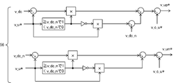
- the chopper cell group output voltage command value generation unit 56 generates voltage command values output from the chopper cell group circuits 35 and 36.
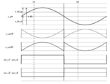
- FIG. 6 by taking the U phase as an example, when the AC voltage command value v_u * is greater than the DC neutral point voltage v_dc_n, as shown at timing t1 in FIG. Turn off.
- the chopper cell group circuit 35 outputs a difference voltage between the input DC voltage v_dc and the output AC voltage v_ac_u
- the chopper cell group circuit 36 outputs a difference voltage between the output AC voltage v_ac_u and the DC neutral point voltage v_dc_n.
- the switches 32 and 34 are turned on and the switches 31 and 33 are turned off.
- the chopper cell group circuit 35 outputs a difference voltage between the DC neutral point voltage v_dc_n and the output AC voltage v_ac_u
- the chopper cell group circuit 36 outputs a difference voltage between the output AC voltage v_ac_u and the DC negative voltage.
- v_up * v_dc_n ⁇ v_u * ⁇ v_c_u *.
- v_un * v_u * ⁇ v_c_u *.
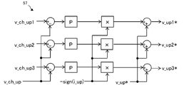
- the individual capacitor voltage balance control unit 57 adjusts the output voltages of the chopper cells C of the chopper cell group circuits 35 and 36 to be the same. That is, since the capacitor is charged when the U-phase upper arm current i_up is positive, the output voltage of the chopper cell C having a small capacitor voltage is increased, and the output voltage of the chopper cell C having a large capacitor voltage is decreased. Since the capacitor is discharged when the U-phase upper arm current i_up is negative, the output voltage of the chopper cell C having a small capacitor voltage is decreased, and the output voltage of the chopper cell C having a large capacitor voltage is increased.
- the individual capacitor voltage balance control unit 57 will be described by taking the U-phase chopper cell group circuit 35 as an example.
- the capacitor voltage of the chopper cell group circuit 35 is obtained from the capacitor voltage v_ch_up1.
- the value obtained by subtracting the voltage average value v_ch_up and multiplying this by the proportional gain is multiplied by a value ⁇ sign (i_up) obtained by inverting the sign of the U-phase arm current i_up, and the U-phase arm voltage command value v_up * is added.
- the voltage command values v_up1 *, v_up2 *, and v_up3 * of each chopper cell are calculated.
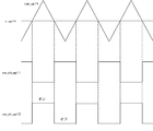
- a chopper cell ch_up1 will be described as an example with reference to FIG. Note that the two switches constituting the chopper cell ch_up1 are sw_ch_up11 and sw_ch_up12.
- the switch sw_ch_up11 is turned on and the sw_ch_up12 is turned off.
- the switch sw_ch_up11 is turned off and the sw_ch_up12 is turned on.
- the equivalent carrier frequency can be increased to N times the carrier triangular wave frequency by shifting the phase of the carrier triangular wave by 360 ° / N, and each switch can be turned on and off more. Do it finely. Therefore, the harmonic voltage of the output AC voltage can be reduced and the output AC voltage can be made smooth. Further, by making the carrier triangular wave phase used for the chopper cell group circuit 36 the same as that of the chopper cell group circuit 35, the harmonic voltage of the output AC voltage can be further reduced.
- the power conversion device 1 of the present embodiment is a power conversion device that converts power between alternating current and direct current, and is connected in parallel with the direct current power source 20 to divide the input direct current voltage of the direct current power source 20.
- Capacitors 2a and 2b connected in series for generating a neutral point potential, a plurality of legs 3 each connected in parallel with a DC power supply 20 and including a chopper cell C for converting DC to AC, and a leg for each phase 3 to control the circulating current that flows in the leg 3 of each phase in order to balance the output voltage of the three chopper cells, and the control unit 5
- a neutral point potential control unit 53 for superimposing a neutral point current for controlling the neutral point potential to be constant is provided, and the neutral point potential control unit 53 is connected to at least one of the capacitors 2a and 2b. Circulated current superimposed on
- the neutral point clamp type power converter that can keep the neutral point potential constant.
- a method of applying a zero-phase voltage is also conceivable, but in this case, the control response speed depends on the frequency of the output AC voltage, resulting in neutral point potential fluctuations. There is a risk of increasing the DC capacitor capacity.
- the neutral point current can be flowed at any time during one period, so that a control response speed independent of the frequency of the output AC voltage can be realized.
- the leg 3 includes multiple switches 31 to 34 connected in series and a pair of chopper cell group circuits 35 and 36 in which one or more chopper cells C are connected in series. In this order, it is provided between a DC positive terminal and a DC negative terminal connected to the DC power supply 20, and is connected to the DC neutral point N between the switch 32 and the switch 33. 32 and 33 are connected in parallel.
- the number of chopper cells can be reduced to half, and the size of the power converter can be reduced.
- the DC capacitor capacity is smaller than that of the chopper cell, and the size of the power converter can be reduced.
- switching loss can be reduced and conversion efficiency can be improved by reducing the number of chopper cells.
- the neutral point potential control unit 53 charges the low-voltage capacitor with the power discharged from the high-voltage capacitor among the capacitors 2a and 2b. Thereby, it is possible to easily control the neutral point potential to be constant. For example, when the positive side capacitor 2a has a high voltage and the negative side capacitor 2b has a low voltage, the discharge current of the positive side capacitor 2a is charged to the negative side capacitor 2b via the other two-phase leg 3, and the capacitor 2a , 2b, it is easier to keep the neutral point potential constant by controlling both capacitors 2a, 2b.
- the neutral point potential control unit 53 distributes and superimposes the neutral point current to the leg 3 of each phase.
- the neutral point current to be superimposed is distributed to the leg 3 of each phase, so that it is possible to reduce a burden such as a thermal burden accompanying an increase in the current flowing through the switches 31 to 34.
- a burden such as a thermal burden accompanying an increase in the current flowing through the switches 31 to 34.
- a neutral point current is allowed to flow only in the U-phase leg 3
- the positive capacitor 2 a is discharged and charged in the capacitor of the chopper cell group circuit 35, and the V-phase and W-phase leg 3 is charged.
- the burden can be distributed to each phase leg 3.
- the neutral point potential control unit 53 calculates the neutral point current command value i_np * by proportional-integral control of the voltage difference between the capacitors 2a and 2b. Thereby, the voltages of the capacitors 2a and 2b become the same, and the neutral point potential can be controlled to be constant.
- the neutral point potential control unit 53 includes a low-pass filter that removes a high-frequency component included in the voltage difference between the capacitors 2a and 2b. As a result, a stable neutral point current command value can be generated, so that it is possible to eliminate the influence on control due to having a high-frequency component.
- the neutral point potential control unit 53 has a moving average filter that removes high frequency components included in the voltage difference between the capacitors 2a and 2b. As a result, a stable neutral point current command value can be generated, so that it is possible to eliminate the influence on control due to having a high-frequency component.
- the moving average period of the moving average filter is set to be not less than the number of legs of the output AC voltage period.
- the neutral point potential is formed by the two capacitors 2a and 2b.
- the neutral point potential is determined by a capacitor connected in series on the positive side and a capacitor connected in series on the negative side. You may make it form. Thereby, a withstand voltage can be enlarged. Further, two or more capacitors may be connected in parallel to each of the capacitors 2a and 2b to increase the capacitor capacity.
- the three-phase legs 3 are connected in parallel to the two capacitors 2a and 2b connected in series.
- the two capacitors 2a connected in series to the leg 3 in each phase are connected.
- 2b may be connected in parallel most recently.
Landscapes
- Engineering & Computer Science (AREA)
- Power Engineering (AREA)
- Inverter Devices (AREA)
Abstract
Dispositif de conversion de puissance capable de maintenir constant un potentiel de neutre. Ledit dispositif de conversion de puissance, qui convertit une puissance entre courant alternatif et courant continu, comporte: des condensateurs 2a, 2b branchés en série qui sont branchés en parallèle avec une alimentation 20 à courant continu et divisent une tension continue d'entrée provenant de celle-ci de façon à créer un potentiel de neutre; une pluralité de branches 3 dont chacune est branchée en parallèle avec l'alimentation 20 à courant continu et qui contiennent des cellules hacheuses C servant à convertir un courant continu en courant alternatif; et une unité de régulation qui régule des courants circulants qui sont amenés à circuler à travers les branches 3 pour les phases respectives afin d'équilibrer les tensions de sortie des cellules hacheuses dans les branches 3 respectives. L'unité de régulation contient une unité de régulation du potentiel de neutre qui superpose au courant circulant continu amené à circuler entre des bornes à courant continu pour chaque phase, un courant de neutre servant à maintenir constant le potentiel de neutre susmentionné. Ladite unité de régulation du potentiel de neutre fait en sorte qu'au moins un des condensateurs 2a, 2b susmentionnés fasse circuler les courants circulants auxquels sont superposés les courants de neutre susmentionnés.
Priority Applications (2)
| Application Number | Priority Date | Filing Date | Title |
|---|---|---|---|
| EP15836708.6A EP3188356A4 (fr) | 2014-08-25 | 2015-07-21 | Dispositif de conversion de puissance |
| CN201580045581.3A CN106575929B (zh) | 2014-08-25 | 2015-07-21 | 功率转换装置 |
Applications Claiming Priority (2)
| Application Number | Priority Date | Filing Date | Title |
|---|---|---|---|
| JP2014170804A JP6253548B2 (ja) | 2014-08-25 | 2014-08-25 | 電力変換装置 |
| JP2014-170804 | 2014-08-25 |
Publications (1)
| Publication Number | Publication Date |
|---|---|
| WO2016031430A1 true WO2016031430A1 (fr) | 2016-03-03 |
Family
ID=55399331
Family Applications (1)
| Application Number | Title | Priority Date | Filing Date |
|---|---|---|---|
| PCT/JP2015/070665 Ceased WO2016031430A1 (fr) | 2014-08-25 | 2015-07-21 | Dispositif de conversion de puissance |
Country Status (4)
| Country | Link |
|---|---|
| EP (1) | EP3188356A4 (fr) |
| JP (1) | JP6253548B2 (fr) |
| CN (1) | CN106575929B (fr) |
| WO (1) | WO2016031430A1 (fr) |
Cited By (2)
| Publication number | Priority date | Publication date | Assignee | Title |
|---|---|---|---|---|
| EP3432461A4 (fr) * | 2016-03-15 | 2019-11-13 | Kabushiki Kaisha Toshiba | Dispositif de conversion de puissance |
| CN113759181A (zh) * | 2020-06-01 | 2021-12-07 | 台达电子工业股份有限公司 | 直流链电容电压不平衡的检测装置 |
Families Citing this family (5)
| Publication number | Priority date | Publication date | Assignee | Title |
|---|---|---|---|---|
| JP6502870B2 (ja) * | 2016-02-04 | 2019-04-17 | 株式会社東芝 | 電力変換装置 |
| JP6957196B2 (ja) * | 2017-05-17 | 2021-11-02 | 株式会社東芝 | 電力変換装置 |
| US12212251B2 (en) * | 2020-03-30 | 2025-01-28 | Mitsubishi Electric Corporation | Power conversion device having converter cells connected in series in a multiplexed manner and each including an energy storage element |
| JP2023167438A (ja) * | 2022-05-12 | 2023-11-24 | 富士電機株式会社 | 電力変換装置 |
| WO2024236648A1 (fr) * | 2023-05-12 | 2024-11-21 | 株式会社Subaru | Dispositif de charge pour véhicule électrique |
Citations (3)
| Publication number | Priority date | Publication date | Assignee | Title |
|---|---|---|---|---|
| JP2013099054A (ja) * | 2011-10-31 | 2013-05-20 | Hitachi Ltd | 電力変換装置 |
| JP2013143836A (ja) * | 2012-01-11 | 2013-07-22 | Toshiba Mitsubishi-Electric Industrial System Corp | 3レベル電力変換装置 |
| JP2014096969A (ja) * | 2012-11-12 | 2014-05-22 | Hitachi Ltd | 電力変換装置及び電力変換方法 |
Family Cites Families (5)
| Publication number | Priority date | Publication date | Assignee | Title |
|---|---|---|---|---|
| US8228695B2 (en) * | 2009-11-16 | 2012-07-24 | General Electric Company | Multilevel converter operation |
| US8441820B2 (en) * | 2010-09-29 | 2013-05-14 | General Electric Company | DC-link voltage balancing system and method for multilevel converters |
| US9559611B2 (en) * | 2012-09-28 | 2017-01-31 | General Electric Company | Multilevel power converter system and method |
| US9479075B2 (en) * | 2013-07-31 | 2016-10-25 | General Electric Company | Multilevel converter system |
| JP6219188B2 (ja) * | 2014-02-03 | 2017-10-25 | 株式会社東芝 | 電力変換装置 |
-
2014
- 2014-08-25 JP JP2014170804A patent/JP6253548B2/ja not_active Expired - Fee Related
-
2015
- 2015-07-21 WO PCT/JP2015/070665 patent/WO2016031430A1/fr not_active Ceased
- 2015-07-21 CN CN201580045581.3A patent/CN106575929B/zh active Active
- 2015-07-21 EP EP15836708.6A patent/EP3188356A4/fr not_active Withdrawn
Patent Citations (3)
| Publication number | Priority date | Publication date | Assignee | Title |
|---|---|---|---|---|
| JP2013099054A (ja) * | 2011-10-31 | 2013-05-20 | Hitachi Ltd | 電力変換装置 |
| JP2013143836A (ja) * | 2012-01-11 | 2013-07-22 | Toshiba Mitsubishi-Electric Industrial System Corp | 3レベル電力変換装置 |
| JP2014096969A (ja) * | 2012-11-12 | 2014-05-22 | Hitachi Ltd | 電力変換装置及び電力変換方法 |
Non-Patent Citations (1)
| Title |
|---|
| See also references of EP3188356A4 * |
Cited By (2)
| Publication number | Priority date | Publication date | Assignee | Title |
|---|---|---|---|---|
| EP3432461A4 (fr) * | 2016-03-15 | 2019-11-13 | Kabushiki Kaisha Toshiba | Dispositif de conversion de puissance |
| CN113759181A (zh) * | 2020-06-01 | 2021-12-07 | 台达电子工业股份有限公司 | 直流链电容电压不平衡的检测装置 |
Also Published As
| Publication number | Publication date |
|---|---|
| JP2016046955A (ja) | 2016-04-04 |
| EP3188356A1 (fr) | 2017-07-05 |
| CN106575929B (zh) | 2019-09-24 |
| JP6253548B2 (ja) | 2017-12-27 |
| CN106575929A (zh) | 2017-04-19 |
| EP3188356A4 (fr) | 2018-04-25 |
Similar Documents
| Publication | Publication Date | Title |
|---|---|---|
| JP6253548B2 (ja) | 電力変換装置 | |
| Babaei et al. | Symmetric and asymmetric multilevel inverter topologies with reduced switching devices | |
| EP2491644B1 (fr) | Système et procédé permettant de compenser un déséquilibre de tension d'entrée dans des onduleurs à multiniveaux ou analogues | |
| CN102577066B (zh) | 带无功功率补偿的变换器 | |
| JP6219188B2 (ja) | 電力変換装置 | |
| US9960709B2 (en) | Power conversion device | |
| CN102388517A (zh) | 用于交换电力的装置 | |
| JP6494378B2 (ja) | 電力変換システムおよび電力変換システムの制御方法 | |
| US9755551B2 (en) | Power conversion device | |
| JP2018196237A (ja) | 電力変換装置 | |
| JPWO2017046910A1 (ja) | 電力変換装置 | |
| JP2018129963A (ja) | 電力変換器の制御装置 | |
| JP6524000B2 (ja) | 電力変換装置 | |
| JP6502870B2 (ja) | 電力変換装置 | |
| Gleissner et al. | Operation of fault-tolerant inverters with DC-link midpoint connection for adjustable speed drives | |
| Itoh et al. | Experimental verification of a multi-level inverter with H-bridge clamp circuit for single-phase three-wire grid connection | |
| Singh et al. | An Optimized Half Bridge Type Single-Phase 5-level Switched Capacitor Inverter with Charging State Availability in Each Switching Period | |
| Liu et al. | A direct power conversion topology for grid integrations of hybrid AC/DC resources | |
| Plyusnin | Multilevel modular converters for off-shore wind farm HVDC transmission system |
Legal Events
| Date | Code | Title | Description |
|---|---|---|---|
| 121 | Ep: the epo has been informed by wipo that ep was designated in this application |
Ref document number: 15836708 Country of ref document: EP Kind code of ref document: A1 |
|
| NENP | Non-entry into the national phase |
Ref country code: DE |
|
| REEP | Request for entry into the european phase |
Ref document number: 2015836708 Country of ref document: EP |
|
| WWE | Wipo information: entry into national phase |
Ref document number: 2015836708 Country of ref document: EP |