WO2016035191A1 - Machine électrique tournante et procédé de fabrication d'un noyau de rotor - Google Patents
Machine électrique tournante et procédé de fabrication d'un noyau de rotor Download PDFInfo
- Publication number
- WO2016035191A1 WO2016035191A1 PCT/JP2014/073360 JP2014073360W WO2016035191A1 WO 2016035191 A1 WO2016035191 A1 WO 2016035191A1 JP 2014073360 W JP2014073360 W JP 2014073360W WO 2016035191 A1 WO2016035191 A1 WO 2016035191A1
- Authority
- WO
- WIPO (PCT)
- Prior art keywords
- rotor core
- electrical machine
- rotating electrical
- teeth
- core
- Prior art date
- Legal status (The legal status is an assumption and is not a legal conclusion. Google has not performed a legal analysis and makes no representation as to the accuracy of the status listed.)
- Ceased
Links
Images







Classifications
-
- H—ELECTRICITY
- H02—GENERATION; CONVERSION OR DISTRIBUTION OF ELECTRIC POWER
- H02K—DYNAMO-ELECTRIC MACHINES
- H02K1/00—Details of the magnetic circuit
- H02K1/06—Details of the magnetic circuit characterised by the shape, form or construction
- H02K1/22—Rotating parts of the magnetic circuit
-
- H—ELECTRICITY
- H02—GENERATION; CONVERSION OR DISTRIBUTION OF ELECTRIC POWER
- H02K—DYNAMO-ELECTRIC MACHINES
- H02K1/00—Details of the magnetic circuit
- H02K1/06—Details of the magnetic circuit characterised by the shape, form or construction
- H02K1/22—Rotating parts of the magnetic circuit
- H02K1/27—Rotor cores with permanent magnets
-
- H—ELECTRICITY
- H02—GENERATION; CONVERSION OR DISTRIBUTION OF ELECTRIC POWER
- H02K—DYNAMO-ELECTRIC MACHINES
- H02K15/00—Processes or apparatus specially adapted for manufacturing, assembling, maintaining or repairing of dynamo-electric machines
- H02K15/02—Processes or apparatus specially adapted for manufacturing, assembling, maintaining or repairing of dynamo-electric machines of stator or rotor bodies
Definitions
- the disclosed embodiment relates to a method of manufacturing a rotating electrical machine and a rotor core.
- Patent Document 1 describes a rotating electrical machine including a rotor core in which steel plates made of carbon steel or alloy steel having hardenability are stacked and the periphery of a magnet mounting hole is quenched. As a result, the rotor core is made strong and high speed rotation is realized. Also, in this rotating electrical machine, the rotor core is intentionally saturated by concentrating the magnetic flux generated from the magnet on the rotor surface, and the change in magnetic flux density near the rotating rotor core surface is reduced. The iron loss is kept low and high efficiency is achieved.
- the present invention has been made in view of such problems, and an object of the present invention is to provide a rotating electrical machine and a method of manufacturing a rotor core capable of increasing efficiency.
- a rotor core including a stator core and a plurality of stacked steel plates, the axial dimension of which is shorter than the stator core, and the rotor core And a permanent magnet having an axial dimension shorter than that of the rotor core is applied.
- a method for manufacturing a rotor core of a rotating electrical machine in which a heat-treated steel sheet is stamped and formed into a desired shape, and a plurality of the formed steel sheets are laminated.
- a method for manufacturing a rotor core which includes bonding an oxide film formed on the surface of the steel sheet by the heat treatment with an adhesive.
- the rotating electrical machine 1 has a stator 2 and a rotor 3.
- the stator 2 is provided on the inner periphery of the cylindrical frame 4.
- the rotor 3 is provided on the outer periphery of the shaft 10 and is disposed so as to face the stator 2 in the radial direction.
- a load side bracket 5 is provided on the load side (right side in FIG. 1) of the frame 4, and an antiload side bracket 6 is provided on the antiload side (left side in FIG. 1) of the frame 4.
- the shaft 10 is rotatably supported by a load side bearing 7 provided on the load side bracket 5 and an antiload side bearing 8 provided on the antiload side bracket 6.
- An encoder 9 that detects the rotational position of the shaft 10 is provided at the end of the shaft 10 on the side opposite to the load. Note that the encoder 9 may not be provided.
- a bush 12 into which a lead wire 11 connected to an external power source (not shown) is inserted is attached to the outer periphery of the non-load side bracket 6.
- the lead wire 11 is connected to a connection portion (not shown) in which a plurality of stator windings 25 of the stator 2 are connected on the opposite load side of the stator 2.
- the “load side” refers to the direction in which a load is attached to the rotating electrical machine 1, that is, the direction in which the shaft 10 protrudes (right side in FIG. 1) in this example.
- the direction opposite to the load side that is, the direction in which the encoder 9 is arranged with respect to the rotating electrical machine 1 in this example (left side in FIG. 1) is indicated.
- the stator 2 includes a stator core 21 and a plurality (12 in the illustrated example) of the stator windings 25.
- the stator core 21 has a cylindrical outer stator core portion 22 provided along the inner peripheral surface of the frame 4 and an inner stator core portion 23 provided inside the outer stator core portion 22.
- the inner stator core portion 23 includes a plurality (12 in the illustrated example) of teeth 23b arranged radially, and a connecting portion 23a that connects end portions on the inner peripheral side of the plurality of teeth 23b in a cylindrical shape.
- the outer stator core portion 22 and the inner stator core portion 23 are fixed by bolts 24 penetrating the outer peripheral end portions of the teeth 23 b of the inner stator core portion 23 and the outer stator core portion 22.
- Each stator winding 25 is wound around the teeth 23b of the inner stator core portion 23, and is formed between a plurality of teeth 23b adjacent to the circumferential direction and the outer stator core portion 22 (in the illustrated example). 12) in the slot 26.
- the rotor 3 includes a cylindrical rotor core 31 disposed with a magnetic gap inside the stator 2, and a plurality of rotor cores 31 provided inside the rotor core 31. And 20 permanent magnets 32 (in the illustrated example).
- the axial dimension Lr of the rotor core 31 is shorter by a predetermined length than the axial dimension Ls of the stator core 21, and the axial dimension Lm of the permanent magnet 32 is equal to the rotor core 31.
- the predetermined length is set shorter than the axial dimension Lr.
- IPM Internal Permanent Magnet
- the rotor core 31 has a hole 36 provided with a plurality of convex portions 36a on the inner peripheral surface.
- the shaft 10 has a plurality of recesses 10a on the outer peripheral surface of the rotor mounting portion.
- the rotor core 31 is fixed to the outer peripheral surface of the shaft 10 by being fitted to the shaft 10 by shrink fitting or the like while fitting the convex portion 36a and the concave portion 10a. Further, between the load side bearing 7 and the end surface of the rotor core 31, and between the anti-load side bearing 8 and the end surface of the rotor core 31, the load side plate 15 and the anti load side plate 16 are respectively connected to the shaft 10. It is fixed to.
- the rotor core 31 is restricted from moving in the axial direction by the load side plate 15 and the anti-load side plate 16.
- the rotor core 31 includes a plurality of magnet mounting holes 33 into which the plurality of permanent magnets 32 are inserted.
- each magnet mounting hole 33 is provided so as to penetrate the rotor core 31 along the axial direction.
- each magnet mounting hole 33 has a substantially rectangular shape when viewed from the axial direction, but the two corners 33a on the outer peripheral side thereof have an arc shape (in other words, a curved surface shape when viewed from the axial direction). ).
- the permanent magnet 32 is formed in a substantially rectangular parallelepiped shape, and the shape seen from the axial direction is a substantially rectangular shape, but the two outer peripheral corners 32a corresponding to the corners 33a of the magnet mounting hole 33 are seen from the axial direction.
- the permanent magnet 32 is inserted into the magnet mounting hole 33 and fixed with an adhesive or the like.
- the curved end surface on the outer peripheral side of the permanent magnet 32 mounted in the magnet mounting hole 33 and the planar side surfaces on both sides in the circumferential direction are curved end surfaces on the outer peripheral side of the magnet mounting hole 33 and the planar end surfaces on both sides in the circumferential direction. Touch the side.
- a gap 33 b is formed between the planar end surface 32 b on the inner peripheral side of the permanent magnet 32 and the end surface on the inner peripheral side of the magnet mounting hole 33.
- the plurality of permanent magnets 32 embedded in the plurality of magnet mounting holes 33 includes two N poles or S poles having the same polarity, as viewed from the axial direction.
- the permanent magnets 32 are arranged in the rotor core 31 in such a manner that the permanent magnets 32 form a V-shaped pair projecting radially inward, and the opposite magnetic poles of the same polarity are alternately varied in the circumferential direction.
- a plurality (ten in this example) of magnetic pole portions 34 of N poles and S poles having different polarities are formed in the circumferential direction of the rotor core 31.
- the angle between the two permanent magnets 32 arranged in a V shape so that the magnetic flux generated from the permanent magnet 32 in each magnetic pole portion 34 is concentrated on the surface of the rotor 3. Is designed to be sufficiently narrow.
- the rotor core 31 between the two permanent magnets 32 is intentionally saturated with magnetic flux, and the change in magnetic flux density in the portion near the surface of the rotating rotor core 31 is reduced. Designed to keep iron loss low.
- the rotor core 31 is formed by laminating a plurality of steel plates 37 punched and formed in a desired shape in the axial direction. Adjacent steel plates 37 are bonded together by an adhesive 38 (see FIG. 5A described later).
- a steel plate having hardenability such as carbon steel and alloy steel is used.
- the entire steel plate 37 is quenched, and the plurality of steel plates 37 are stacked to form the rotor core 31 that is heat-treated on the entire surface including the inside.
- the steel plates that have not been heat-treated may be laminated and then quenched by, for example, high-frequency heating.
- the part to be partially heat-treated includes, for example, a surface portion of the rotor core 31 and a region that is easily broken by stress due to the centrifugal force of the permanent magnet 32. As shown in FIG.
- the region that is easily broken is, for example, a peripheral region 31 a around the outer periphery of the magnet mounting hole 33, a region 31 b between adjacent magnet mounting holes 33 arranged in a V shape, and the like.
- the heat treatment applied to the rotor core 31 is not limited to quenching, and may be annealing (annealing) performed for removing strain due to work hardening, for example.
- the steel plate 37 is not limited to the steel plate which has hardenability, You may use a normal electromagnetic steel plate.
- FIG. 5A shows a rotor core 41 of a comparative example.
- a general electromagnetic steel sheet 47 is laminated.
- the magnetic steel sheet 47 is rolled and annealed in the final step, processed to a prescribed thickness, and then subjected to an insulating film treatment.
- the insulating film 47a thus formed is formed with a thickness sufficient to block the eddy current flowing between the electromagnetic steel sheets 47 (thicker than the oxide film 37a).
- a gap 49 is generated between the adjacent electromagnetic steel sheets 47 according to the flatness of the surface of the steel sheet 47, but insulation is ensured by the insulating coating 47a, so that the gap 49 is not filled with an adhesive or the like.
- the surface of the electromagnetic steel sheet 47 is not oxidized, so that it is heated in a vacuum and slowly cooled. For this reason, since processing time becomes long and the apparatus for evacuating a heating installation etc. are needed, cost may increase.
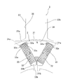
- FIG. 5B shows the rotor core 31 of this embodiment.
- the steel plate 37 has an oxide film 37a formed by quenching on its surface. Since this oxide film 37a is very thin, the insulating property may be low. Therefore, there is a possibility that the insulating property of the oxide film 37a may be impaired at a portion where the steel plate 37 and the steel plate 37 are in contact with each other due to vibration or the like during operation of the rotating electrical machine 1. Therefore, in the present embodiment, the adhesive 38 is filled in the gap 39 generated between the adjacent steel plates 37 due to unevenness (fine irregularities) on the surface of the steel plate 37.
- the adhesive 38 is made of, for example, a resin and has an insulating property.
- This adhesive 38 bonds the oxide films 37a of the adjacent steel plates 37 together.
- the adhesive agent 38 becomes a shock absorbing material, it can suppress the vibration of the steel plates 37, and can maintain the insulation property which is not inferior to the insulating film 40 of the comparative example for a long time.
- the steel plate 37 does not have a final annealing step and is a quenching step, so it does not need to be slowly cooled and may be rapidly cooled.
- the oxide film 37a is intentionally generated, it is not necessary to make the heating equipment vacuum. Furthermore, there is no insulation coating treatment. For this reason, the processing time can be greatly shortened and the cost can be reduced.
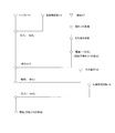
- the adhesive 38 is dropped on the steel plate 37, and the steel plate 37 is rotated at a high speed and bonded by centrifugal force.
- the first method stamp coating
- the second method in which the adhesive 38 is sprayed and applied to the steel plate 37 from a spray nozzle, and the impregnating adhesive as the adhesive 38
- the lower half of the rotor core 31 is immersed in a bath of impregnating adhesive 38 at a shallow depth, and the adhesive 38 is sucked up by capillarity.
- a third method for infiltrating the water is used to infiltrating the water.
- the load side plate 15 is pressed into the shaft 10 and integrated.
- the rotor core 31 is assembled to the shaft 10 integrated with the load side plate 15.
- the permanent magnet 32 is attached to the magnet attachment hole 33 of the rotor core 31 and bonded and integrated.
- the anti-load side plate 16 is press-fitted into the shaft 10 and integrated.
- the permanent magnet 32 is magnetized. Thereby, the rotor 3 is completed.
- the rotating electrical machine 1 includes the stator core 21, the rotor core 31, and the permanent magnet 32.
- the axial dimension Lr of the rotor core 31 is set shorter than the axial dimension Ls of the stator core 21, and the axial dimension Lm of the permanent magnet 32 is set shorter than the axial dimension Lr of the rotor core 31. Yes. Thereby, the following effects are obtained.
- FIG. 7 is a diagram illustrating an example of a general magnetic hysteresis curve.
- stator core 21> rotor core 31> permanent magnet 32 by making the size relationship of the axial direction as follows: stator core 21> rotor core 31> permanent magnet 32, the magnetic path resistance in the portion where there is no tooth 23b can be reduced, and the fluctuation of the magnetic path resistance can be reduced. Can be small. As a result, ⁇ B and ⁇ H in the hysteresis curve of FIG. 7 can be reduced, and the iron loss generated in the rotor core 31 can be reduced. Thereby, since the iron loss (hysteresis loss) which generate
- At least a part of the rotor core 31 is subjected to heat treatment (quenching in the above example).
- quench hardening since the intensity
- the rotor core 31 is configured by laminating steel plates 37 having hardenability and heat-treated.
- each steel plate 37 which comprises the rotor iron core 31 becomes high intensity
- the stator core 21 includes a plurality of teeth 23b around which the stator winding 25 is wound, and a connecting portion 23a that connects the inner peripheral end of the teeth 23b in a cylindrical shape.
- the connecting portion 23a can further reduce the magnetic path resistance in the portion where the tooth 23b is not present (the slot 26 portion), and can further reduce the fluctuation of the magnetic path resistance.
- the iron loss (hysteresis loss) generated in the rotor core 31 can be reduced, the rotating electrical machine 1 can be further improved in efficiency.
- the steel plate 37 has an oxide film 37 a formed by heat treatment on the surface, and the oxide films 37 a of the steel plates 37 adjacent to the rotor core 31 are bonded to each other by an adhesive 38. .
- the oxide film 37a formed on the surface of the steel plate 37 in the quenching process is very thin and may have low insulation. Therefore, there is a possibility that the insulating property of the oxide film 37a may be impaired at a portion where the steel plate 37 and the steel plate 37 are in contact with each other due to vibration or the like during operation of the rotating electrical machine 1. Therefore, by filling the adhesive 38 between the oxide films 37a of the adjacent steel plates 37, vibrations between the steel plates 37 can be suppressed, and deterioration of the rust and the like of the oxide films 37a can be prevented. Thereby, it is possible to maintain the insulating property which is not inferior to the conventional insulating film for a long time. Further, it is not necessary to provide an insulating film on the steel plate 37 as described above. Therefore, since the insulating film treatment is unnecessary, the processing time can be greatly shortened and the cost can be reduced.
- the rotor core 31 is provided with a magnet mounting hole 33 in which the outer corner 33 a has an arc shape, and the permanent magnet 32 corresponds to the corner 33 a of the magnet mounting hole 33.
- the corner 32a is formed in an arc shape.
- the manufacturing method of the rotor core 31 of the rotary electric machine 1 includes a step of stamping and forming the quenched steel plate 37 into a desired shape, a step of laminating the plurality of formed steel plates 37, and quenching. A step of bonding the oxide films 37a formed on the surface of the steel plate 37 by the treatment with an adhesive 38.
- a general electrical steel sheet used for a rotor core is rolled and annealed in the final process, processed to a specified thickness, and then treated with an insulating film.
- the steel plate surface is not oxidized and heated in a vacuum and cooled slowly.
- the steel plate 37 in the present embodiment does not have a final annealing process and is a quenching process, so it does not need to be slowly cooled and may be rapidly cooled. Moreover, since the oxide film 37a is intentionally generated, it is not necessary to evacuate the heating equipment. Furthermore, there is no insulation film treatment. For this reason, the processing time can be greatly shortened and the cost can be reduced. Therefore, an inexpensive rotor core 31 having high centrifugal force breaking strength can be realized.
- the gap 39 between the stacked steel plates 37 is impregnated with the adhesive 38 (the above-described third method). Since air bubbles between the formed steel plates 37 can be removed, the insulation between the steel plates 37 can be enhanced.
- the stator iron core 21 has the end portions on the inner peripheral side of the plurality of teeth 23b around which the stator winding 25 is wound connected to the cylindrical shape by the connecting portion 23a. It is good also as what is called an open teeth structure by which the slot opened toward the inner peripheral side is provided between teeth, without connecting the edge part of an inner peripheral side.
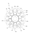
- An example of this modification is shown in FIG. In FIG. 8, illustration of the frame, the shaft, and the like is omitted.
- the rotating electrical machine 1A of the present modification includes a stator 2A and a variable field structure rotor 3A.
- the stator 2A includes a stator core 21A having a plurality (12 in this example) of teeth 23A and a plurality (12 in this example) of stator windings 25A wound around the plurality of teeth 23A.
- Each of the plurality of teeth 23A is fixed to the cylindrical stator core portion 22A by a bolt 24A.
- the plurality of teeth 23A have a plurality (12 in this example) of slots 26A that are open on the inner peripheral side between the teeth 23A, and the stator winding 25A wound around the teeth 23A is accommodated in the slot 26A.
- the axial dimension Lr of the rotor core 31A is shorter than the axial dimension Ls of the stator core 21A by a predetermined length, and the axial dimension Lm of the permanent magnet 32A is The axial length Lr of the rotor core 31A is set shorter than the predetermined length.
- the teeth 23A of the stator core 21A have a circumferential width Wt of 70% or more of the slot pitch Wp (Wt ⁇ 0.7Wp) at the end on the inner peripheral side, or between the teeth at the end on the inner peripheral side. It is set to at least twice the distance Ws (Wt ⁇ 2 Ws). With such a dimensional relationship, the circumferential width of the teeth 23A can be increased, and the inter-tooth distance Ws can be reduced.
- the rotor 3A includes a cylindrical rotor core 31A disposed with a magnetic gap inside the stator 2A, a cylindrical member 55 disposed inside the rotor core 31A, and the interior of the rotor core 31A.
- the rotor core 31A is subjected to quenching at least in part. That is, similar to the rotor core 31 in the above embodiment, the hardened steel plate 37A is laminated after being quenched.
- the plurality of first permanent magnets 32A are arranged in such a manner that N poles or S poles having the same polarity are opposed to each other in the circumferential direction, and the opposite magnetic poles having the same polarity are alternately changed in the circumferential direction. Has been placed. As a result, a plurality (ten in this example) of magnetic pole portions 34A of N poles and S poles having different polarities are formed in the circumferential direction of the rotor core 31A.
- the cylindrical member 55 is fixed to the shaft 10 (not shown).
- the rotor core 31A is provided so as to be rotatable relative to the cylindrical member 55 by a rotation mechanism (not shown).
- the rotor 3A rotates the rotor core 31A relative to the cylindrical member 55, and changes the position of the first permanent magnet 32A of the rotor core 31A with respect to the second permanent magnet 56 of the cylindrical member 55. It is possible to vary the field magnetic flux generated.
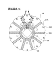
- FIG. 9 shows a state in which the field magnetic flux is small.
- the rotor core 31A and the cylindrical member 55 are at an angular position where the magnetic pole portion 34A and the second permanent magnet 56 having different polarities face each other in the radial direction.
- the magnetic flux of the magnetic pole portion 34A leaks to the second permanent magnet 56 side, so the field magnetic flux becomes small.
- FIG. 10 shows a state in which the field magnetic flux is medium.
- the rotor core 31A and the cylindrical member 55 are at an angular position where the magnetic pole portion 34A and the intermediate position between the two second permanent magnets 56 and 56 face each other in the radial direction.
- the field magnetic flux is medium.
- FIG. 11 shows a state where the load torque is large.
- the rotor core 31A and the cylindrical member 55 are at angular positions where the polarities of the magnetic pole portion 34A and the second permanent magnet 56 coincide.
- the magnetic flux of the magnetic pole portion 34A leaking to the second permanent magnet 56 side is almost eliminated, and the magnetic flux of the magnetic pole portion 34A is strengthened by the second permanent magnet 56, so that the field magnetic flux becomes maximum.
Landscapes
- Engineering & Computer Science (AREA)
- Power Engineering (AREA)
- Manufacturing & Machinery (AREA)
- Iron Core Of Rotating Electric Machines (AREA)
- Permanent Field Magnets Of Synchronous Machinery (AREA)
Abstract
[Problème] L'invention a pour objet d'accroître le rendement d'une machine électrique tournante. [Solution] Une machine électrique tournante 1 comprend: un noyau 21 de stator; un noyau 31 de rotor muni d'une pluralité de tôles feuilletées 37 en acier et présentant une dimension Lr dans la direction axiale plus courte que celle du noyau 21 de stator; et un aimant permanent 32 noyé dans le noyau 31 de rotor et présentant une dimension Lm dans la direction axiale plus courte que celle du noyau 31 de rotor. Le noyau 31 de rotor est structuré par feuilletage des tôles 37 en acier qui présentent une trempabilité et ont subi un traitement thermique. Le noyau 21 de stator comprend une pluralité de dents 23b autour desquelles des enroulements 25 stator sont enroulés et une partie 23a de raccordement servant à raccorder les extrémités des dents 23b du côté circonférentiel intérieur en une forme cylindrique.
Priority Applications (1)
| Application Number | Priority Date | Filing Date | Title |
|---|---|---|---|
| PCT/JP2014/073360 WO2016035191A1 (fr) | 2014-09-04 | 2014-09-04 | Machine électrique tournante et procédé de fabrication d'un noyau de rotor |
Applications Claiming Priority (1)
| Application Number | Priority Date | Filing Date | Title |
|---|---|---|---|
| PCT/JP2014/073360 WO2016035191A1 (fr) | 2014-09-04 | 2014-09-04 | Machine électrique tournante et procédé de fabrication d'un noyau de rotor |
Publications (1)
| Publication Number | Publication Date |
|---|---|
| WO2016035191A1 true WO2016035191A1 (fr) | 2016-03-10 |
Family
ID=55439290
Family Applications (1)
| Application Number | Title | Priority Date | Filing Date |
|---|---|---|---|
| PCT/JP2014/073360 Ceased WO2016035191A1 (fr) | 2014-09-04 | 2014-09-04 | Machine électrique tournante et procédé de fabrication d'un noyau de rotor |
Country Status (1)
| Country | Link |
|---|---|
| WO (1) | WO2016035191A1 (fr) |
Cited By (4)
| Publication number | Priority date | Publication date | Assignee | Title |
|---|---|---|---|---|
| WO2018008417A1 (fr) * | 2016-07-06 | 2018-01-11 | パナソニック株式会社 | Stratifié de plaque magnétique, procédé de fabrication correspondant et moteur utilisant ledit stratifié de plaque magnétique |
| JP2020150691A (ja) * | 2019-03-14 | 2020-09-17 | 三菱電機株式会社 | ロータ、および回転電機 |
| JP2022079056A (ja) * | 2020-11-16 | 2022-05-26 | 多摩川精機株式会社 | モータ軸構造 |
| US20230275478A1 (en) * | 2020-08-11 | 2023-08-31 | Scania Cv Ab | Rotor and Electrical Machine |
Citations (7)
| Publication number | Priority date | Publication date | Assignee | Title |
|---|---|---|---|---|
| JPH11234931A (ja) * | 1998-02-19 | 1999-08-27 | Hitachi Ltd | 永久磁石式回転電機 |
| JP2004260976A (ja) * | 2003-02-27 | 2004-09-16 | Fujitsu General Ltd | 誘導電動機 |
| JP2008036671A (ja) * | 2006-08-04 | 2008-02-21 | Nippon Steel Corp | 鋼板剪断面の鋼板間抵抗が高い電磁鋼の積層鋼板およびそのカシメ方法 |
| JP2009153230A (ja) * | 2007-12-18 | 2009-07-09 | Yaskawa Electric Corp | ロータコアの製造方法、該製造方法により製造されたロータコア、およびそのロータ、並びに該ロータを有する埋込磁石型回転電機、さらに該回転電機を用いた車両、昇降機、および加工機。 |
| JP2010011640A (ja) * | 2008-06-27 | 2010-01-14 | Hitachi Ltd | 永久磁石式回転電機 |
| JP2011182488A (ja) * | 2010-02-26 | 2011-09-15 | Toyota Boshoku Corp | モータコア及びその組付け方法 |
| JP2014093914A (ja) * | 2012-11-06 | 2014-05-19 | Mitsuba Corp | ブラシレスモータ |
-
2014
- 2014-09-04 WO PCT/JP2014/073360 patent/WO2016035191A1/fr not_active Ceased
Patent Citations (7)
| Publication number | Priority date | Publication date | Assignee | Title |
|---|---|---|---|---|
| JPH11234931A (ja) * | 1998-02-19 | 1999-08-27 | Hitachi Ltd | 永久磁石式回転電機 |
| JP2004260976A (ja) * | 2003-02-27 | 2004-09-16 | Fujitsu General Ltd | 誘導電動機 |
| JP2008036671A (ja) * | 2006-08-04 | 2008-02-21 | Nippon Steel Corp | 鋼板剪断面の鋼板間抵抗が高い電磁鋼の積層鋼板およびそのカシメ方法 |
| JP2009153230A (ja) * | 2007-12-18 | 2009-07-09 | Yaskawa Electric Corp | ロータコアの製造方法、該製造方法により製造されたロータコア、およびそのロータ、並びに該ロータを有する埋込磁石型回転電機、さらに該回転電機を用いた車両、昇降機、および加工機。 |
| JP2010011640A (ja) * | 2008-06-27 | 2010-01-14 | Hitachi Ltd | 永久磁石式回転電機 |
| JP2011182488A (ja) * | 2010-02-26 | 2011-09-15 | Toyota Boshoku Corp | モータコア及びその組付け方法 |
| JP2014093914A (ja) * | 2012-11-06 | 2014-05-19 | Mitsuba Corp | ブラシレスモータ |
Cited By (8)
| Publication number | Priority date | Publication date | Assignee | Title |
|---|---|---|---|---|
| WO2018008417A1 (fr) * | 2016-07-06 | 2018-01-11 | パナソニック株式会社 | Stratifié de plaque magnétique, procédé de fabrication correspondant et moteur utilisant ledit stratifié de plaque magnétique |
| JPWO2018008417A1 (ja) * | 2016-07-06 | 2018-12-20 | パナソニック株式会社 | 磁性板の積層体及びその製造方法、その積層体を用いたモータ |
| JP2020039249A (ja) * | 2016-07-06 | 2020-03-12 | パナソニック株式会社 | 磁性板の積層体、その製造方法及びその積層体を用いたモータ |
| US10797541B2 (en) | 2016-07-06 | 2020-10-06 | Panasonic Corporation | Magnetic plate laminate, manufacturing method therefor, and motor using this laminate |
| JP2020150691A (ja) * | 2019-03-14 | 2020-09-17 | 三菱電機株式会社 | ロータ、および回転電機 |
| US20230275478A1 (en) * | 2020-08-11 | 2023-08-31 | Scania Cv Ab | Rotor and Electrical Machine |
| JP2022079056A (ja) * | 2020-11-16 | 2022-05-26 | 多摩川精機株式会社 | モータ軸構造 |
| JP7780168B2 (ja) | 2020-11-16 | 2025-12-04 | 多摩川精機株式会社 | モータ軸構造 |
Similar Documents
| Publication | Publication Date | Title |
|---|---|---|
| CN101529698B (zh) | 永磁式马达及封闭式压缩机及风机马达 | |
| JP5255996B2 (ja) | 電機子鉄心,該電機子鉄心を用いたモータ、及びその製造方法 | |
| KR20180048819A (ko) | 전동기 및 공기 조화기 | |
| JP5594492B2 (ja) | 回転電機 | |
| WO2011122111A1 (fr) | Machine électrique dynamo | |
| JP2008193778A (ja) | 固定子及び密閉型圧縮機及び回転機 | |
| JP5920637B2 (ja) | 回転電機の回転子 | |
| JP5256724B2 (ja) | ロータコアの製造方法、該製造方法により製造されたロータコア、およびそのロータ、並びに該ロータを有する埋込磁石型回転電機、さらに該回転電機を用いた車両、昇降機、および加工機。 | |
| JP2010226785A (ja) | 板状部材の製造方法と、板状部材、および板状部材を用いたロータとこのロータを有する埋込磁石型回転電機 | |
| WO2017061305A1 (fr) | Stator et machine électrique rotative | |
| JP2013102597A (ja) | 電動機用ロータおよびブラシレスモータ | |
| JP2016072995A (ja) | 埋め込み磁石型ロータおよびそれを備えた電動機 | |
| CN105191069A (zh) | 永磁体嵌入式旋转电机 | |
| JP5634338B2 (ja) | 磁石モータ及び磁石モータを備えたドラム式洗濯機 | |
| JP2011019398A (ja) | 固定子及び密閉型圧縮機及び回転機 | |
| JP2017112705A (ja) | 永久磁石式回転電機及びその製造方法 | |
| JPWO2017158642A1 (ja) | 永久磁石式回転電機及びその製造方法 | |
| JP4080273B2 (ja) | 永久磁石埋め込み型電動機 | |
| JP6137854B2 (ja) | 永久磁石式電動機 | |
| JP3658507B2 (ja) | 永久磁石回転電機およびそれを用いた電気車両 | |
| JP3807214B2 (ja) | 永久磁石回転電機およびそれを用いた電気車両 | |
| JP2011041446A (ja) | ロータコアの製造方法、該製造方法により製造されたロータコア、該ロータコアを有する埋込磁石型回転電機 | |
| JP6357870B2 (ja) | 永久磁石式電動機 | |
| JP2010207021A (ja) | 回転子用エンドプレートおよびこれを用いた回転電機 | |
| JP6311274B2 (ja) | 回転電機用ロータの製造方法 |
Legal Events
| Date | Code | Title | Description |
|---|---|---|---|
| 121 | Ep: the epo has been informed by wipo that ep was designated in this application |
Ref document number: 14901381 Country of ref document: EP Kind code of ref document: A1 |
|
| NENP | Non-entry into the national phase |
Ref country code: DE |
|
| NENP | Non-entry into the national phase |
Ref country code: JP |
|
| 122 | Ep: pct application non-entry in european phase |
Ref document number: 14901381 Country of ref document: EP Kind code of ref document: A1 |