WO2016035316A1 - 厚肉油井用鋼管及びその製造方法 - Google Patents
厚肉油井用鋼管及びその製造方法 Download PDFInfo
- Publication number
- WO2016035316A1 WO2016035316A1 PCT/JP2015/004403 JP2015004403W WO2016035316A1 WO 2016035316 A1 WO2016035316 A1 WO 2016035316A1 JP 2015004403 W JP2015004403 W JP 2015004403W WO 2016035316 A1 WO2016035316 A1 WO 2016035316A1
- Authority
- WO
- WIPO (PCT)
- Prior art keywords
- less
- quenching
- content
- steel
- steel pipe
- Prior art date
- Legal status (The legal status is an assumption and is not a legal conclusion. Google has not performed a legal analysis and makes no representation as to the accuracy of the status listed.)
- Ceased
Links
Images


Classifications
-
- C—CHEMISTRY; METALLURGY
- C22—METALLURGY; FERROUS OR NON-FERROUS ALLOYS; TREATMENT OF ALLOYS OR NON-FERROUS METALS
- C22C—ALLOYS
- C22C38/00—Ferrous alloys, e.g. steel alloys
- C22C38/18—Ferrous alloys, e.g. steel alloys containing chromium
- C22C38/40—Ferrous alloys, e.g. steel alloys containing chromium with nickel
- C22C38/44—Ferrous alloys, e.g. steel alloys containing chromium with nickel with molybdenum or tungsten
-
- C—CHEMISTRY; METALLURGY
- C22—METALLURGY; FERROUS OR NON-FERROUS ALLOYS; TREATMENT OF ALLOYS OR NON-FERROUS METALS
- C22C—ALLOYS
- C22C38/00—Ferrous alloys, e.g. steel alloys
- C22C38/18—Ferrous alloys, e.g. steel alloys containing chromium
- C22C38/32—Ferrous alloys, e.g. steel alloys containing chromium with boron
-
- C—CHEMISTRY; METALLURGY
- C21—METALLURGY OF IRON
- C21D—MODIFYING THE PHYSICAL STRUCTURE OF FERROUS METALS; GENERAL DEVICES FOR HEAT TREATMENT OF FERROUS OR NON-FERROUS METALS OR ALLOYS; MAKING METAL MALLEABLE, e.g. BY DECARBURISATION OR TEMPERING
- C21D6/00—Heat treatment of ferrous alloys
- C21D6/004—Heat treatment of ferrous alloys containing Cr and Ni
-
- C—CHEMISTRY; METALLURGY
- C21—METALLURGY OF IRON
- C21D—MODIFYING THE PHYSICAL STRUCTURE OF FERROUS METALS; GENERAL DEVICES FOR HEAT TREATMENT OF FERROUS OR NON-FERROUS METALS OR ALLOYS; MAKING METAL MALLEABLE, e.g. BY DECARBURISATION OR TEMPERING
- C21D9/00—Heat treatment, e.g. annealing, hardening, quenching or tempering, adapted for particular articles; Furnaces therefor
- C21D9/08—Heat treatment, e.g. annealing, hardening, quenching or tempering, adapted for particular articles; Furnaces therefor for tubular bodies or pipes
- C21D9/085—Cooling or quenching
-
- C—CHEMISTRY; METALLURGY
- C22—METALLURGY; FERROUS OR NON-FERROUS ALLOYS; TREATMENT OF ALLOYS OR NON-FERROUS METALS
- C22C—ALLOYS
- C22C38/00—Ferrous alloys, e.g. steel alloys
-
- C—CHEMISTRY; METALLURGY
- C22—METALLURGY; FERROUS OR NON-FERROUS ALLOYS; TREATMENT OF ALLOYS OR NON-FERROUS METALS
- C22C—ALLOYS
- C22C38/00—Ferrous alloys, e.g. steel alloys
- C22C38/001—Ferrous alloys, e.g. steel alloys containing N
-
- C—CHEMISTRY; METALLURGY
- C22—METALLURGY; FERROUS OR NON-FERROUS ALLOYS; TREATMENT OF ALLOYS OR NON-FERROUS METALS
- C22C—ALLOYS
- C22C38/00—Ferrous alloys, e.g. steel alloys
- C22C38/002—Ferrous alloys, e.g. steel alloys containing In, Mg, or other elements not provided for in one single group C22C38/001 - C22C38/60
-
- C—CHEMISTRY; METALLURGY
- C22—METALLURGY; FERROUS OR NON-FERROUS ALLOYS; TREATMENT OF ALLOYS OR NON-FERROUS METALS
- C22C—ALLOYS
- C22C38/00—Ferrous alloys, e.g. steel alloys
- C22C38/005—Ferrous alloys, e.g. steel alloys containing rare earths, i.e. Sc, Y, Lanthanides
-
- C—CHEMISTRY; METALLURGY
- C22—METALLURGY; FERROUS OR NON-FERROUS ALLOYS; TREATMENT OF ALLOYS OR NON-FERROUS METALS
- C22C—ALLOYS
- C22C38/00—Ferrous alloys, e.g. steel alloys
- C22C38/02—Ferrous alloys, e.g. steel alloys containing silicon
-
- C—CHEMISTRY; METALLURGY
- C22—METALLURGY; FERROUS OR NON-FERROUS ALLOYS; TREATMENT OF ALLOYS OR NON-FERROUS METALS
- C22C—ALLOYS
- C22C38/00—Ferrous alloys, e.g. steel alloys
- C22C38/04—Ferrous alloys, e.g. steel alloys containing manganese
-
- C—CHEMISTRY; METALLURGY
- C22—METALLURGY; FERROUS OR NON-FERROUS ALLOYS; TREATMENT OF ALLOYS OR NON-FERROUS METALS
- C22C—ALLOYS
- C22C38/00—Ferrous alloys, e.g. steel alloys
- C22C38/06—Ferrous alloys, e.g. steel alloys containing aluminium
-
- C—CHEMISTRY; METALLURGY
- C22—METALLURGY; FERROUS OR NON-FERROUS ALLOYS; TREATMENT OF ALLOYS OR NON-FERROUS METALS
- C22C—ALLOYS
- C22C38/00—Ferrous alloys, e.g. steel alloys
- C22C38/18—Ferrous alloys, e.g. steel alloys containing chromium
- C22C38/40—Ferrous alloys, e.g. steel alloys containing chromium with nickel
- C22C38/42—Ferrous alloys, e.g. steel alloys containing chromium with nickel with copper
-
- C—CHEMISTRY; METALLURGY
- C22—METALLURGY; FERROUS OR NON-FERROUS ALLOYS; TREATMENT OF ALLOYS OR NON-FERROUS METALS
- C22C—ALLOYS
- C22C38/00—Ferrous alloys, e.g. steel alloys
- C22C38/18—Ferrous alloys, e.g. steel alloys containing chromium
- C22C38/40—Ferrous alloys, e.g. steel alloys containing chromium with nickel
- C22C38/46—Ferrous alloys, e.g. steel alloys containing chromium with nickel with vanadium
-
- C—CHEMISTRY; METALLURGY
- C22—METALLURGY; FERROUS OR NON-FERROUS ALLOYS; TREATMENT OF ALLOYS OR NON-FERROUS METALS
- C22C—ALLOYS
- C22C38/00—Ferrous alloys, e.g. steel alloys
- C22C38/18—Ferrous alloys, e.g. steel alloys containing chromium
- C22C38/40—Ferrous alloys, e.g. steel alloys containing chromium with nickel
- C22C38/48—Ferrous alloys, e.g. steel alloys containing chromium with nickel with niobium or tantalum
-
- C—CHEMISTRY; METALLURGY
- C22—METALLURGY; FERROUS OR NON-FERROUS ALLOYS; TREATMENT OF ALLOYS OR NON-FERROUS METALS
- C22C—ALLOYS
- C22C38/00—Ferrous alloys, e.g. steel alloys
- C22C38/18—Ferrous alloys, e.g. steel alloys containing chromium
- C22C38/40—Ferrous alloys, e.g. steel alloys containing chromium with nickel
- C22C38/50—Ferrous alloys, e.g. steel alloys containing chromium with nickel with titanium or zirconium
-
- C—CHEMISTRY; METALLURGY
- C22—METALLURGY; FERROUS OR NON-FERROUS ALLOYS; TREATMENT OF ALLOYS OR NON-FERROUS METALS
- C22C—ALLOYS
- C22C38/00—Ferrous alloys, e.g. steel alloys
- C22C38/18—Ferrous alloys, e.g. steel alloys containing chromium
- C22C38/40—Ferrous alloys, e.g. steel alloys containing chromium with nickel
- C22C38/54—Ferrous alloys, e.g. steel alloys containing chromium with nickel with boron
Definitions
- the present invention relates to an oil well steel pipe and a method for producing the same, and more particularly to a thick oil well steel pipe having a thickness of 40 mm or more and a method for producing the same.
- oil wells and gas wells are simply referred to as “oil wells”.
- oil wells and gas wells are simply referred to as “oil wells”.
- steel pipes for oil wells of 80 ksi class yield strength is 80 to 95 ksi, that is, 551 to 654 MPa
- 95 ksi class yield strength is 95 to 110 ksi, that is, 654 to 758 MPa
- oil well steel pipes of 110 ksi class yield strength is 110 to 125 ksi, that is, 758 to 862 MPa
- SSC resistance sulfide Stress Cracking resistance
- Patent Document 1 Japanese Patent Application Laid-Open No. Sho 62-253720
- Patent Document 2 Japanese Patent Laid-Open No. 59-232220
- the oil well steel pipe disclosed in Japanese Patent Application Laid-Open No. 2006-265657 is C: 0.30 to 0.60%, Cr + Mo: 1.5 to 3.0% (Mo is 0.5% or more) ) And the like are manufactured by performing tempering after oil-cooled quenching or austempering.
- Patent Document 3 is C: 0.30 to 0.60%, Cr + Mo: 1.5 to 3.0% (Mo is 0.5% or more) ) And the like are manufactured by performing tempering after oil-cooled quenching or austempering.
- the above-described manufacturing method can suppress quench cracking that is likely to occur during quenching of high C low alloy steel, and obtain oil well steel or oil well steel pipe having excellent SSC resistance.
- Patent Document 4 The oil well steel disclosed in Japanese Patent No. 5333700 (Patent Document 4) contains C: 0.56 to 1.00%, Mo: 0.40 to 1.00%, and was obtained by X-ray diffraction. (211) The half width of the crystal plane is 0.50 deg or less, and the yield strength is 862 MPa or more.
- SSC resistance is improved by spheroidizing the grain boundary carbides, and that spheroidization of carbides during high-temperature tempering is further promoted by increasing the C content.
- Patent Document 4 in order to suppress quench cracking due to the high C alloy, the cooling rate during quenching is limited, or the cooling is temporarily stopped during quenching, and the isothermal treatment is performed at a temperature exceeding 100 ° C to 300 ° C. There are proposals to implement it.
- Patent Document 5 contains C: more than 0.35% to 1.00%, Mo: more than 1.0% to 10%, etc.
- the product of the content and the Mo content is 0.6 or more.
- the oil well tubular steel further has an equivalent circle diameter of 1 nm or more, and the number of M 2 C carbides having a hexagonal structure is 5 or more per 1 ⁇ m 2. (211) Half width and C concentration of crystal plane Satisfies a specific relationship.
- the oil well tubular steel further has a yield strength of 758 MPa or more.
- Patent Document 5 the same quenching method as Patent Document 4 is adopted.
- Patent Documents 3 to 5 even when the techniques of Patent Documents 3 to 5 are used, excellent SSC resistance and high strength can be obtained with thick oil well steel pipes, more specifically with oil well steel pipes having a wall thickness of 40 mm or more. Is difficult. In particular, a thick oil well steel pipe has high strength and it is difficult to reduce variations in strength in the thickness direction.
- An object of the present invention is to provide a thick oil well steel pipe having a wall thickness of 40 mm or more, excellent SSC resistance, high strength (827 MPa or more), and less variation in strength in the thickness direction. It is.
- the thick oil well steel pipe according to the present invention has a wall thickness of 40 mm or more.
- Thick-walled steel well pipes are in mass%, C: 0.40 to 0.65%, Si: 0.05 to 0.50%, Mn: 0.10 to 1.0%, P: 0.020%
- S 0.0020% or less
- Al 0.005 to 0.10%
- Cr more than 0.40 to 2.0%
- Mo more than 1.15 to 5.0%
- Cu 0.50% or less
- V 0-0.25%
- Nb 0-0.10%
- Ti 0-0.05%
- Zr 0-0.
- the balance has a chemical composition composed of Fe and impurities. Further, the number of carbides having an equivalent circle diameter of 100 nm or more and containing 20% by mass or more of Mo is 2 pieces / 100 ⁇ m 2 or less. Further, the thick oil well steel pipe has a yield strength of 827 MPa or more, and a difference between the maximum value and the minimum value of the yield strength in the thickness direction is within 45 MPa.
- a method for producing a steel pipe for a thick oil well includes a step of producing a steel pipe having the above-described chemical composition, and one or a plurality of quenching treatments for the steel pipe, and quenching by at least one quenching treatment A step of setting the temperature to 925 to 1100 ° C., and a step of tempering after the quenching treatment.
- the steel pipe for thick oil well according to the present invention has a wall thickness of 40 mm or more, has excellent SSC resistance and high strength (827 MPa or more), and has little strength variation in the thickness direction.
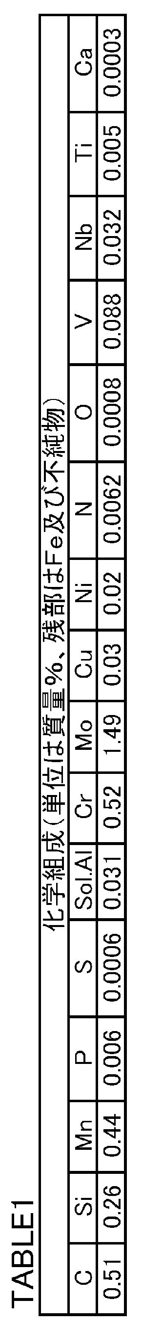
- FIG. 1 is a graph showing Rockwell hardness (HRC) in the thickness direction of a thick oil well steel pipe having the chemical composition shown in Table 1.
- FIG. 2 is a diagram showing the relationship between the tempering temperature for the thick oil well steel pipe having the chemical composition shown in Table 1 and the yield strength at the outer surface portion, the thickness center portion, and the inner surface portion of the thick oil well steel pipe.
- FIG. 3 is a diagram showing Jominy test results for steel materials having the chemical compositions shown in Table 1.
- FIG. 4 is a transmission electron microscope (TEM) image of the steel material quenched at a quenching temperature of 850 ° C. in FIG.
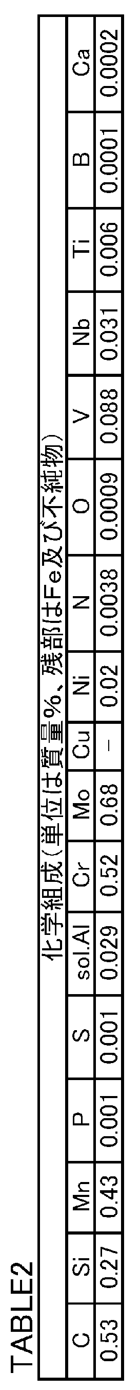
- FIG. 5 is a diagram showing Jominy test results for steel materials having the chemical compositions shown in Table 2.
- FIG. 6 is a diagram showing Jominy test results when the number of quenching treatments is changed using steel materials having the chemical composition shown in Table 1.
- the present inventors have completed the present invention based on the following findings.
- the Mn content should be 1.0% or less and the Cr content should be 2.0% or less.
- the C content should be 0.40% or more and the Mo content should be higher than 1.15%.
- the hardenability can be improved while maintaining the SSC resistance. The higher the hardenability, the higher the strength of the steel.
- the carbide in the steel tends to be spheroidized. Therefore, the SSC resistance is increased. Furthermore, the strength of steel can be increased by precipitation strengthening of carbides.
- the quenching temperature is set to 925 to 1100 ° C. in at least one quenching process performed one or more times.
- Mo carbides are sufficiently dissolved.
- the yield strength can be 827 MPa or more, and the variation in the yield strength in the thickness direction (maximum value-minimum value) can be suppressed to 45 MPa or less.
- a 40 mm thick seamless steel pipe having the chemical composition shown in Table 1 was produced.
- the manufactured steel pipe was heated at a quenching temperature of 900 ° C. Then, mist cooling was implemented with respect to the outer surface of the steel pipe, and the hardening process was performed.
- the Rockwell hardness (HRC) in the thickness direction was measured. Specifically, in the cross section, a Rockwell hardness (HRC) test in accordance with JIS Z2245 (2011) was performed at intervals of 2 mm from the inner surface toward the outer surface.
- Equation (1) means the lower limit Rockwell hardness at which martensite is 90% or more.
- C means C (carbon) content (mass%) of steel.
- the Rockwell hardness greatly decreased from the outer surface toward the inner surface, and in the range from the thickness center to the inner surface, the Rockwell hardness was less than HRCmin of the formula (1).
- the steel pipe was tempered at various tempering temperatures. And, from the outer surface of the steel pipe after tempering, a diameter of 6 mm and a parallel part of 40 mm are respectively obtained from a depth position of 6 mm (referred to as the first position on the outer surface), a central position on the thickness, and a position of 6 mm from the inner surface (referred to as the first position on the inner surface)
- a round bar tensile test piece was prepared. Using the produced tensile test piece, a tensile test was performed at room temperature (25 ° C.) and in the atmosphere to obtain a yield strength (ksi).
- FIG. 2 is a diagram showing the relationship between the tempering temperature (° C.) and the yield strength YS.
- a triangle mark ( ⁇ ) in FIG. 2 indicates the yield strength YS (ksi) at the first position on the outer surface.
- a circle ( ⁇ ) indicates the yield strength YS (ksi) at the center of the thickness.
- a square mark ( ⁇ ) indicates the yield strength YS (ksi) at the first position on the inner surface.
- the difference between the maximum value and the minimum value of the yield strength at the outer surface first position, the wall thickness center position, and the inner surface first position was large. That is, the hardness (strength) variation generated during the quenching process was not eliminated by the tempering process.
- FIG. 3 is a diagram showing a Jominy test result.
- rhombuses ( ⁇ ) indicate the results when the quenching temperature is 950 ° C.
- the triangle ( ⁇ ) indicates the result when the quenching temperature is 920 ° C.
- Square ( ⁇ ) marks indicate the results when the quenching temperature is 900 ° C, and circles ( ⁇ ) indicate the results when the quenching temperature is 850 ° C.
- the influence of the quenching temperature on the quenching depth was large.
- the quenching temperature is 950 ° C.
- the Rockwell hardness exceeds 60 HRC even at a distance of 30 mm from the water-cooled end, and the quenching temperature is significantly superior as compared with the case where the quenching temperature is less than 925 ° C. Admitted.
- FIG. 4 shows a microstructure photograph image (TEM image) of a steel material quenched at 850 ° C.
- TEM image microstructure photograph image
- EDX energy dispersive X-ray spectroscopy
- FIG. 5 is a diagram showing the Jominy test results.
- diamonds ( ⁇ ) indicate results when the quenching temperature is 950 ° C.
- the triangle ( ⁇ ) mark indicates the result when the quenching temperature is 920 ° C.
- the square ( ⁇ ) mark indicates the result when the quenching temperature is 900 ° C.
- the influence of the quenching temperature on the quenching depth is a phenomenon peculiar to high Mo high C low alloy steel having a C content of 0.40% or more and a Mo content higher than 1.15%. I found out.
- the black triangles ( ⁇ ) in FIG. 6 indicate that the quenching process is performed twice, the quenching temperature in the first quenching process is 950 ° C., the soaking time is 30 minutes, and the quenching temperature in the second quenching process. Is a Jominy test result when the temperature is 900 ° C. and the soaking time is 30 minutes.
- the white triangles ( ⁇ ) in FIG. 6 are Jominy test results when only one quenching is performed, the quenching temperature is 950 ° C., and the soaking time is 30 minutes. Referring to FIG. 6, when the quenching process is performed twice, the quenchability is improved if the quenching temperature in at least one quenching process is 925 ° C. or higher.
- a quenching treatment (hereinafter referred to as high temperature quenching) is performed on a high Mo high C low alloy steel at a quenching temperature of 925 ° C. or more, undissolved Mo carbide is sufficiently dissolved. Hardenability is significantly increased. As a result, a yield strength of 827 MPa or more can be obtained, and variations in the yield strength in the thickness direction can be reduced. Furthermore, since Cr content and Mn content can be suppressed, SSC resistance can also be improved.
- the thick oil well steel pipe according to the present embodiment completed based on the above knowledge has a wall thickness of 40 mm or more.
- Thick-walled steel well pipes are in mass%, C: 0.40 to 0.65%, Si: 0.05 to 0.50%, Mn: 0.10 to 1.0%, P: 0.020%
- S 0.0020% or less
- Al 0.005 to 0.10%
- Cr more than 0.40 to 2.0%
- Mo more than 1.15 to 5.0%
- Nb 0-0.10%
- Ti 0-0.05%
- Zr 0-0.
- the balance has a chemical composition composed of Fe and impurities. Further, the number of carbides having an equivalent circle diameter of 100 nm or more and containing 20% by mass or more of Mo is 2 pieces / 100 ⁇ m 2 or less. Further, the thick oil well steel pipe has a yield strength of 827 MPa or more, and the difference between the maximum value and the minimum value of the yield strength in the thickness direction is within 45 MPa.
- the method for manufacturing a steel pipe for a thick oil well includes a step of manufacturing a steel pipe having the above-described chemical composition, and one or a plurality of quenching processes for the steel pipe, and at least one quenching process.
- the carbon (C) content of the steel pipe for a low alloy oil well according to the present embodiment is higher than that of a conventional steel pipe for a low alloy oil well.
- C increases hardenability and increases the strength of the steel. If the C content is high, the spheroidization of the carbide during tempering is further promoted, and the SSC resistance is enhanced. C further combines with Mo or V to form carbides and increases temper softening resistance. If the carbide is dispersed, the strength of the steel is further increased. If the C content is too low, these effects cannot be obtained. On the other hand, if the C content is too high, the toughness of the steel is lowered and fire cracks are likely to occur. Therefore, the C content is 0.40 to 0.65%.
- the minimum with preferable C content is 0.45%, More preferably, it is 0.48%, More preferably, it is 0.51%.
- the upper limit with preferable C content is 0.60%, More preferably, it is 0.57%.
- Si 0.05 to 0.50% Silicon (Si) deoxidizes steel. If the Si content is too low, this effect cannot be obtained. On the other hand, if the Si content is too high, the SSC resistance decreases. Therefore, the Si content is 0.05 to 0.50%.
- the minimum of preferable Si content is 0.10%, More preferably, it is 0.15%.
- the upper limit of the preferable Si content is 0.40%, and more preferably 0.35%.
- Mn 0.10 to 1.0%
- Manganese (Mn) deoxidizes steel. Mn further enhances hardenability. If the Mn content is too low, this effect cannot be obtained. On the other hand, if the Mn content is too high, Mn segregates at grain boundaries together with impurity elements such as phosphorus (P) and sulfur (S). In this case, the SSC resistance and toughness of the steel are reduced. Therefore, the Mn content is 0.10 to 1.0%.
- the minimum of preferable Mn content is 0.20%, More preferably, it is 0.30%.
- the upper limit of the preferable Mn content is 0.80%, more preferably 0.60%.
- Phosphorus (P) is an impurity. P segregates at the grain boundaries and lowers the SSC resistance of the steel. Therefore, the P content is 0.020% or less. P content is preferably 0.015% or less, more preferably 0.012% or less. The P content is preferably as low as possible.
- S 0.0020% or less Sulfur (S) is an impurity. S segregates at the grain boundaries and lowers the SSC resistance of the steel. Therefore, the S content is 0.0020% or less. A preferable S content is 0.0015% or less, and more preferably 0.0010% or less. The S content is preferably as low as possible.
- Al 0.005 to 0.10%
- Aluminum (Al) deoxidizes steel. If the Al content is too low, this effect cannot be obtained and the SSC resistance of the steel decreases. On the other hand, if the Al content is too high, an oxide is generated and the SSC resistance of the steel is lowered. Therefore, the Al content is 0.005 to 0.10%.
- the minimum with preferable Al content is 0.010%, More preferably, it is 0.015%.
- the upper limit with preferable Al content is 0.08%, More preferably, it is 0.05%.
- Al content means “acid-soluble Al”, that is, the content of “sol. Al”.
- Chromium (Cr) increases the hardenability of the steel and increases the strength of the steel. If the Cr content is too low, the above effect cannot be obtained. On the other hand, if the Cr content is too high, the toughness and SSC resistance of the steel will decrease. Therefore, the Cr content is more than 0.40 to 2.0%.
- the minimum with preferable Cr content is 0.48%, More preferably, it is 0.50%, More preferably, it is 0.51%.
- the upper limit with preferable Cr content is 1.25%, More preferably, it is 1.15%.
- Mo more than 1.15 to 5.0% Molybdenum (Mo) significantly enhances the hardenability when the quenching temperature is 925 ° C. or higher. Mo further generates fine carbides and increases the temper softening resistance of the steel. As a result, Mo contributes to the improvement of SSC resistance by high temperature tempering. If the Mo content is too low, this effect cannot be obtained. On the other hand, if the Mo content is too high, the above effect is saturated. Therefore, the Mo content is more than 1.15 to 5.0%. The minimum with preferable Mo content is 1.20%, More preferably, it is 1.25%. The upper limit with preferable Mo content is 4.2%, More preferably, it is 3.5%.
- Cu 0.50% or less Copper (Cu) is an impurity. Cu reduces SSC resistance. Therefore, the Cu content is 0.50% or less. A preferable Cu content is 0.10% or less, and more preferably 0.02% or less.
- Nickel (Ni) is an impurity. Ni decreases the SSC resistance. Therefore, the Ni content is 0.50% or less.
- a preferable Ni content is 0.10% or less, and more preferably 0.02% or less.
- N 0.007% or less Nitrogen (N) is an impurity. N forms a nitride and makes the SSC resistance of the steel unstable. Therefore, the N content is 0.007% or less. A preferable N content is 0.005% or less. The N content is preferably as low as possible.
- Oxygen (O) is an impurity. O produces a coarse oxide and reduces the SSC resistance of the steel. Therefore, the O content is 0.005% or less. A preferable O content is 0.002% or less. The O content is preferably as low as possible.
- the remainder of the chemical composition of the steel pipe for thick oil wells of this embodiment consists of Fe and impurities.
- Impurities here refer to ores and scraps used as raw materials for steel, or elements mixed from the environment of the manufacturing process.
- the chemical composition of the thick oil well steel pipe of the present embodiment further includes one or more selected from the group consisting of V, Nb, Ti, Zr, and W instead of part of Fe. Also good.
- V 0 to 0.25%
- Vanadium (V) is an optional element and may not be contained. When contained, V forms carbides and increases the temper softening resistance of the steel. As a result, V contributes to the improvement of SSC resistance by high temperature tempering. However, if the V content is too high, the toughness of the steel decreases. Therefore, the V content is 0 to 0.25%.
- the minimum with preferable V content is 0.07%.
- the upper limit with preferable V content is 0.20%, More preferably, it is 0.15%.
- Niobium (Nb) is an optional element and may not be contained. When contained, Nb combines with C and / or N to form a carbide, nitride or carbonitride. These precipitates (carbides, nitrides and carbonitrides) refine the steel substructure by the pinning effect and increase the SSC resistance of the steel. However, if the Nb content is too high, an excessive amount of nitride is generated and the SSC resistance of the steel becomes unstable. Therefore, the Nb content is 0 to 0.10%. The minimum with preferable Nb content is 0.01%, More preferably, it is 0.013%. The upper limit with preferable Nb content is 0.07%, More preferably, it is 0.04%.
- Titanium (Ti) is an optional element and may not be contained. When contained, Ti forms a nitride and refines the crystal grains by the pinning effect. However, if the Ti content is too high, the Ti nitride becomes coarse and the SSC resistance of the steel decreases. Therefore, the Ti content is 0 to 0.05%.
- the minimum with preferable Ti content is 0.005%, More preferably, it is 0.008%.
- the upper limit with preferable Ti content is 0.02%, More preferably, it is 0.015%.
- Zr Zirconium
- Zr Zirconium
- Zr forms a nitride like Ti, and refines crystal grains by a pinning effect. However, if the Zr content is too high, the Zr nitride becomes coarse and the SSC resistance of the steel decreases. Therefore, the Zr content is 0 to 0.10%.
- the minimum with preferable Zr content is 0.005%, More preferably, it is 0.008%.
- the upper limit with preferable Zr content is 0.02%, More preferably, it is 0.015%.
- W 0-1.5% Tungsten (W) is an optional element and may not be contained. When contained, W forms carbides and increases the temper softening resistance of the steel. As a result, W contributes to the improvement of SSC resistance by high temperature tempering. W further increases the hardenability of steel, like Mo, and significantly increases the hardenability especially when the quenching temperature is 925 ° C. or higher. Therefore, W complements the effect of Mo. However, if the W content is too high, the effect is saturated. Furthermore, W is expensive. Therefore, the W content is 0 to 1.5%. The minimum with preferable W content is 0.05%, More preferably, it is 0.1%. The upper limit with preferable W content is 1.3%, More preferably, it is 1.0%.
- the thick-wall oil well steel pipe according to the present embodiment may further contain B instead of a part of Fe.
- B 0 to 0.005%
- Boron (B) is an optional element and may not be contained. When contained, B enhances hardenability. This effect appears if there is even a small amount of B in the steel that is not fixed to N. However, if the B content is too high, M 23 (CB) 6 is formed at the grain boundaries, and the SSC resistance of the steel decreases. Therefore, the B content is 0 to 0.005%. A preferable lower limit of the B content is 0.0005%. The upper limit with preferable B content is 0.003%, More preferably, it is 0.002%.
- the chemical composition of the thick oil well steel pipe according to the present embodiment may further include one or more selected from the group consisting of Ca, Mg and rare earth elements (REM) instead of a part of Fe. Good. All of these elements improve the SSC resistance of the steel by improving the shape of the sulfide. Ca: 0 to 0.003%, Mg: 0 to 0.003%, Rare earth element (REM): 0-0.003% Calcium (Ca), magnesium (Mg) and rare earth element (REM) are all optional elements and may not be contained. When contained, these elements combine with S in the steel to form sulfides. Thereby, the shape of sulfide is improved and the SSC resistance of steel is enhanced.
- REM further combines with P in the steel to suppress P segregation at the grain boundaries. For this reason, a decrease in the SSC resistance of the steel due to the segregation of P is suppressed.
- the Ca content is 0 to 0.003%
- the Mg content is 0 to 0.003%
- the REM is 0 to 0.003%.
- a preferable lower limit of the Ca content is 0.0005%.
- a preferable lower limit of the Mg content is 0.0005%.
- a preferable lower limit of the REM content is 0.0005%.
- REM is a generic name including 15 elements of lanthanoid, Y and Sc.
- the REM content means that one or more of these elements are contained.
- the REM content means the total content of these elements.
- the number of carbides having an equivalent circle diameter of 100 nm or more and containing 20% by mass or more of Mo is 2 pieces / 100 ⁇ m 2 or less.
- a carbide having an equivalent circle diameter of 100 nm or more is referred to as “coarse carbide”.
- a carbide containing 20% by mass or more of Mo is referred to as “Mo carbide”.
- the Mo content in the carbide refers to the Mo content when the total amount of metal elements is 100% by mass.
- Carbon (C) and nitrogen (N) are not included in the total amount of metal elements.
- Mo carbide having an equivalent circle diameter of 100 nm or more is referred to as “coarse Mo carbide”.
- the equivalent circle diameter means the diameter of a circle when the area of the carbide is converted into a circle having the same area.
- the thick oil well steel pipe of this embodiment by performing “high temperature quenching” at a quenching temperature of 925 ° C. or more, the number of undissolved coarse Mo carbides is reduced, and Mo and C are in the steel. To dissolve. Therefore, Mo and C improve hardenability and high strength is obtained. Furthermore, by increasing the solid solution amount of Mo and C, the strength variation in the thickness direction is also reduced.
- the yield strength is 827 MPa or more and the maximum yield strength in the thickness direction is obtained in a thick oil well steel pipe having a thickness of 40 mm or more.
- the difference between the value and the minimum value hereinafter referred to as the yield strength difference ⁇ YS) is 45 MPa or less.
- the number of coarse Mo carbides is measured by the following method.
- a sample for microstructural observation is taken from an arbitrary position in the center of the thick wall.
- a replica film is collected from the sample.
- the replica film can be collected, for example, under the following conditions. First, the observation surface of the sample is mirror-polished. Next, the polished observation surface is corroded by dipping in 3% nital at room temperature for 10 seconds. Thereafter, carbon deposition is performed to form a replica film on the observation surface.
- the sample on which the replica film is formed is immersed in 5% nital at room temperature for 10 seconds to corrode the interface between the replica film and the sample and peel off the replica film.
- TEM transmission electron microscope
- each field of view identify Mo carbides among carbides. Specifically, energy dispersive X-ray analysis (EDX) is performed on carbides in each field of view. Thereby, the content (including Mo) of each metal element in the carbide is measured.
- EDX energy dispersive X-ray analysis
- carbides when the total amount of metal elements is 100% by mass, a carbide containing 20% by mass or more of Mo is Mo carbide. Carbon (C) and nitrogen (N) are not included in the total amount of metal elements.
- Mo carbide having a measured equivalent circle diameter of 100 nm or more is identified as coarse Mo carbide.
- the average number of coarse Mo carbides in 10 fields of view is defined as the number N of coarse Mo carbides (pieces / 100 ⁇ m 2 ).
- the yield strength and yield strength difference ⁇ YS are measured by the following method.
- the diameter is 6 mm from the outer surface (outer surface first position), the center of the wall thickness, and the inner surface is 6 mm deep position (inner surface first position).
- a 40 mm round bar tensile test piece is prepared.
- the longitudinal direction of the test piece is parallel to the axial direction of the steel pipe.
- a tensile test is carried out at normal temperature (25 ° C.) and atmospheric pressure to obtain the yield strength YS at each position.
- the yield strength YS is 827 MPa or more at any position.
- the difference between the maximum value and the minimum value of the yield strength YS at the three positions is defined as the yield strength difference ⁇ YS (MPa).
- the yield strength difference ⁇ YS is within 45 MPa.
- the upper limit of yield strength is not particularly limited. However, in the case of the above chemical composition, the preferable upper limit of the yield strength is 930 MPa.
- the method for producing a seamless steel pipe includes a pipe making process, a quenching process, and a tempering process.
- the steel having the above chemical composition is melted and refined by a well-known method. Subsequently, the molten steel is made into a continuous cast material by a continuous casting method.
- the continuous cast material is, for example, a slab, bloom or billet.
- the molten steel may be ingot by an ingot-making method.
- a round billet may be formed by hot rolling, or a round billet may be formed by hot forging.
- the billet is hot-worked to produce a blank tube.
- the billet is heated in a heating furnace.
- the billet extracted from the heating furnace is hot-worked to produce a raw pipe (seamless steel pipe).
- the Mannesmann method is performed as hot working to manufacture a raw tube.
- the round billet is pierced and rolled by a piercing machine.
- the round billet that has been pierced and rolled is further hot-rolled by a mandrel mill, a reducer, a sizing mill, or the like into a blank tube.
- the blank tube may be manufactured from the billet by another hot working method.
- the raw pipe may be manufactured by forging.
- a steel pipe having a wall thickness of 40 mm or more is manufactured.
- the upper limit of the wall thickness is not particularly limited, but is preferably 65 mm or less from the viewpoint of controlling the cooling rate in the quenching process described later.
- the outer diameter of the steel pipe is not particularly limited.
- the outer diameter of the steel pipe is, for example, 250 to 500 mm.
- the steel pipe manufactured by hot working may be air-cooled (As-Rolled). Steel pipes manufactured by hot working can also be directly quenched after hot pipe making without cooling to room temperature, or after being reheated after hot pipe making and quenching. Good. However, when quenching directly after quenching or after supplementary heating (so-called in-line quenching), it is preferable to stop cooling during quenching or perform slow cooling for the purpose of suppressing quench cracking.
- the purpose of removing residual stress is to perform stress relief annealing after quenching and before the next heat treatment. It is preferable to carry out (SR processing).
- SR processing stress relief annealing after quenching and before the next heat treatment.
- Quenching process is performed on the blank after hot working. Quenching may be performed multiple times. However, at least once, the following high-temperature quenching process (quenching process at a quenching temperature of 925 to 1100 ° C. or lower) is performed.
- the quenching temperature is less than 925 ° C.
- undissolved Mo carbide is not sufficiently dissolved. Therefore, the number N of coarse Mo carbides is greater than 2/100 ⁇ m 2 .
- the yield strength of the thick oil well steel pipe is less than 827 MPa, or the yield strength difference ⁇ YS in the thickness direction exceeds 45 MPa.
- the quenching temperature exceeds 1100 ° C., the ⁇ grains become remarkably coarse, so that the SSC resistance decreases.
- the quenching temperature in the high-temperature quenching process is 925 to 1100 ° C.
- the Mo carbides are sufficiently dissolved, and the number N of coarse Mo carbides is 2/100 ⁇ m 2 or less. Therefore, the hardenability is significantly increased. Therefore, the yield strength of the thick oil well steel pipe after tempering is 827 MPa or more, and the yield strength difference ⁇ YS in the thickness direction is 45 MPa or less.
- a preferable lower limit of the quenching temperature in the high-temperature quenching treatment is 930 ° C, more preferably 940 ° C, and further preferably 950 ° C.
- the upper limit with a preferable quenching temperature is 1050 degreeC.
- the preferable soaking time in the high-temperature quenching process is 15 minutes or more. If the soaking time is 15 minutes or more, the Mo carbide is more easily dissolved. A preferable lower limit of the soaking time is 20 minutes. A preferable upper limit of the soaking time is 90 minutes. Even when the heating temperature is 1000 ° C. or more, if the soaking time is 90 minutes or less, the coarsening of the ⁇ grains is suppressed, and the SSC resistance is further improved. However, even if the soaking time exceeds 90 minutes, the SSC resistance can be obtained to some extent.
- the first quenching process is preferably a high-temperature quenching process.
- the Mo carbide is sufficiently dissolved by the first high-temperature quenching process. Therefore, even when the quenching temperature in the subsequent quenching process is a low temperature of less than 925 ° C., high hardenability can be obtained. As a result, the yield strength can be further increased.
- the cooling rate in the temperature range of 0 ° C. is preferably 0.5 to 5 ° C./second.
- the cooling rate is less than 0.5 ° C./second, the martensite ratio tends to be insufficient.
- the cooling rate exceeds 5 ° C./second burn cracking may occur.
- the cooling rate is 0.5 to 5 ° C./second, the martensite ratio in the steel is sufficiently increased, and as a result, the yield strength is increased.
- the cooling means is not particularly limited. For example, mist water cooling may be performed on the outer surface or inner and outer surfaces of the steel pipe, or cooling may be performed using a medium having a lower heat extraction capability than water such as oil or polymer.
- forced cooling at the above cooling rate is started before the temperature of the steel material at the latest cooling position becomes 600 ° C. or lower. In this case, it is easy to further increase the yield strength.
- the Rockwell hardness (HRC) is less than the HRCmin of the formula (1).
- the Rockwell hardness (HRC) is equal to or higher than HRCmin defined by the equation (1).
- a preferable lower limit of the cooling rate is 1.2 ° C./second.
- a preferable upper limit of the cooling rate is 4.0 ° C./second.
- the quenching process may be performed twice or more.
- at least one quenching process may be a high temperature quenching process.
- the SR treatment is performed as described above for the purpose of removing the residual stress caused by the quenching treatment. It is preferable to carry out.
- the treatment temperature should be 600 °C or less. SR treatment can prevent the occurrence of cracks after quenching. When the treatment temperature exceeds 600 ° C., the prior austenite grains after the final quenching may become coarse.
- Tempeering process A tempering process is implemented after implementing the above-mentioned hardening process.
- the tempering temperature is 650 ° C. to Ac 1 point. If the tempering temperature is less than 650 ° C., the spheroidization of the carbide becomes insufficient, and the SSC resistance decreases.
- a preferred lower limit of the tempering temperature is 660 ° C.
- a preferable upper limit of the tempering temperature is 700 ° C.
- a preferable soaking time for the tempering temperature is 15 to 120 minutes.
- Ingots were manufactured using molten steel of each mark. The ingot was hot-rolled to produce a steel plate that assumed a thick oil well steel pipe. The plate thickness (corresponding to the wall thickness) of the steel plate of each test number was as shown in Table 4.
- Heat treatment was performed under the heat treatment conditions shown in Table 4 on the steel plates of each test number after hot rolling.
- Table 4 in test number 1, quenching by mist cooling (mist Q) was performed once, quenching temperature was 950 ° C., soaking time was 30 minutes, and the steel sheet was cooled in a temperature range of 500 to 100 ° C. It indicates that the speed was 3 ° C./second (in Table 4, “Cold speed: 3 ° C./s”).
- Test No. 2 indicates that in the first quenching process, a quenching process by mist cooling was performed, the quenching temperature was 950 ° C., and the soaking time was 30 minutes. Thereafter, SR treatment (described as “SR” in Table 4) was performed, indicating that the heat treatment temperature was 580 ° C. and the soaking time was 10 minutes. Then, the quenching process by the 2nd mist cooling was implemented, the quenching temperature was 900 degreeC, the soaking time was 30 minutes, and the cooling rate was 2 degrees C / sec. In the quenching by mist cooling, mist water was sprayed on only one of the surfaces (two surfaces) of the steel plate. And the surface which sprayed mist water was assumed as the outer surface of a steel pipe, and the surface on the opposite side was assumed as the inner surface of a steel pipe.
- SR treatment described as “SR” in Table 4
- the cooling rate shown in Table 4 is an average cooling rate of 500 to 100 ° C. at the slowest cooling position among the steel plates of each test number.
- the tempering temperature was 680 to 720 ° C.
- the soaking time was 10 to 120 minutes.
- the Rockwell hardness was measured as follows with respect to the steel plate (as-quenched material) of each test number after the heat treatment (final quenching).
- 1.0 mm depth position from the outer surface (surface sprayed with mist water) (hereinafter referred to as “outer surface second position”), plate thickness center position corresponding to the thickness center (wall thickness center position), inner surface ( Rockwell hardness (HRC) test in conformity with JIS Z2245 (2011) at a depth position of 1.0 mm (hereinafter referred to as “inner surface second position”) from the surface opposite to the surface sprayed with mist water. Carried out.
- the Rockwell hardness (HRC) at three arbitrary positions is obtained at each outer surface second position, thickness center position, and inner surface second position, and the average is calculated for each position (outer surface second position, wall thickness position). It was defined as Rockwell hardness (HRC) at the thickness center position and the inner surface second position).
- Yield Strength (YS) and Tensile Strength (TS) Test From the outer surface (surface sprayed with mist water) of each test number after tempering, 6.0 mm depth position (outer surface first position), thickness center position, inner surface (opposite to the surface sprayed with mist water) A round bar tensile test piece having a diameter of 6 mm and a parallel portion length of 40 mm was produced at a depth position (first position on the inner surface) of 6.0 mm from the side surface. The axial direction of the tensile specimen was parallel to the rolling direction of the steel plate.
- a tensile test was carried out at room temperature (25 ° C.) and in the atmosphere to obtain a yield strength YS (MPa) and a tensile strength (TS) at each position. Furthermore, the yield strength difference ⁇ YS (MPa), which is the difference between the maximum value and the minimum value of the yield strength YS (MPa) at each position, was determined.
- test piece was subjected to a constant load type SSC resistance test in accordance with Method A of NACE-TM0177 (2005 version). Specifically, the test piece was immersed in a 24 ° C. NACE-A bath (H 2 S partial pressure was 1 bar), and the immersed test piece had a yield strength of 90 obtained in the above-described yield strength test. %. After elapse of 720 hours, it was observed whether or not the test piece was cracked. If no crack was observed, the SSC resistance was excellent (“NF” in Table 5), and if a crack was observed, it was determined that the SSC resistance was low (“F” in Table 5).
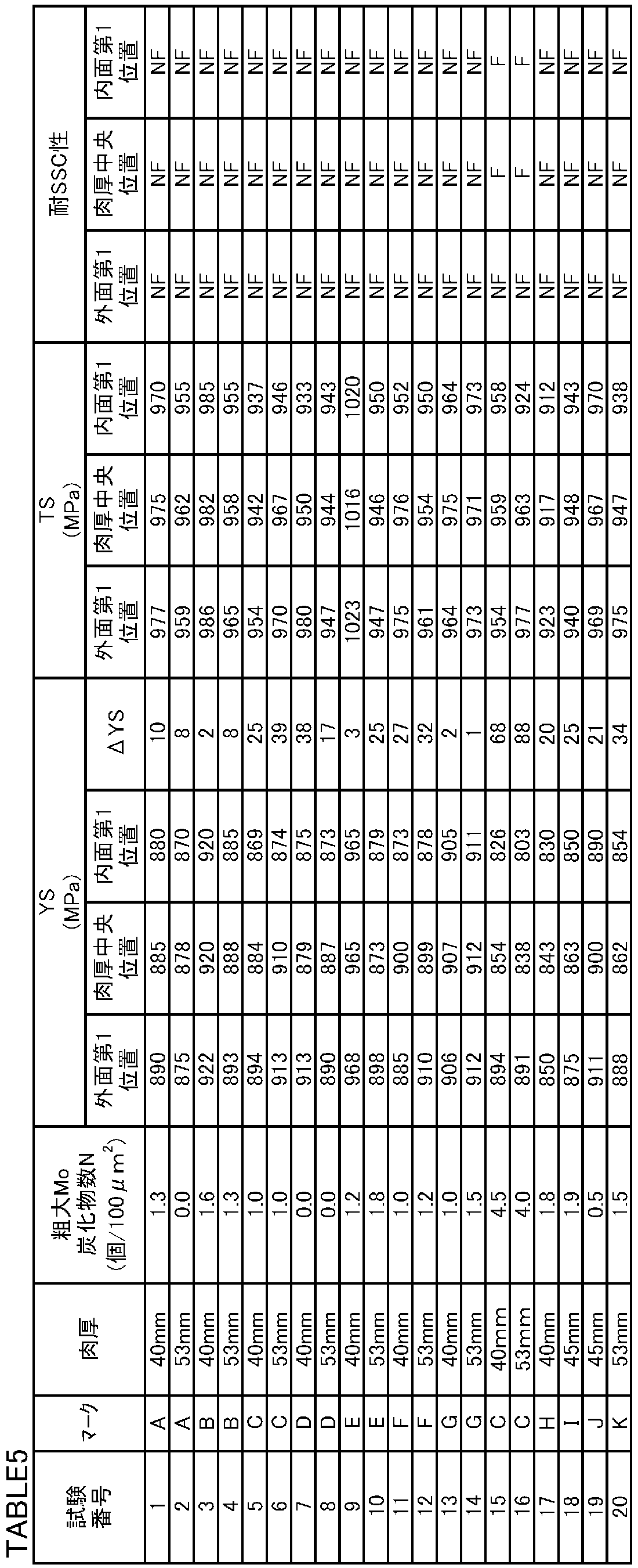
- Test results The test results are shown in Table 5.
- ⁇ YS in Table 5 indicates the yield strength difference of each test number.
- the chemical composition was appropriate, and the manufacturing conditions (quenching conditions) were also appropriate. Therefore, the number N of coarse Mo carbides in test numbers 1 to 14 and test numbers 17 to 20 was 2 pieces / 100 ⁇ m 2 or less. Therefore, the yield strength was 827 MPa or more at any position, and the yield strength difference ⁇ YS was within 45 MPa.
- the SSC resistance test no cracks were observed at any position (outer surface first position, thickness center position, and inner surface first position), indicating excellent SSC resistance.
- the Rockwell hardness before tempering (HRC, see Table 4) of Test Nos. 1 to 14 and Test Nos. 17 to 20 was higher than the HRCmin value calculated from the above equation (1).
- test numbers 15 and 16 were both appropriate.
- the quenching temperatures in the quenching treatment were all less than 925 ° C. Therefore, the number N of coarse Mo carbides in test numbers 15 and 16 was 2/100 ⁇ m 2 or more. Therefore, the yield strength at the first position on the inner surface was less than 827 MPa. Furthermore, the yield strength difference ⁇ YS exceeded 45 MPa. Furthermore, SSC was confirmed at the thickness center position and the inner surface first position.
Landscapes
- Chemical & Material Sciences (AREA)
- Engineering & Computer Science (AREA)
- Materials Engineering (AREA)
- Mechanical Engineering (AREA)
- Metallurgy (AREA)
- Organic Chemistry (AREA)
- Physics & Mathematics (AREA)
- Thermal Sciences (AREA)
- Crystallography & Structural Chemistry (AREA)
- Heat Treatment Of Articles (AREA)
- Heat Treatment Of Steel (AREA)
Abstract
Description
HRCmin=58×C+27 (1)
本実施形態による低合金油井用鋼管の化学組成は、次の元素を含有する。
本実施形態による低合金油井用鋼管の炭素(C)含有量は、従前の低合金油井用鋼管よりも高い。Cは、焼入れ性を高め、鋼の強度を高める。C含有量が高ければさらに、焼戻し時の炭化物の球状化が促進され、耐SSC性が高まる。Cはさらに、Mo又はVと結合して炭化物を形成し、焼戻し軟化抵抗を高める。炭化物が分散されればさらに、鋼の強度が高まる。C含有量が低すぎれば、これらの効果が得られない。一方、C含有量が高すぎれば、鋼の靭性が低下し、焼割れが発生しやすくなる。したがって、C含有量は0.40~0.65%である。C含有量の好ましい下限は0.45%であり、さらに好ましくは0.48%であり、さらに好ましくは0.51%である。C含有量の好ましい上限は0.60%であり、さらに好ましくは0.57%である。
シリコン(Si)は、鋼を脱酸する。Si含有量が低すぎれば、この効果が得られない。一方、Si含有量が高すぎれば、耐SSC性が低下する。したがって、Si含有量は、0.05~0.50%である。好ましいSi含有量の下限は、0.10%であり、さらに好ましくは、0.15%である。好ましいSi含有量の上限は、0.40%であり、さらに好ましくは、0.35%である。
マンガン(Mn)は、鋼を脱酸する。Mnはさらに、焼入れ性を高める。Mn含有量が低すぎれば、この効果が得られない。一方、Mn含有量が高すぎれば、Mnは、燐(P)及び硫黄(S)等の不純物元素とともに、粒界に偏析する。この場合、鋼の耐SSC性及び靭性が低下する。したがって、Mn含有量は、0.10~1.0%である。好ましいMn含有量の下限は、0.20%であり、さらに好ましくは0.30%である。好ましいMn含有量の上限は、0.80%であり、さらに好ましくは0.60%である。
燐(P)は不純物である。Pは、粒界に偏析して鋼の耐SSC性を低下する。したがって、P含有量は、0.020%以下である。好ましいP含有量は0.015%以下であり、さらに好ましくは0.012%以下である。P含有量はなるべく低い方が好ましい。
硫黄(S)は不純物である。Sは、粒界に偏析して鋼の耐SSC性を低下する。したがって、S含有量は0.0020%以下である。好ましいS含有量は0.0015%以下であり、さらに好ましくは0.0010%以下である。S含有量はなるべく低い方が好ましい。
アルミニウム(Al)は、鋼を脱酸する。Al含有量が低すぎれば、この効果が得られず、鋼の耐SSC性が低下する。一方、Al含有量が高すぎれば、酸化物が生成して鋼の耐SSC性が低下する。したがって、Al含有量は0.005~0.10%である。Al含有量の好ましい下限は0.010%であり、さらに好ましくは0.015%である。Al含有量の好ましい上限は0.08%であり、さらに好ましくは0.05%である。本明細書にいう「Al」含有量は「酸可溶Al」、つまり、「sol.Al」の含有量を意味する。
クロム(Cr)は、鋼の焼入れ性を高め、鋼の強度を高める。Cr含有量が低すぎれば、上記効果が得られない。一方、Cr含有量が高すぎれば、鋼の靭性及び耐SSC性が低下する。したがって、Cr含有量は0.40超~2.0%である。Cr含有量の好ましい下限は0.48%であり、さらに好ましくは0.50%であり、さらに好ましくは0.51%である。Cr含有量の好ましい上限は1.25%であり、さらに好ましくは1.15%である。
モリブデン(Mo)は、焼入れ温度が925℃以上である場合に、焼入れ性を顕著に高める。Moはさらに、微細な炭化物を生成し、鋼の焼戻し軟化抵抗を高める。その結果、Moは、高温焼戻しによる耐SSC性の向上に寄与する。Mo含有量が低すぎれば、この効果が得られない。一方、Mo含有量が高すぎれば、上記効果が飽和する。したがって、Mo含有量は1.15超~5.0%である。Mo含有量の好ましい下限は1.20%であり、さらに好ましくは1.25%である。Mo含有量の好ましい上限は4.2%であり、さらに好ましくは3.5%である。
銅(Cu)は不純物である。Cuは耐SSC性を低下させる。したがって、Cu含有量は0.50%以下である。好ましいCu含有量は0.10%以下であり、さらに好ましくは0.02%以下である。
ニッケル(Ni)は不純物である。Niは耐SSC性を低下する。したがって、Ni含有量は0.50%以下である。好ましいNi含有量は0.10%以下であり、さらに好ましくは0.02%以下である。
窒素(N)は不純物である。Nは窒化物を形成し、鋼の耐SSC性を不安定にする。したがって、N含有量は0.007%以下である。好ましいN含有量は0.005%以下である。N含有量はなるべく低い方が好ましい。
酸素(O)は不純物である。Oは粗大な酸化物を生成して鋼の耐SSC性を低下する。したがって、O含有量は0.005%以下である。好ましいO含有量は0.002%以下である。O含有量はなるべく低い方が好ましい。
バナジウム(V)は任意元素であり、含有されなくてもよい。含有される場合、Vは炭化物を形成して、鋼の焼戻し軟化抵抗を高める。その結果、Vは、高温焼戻しによる耐SSC性の向上に寄与する。しかしながら、V含有量が高すぎれば、鋼の靭性が低下する。したがって、V含有量は0~0.25%である。V含有量の好ましい下限は0.07%である。V含有量の好ましい上限は0.20%であり、さらに好ましくは0.15%である。
ニオブ(Nb)は任意元素であり、含有されなくてもよい。含有される場合、Nbは、C及び/又はNと結合して炭化物、窒化物又は炭窒化物を形成する。これらの析出物(炭化物、窒化物及び炭窒化物)はピンニング(pinning)効果により鋼のサブ組織を微細化し、鋼の耐SSC性を高める。しかしながら、Nb含有量が高すぎれば、窒化物が過剰に生成して鋼の耐SSC性が不安定になる。したがって、Nb含有量は0~0.10%である。Nb含有量の好ましい下限は0.01%であり、さらに好ましくは0.013%である。Nb含有量の好ましい上限は0.07%であり、さらに好ましくは0.04%である。
チタン(Ti)は任意元素であり、含有されなくてもよい。含有される場合、Tiは窒化物を形成し、ピンニング効果により、結晶粒を微細化する。しかしながら、Ti含有量が高すぎれば、Ti窒化物が粗大化して鋼の耐SSC性が低下する。したがって、Ti含有量は0~0.05%である。Ti含有量の好ましい下限は0.005%であり、さらに好ましくは0.008%である。Ti含有量の好ましい上限は0.02%であり、さらに好ましくは0.015%である。
ジルコニウム(Zr)は任意元素であり、含有されなくてもよい。ZrはTiと同様に窒化物を形成し、ピンニング効果により、結晶粒を微細化する。しかしながら、Zr含有量が高すぎれば、Zr窒化物が粗大化して鋼の耐SSC性が低下する。したがって、Zr含有量は0~0.10%である。Zr含有量の好ましい下限は0.005%であり、さらに好ましくは0.008%である。Zr含有量の好ましい上限は0.02%であり、さらに好ましくは0.015%である。
タングステン(W)は任意元素であり、含有されなくてもよい。含有される場合、Wは、炭化物を形成して、鋼の焼戻し軟化抵抗を高める。その結果、Wは、高温焼戻しによる耐SSC性の向上に寄与する。Wはさらに、Moと同様に、鋼の焼入れ性を高め、特に、焼入れ温度が925℃以上である場合に、焼入れ性を顕著に高める。そのため、WはMoの効果を補完する。しかしながら、W含有量が高すぎれば、その効果が飽和する。さらに、Wは高価である。したがって、W含有量は0~1.5%である。W含有量の好ましい下限は0.05%であり、さらに好ましくは0.1%である。W含有量の好ましい上限は1.3%であり、さらに好ましくは1.0%である。
ボロン(B)は任意元素であり、含有されなくてもよい。含有される場合、Bは焼入れ性を高める。この効果は、Nに固定されないBが鋼中に僅かでも存在すれば、現れる。しかしながら、B含有量が高すぎれば、粒界にM23(CB)6が形成され、鋼の耐SSC性が低下する。したがって、B含有量は0~0.005%である。B含有量の好ましい下限は0.0005%である。B含有量の好ましい上限は0.003%であり、さらに好ましくは0.002%である。
Ca:0~0.003%、
Mg:0~0.003%、
希土類元素(REM):0~0.003%
カルシウム(Ca)、マグネシウム(Mg)及び希土類元素(REM)はいずれも任意元素であり、含有されなくてもよい。含有される場合、これらの元素は、鋼中のSと結合して硫化物を形成する。これにより、硫化物の形状が改善され、鋼の耐SSC性が高まる。
本実施形態による厚肉油井用鋼管の鋼中において、100nm以上の円相当径を有し、20質量%以上のMoを含有する炭化物は、2個/100μm2以下である。以下、100nm以上の円相当径を有する炭化物を「粗大炭化物」という。20質量%以上のMoを含有する炭化物を「Mo炭化物」という。ここで、炭化物中におけるMoの含有量は、金属元素の合計量を100質量%とした場合のMo含有量をいう。金属元素の合計量には、炭素(C)及び窒素(N)は含まれない。100nm以上の円相当径を有するMo炭化物を「粗大Mo炭化物」という。円相当径とは、上記炭化物の面積を、同じ面積を有する円に換算した場合の円の直径を意味する。
上述の厚肉油井用鋼管の製造方法の一例を説明する。本例では、継目無鋼管の製造方法について説明する。継目無鋼管の製造方法は、製管工程と、焼入れ工程と、焼戻し工程とを備える。
上述の化学組成の鋼を溶製し、周知の方法で精錬する。続いて、溶鋼を連続鋳造法により連続鋳造材にする。連続鋳造材はたとえば、スラブやブルームやビレットである。連続鋳造法に代わり、溶鋼を造塊法によりインゴットにしてもよい。
熱間加工後の素管に対して、焼入れを実施する。焼入れは複数回実施してもよい。しかしながら、少なくとも1回は、次に示す高温焼入れ処理(焼入れ温度925~1100℃以下での焼入れ処理)を実施する。
上述の厚肉油井用鋼管がカップリングである場合、API Specificationの5CTで規定されているとおり、鋼管全域において、焼入れ後であって焼戻し前の鋼管(つまり、焼入れまま材)のロックウェル硬さ(HRC)が式(1)で規定されるHRCmin以上であることが好ましい。
HRCmin=58×C+27 (1)
ここで、式(1)中の「C」には、C含有量(質量%)が代入される。
上述の焼入れ処理を実施した後、焼戻し処理を実施する。焼戻し温度は650℃~Ac1点とする。焼戻し温度が650℃未満であれば、炭化物の球状化が不十分となり、耐SSC性が低下する。焼戻し温度の好ましい下限は660℃である。焼戻し温度の好ましい上限は700℃である。焼戻し温度の好ましい均熱時間は15~120分である。


上記熱処理(最終の焼入れ)後の各試験番号の鋼板(焼入れまま材)に対して、次のとおりロックウェル硬さを測定した。鋼板の外面(ミスト水を噴霧された表面)から1.0mm深さ位置(以下、「外面第2位置」という)、肉厚中央に相当する板厚中央位置(肉厚中央位置)、内面(ミスト水を噴霧された表面と反対側の表面)から1.0mm深さ位置(以下、「内面第2位置」という)において、JIS Z2245(2011)に準拠したロックウェル硬さ(HRC)試験を実施した。具体的には、各外面第2位置、肉厚中央位置、内面第2位置において、任意の3箇所のロックウェル硬さ(HRC)を求め、その平均を、各位置(外面第2位置、肉厚中央位置、内面第2位置)でのロックウェル硬さ(HRC)と定義した。
焼戻し処理後の各試験番号の鋼板に対して、上述の方法により、粗大Mo炭化物個数N(個/100μm2)を求めた。
焼戻し処理後の各試験番号の鋼板の外面(ミスト水を噴霧された表面)から6.0mm深さ位置(外面第1位置)、肉厚中央位置、内面(ミスト水を噴霧された表面と反対側の表面)から6.0mm深さ位置(内面第1位置)において、直径6mm、平行部の長さ40mmの丸棒引張試験片を作製した。引張試験片の軸方向は、鋼板の圧延方向と平行であった。
焼戻し処理後の各試験番号の鋼板の外面第1位置、肉厚中央位置、及び、内面第1位置から、直径6.3mm、平行部の長さ25.4mmの丸棒引張試験片を作製した。
試験結果を表5に示す。
Claims (2)
- 40mm以上の肉厚を有し、
質量%で、
C:0.40~0.65%、
Si:0.05~0.50%、
Mn:0.10~1.0%、
P:0.020%以下、
S:0.0020%以下、
sol.Al:0.005~0.10%、
Cr:0.40超~2.0%、
Mo:1.15超~5.0%、
Cu:0.50%以下、
Ni:0.50%以下、
N:0.007%以下、
O:0.005%以下、
V:0~0.25%、
Nb:0~0.10%、
Ti:0~0.05%、
Zr:0~0.10%、
W:0~1.5%、
B:0~0.005%、
Ca:0~0.003%、
Mg:0~0.003%、及び、
希土類元素:0~0.003%、
を含有し、残部はFe及び不純物からなる化学組成を有し、
100nm以上の円相当径を有し、Moを20質量%以上含有する炭化物が、2個/100μm2以下であり、
827MPa以上の降伏強度を有し、かつ、肉厚方向における前記降伏強度の最大値と最小値との差が45MPa以内である、厚肉油井用鋼管。 - 請求項1に記載の化学組成を有する鋼管を製造する工程と、
前記鋼管に対して、1又は複数の焼入れ処理を実施し、少なくとも1回の焼入れ処理での焼入れ温度を925~1100℃とする工程と、
前記焼入れ処理後、焼戻しを実施する工程とを備えることを特徴とする、厚肉油井用鋼管の製造方法。
Priority Applications (10)
| Application Number | Priority Date | Filing Date | Title |
|---|---|---|---|
| BR112017003389A BR112017003389B8 (pt) | 2014-09-04 | 2015-08-31 | tubo de aço de poço de petróleo com parede espessa e método de produção do mesmo |
| US15/505,678 US10415125B2 (en) | 2014-09-04 | 2015-08-31 | Thick-wall oil-well steel pipe and production method thereof |
| CA2959468A CA2959468C (en) | 2014-09-04 | 2015-08-31 | Thick-wall oil-well steel pipe and production method thereof |
| ES15838391T ES2744934T3 (es) | 2014-09-04 | 2015-08-31 | Tubo de acero de pozo de petróleo de pared gruesa y método de producción del mismo |
| AU2015310346A AU2015310346B2 (en) | 2014-09-04 | 2015-08-31 | Thick-walled steel pipe for oil well and method of manufacturing same |
| RU2017110546A RU2674176C2 (ru) | 2014-09-04 | 2015-08-31 | Толстостенная стальная труба для нефтяных скважин и способ ее производства |
| CN201580047185.4A CN106795602B (zh) | 2014-09-04 | 2015-08-31 | 厚壁油井用钢管和其制造方法 |
| EP15838391.9A EP3190200B1 (en) | 2014-09-04 | 2015-08-31 | Thick-walled steel pipe for oil well and method of manufacturing same |
| MX2017002463A MX388768B (es) | 2014-09-04 | 2015-08-31 | Tubo de acero para pozos petroleros de pared gruesa y método de producción del mismo. |
| JP2016546314A JP6146542B2 (ja) | 2014-09-04 | 2015-08-31 | 厚肉油井用鋼管及びその製造方法 |
Applications Claiming Priority (2)
| Application Number | Priority Date | Filing Date | Title |
|---|---|---|---|
| JP2014180568 | 2014-09-04 | ||
| JP2014-180568 | 2014-09-04 |
Publications (1)
| Publication Number | Publication Date |
|---|---|
| WO2016035316A1 true WO2016035316A1 (ja) | 2016-03-10 |
Family
ID=55439399
Family Applications (1)
| Application Number | Title | Priority Date | Filing Date |
|---|---|---|---|
| PCT/JP2015/004403 Ceased WO2016035316A1 (ja) | 2014-09-04 | 2015-08-31 | 厚肉油井用鋼管及びその製造方法 |
Country Status (12)
| Country | Link |
|---|---|
| US (1) | US10415125B2 (ja) |
| EP (1) | EP3190200B1 (ja) |
| JP (1) | JP6146542B2 (ja) |
| CN (1) | CN106795602B (ja) |
| AR (1) | AR101683A1 (ja) |
| AU (1) | AU2015310346B2 (ja) |
| BR (1) | BR112017003389B8 (ja) |
| CA (1) | CA2959468C (ja) |
| ES (1) | ES2744934T3 (ja) |
| MX (1) | MX388768B (ja) |
| RU (1) | RU2674176C2 (ja) |
| WO (1) | WO2016035316A1 (ja) |
Cited By (8)
| Publication number | Priority date | Publication date | Assignee | Title |
|---|---|---|---|---|
| JP2017166019A (ja) * | 2016-03-16 | 2017-09-21 | 新日鐵住金株式会社 | 高強度油井用低合金継目無鋼管及びその製造方法 |
| JP2017206720A (ja) * | 2016-05-16 | 2017-11-24 | 新日鐵住金株式会社 | 継目無鋼管の製造方法 |
| JP2018031027A (ja) * | 2016-08-22 | 2018-03-01 | 新日鐵住金株式会社 | 高強度継目無油井管およびその製造方法 |
| WO2019198459A1 (ja) * | 2018-04-09 | 2019-10-17 | 日本製鉄株式会社 | 鋼管、及び、鋼管の製造方法 |
| WO2019198460A1 (ja) * | 2018-04-09 | 2019-10-17 | 日本製鉄株式会社 | 鋼管、及び、鋼管の製造方法 |
| CN115074504A (zh) * | 2018-07-10 | 2022-09-20 | 内蒙古北方重工业集团有限公司 | 630℃超超临界机组g115大口径厚壁无缝钢管制造方法 |
| WO2023195494A1 (ja) * | 2022-04-06 | 2023-10-12 | 日本製鉄株式会社 | 鋼材 |
| WO2023195495A1 (ja) * | 2022-04-06 | 2023-10-12 | 日本製鉄株式会社 | 鋼材 |
Families Citing this family (3)
| Publication number | Priority date | Publication date | Assignee | Title |
|---|---|---|---|---|
| CN109811262B (zh) * | 2019-02-26 | 2021-03-12 | 中信重工机械股份有限公司 | 一种2.25Cr1Mo0.25V钢大壁厚加氢锻件的制造工艺 |
| CN113025914B (zh) * | 2021-03-04 | 2022-02-01 | 东北大学 | 一种高性能在线淬火高强度钢管及其生产方法 |
| CN118166259A (zh) * | 2024-03-11 | 2024-06-11 | 包头钢铁(集团)有限责任公司 | 一种经济型含稀土j55、k55钢级无缝油套管的制备方法 |
Citations (4)
| Publication number | Priority date | Publication date | Assignee | Title |
|---|---|---|---|---|
| WO1996036742A1 (fr) * | 1995-05-15 | 1996-11-21 | Sumitomo Metal Industries, Ltd. | Procede de production de tubes d'acier sans soudure a haute resistance, non susceptibles de fissuration par les composes soufres |
| JPH09249935A (ja) * | 1996-03-13 | 1997-09-22 | Sumitomo Metal Ind Ltd | 耐硫化物応力割れ性に優れる高強度鋼材とその製造方法 |
| JP2006265657A (ja) * | 2005-03-24 | 2006-10-05 | Sumitomo Metal Ind Ltd | 耐硫化物応力割れ性に優れた油井管用鋼および油井用継目無鋼管の製造方法 |
| WO2013191131A1 (ja) * | 2012-06-20 | 2013-12-27 | 新日鐵住金株式会社 | 油井管用鋼及びその製造方法 |
Family Cites Families (13)
| Publication number | Priority date | Publication date | Assignee | Title |
|---|---|---|---|---|
| JPS5333700A (en) | 1976-09-10 | 1978-03-29 | Laurel Bank Machine Co | Device for indicating kinds of packaged coins |
| JPS59232220A (ja) | 1983-06-14 | 1984-12-27 | Sumitomo Metal Ind Ltd | 耐硫化物腐食割れ性に優れた高強度鋼の製法 |
| JPH06104849B2 (ja) | 1986-04-25 | 1994-12-21 | 新日本製鐵株式会社 | 硫化物応力割れ抵抗性に優れた低合金高張力油井用鋼の製造方法 |
| US6890393B2 (en) * | 2003-02-07 | 2005-05-10 | Advanced Steel Technology, Llc | Fine-grained martensitic stainless steel and method thereof |
| UA90948C2 (ru) | 2007-03-30 | 2010-06-10 | Сумитомо Мэтал Индастриз, Лтд. | Низколегированная сталь для нефтегазопромысловых труб (варианты) и бесшовная стальная труба |
| EP2221392B1 (en) * | 2007-10-30 | 2019-10-23 | Nippon Steel Corporation | Steel pile having excellent enlarging properties, and method for production thereof |
| JP5728836B2 (ja) * | 2009-06-24 | 2015-06-03 | Jfeスチール株式会社 | 耐硫化物応力割れ性に優れた油井用高強度継目無鋼管の製造方法 |
| JP4748283B2 (ja) * | 2009-08-21 | 2011-08-17 | 住友金属工業株式会社 | 厚肉継目無鋼管の製造方法 |
| JP5779984B2 (ja) * | 2010-06-21 | 2015-09-16 | Jfeスチール株式会社 | 耐硫化物応力割れ性に優れた油井用鋼管及びその製造方法 |
| AR088424A1 (es) * | 2011-08-22 | 2014-06-11 | Nippon Steel & Sumitomo Metal Corp | Tubo de acero para pozo de petroleo con excelente resistencia a la corrosion bajo tension por presencia de sulfuros |
| JP2013129879A (ja) | 2011-12-22 | 2013-07-04 | Jfe Steel Corp | 耐硫化物応力割れ性に優れた油井用高強度継目無鋼管およびその製造方法 |
| BR112014019065B1 (pt) | 2012-03-07 | 2019-03-26 | Nippon Steel & Sumitomo Metal Corporation | Método para produção de um material de aço resistente com resistência à fratura por tensão de sulfeto |
| CN104781440B (zh) | 2012-11-05 | 2018-04-17 | 新日铁住金株式会社 | 抗硫化物应力裂纹性优异的低合金油井管用钢及低合金油井管用钢的制造方法 |
-
2015
- 2015-08-25 AR ARP150102717A patent/AR101683A1/es active IP Right Grant
- 2015-08-31 US US15/505,678 patent/US10415125B2/en active Active
- 2015-08-31 BR BR112017003389A patent/BR112017003389B8/pt active Search and Examination
- 2015-08-31 MX MX2017002463A patent/MX388768B/es unknown
- 2015-08-31 ES ES15838391T patent/ES2744934T3/es active Active
- 2015-08-31 RU RU2017110546A patent/RU2674176C2/ru active
- 2015-08-31 CN CN201580047185.4A patent/CN106795602B/zh active Active
- 2015-08-31 JP JP2016546314A patent/JP6146542B2/ja active Active
- 2015-08-31 EP EP15838391.9A patent/EP3190200B1/en active Active
- 2015-08-31 WO PCT/JP2015/004403 patent/WO2016035316A1/ja not_active Ceased
- 2015-08-31 AU AU2015310346A patent/AU2015310346B2/en not_active Ceased
- 2015-08-31 CA CA2959468A patent/CA2959468C/en not_active Expired - Fee Related
Patent Citations (4)
| Publication number | Priority date | Publication date | Assignee | Title |
|---|---|---|---|---|
| WO1996036742A1 (fr) * | 1995-05-15 | 1996-11-21 | Sumitomo Metal Industries, Ltd. | Procede de production de tubes d'acier sans soudure a haute resistance, non susceptibles de fissuration par les composes soufres |
| JPH09249935A (ja) * | 1996-03-13 | 1997-09-22 | Sumitomo Metal Ind Ltd | 耐硫化物応力割れ性に優れる高強度鋼材とその製造方法 |
| JP2006265657A (ja) * | 2005-03-24 | 2006-10-05 | Sumitomo Metal Ind Ltd | 耐硫化物応力割れ性に優れた油井管用鋼および油井用継目無鋼管の製造方法 |
| WO2013191131A1 (ja) * | 2012-06-20 | 2013-12-27 | 新日鐵住金株式会社 | 油井管用鋼及びその製造方法 |
Cited By (13)
| Publication number | Priority date | Publication date | Assignee | Title |
|---|---|---|---|---|
| JP2017166019A (ja) * | 2016-03-16 | 2017-09-21 | 新日鐵住金株式会社 | 高強度油井用低合金継目無鋼管及びその製造方法 |
| JP2017206720A (ja) * | 2016-05-16 | 2017-11-24 | 新日鐵住金株式会社 | 継目無鋼管の製造方法 |
| JP2018031027A (ja) * | 2016-08-22 | 2018-03-01 | 新日鐵住金株式会社 | 高強度継目無油井管およびその製造方法 |
| WO2019198459A1 (ja) * | 2018-04-09 | 2019-10-17 | 日本製鉄株式会社 | 鋼管、及び、鋼管の製造方法 |
| WO2019198460A1 (ja) * | 2018-04-09 | 2019-10-17 | 日本製鉄株式会社 | 鋼管、及び、鋼管の製造方法 |
| JPWO2019198459A1 (ja) * | 2018-04-09 | 2021-01-14 | 日本製鉄株式会社 | 鋼管、及び、鋼管の製造方法 |
| JPWO2019198460A1 (ja) * | 2018-04-09 | 2021-02-12 | 日本製鉄株式会社 | 鋼管、及び、鋼管の製造方法 |
| CN115074504A (zh) * | 2018-07-10 | 2022-09-20 | 内蒙古北方重工业集团有限公司 | 630℃超超临界机组g115大口径厚壁无缝钢管制造方法 |
| CN115074504B (zh) * | 2018-07-10 | 2023-07-14 | 内蒙古北方重工业集团有限公司 | 630℃超超临界机组g115大口径厚壁无缝钢管制造方法 |
| WO2023195494A1 (ja) * | 2022-04-06 | 2023-10-12 | 日本製鉄株式会社 | 鋼材 |
| WO2023195495A1 (ja) * | 2022-04-06 | 2023-10-12 | 日本製鉄株式会社 | 鋼材 |
| JP7417181B1 (ja) * | 2022-04-06 | 2024-01-18 | 日本製鉄株式会社 | 鋼材 |
| JP7417180B1 (ja) * | 2022-04-06 | 2024-01-18 | 日本製鉄株式会社 | 鋼材 |
Also Published As
| Publication number | Publication date |
|---|---|
| US20170292177A1 (en) | 2017-10-12 |
| ES2744934T3 (es) | 2020-02-26 |
| EP3190200A1 (en) | 2017-07-12 |
| JPWO2016035316A1 (ja) | 2017-04-27 |
| EP3190200A4 (en) | 2018-01-24 |
| CN106795602B (zh) | 2019-05-14 |
| BR112017003389B1 (pt) | 2021-05-18 |
| RU2674176C2 (ru) | 2018-12-05 |
| CA2959468A1 (en) | 2016-03-10 |
| MX388768B (es) | 2025-03-20 |
| AU2015310346A1 (en) | 2017-03-23 |
| BR112017003389A2 (pt) | 2017-11-28 |
| BR112017003389B8 (pt) | 2021-06-15 |
| RU2017110546A3 (ja) | 2018-10-08 |
| MX2017002463A (es) | 2017-05-19 |
| AR101683A1 (es) | 2017-01-04 |
| JP6146542B2 (ja) | 2017-06-14 |
| CA2959468C (en) | 2019-08-06 |
| EP3190200B1 (en) | 2019-08-07 |
| CN106795602A (zh) | 2017-05-31 |
| RU2017110546A (ru) | 2018-10-08 |
| AU2015310346B2 (en) | 2018-12-20 |
| US10415125B2 (en) | 2019-09-17 |
Similar Documents
| Publication | Publication Date | Title |
|---|---|---|
| JP6146542B2 (ja) | 厚肉油井用鋼管及びその製造方法 | |
| JP5971435B1 (ja) | 油井用高強度継目無鋼管およびその製造方法 | |
| JP6107437B2 (ja) | 耐硫化物応力腐食割れ性に優れた油井用低合金高強度継目無鋼管の製造方法 | |
| JP5387799B1 (ja) | 耐硫化物応力割れ性に優れた高強度鋼材の製造方法 | |
| JP6369547B2 (ja) | 低合金油井用鋼管 | |
| JP5880787B2 (ja) | 低合金油井用鋼管及びその製造方法 | |
| JP6172391B2 (ja) | 低合金油井用鋼管 | |
| JP6103156B2 (ja) | 低合金油井用鋼管 | |
| JP6583533B2 (ja) | 鋼材及び油井用鋼管 | |
| CN108699656B (zh) | 钢材和油井用钢管 | |
| WO2014068794A1 (ja) | 耐硫化物応力割れ性に優れた低合金油井管用鋼及び低合金油井管用鋼の製造方法 | |
| WO2015012357A1 (ja) | 高強度油井用鋼材および油井管 | |
| WO2017018108A1 (ja) | ラインパイプ用鋼管及びその製造方法 | |
| WO2016079922A1 (ja) | 油井用高強度ステンレス継目無鋼管の製造方法 | |
| JP3765277B2 (ja) | マルテンサイト系ステンレス鋼片および鋼管の製造方法 | |
| JP2017008362A (ja) | ラインパイプ用継目無鋼管及びその製造方法 |
Legal Events
| Date | Code | Title | Description |
|---|---|---|---|
| 121 | Ep: the epo has been informed by wipo that ep was designated in this application |
Ref document number: 15838391 Country of ref document: EP Kind code of ref document: A1 |
|
| ENP | Entry into the national phase |
Ref document number: 2016546314 Country of ref document: JP Kind code of ref document: A |
|
| WWE | Wipo information: entry into national phase |
Ref document number: 15505678 Country of ref document: US |
|
| WWE | Wipo information: entry into national phase |
Ref document number: MX/A/2017/002463 Country of ref document: MX |
|
| ENP | Entry into the national phase |
Ref document number: 2959468 Country of ref document: CA |
|
| REG | Reference to national code |
Ref country code: BR Ref legal event code: B01A Ref document number: 112017003389 Country of ref document: BR |
|
| NENP | Non-entry into the national phase |
Ref country code: DE |
|
| ENP | Entry into the national phase |
Ref document number: 2015310346 Country of ref document: AU Date of ref document: 20150831 Kind code of ref document: A |
|
| REEP | Request for entry into the european phase |
Ref document number: 2015838391 Country of ref document: EP |
|
| WWE | Wipo information: entry into national phase |
Ref document number: 2015838391 Country of ref document: EP |
|
| ENP | Entry into the national phase |
Ref document number: 2017110546 Country of ref document: RU Kind code of ref document: A |
|
| ENP | Entry into the national phase |
Ref document number: 112017003389 Country of ref document: BR Kind code of ref document: A2 Effective date: 20170220 |