WO2016047260A1 - パージ装置及びパージ方法 - Google Patents
パージ装置及びパージ方法 Download PDFInfo
- Publication number
- WO2016047260A1 WO2016047260A1 PCT/JP2015/071011 JP2015071011W WO2016047260A1 WO 2016047260 A1 WO2016047260 A1 WO 2016047260A1 JP 2015071011 W JP2015071011 W JP 2015071011W WO 2016047260 A1 WO2016047260 A1 WO 2016047260A1
- Authority
- WO
- WIPO (PCT)
- Prior art keywords
- container
- purge
- purge gas
- delivery destination
- traveling rail
- Prior art date
- Legal status (The legal status is an assumption and is not a legal conclusion. Google has not performed a legal analysis and makes no representation as to the accuracy of the status listed.)
- Ceased
Links
Images



Classifications
-
- H—ELECTRICITY
- H10—SEMICONDUCTOR DEVICES; ELECTRIC SOLID-STATE DEVICES NOT OTHERWISE PROVIDED FOR
- H10P—GENERIC PROCESSES OR APPARATUS FOR THE MANUFACTURE OR TREATMENT OF DEVICES COVERED BY CLASS H10
- H10P72/00—Handling or holding of wafers, substrates or devices during manufacture or treatment thereof
- H10P72/30—Handling or holding of wafers, substrates or devices during manufacture or treatment thereof for conveying, e.g. between different workstations
- H10P72/34—Handling or holding of wafers, substrates or devices during manufacture or treatment thereof for conveying, e.g. between different workstations the wafers being stored in a carrier, involving loading and unloading
- H10P72/3411—Handling or holding of wafers, substrates or devices during manufacture or treatment thereof for conveying, e.g. between different workstations the wafers being stored in a carrier, involving loading and unloading involving loading and unloading of wafers
-
- B—PERFORMING OPERATIONS; TRANSPORTING
- B08—CLEANING
- B08B—CLEANING IN GENERAL; PREVENTION OF FOULING IN GENERAL
- B08B9/00—Cleaning hollow articles by methods or apparatus specially adapted thereto
- B08B9/08—Cleaning containers, e.g. tanks
-
- H—ELECTRICITY
- H10—SEMICONDUCTOR DEVICES; ELECTRIC SOLID-STATE DEVICES NOT OTHERWISE PROVIDED FOR
- H10P—GENERIC PROCESSES OR APPARATUS FOR THE MANUFACTURE OR TREATMENT OF DEVICES COVERED BY CLASS H10
- H10P72/00—Handling or holding of wafers, substrates or devices during manufacture or treatment thereof
- H10P72/10—Handling or holding of wafers, substrates or devices during manufacture or treatment thereof using carriers specially adapted therefor, e.g. front opening unified pods [FOUP]
- H10P72/19—Handling or holding of wafers, substrates or devices during manufacture or treatment thereof using carriers specially adapted therefor, e.g. front opening unified pods [FOUP] closed carriers
- H10P72/1924—Handling or holding of wafers, substrates or devices during manufacture or treatment thereof using carriers specially adapted therefor, e.g. front opening unified pods [FOUP] closed carriers characterised by atmosphere control
-
- H—ELECTRICITY
- H10—SEMICONDUCTOR DEVICES; ELECTRIC SOLID-STATE DEVICES NOT OTHERWISE PROVIDED FOR
- H10P—GENERIC PROCESSES OR APPARATUS FOR THE MANUFACTURE OR TREATMENT OF DEVICES COVERED BY CLASS H10
- H10P72/00—Handling or holding of wafers, substrates or devices during manufacture or treatment thereof
- H10P72/30—Handling or holding of wafers, substrates or devices during manufacture or treatment thereof for conveying, e.g. between different workstations
- H10P72/32—Handling or holding of wafers, substrates or devices during manufacture or treatment thereof for conveying, e.g. between different workstations between different workstations
- H10P72/3202—Mechanical details, e.g. rollers or belts
-
- H—ELECTRICITY
- H10—SEMICONDUCTOR DEVICES; ELECTRIC SOLID-STATE DEVICES NOT OTHERWISE PROVIDED FOR
- H10P—GENERIC PROCESSES OR APPARATUS FOR THE MANUFACTURE OR TREATMENT OF DEVICES COVERED BY CLASS H10
- H10P72/00—Handling or holding of wafers, substrates or devices during manufacture or treatment thereof
- H10P72/30—Handling or holding of wafers, substrates or devices during manufacture or treatment thereof for conveying, e.g. between different workstations
- H10P72/32—Handling or holding of wafers, substrates or devices during manufacture or treatment thereof for conveying, e.g. between different workstations between different workstations
- H10P72/3214—Handling or holding of wafers, substrates or devices during manufacture or treatment thereof for conveying, e.g. between different workstations between different workstations by means of a cart or a vehicle
-
- H—ELECTRICITY
- H10—SEMICONDUCTOR DEVICES; ELECTRIC SOLID-STATE DEVICES NOT OTHERWISE PROVIDED FOR
- H10P—GENERIC PROCESSES OR APPARATUS FOR THE MANUFACTURE OR TREATMENT OF DEVICES COVERED BY CLASS H10
- H10P72/00—Handling or holding of wafers, substrates or devices during manufacture or treatment thereof
- H10P72/30—Handling or holding of wafers, substrates or devices during manufacture or treatment thereof for conveying, e.g. between different workstations
- H10P72/32—Handling or holding of wafers, substrates or devices during manufacture or treatment thereof for conveying, e.g. between different workstations between different workstations
- H10P72/3218—Conveying cassettes, containers or carriers
-
- H—ELECTRICITY
- H10—SEMICONDUCTOR DEVICES; ELECTRIC SOLID-STATE DEVICES NOT OTHERWISE PROVIDED FOR
- H10P—GENERIC PROCESSES OR APPARATUS FOR THE MANUFACTURE OR TREATMENT OF DEVICES COVERED BY CLASS H10
- H10P72/00—Handling or holding of wafers, substrates or devices during manufacture or treatment thereof
- H10P72/30—Handling or holding of wafers, substrates or devices during manufacture or treatment thereof for conveying, e.g. between different workstations
- H10P72/32—Handling or holding of wafers, substrates or devices during manufacture or treatment thereof for conveying, e.g. between different workstations between different workstations
- H10P72/3221—Overhead conveying
-
- H—ELECTRICITY
- H10—SEMICONDUCTOR DEVICES; ELECTRIC SOLID-STATE DEVICES NOT OTHERWISE PROVIDED FOR
- H10P—GENERIC PROCESSES OR APPARATUS FOR THE MANUFACTURE OR TREATMENT OF DEVICES COVERED BY CLASS H10
- H10P72/00—Handling or holding of wafers, substrates or devices during manufacture or treatment thereof
- H10P72/30—Handling or holding of wafers, substrates or devices during manufacture or treatment thereof for conveying, e.g. between different workstations
- H10P72/32—Handling or holding of wafers, substrates or devices during manufacture or treatment thereof for conveying, e.g. between different workstations between different workstations
- H10P72/3222—Loading to or unloading from a conveyor
-
- H—ELECTRICITY
- H10—SEMICONDUCTOR DEVICES; ELECTRIC SOLID-STATE DEVICES NOT OTHERWISE PROVIDED FOR
- H10P—GENERIC PROCESSES OR APPARATUS FOR THE MANUFACTURE OR TREATMENT OF DEVICES COVERED BY CLASS H10
- H10P72/00—Handling or holding of wafers, substrates or devices during manufacture or treatment thereof
- H10P72/30—Handling or holding of wafers, substrates or devices during manufacture or treatment thereof for conveying, e.g. between different workstations
- H10P72/34—Handling or holding of wafers, substrates or devices during manufacture or treatment thereof for conveying, e.g. between different workstations the wafers being stored in a carrier, involving loading and unloading
- H10P72/3402—Mechanical parts of transfer devices
-
- H—ELECTRICITY
- H10—SEMICONDUCTOR DEVICES; ELECTRIC SOLID-STATE DEVICES NOT OTHERWISE PROVIDED FOR
- H10W—GENERIC PACKAGES, INTERCONNECTIONS, CONNECTORS OR OTHER CONSTRUCTIONAL DETAILS OF DEVICES COVERED BY CLASS H10
- H10W76/00—Containers; Fillings or auxiliary members therefor; Seals
- H10W76/01—Manufacture or treatment
- H10W76/05—Providing fillings in containers, e.g. gas filling
-
- G—PHYSICS
- G05—CONTROLLING; REGULATING
- G05D—SYSTEMS FOR CONTROLLING OR REGULATING NON-ELECTRIC VARIABLES
- G05D7/00—Control of flow
- G05D7/06—Control of flow characterised by the use of electric means
-
- H—ELECTRICITY
- H10—SEMICONDUCTOR DEVICES; ELECTRIC SOLID-STATE DEVICES NOT OTHERWISE PROVIDED FOR
- H10P—GENERIC PROCESSES OR APPARATUS FOR THE MANUFACTURE OR TREATMENT OF DEVICES COVERED BY CLASS H10
- H10P72/00—Handling or holding of wafers, substrates or devices during manufacture or treatment thereof
- H10P72/04—Apparatus for manufacture or treatment
- H10P72/0402—Apparatus for fluid treatment
-
- H—ELECTRICITY
- H10—SEMICONDUCTOR DEVICES; ELECTRIC SOLID-STATE DEVICES NOT OTHERWISE PROVIDED FOR
- H10P—GENERIC PROCESSES OR APPARATUS FOR THE MANUFACTURE OR TREATMENT OF DEVICES COVERED BY CLASS H10
- H10P72/00—Handling or holding of wafers, substrates or devices during manufacture or treatment thereof
- H10P72/30—Handling or holding of wafers, substrates or devices during manufacture or treatment thereof for conveying, e.g. between different workstations
- H10P72/34—Handling or holding of wafers, substrates or devices during manufacture or treatment thereof for conveying, e.g. between different workstations the wafers being stored in a carrier, involving loading and unloading
- H10P72/3404—Storage means
Definitions
- This invention relates to purging a container containing a semiconductor wafer or the like.
- a cassette for storing semiconductor wafers is transported between load ports of processing equipment by an overhead traveling vehicle system.
- the applicant proposed to provide a local carriage, its traveling rail, and a buffer between the load port and the traveling rail of the overhead traveling vehicle (patent) Reference 1 JP5229363B).
- the cassette can pass up and down between the traveling rails of the local carriage, and a buffer is provided below the traveling rails of the local carriage so that both the overhead traveling vehicle and the local carriage can access. For this reason, both the overhead traveling vehicle and the local carriage can access the load port and the buffer.
- a purge device is provided in a stocker for storing cassettes to purge the cassettes with N 2 gas or the like.
- purging is not possible at locations other than the stocker.
- An object of the present invention is to provide an apparatus capable of purging a container in the vicinity of a delivery place such as a load port.
- the purge device of the present invention purges the container with a purge gas between the overhead traveling vehicle and the container delivery destination, A local carriage equipped with a hoist that can freely travel and raise and lower the container; A traveling rail of the local carriage provided below the traveling rail of the overhead traveling vehicle and above the container delivery destination; A purge stand that is provided below the traveling rail of the local carriage and not to block the upper portion of the container delivery destination, and on which the container can be placed, A purge gas supply device for supplying purge gas to a container mounted on a purge table; And.
- a local carriage including a hoist that can freely travel and raise and lower the container;
- a traveling rail of the local carriage provided below the traveling rail of the overhead traveling vehicle and above the container delivery destination;
- a purge stand that is provided below the traveling rail of the local carriage and not to block the upper portion of the container delivery destination, and on which the container can be placed,
- a purge device that includes a purge gas supply device that supplies a purge gas to a container placed on the purge table, The container is temporarily placed on the purge table between the overhead traveling vehicle and the container delivery destination, and the container is purged with the purge gas by the purge gas supply device.
- the container can be purged while waiting for conveyance by the overhead traveling vehicle in the vicinity of the delivery destination of the container.
- the articles stored in the container are semiconductor wafers, foods, pharmaceuticals, and the like.
- the contamination, oxidation, etc. of the article while waiting for the next processing can be reduced.
- the surface of the article can be cleaned in advance.
- the hoist corresponds to the lifting device and the lifting platform in the embodiment
- the delivery destination corresponds to the load port of the processing device in the embodiment.
- the purge base corresponds to a slide shelf and a fixed shelf in the embodiment
- the purge gas supply device corresponds to an air supply nozzle and its piping in the embodiment.
- the description relating to the purge apparatus also applies to the purge method as it is.
- a slide shelf that is slidable between a position different from the position directly above the container delivery position and the position directly above is provided as a purge table. If the slide shelf is used, the local cart can pass the container to the container delivery destination without running, and the slide direction is, for example, a direction perpendicular to the running direction of the local cart in the horizontal plane.
- a fixed shelf is provided in addition to the slide shelf as the purge table, and the control unit of the purge device further sets a purge table on which the container is placed so that the container to be delivered to the delivery destination is preferentially purged with the slide shelf. Select and control the local trolley.
- the number of purge stands can be increased, and a container to be delivered to a delivery destination can be delivered more quickly.
- the purge device is installed on a ceiling portion of the clean room and receives a supply of purge gas from the ceiling portion.
- the purge device When installed on the ceiling, the purge device does not occupy the floor surface, and the clean room ceiling is often provided with purge gas piping such as N 2 gas and dry clean air, so it is easily supplied with purge gas. be able to.
- the container is a cassette for storing semiconductor wafers
- the delivery destination of the container is a load port of a semiconductor processing apparatus.
- the container can be purged before or after the container is delivered to the load port and the semiconductor wafer is processed by the processing apparatus.
- the purge table further includes a fixing portion at a position different from the position directly above the container delivery destination,
- the slide shelf is freely slidable between the position on the fixed part and directly above the container delivery destination.
- the purge gas supply device includes an air supply nozzle that is provided on the slide shelf and supplies the purge gas into the container, and a pipe that supplies the purge gas from the fixed portion to the air supply nozzle.
- the piping has a flexible bending part, A cable guide is provided between the slide shelf and the fixed portion so as to bend the bent portion.
- the purge gas can be easily supplied to the air supply nozzle of the slide shelf.
- a load sensor for detecting a load from the container is provided on the slide shelf, and the purge gas supply device is configured to supply the purge gas from the air supply nozzle when the load sensor detects the load from the container.
- a power guide line and a signal line of the load sensor are supported on the cable guide together with the pipe.
- the cable guide can support not only the piping but also the power supply line and the signal line.
- the front view with a notch part of the purge apparatus of an Example, the surrounding overhead traveling vehicle system, and a processing apparatus The top view with a notch part of the purge apparatus and processing apparatus of an Example Plan view of slide shelf of embodiment Plan view of the local cart of the embodiment Block diagram showing the control system of the embodiment
- FIG. 1 to 6 show an embodiment and its modification.
- 1 and 2 show a purge device 20 of the embodiment, a surrounding processing device 2, and an overhead traveling vehicle system 8.
- FIG. The processing device 2 includes a load port 4, and the load port 4 is an example of a delivery destination of the cassette 6.
- the processing device 2 may be a literal processing device, an inspection device, or the like, or may be an empty cassette place instead of the processing device 2.
- the cassette 6 may be a product containing semiconductor wafers as a product, a product containing wafers for process control, inspection, etc., or an empty cassette, etc. A reticle or the like may be used instead of a semiconductor wafer. It can be stored.
- a FOUP is assumed as the cassette 6.
- the overhead traveling vehicle system 8 includes a traveling rail 10 and an overhead traveling vehicle 12, and the traveling rail 10 passes directly above the load port 4 and is supported from the ceiling of the clean room.
- the elevating device 15 is moved laterally and rotated by the lateral feeding device 13 and the rotating device 14, and the elevating table 16 that can chuck the cassette 6 is raised and lowered by the elevating device 15.
- the purge device 20 includes a local carriage 22 and its traveling rail 24, and the cassette 6 can pass up and down through an opening 26 between a pair of tracks of the traveling rail 24.
- a buffer with a purge device is provided below the traveling rail 24.
- a slide shelf 28 that is slidable in the left-right direction in FIG. 1 (a direction perpendicular to the longitudinal direction of the traveling rail 24 and the horizontal plane) is provided immediately above the load port 4.
- two fixed shelves 30 are provided at the same position.
- a fixing portion 29 is provided at the lower portion of the slide shelf 28, and a slide mechanism and a purge member are accommodated.
- a purge member (not shown) is also attached to the lower portion of the fixed shelf 30.
- the purge apparatus 20 is attached to the traveling rail 10 of the overhead traveling vehicle 12 by the column 31, it may be supported from the ground side.
- the purge gas, power, and the like of the purge device 20 are supplied from the ceiling side of the clean room via the support column 31 and the like, but may be supplied from the ground side.
- FIG. 3 shows the slide shelf 28, and the slide shelf 28 advances and retreats with respect to the fixing portion 29 along the guide 32.
- the structure of the slide mechanism is arbitrary.
- the middle portion 38 fixed to the piston 36 is advanced and retracted by a cylinder 34 that operates with N 2 gas or the like.
- the top portion 40 is advanced and retracted by a stroke twice that of the piston 36, the plate 33 is fixed to the top portion 40, and the cassette is placed thereon.
- Coupling pins 42 are arranged in a triangular shape on the plate 33, the bottom surface of the cassette is guided, the presence / absence of the cassette is detected by the seating sensor 44, and the presence / absence of a load from the cassette is detected by the load sensor 45.
- the plate 33 is provided with, for example, two supply nozzles 46 and 46 and, for example, two exhaust nozzles 48 and 48, and a purge gas such as N 2 gas is supplied from the pipe 50 and exhausted from the cassette from the pipe 52. Is discharged.
- the bellows portions of the pipes 50 and 52 are attached to the cable guide 54 and bent together with the power supply and signal lines of the sensors 44 and 45.
- the exhaust nozzle 48 and the pipe 52 need not be provided.
- the pipes 50 and 52 are not limited to those having a bellows part, but may be provided with a part (bent part) that is supported by the cable guide 54 and can be bent freely.
- the bent portion may be, for example, a synthetic resin tube such as fluororesin rubber or polyester elastomer.
- the cable guide 54 is formed by connecting a large number of members having a C-shaped cross section with pins, and can be bent around the pins.
- the fixed shelf 30 has the same structure as the slide shelf 28 except that the slide mechanism such as the cylinder 34 and the cable guide 54 are not provided.
- FIG. 4 shows the local carriage 22, which includes, for example, a pair of traveling units 56 and an elevating device 58. Then, transfer the cassette.
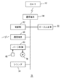
- FIG. 5 shows a control system of the purge device 20, the control unit 62 controls the purge device 20, and the communication terminal device 64 communicates with the overhead traveling vehicle 12 to prevent interference between the local carriage 22 and the overhead traveling vehicle 12. To do.
- the communication terminal device 66 communicates with a host controller (not shown), and receives an instruction related to conveyance in the purge device 20 and an instruction related to necessity of purging the cassette.
- the purge control unit 68 detects that the cassette is placed on the slide shelf in a state in which purging is possible by the load sensor 45 in accordance with an instruction from the control unit 62, piping of N 2 gas (purge gas) from the ceiling
- the purge valve is supplied to the air supply nozzle by opening the electromagnetic valve 70 provided in the air supply. Further, the local carriage 22 and the cylinder 34 are operated according to an instruction from the control unit 62.
- the operation of the embodiment will be described.
- the inside of the cassette 6 transferred from the overhead traveling vehicle 12 or the load port 4 to the shelves 28 and 30 is purged with N 2 gas or the like.
- purge gas is supplied from the air supply nozzle 46 and exhausted from the exhaust nozzle 48.
- the atmosphere in the cassette 6 is replaced with a purge gas to prevent the semiconductor wafer from being oxidized or contaminated.
- the cassette 6 includes a valve (not shown). The valve is opened by pressure from the nozzles 46 and 48, and when the pressure is lost, the valve is closed and airtight.
- the slide shelf 28 Since the slide shelf 28 is provided directly above the load port 4, it can be unloaded to the load port 4 quickly. Moreover, since it can also provide in the position which faces the load port 4, the number of the shelves per length of the traveling rail 24 can be increased.
- the unloading from the fixed shelf 30 requires the traveling of the local carriage 22 and the unloading operation, but the unloading from the slide shelf 28 does not require the traveling of the local carriage 22. That is, when the local carriage 22 chucks the cassette 6, the slide shelf 28 is quickly retracted to the side, and the local carriage 22 can start unloading without running. Therefore, if the cassette to be unloaded to the load port 4 is preferentially stored on the slide shelf 28, the cassette 6 can be unloaded to the load port 4 quickly.
- FIG. 6 shows a second embodiment, in which the same reference numerals as those in FIGS. 1 to 5 denote the same components, and are the same as those in the embodiments of FIGS.
- an overhead traveling vehicle system 72 that transports cassettes having different production management attributes such as hot lots is added. 75 are arranged in parallel. If the overhead traveling vehicle 12 can directly enter the bay 77 from the traveling rail 75 of the overhead traveling vehicle system 72, branching and merging of the traveling rails become complicated. Therefore, conveyors 78 and 79 are provided so as to pass under the traveling rails 74, 75, and 10. The conveyor 78 is for transportation into the bay 77, and the conveyor 79 is for transportation to the overhead traveling vehicle system 72 outside the bay 77. It is.
- a loop-like traveling rail 76 is provided so as to pass over the slide shelves 28 of the plurality of purge devices 20, and a transport carriage such as the overhead traveling vehicle 12 is caused to travel from the slide shelf 28 to the conveyor 78, 79, up to the overhead traveling vehicle system 72 is connected.
- 80 is a buffer, and the overhead traveling vehicle 12 traveling on the traveling rail 76 transfers the cassette to the buffer 80 by the lateral feed device 13 of FIG.
- the buffer 80 may or may not have a purge function using N 2 gas.
- the overhead traveling vehicle 12 traveling on the traveling rail 76 and the overhead traveling vehicle system 72 are a cassette that accommodates wafers of hot lots that are urgently transported, empty cassettes, cassettes that accommodate wafers that do not become products for process management or inspection. , Etc., and these cassettes are referred to as cassettes having different production management attributes.
- the conveyors 78 and 79 connect the overhead traveling vehicle system 72 of the inter-bay route and the overhead traveling vehicle traveling on the traveling rail 76 in the bay 77. Further, the system of the traveling rail 76 and the overhead traveling vehicle 12 can be changed to an arbitrary system capable of transporting the cassette in the ceiling space.
- a gantry crane that moves two-dimensionally in the bay 77, a transport carriage that runs on grid rails arranged in a grid in the bay 77, or a floor surface that is provided in the bay 77 and does not block the flow of clean air. It is possible to use an automated guided vehicle traveling on the road. All these systems are provided at a position higher than the purge device 20.
- the cassette when the cassette is transported from the processing apparatus 2a to the processing apparatus 2b, the cassette is purged by the purge apparatus 20a facing the processing apparatus 2a and then transferred to the purge apparatus 20b on the processing apparatus 2b side. It is possible to perform processing after purging again with the purge device 20b on the 2b side.
- a buffer 80 is provided to improve the storage capacity in the bay.
- the container to be purged is not limited to a cassette, and the goods to be stored may be medicines, foods, etc. in addition to semiconductor wafers.
Landscapes
- Engineering & Computer Science (AREA)
- Mechanical Engineering (AREA)
- Container, Conveyance, Adherence, Positioning, Of Wafer (AREA)
- Warehouses Or Storage Devices (AREA)
- Robotics (AREA)
- Carriers, Traveling Bodies, And Overhead Traveling Cranes (AREA)
Abstract
Description
走行が自在でかつ容器を昇降させるホイストを備えるローカル台車と、
天井走行車の走行レールの下方でかつ容器受け渡し先の上方に設けられている、ローカル台車の走行レールと、
ローカル台車の走行レールの下方で、かつ容器受け渡し先の直上部を塞がないように設けられ、容器を載置自在なパージ台と、
パージ台に載置されている容器へパージガスを供給するパージガス供給装置、
とを備えている。
天井走行車の走行レールの下方でかつ容器受け渡し先の上方に設けられている、ローカル台車の走行レールと、
ローカル台車の走行レールの下方で、かつ容器受け渡し先の直上部を塞がないように設けられ、容器を載置自在なパージ台と、
パージ台に載置されている容器へパージガスを供給するパージガス供給装置、とを備えているパージ装置により、
天井走行車と容器受け渡し先との間で、容器をパージ台に一時的に載置し、パージガス供給装置により容器をパージガスでパージする。
スライド棚は、固定部上の位置と容器受け渡し先の直上部との間で、スライド自在であり、
パージガス供給装置は、スライド棚に設けられかつ容器内へパージガスを供給する給気ノズルと、固定部から給気ノズルへパージガスを供給する配管とを備え、
配管は屈曲自在な屈曲部を備え、
スライド棚と固定部との間には、屈曲部を屈曲自在に支持するケーブルガイドが設けられている。
ケーブルガイドに、荷重センサの電源線と信号線が、配管と共に支持されている。
8,72 天井走行車システム 10 走行レール
12 天井走行車 13 横送り装置 14 回動装置
15 昇降装置 16 昇降台 20 パージ装置
22 ローカル台車 24 走行レール 26 開口
28 スライド棚 29 固定部 30 固定棚 31 支柱
32 ガイド 33 プレート 34 シリンダ
36 ピストン 38 ミドル部 40 トップ部
42 カップリングピン 44 着座センサ 45 荷重センサ
46 給気ノズル 48 排気ノズル 50,52 配管
54 ケーブルガイド 56 走行部 58 昇降装置
60 昇降台 62 制御部 64,66 通信端末
68 パージ制御部 70 電磁弁 74~76 走行レール
77 ベイ 78,79 コンベヤ 80 バッファ
Claims (8)
- 天井走行車と容器受け渡し先との間で容器をパージガスによりパージする装置であって、
走行が自在でかつ容器を昇降させるホイストを備えるローカル台車と、
天井走行車の走行レールの下方でかつ容器受け渡し先の上方に設けられている、ローカル台車の走行レールと、
ローカル台車の走行レールの下方で、かつ容器受け渡し先の直上部を塞がないように設けられ、容器を載置自在なパージ台と、
パージ台に載置されている容器へパージガスを供給するパージガス供給装置、
とを備えているパージ装置。 - 前記パージ台は、容器受け渡し位置の直上部とは異なる位置と前記直上部との間でスライド自在なスライド棚を備えていることを特徴とする、請求項1のパージ装置。
- 前記パージ台として、前記スライド棚以外に固定の棚が設けられ、
さらに前記受け渡し先へ渡す容器を優先的に前記スライド棚でパージするように、容器を載置するパージ台を選択して、ローカル台車を制御する制御部を備えていることを特徴とする、請求項2のパージ装置。 - クリーンルームの天井部に設置され、かつ前記天井部からパージガスの供給を受けるように構成されていることを特徴とする、請求項1~3のいずれかのパージ装置。
- 前記容器は半導体ウェハーを収納するカセットであり、
かつ前記受け渡し先は半導体の処理装置のロードポートであることを特徴とする、請求項1~4のいずれかのパージ装置。 - 前記パージ台は、容器受け渡し先の直上部とは異なる位置に、固定部をさらに備え、
前記スライド棚は、固定部上の位置と容器受け渡し先の直上部との間で、スライド自在であり、
前記パージガス供給装置は、前記スライド棚に設けられかつ容器内へパージガスを供給する給気ノズルと、前記固定部から前記給気ノズルへパージガスを供給する配管とを備え、
前記配管は屈曲自在な屈曲部を備え、
前記スライド棚と前記固定部との間には、前記屈曲部を屈曲自在に支持するケーブルガイドが設けられていることを特徴とする、請求項2のパージ装置。 - 前記スライド棚上に容器からの荷重を検出する荷重センサが設けられて、前記荷重センサにより容器からの荷重を検出すると、前記給気ノズルからパージガスを供給するように、前記パージガス供給装置が構成され、
前記ケーブルガイドに、荷重センサの電源線と信号線が、前記配管と共に支持されていることを特徴とする、請求項6のパージ装置。 - 走行が自在でかつ容器を昇降させるホイストを備えるローカル台車と、
天井走行車の走行レールの下方でかつ容器受け渡し先の上方に設けられている、ローカル台車の走行レールと、
ローカル台車の走行レールの下方で、かつ容器受け渡し先の直上部を塞がないように設けられ、容器を載置自在なパージ台と、
パージ台に載置されている容器へパージガスを供給するパージガス供給装置、とを備えているパージ装置により、
天井走行車と容器受け渡し先との間で、容器をパージ台に一時的に載置し、パージガス供給装置により容器をパージガスでパージするパージ方法。
Priority Applications (8)
| Application Number | Priority Date | Filing Date | Title |
|---|---|---|---|
| CN201580047207.7A CN106796908B (zh) | 2014-09-25 | 2015-07-23 | 清洗装置以及清洗方法 |
| JP2016550006A JP6241693B2 (ja) | 2014-09-25 | 2015-07-23 | パージ装置及びパージ方法 |
| US15/508,503 US10325797B2 (en) | 2014-09-25 | 2015-07-23 | Purging device and purging method |
| IL250119A IL250119A (en) | 2014-09-25 | 2015-07-23 | Device and purification method |
| EP15845065.0A EP3200221B1 (en) | 2014-09-25 | 2015-07-23 | Purging device and purging method |
| SG11201700643UA SG11201700643UA (en) | 2014-09-25 | 2015-07-23 | Purging device and purging method |
| KR1020177010018A KR20170058393A (ko) | 2014-09-25 | 2015-07-23 | 퍼지 장치 및 퍼지 방법 |
| KR1020187035642A KR101942394B1 (ko) | 2014-09-25 | 2015-07-23 | 퍼지 장치 및 퍼지 방법 |
Applications Claiming Priority (2)
| Application Number | Priority Date | Filing Date | Title |
|---|---|---|---|
| JP2014-195152 | 2014-09-25 | ||
| JP2014195152 | 2014-09-25 |
Publications (1)
| Publication Number | Publication Date |
|---|---|
| WO2016047260A1 true WO2016047260A1 (ja) | 2016-03-31 |
Family
ID=55580794
Family Applications (1)
| Application Number | Title | Priority Date | Filing Date |
|---|---|---|---|
| PCT/JP2015/071011 Ceased WO2016047260A1 (ja) | 2014-09-25 | 2015-07-23 | パージ装置及びパージ方法 |
Country Status (9)
| Country | Link |
|---|---|
| US (1) | US10325797B2 (ja) |
| EP (1) | EP3200221B1 (ja) |
| JP (1) | JP6241693B2 (ja) |
| KR (2) | KR20170058393A (ja) |
| CN (1) | CN106796908B (ja) |
| IL (1) | IL250119A (ja) |
| SG (1) | SG11201700643UA (ja) |
| TW (1) | TWI667437B (ja) |
| WO (1) | WO2016047260A1 (ja) |
Cited By (2)
| Publication number | Priority date | Publication date | Assignee | Title |
|---|---|---|---|---|
| KR101852323B1 (ko) * | 2016-07-05 | 2018-04-26 | 로체 시스템즈(주) | 퍼지 모듈 지그 및 이를 포함한 퍼지 모듈 |
| JP2022126900A (ja) * | 2021-02-19 | 2022-08-31 | 株式会社ダイフク | 搬送設備 |
Families Citing this family (13)
| Publication number | Priority date | Publication date | Assignee | Title |
|---|---|---|---|---|
| WO2016047260A1 (ja) * | 2014-09-25 | 2016-03-31 | 村田機械株式会社 | パージ装置及びパージ方法 |
| EP3336018B1 (en) * | 2015-08-14 | 2021-12-15 | Murata Machinery, Ltd. | Conveyance system |
| KR102062548B1 (ko) * | 2015-12-08 | 2020-01-06 | 무라다기카이가부시끼가이샤 | 반송 시스템 및 반송 방법 |
| FR3080949B1 (fr) * | 2018-05-04 | 2021-05-28 | St Microelectronics Rousset | Dispositif de memoire non volatile du type a piegeage de charges et procede de fabrication |
| KR102453738B1 (ko) * | 2018-06-15 | 2022-10-12 | 무라다기카이가부시끼가이샤 | 보관 선반 |
| JP7067621B2 (ja) * | 2018-07-20 | 2022-05-16 | 村田機械株式会社 | 保管棚及び保管棚の設置方法 |
| KR102530860B1 (ko) * | 2018-12-26 | 2023-05-10 | 무라다기카이가부시끼가이샤 | 보관 시스템 |
| EP3915902B1 (en) * | 2019-01-25 | 2024-04-03 | Murata Machinery, Ltd. | Transport system |
| JP7224725B2 (ja) * | 2019-03-26 | 2023-02-20 | 株式会社ディスコ | 搬送システム |
| US20220375774A1 (en) * | 2019-11-05 | 2022-11-24 | Murata Machinery, Ltd. | Transport vehicle system |
| CN116529180A (zh) * | 2020-11-12 | 2023-08-01 | 村田机械株式会社 | 保管架 |
| KR102593950B1 (ko) * | 2021-12-29 | 2023-10-24 | 세메스 주식회사 | 유량공급장치 및 공급방법 |
| JP2025009152A (ja) * | 2023-07-07 | 2025-01-20 | 株式会社ディスコ | 搬送車 |
Citations (2)
| Publication number | Priority date | Publication date | Assignee | Title |
|---|---|---|---|---|
| JP2012114406A (ja) * | 2010-11-04 | 2012-06-14 | Muratec Automation Co Ltd | 搬送システム及び搬送方法 |
| WO2012160917A1 (ja) * | 2011-05-25 | 2012-11-29 | 村田機械株式会社 | ロードポート装置、搬送システム、及びコンテナ搬出方法 |
Family Cites Families (10)
| Publication number | Priority date | Publication date | Assignee | Title |
|---|---|---|---|---|
| US20080240892A1 (en) * | 2007-03-28 | 2008-10-02 | International Business Machines Corporation | Storage buffer device for automated material handling systems |
| KR101077566B1 (ko) * | 2008-08-20 | 2011-10-28 | 세메스 주식회사 | 기판 처리장치 및 이의 기판 이송 방법 |
| JP4807424B2 (ja) * | 2009-03-17 | 2011-11-02 | 村田機械株式会社 | 天井搬送システムと物品の移載方法 |
| US8882433B2 (en) * | 2009-05-18 | 2014-11-11 | Brooks Automation, Inc. | Integrated systems for interfacing with substrate container storage systems |
| CN102460675B (zh) * | 2009-05-18 | 2015-04-29 | 布鲁克斯自动化公司 | 与基片容器存储系统交接的集成系统 |
| JP5429570B2 (ja) * | 2010-03-08 | 2014-02-26 | 株式会社ダイフク | 物品搬送設備 |
| JP5229363B2 (ja) | 2010-11-04 | 2013-07-03 | 村田機械株式会社 | 搬送システム及び搬送方法 |
| KR101418812B1 (ko) * | 2012-10-31 | 2014-07-16 | 크린팩토메이션 주식회사 | 웨이퍼 퍼지 가능한 천장 보관 장치 |
| US10319621B2 (en) * | 2012-12-31 | 2019-06-11 | Asm Ip Holding B.V. | Semiconductor processing assembly and facility |
| WO2016047260A1 (ja) * | 2014-09-25 | 2016-03-31 | 村田機械株式会社 | パージ装置及びパージ方法 |
-
2015
- 2015-07-23 WO PCT/JP2015/071011 patent/WO2016047260A1/ja not_active Ceased
- 2015-07-23 IL IL250119A patent/IL250119A/en active IP Right Grant
- 2015-07-23 JP JP2016550006A patent/JP6241693B2/ja active Active
- 2015-07-23 US US15/508,503 patent/US10325797B2/en active Active
- 2015-07-23 KR KR1020177010018A patent/KR20170058393A/ko not_active Ceased
- 2015-07-23 SG SG11201700643UA patent/SG11201700643UA/en unknown
- 2015-07-23 CN CN201580047207.7A patent/CN106796908B/zh active Active
- 2015-07-23 EP EP15845065.0A patent/EP3200221B1/en active Active
- 2015-07-23 KR KR1020187035642A patent/KR101942394B1/ko active Active
- 2015-09-23 TW TW104131471A patent/TWI667437B/zh active
Patent Citations (2)
| Publication number | Priority date | Publication date | Assignee | Title |
|---|---|---|---|---|
| JP2012114406A (ja) * | 2010-11-04 | 2012-06-14 | Muratec Automation Co Ltd | 搬送システム及び搬送方法 |
| WO2012160917A1 (ja) * | 2011-05-25 | 2012-11-29 | 村田機械株式会社 | ロードポート装置、搬送システム、及びコンテナ搬出方法 |
Non-Patent Citations (1)
| Title |
|---|
| See also references of EP3200221A4 * |
Cited By (5)
| Publication number | Priority date | Publication date | Assignee | Title |
|---|---|---|---|---|
| KR101852323B1 (ko) * | 2016-07-05 | 2018-04-26 | 로체 시스템즈(주) | 퍼지 모듈 지그 및 이를 포함한 퍼지 모듈 |
| US10395948B2 (en) | 2016-07-05 | 2019-08-27 | Rorze Systems Corporation | Purge module jig and purge module having the same |
| JP2022126900A (ja) * | 2021-02-19 | 2022-08-31 | 株式会社ダイフク | 搬送設備 |
| JP7327425B2 (ja) | 2021-02-19 | 2023-08-16 | 株式会社ダイフク | 搬送設備 |
| US12280952B2 (en) | 2021-02-19 | 2025-04-22 | Daifuku Co., Ltd. | Transfer system |
Also Published As
| Publication number | Publication date |
|---|---|
| EP3200221B1 (en) | 2021-05-05 |
| JP6241693B2 (ja) | 2017-12-06 |
| CN106796908B (zh) | 2019-11-26 |
| SG11201700643UA (en) | 2017-04-27 |
| IL250119A0 (en) | 2017-03-30 |
| EP3200221A4 (en) | 2018-05-16 |
| EP3200221A1 (en) | 2017-08-02 |
| TW201612472A (en) | 2016-04-01 |
| KR20170058393A (ko) | 2017-05-26 |
| KR101942394B1 (ko) | 2019-01-25 |
| US10325797B2 (en) | 2019-06-18 |
| IL250119A (en) | 2017-05-29 |
| TWI667437B (zh) | 2019-08-01 |
| CN106796908A (zh) | 2017-05-31 |
| US20170278736A1 (en) | 2017-09-28 |
| KR20180135090A (ko) | 2018-12-19 |
| JPWO2016047260A1 (ja) | 2017-06-15 |
Similar Documents
| Publication | Publication Date | Title |
|---|---|---|
| JP6241693B2 (ja) | パージ装置及びパージ方法 | |
| JP6048686B2 (ja) | 一時保管装置と搬送システム及び一時保管方法 | |
| TWI722208B (zh) | 搬送系統 | |
| KR101495629B1 (ko) | 로드 포트 장치, 반송 시스템 및 컨테이너 반출 방법 | |
| JP6252676B2 (ja) | キャリアの一時保管装置及び一時保管方法 | |
| JP6206748B2 (ja) | キャリアの搬送システムと搬送方法 | |
| CN102530553A (zh) | 搬送系统以及搬送方法 | |
| TWI691446B (zh) | 容器搬送設備 | |
| JPWO2015194267A6 (ja) | キャリアの搬送システムと搬送方法 | |
| CN106463441A (zh) | 载具的临时保管装置和临时保管方法 | |
| JP4200387B2 (ja) | 搬送システム | |
| JP2008019017A (ja) | 物品収納装置 | |
| KR20240096121A (ko) | 물류 반송 설비 및 물류 반송 방법 | |
| JP2002060007A (ja) | 搬送システム |
Legal Events
| Date | Code | Title | Description |
|---|---|---|---|
| 121 | Ep: the epo has been informed by wipo that ep was designated in this application |
Ref document number: 15845065 Country of ref document: EP Kind code of ref document: A1 |
|
| WWE | Wipo information: entry into national phase |
Ref document number: 250119 Country of ref document: IL |
|
| ENP | Entry into the national phase |
Ref document number: 2016550006 Country of ref document: JP Kind code of ref document: A |
|
| WWE | Wipo information: entry into national phase |
Ref document number: 15508503 Country of ref document: US |
|
| REEP | Request for entry into the european phase |
Ref document number: 2015845065 Country of ref document: EP |
|
| WWE | Wipo information: entry into national phase |
Ref document number: 2015845065 Country of ref document: EP |
|
| NENP | Non-entry into the national phase |
Ref country code: DE |
|
| ENP | Entry into the national phase |
Ref document number: 20177010018 Country of ref document: KR Kind code of ref document: A |