WO2016052156A1 - 断熱配管 - Google Patents
断熱配管 Download PDFInfo
- Publication number
- WO2016052156A1 WO2016052156A1 PCT/JP2015/075994 JP2015075994W WO2016052156A1 WO 2016052156 A1 WO2016052156 A1 WO 2016052156A1 JP 2015075994 W JP2015075994 W JP 2015075994W WO 2016052156 A1 WO2016052156 A1 WO 2016052156A1
- Authority
- WO
- WIPO (PCT)
- Prior art keywords
- pipe
- heat
- heat insulating
- heat insulation
- piping
- Prior art date
- Legal status (The legal status is an assumption and is not a legal conclusion. Google has not performed a legal analysis and makes no representation as to the accuracy of the status listed.)
- Ceased
Links
Images


Classifications
-
- F—MECHANICAL ENGINEERING; LIGHTING; HEATING; WEAPONS; BLASTING
- F16—ENGINEERING ELEMENTS AND UNITS; GENERAL MEASURES FOR PRODUCING AND MAINTAINING EFFECTIVE FUNCTIONING OF MACHINES OR INSTALLATIONS; THERMAL INSULATION IN GENERAL
- F16L—PIPES; JOINTS OR FITTINGS FOR PIPES; SUPPORTS FOR PIPES, CABLES OR PROTECTIVE TUBING; MEANS FOR THERMAL INSULATION IN GENERAL
- F16L59/00—Thermal insulation in general
- F16L59/02—Shape or form of insulating materials, with or without coverings integral with the insulating materials
- F16L59/021—Shape or form of insulating materials, with or without coverings integral with the insulating materials comprising a single piece or sleeve, e.g. split sleeves; consisting of two half sleeves; comprising more than two segments
- F16L59/022—Shape or form of insulating materials, with or without coverings integral with the insulating materials comprising a single piece or sleeve, e.g. split sleeves; consisting of two half sleeves; comprising more than two segments with a single slit
-
- F—MECHANICAL ENGINEERING; LIGHTING; HEATING; WEAPONS; BLASTING
- F01—MACHINES OR ENGINES IN GENERAL; ENGINE PLANTS IN GENERAL; STEAM ENGINES
- F01N—GAS-FLOW SILENCERS OR EXHAUST APPARATUS FOR MACHINES OR ENGINES IN GENERAL; GAS-FLOW SILENCERS OR EXHAUST APPARATUS FOR INTERNAL-COMBUSTION ENGINES
- F01N13/00—Exhaust or silencing apparatus characterised by constructional features
- F01N13/14—Exhaust or silencing apparatus characterised by constructional features having thermal insulation
-
- F—MECHANICAL ENGINEERING; LIGHTING; HEATING; WEAPONS; BLASTING
- F01—MACHINES OR ENGINES IN GENERAL; ENGINE PLANTS IN GENERAL; STEAM ENGINES
- F01N—GAS-FLOW SILENCERS OR EXHAUST APPARATUS FOR MACHINES OR ENGINES IN GENERAL; GAS-FLOW SILENCERS OR EXHAUST APPARATUS FOR INTERNAL-COMBUSTION ENGINES
- F01N3/00—Exhaust or silencing apparatus having means for purifying, rendering innocuous, or otherwise treating exhaust
- F01N3/08—Exhaust or silencing apparatus having means for purifying, rendering innocuous, or otherwise treating exhaust for rendering innocuous
- F01N3/10—Exhaust or silencing apparatus having means for purifying, rendering innocuous, or otherwise treating exhaust for rendering innocuous by thermal or catalytic conversion of noxious components of exhaust
- F01N3/18—Exhaust or silencing apparatus having means for purifying, rendering innocuous, or otherwise treating exhaust for rendering innocuous by thermal or catalytic conversion of noxious components of exhaust characterised by methods of operation; Control
- F01N3/20—Exhaust or silencing apparatus having means for purifying, rendering innocuous, or otherwise treating exhaust for rendering innocuous by thermal or catalytic conversion of noxious components of exhaust characterised by methods of operation; Control specially adapted for catalytic conversion
- F01N3/206—Adding periodically or continuously substances to exhaust gases for promoting purification, e.g. catalytic material in liquid form, NOx reducing agents
- F01N3/2066—Selective catalytic reduction [SCR]
-
- F—MECHANICAL ENGINEERING; LIGHTING; HEATING; WEAPONS; BLASTING
- F01—MACHINES OR ENGINES IN GENERAL; ENGINE PLANTS IN GENERAL; STEAM ENGINES
- F01N—GAS-FLOW SILENCERS OR EXHAUST APPARATUS FOR MACHINES OR ENGINES IN GENERAL; GAS-FLOW SILENCERS OR EXHAUST APPARATUS FOR INTERNAL-COMBUSTION ENGINES
- F01N3/00—Exhaust or silencing apparatus having means for purifying, rendering innocuous, or otherwise treating exhaust
- F01N3/08—Exhaust or silencing apparatus having means for purifying, rendering innocuous, or otherwise treating exhaust for rendering innocuous
- F01N3/10—Exhaust or silencing apparatus having means for purifying, rendering innocuous, or otherwise treating exhaust for rendering innocuous by thermal or catalytic conversion of noxious components of exhaust
- F01N3/24—Exhaust or silencing apparatus having means for purifying, rendering innocuous, or otherwise treating exhaust for rendering innocuous by thermal or catalytic conversion of noxious components of exhaust characterised by constructional aspects of converting apparatus
- F01N3/26—Construction of thermal reactors
-
- F—MECHANICAL ENGINEERING; LIGHTING; HEATING; WEAPONS; BLASTING
- F16—ENGINEERING ELEMENTS AND UNITS; GENERAL MEASURES FOR PRODUCING AND MAINTAINING EFFECTIVE FUNCTIONING OF MACHINES OR INSTALLATIONS; THERMAL INSULATION IN GENERAL
- F16L—PIPES; JOINTS OR FITTINGS FOR PIPES; SUPPORTS FOR PIPES, CABLES OR PROTECTIVE TUBING; MEANS FOR THERMAL INSULATION IN GENERAL
- F16L53/00—Heating of pipes or pipe systems; Cooling of pipes or pipe systems
- F16L53/30—Heating of pipes or pipe systems
- F16L53/32—Heating of pipes or pipe systems using hot fluids
-
- F—MECHANICAL ENGINEERING; LIGHTING; HEATING; WEAPONS; BLASTING
- F16—ENGINEERING ELEMENTS AND UNITS; GENERAL MEASURES FOR PRODUCING AND MAINTAINING EFFECTIVE FUNCTIONING OF MACHINES OR INSTALLATIONS; THERMAL INSULATION IN GENERAL
- F16L—PIPES; JOINTS OR FITTINGS FOR PIPES; SUPPORTS FOR PIPES, CABLES OR PROTECTIVE TUBING; MEANS FOR THERMAL INSULATION IN GENERAL
- F16L59/00—Thermal insulation in general
- F16L59/02—Shape or form of insulating materials, with or without coverings integral with the insulating materials
-
- F—MECHANICAL ENGINEERING; LIGHTING; HEATING; WEAPONS; BLASTING
- F16—ENGINEERING ELEMENTS AND UNITS; GENERAL MEASURES FOR PRODUCING AND MAINTAINING EFFECTIVE FUNCTIONING OF MACHINES OR INSTALLATIONS; THERMAL INSULATION IN GENERAL
- F16L—PIPES; JOINTS OR FITTINGS FOR PIPES; SUPPORTS FOR PIPES, CABLES OR PROTECTIVE TUBING; MEANS FOR THERMAL INSULATION IN GENERAL
- F16L59/00—Thermal insulation in general
- F16L59/14—Arrangements for the insulation of pipes or pipe systems
-
- F—MECHANICAL ENGINEERING; LIGHTING; HEATING; WEAPONS; BLASTING
- F16—ENGINEERING ELEMENTS AND UNITS; GENERAL MEASURES FOR PRODUCING AND MAINTAINING EFFECTIVE FUNCTIONING OF MACHINES OR INSTALLATIONS; THERMAL INSULATION IN GENERAL
- F16L—PIPES; JOINTS OR FITTINGS FOR PIPES; SUPPORTS FOR PIPES, CABLES OR PROTECTIVE TUBING; MEANS FOR THERMAL INSULATION IN GENERAL
- F16L9/00—Rigid pipes
- F16L9/18—Double-walled pipes; Multi-channel pipes or pipe assemblies
- F16L9/19—Multi-channel pipes or pipe assemblies
- F16L9/20—Pipe assemblies
-
- F—MECHANICAL ENGINEERING; LIGHTING; HEATING; WEAPONS; BLASTING
- F01—MACHINES OR ENGINES IN GENERAL; ENGINE PLANTS IN GENERAL; STEAM ENGINES
- F01N—GAS-FLOW SILENCERS OR EXHAUST APPARATUS FOR MACHINES OR ENGINES IN GENERAL; GAS-FLOW SILENCERS OR EXHAUST APPARATUS FOR INTERNAL-COMBUSTION ENGINES
- F01N2260/00—Exhaust treating devices having provisions not otherwise provided for
- F01N2260/20—Exhaust treating devices having provisions not otherwise provided for for heat or sound protection, e.g. using a shield or specially shaped outer surface of exhaust device
-
- F—MECHANICAL ENGINEERING; LIGHTING; HEATING; WEAPONS; BLASTING
- F01—MACHINES OR ENGINES IN GENERAL; ENGINE PLANTS IN GENERAL; STEAM ENGINES
- F01N—GAS-FLOW SILENCERS OR EXHAUST APPARATUS FOR MACHINES OR ENGINES IN GENERAL; GAS-FLOW SILENCERS OR EXHAUST APPARATUS FOR INTERNAL-COMBUSTION ENGINES
- F01N2610/00—Adding substances to exhaust gases
- F01N2610/02—Adding substances to exhaust gases the substance being ammonia or urea
-
- F—MECHANICAL ENGINEERING; LIGHTING; HEATING; WEAPONS; BLASTING
- F01—MACHINES OR ENGINES IN GENERAL; ENGINE PLANTS IN GENERAL; STEAM ENGINES
- F01N—GAS-FLOW SILENCERS OR EXHAUST APPARATUS FOR MACHINES OR ENGINES IN GENERAL; GAS-FLOW SILENCERS OR EXHAUST APPARATUS FOR INTERNAL-COMBUSTION ENGINES
- F01N2610/00—Adding substances to exhaust gases
- F01N2610/10—Adding substances to exhaust gases the substance being heated, e.g. by heating tank or supply line of the added substance
-
- F—MECHANICAL ENGINEERING; LIGHTING; HEATING; WEAPONS; BLASTING
- F01—MACHINES OR ENGINES IN GENERAL; ENGINE PLANTS IN GENERAL; STEAM ENGINES
- F01N—GAS-FLOW SILENCERS OR EXHAUST APPARATUS FOR MACHINES OR ENGINES IN GENERAL; GAS-FLOW SILENCERS OR EXHAUST APPARATUS FOR INTERNAL-COMBUSTION ENGINES
- F01N2610/00—Adding substances to exhaust gases
- F01N2610/14—Arrangements for the supply of substances, e.g. conduits
- F01N2610/1473—Overflow or return means for the substances, e.g. conduits or valves for the return path
-
- Y—GENERAL TAGGING OF NEW TECHNOLOGICAL DEVELOPMENTS; GENERAL TAGGING OF CROSS-SECTIONAL TECHNOLOGIES SPANNING OVER SEVERAL SECTIONS OF THE IPC; TECHNICAL SUBJECTS COVERED BY FORMER USPC CROSS-REFERENCE ART COLLECTIONS [XRACs] AND DIGESTS
- Y02—TECHNOLOGIES OR APPLICATIONS FOR MITIGATION OR ADAPTATION AGAINST CLIMATE CHANGE
- Y02T—CLIMATE CHANGE MITIGATION TECHNOLOGIES RELATED TO TRANSPORTATION
- Y02T10/00—Road transport of goods or passengers
- Y02T10/10—Internal combustion engine [ICE] based vehicles
- Y02T10/12—Improving ICE efficiencies
Definitions
- the present invention relates to a heat insulating pipe.
- an exhaust gas purification device (hereinafter referred to as an SCR system) that uses an SCR (Selective Catalytic Reduction) catalyst to purify NOx.
- an injection nozzle for injecting urea water into an exhaust pipe through which exhaust gas discharged from the engine flows, and an SCR catalyst disposed downstream of the injection nozzle are provided.
- urea water is injected into the high-temperature exhaust gas flowing through the exhaust pipe, and urea is hydrolyzed by the heat of the exhaust gas to generate ammonia.
- the produced ammonia flows through the exhaust pipe together with the exhaust gas downstream, and reaches the SCR catalyst.
- the chemical reaction between ammonia and NOx in the exhaust gas is promoted by the action of the SCR catalyst, and the NOx is purified into water and nitrogen.
- Patent Document 1 discloses a liquid transfer pipe in which a connection portion between a pipe joint and a pipe and a pipe in the vicinity thereof are covered with a heat radiation prevention cover and a code heater is inserted into the pipe.
- the exhaust pipe Since the exhaust pipe is close to an engine that generates high heat, the ambient temperature is very high near the pipe connected to the exhaust pipe. For this reason, the urea water in the pipe is heated by exchanging heat with the atmosphere and is heated to an allowable temperature or more, and the concentration of moisture may be excessively increased due to evaporation of moisture, or ammonia may be generated.
- a heat shield was installed between the pipe and the heat source in order to suppress the temperature rise of the urea water, but the effect was not sufficient.
- an object of the present invention is to provide a heat insulating pipe that can suppress a temperature rise in the pipe due to heat exchange with the atmosphere.
- the heat insulating pipe of the present invention includes a pipe through which a fluid can flow and a heat insulating member disposed so as to cover the pipe, and the pipe is used in an exhaust gas purification apparatus using an SCR catalyst, and the heat insulating member However, it has a closed cell structure, and can suppress an increase in temperature of the fluid due to heat exchange with the atmosphere.
- the heat insulation pipe of the present invention includes a pipe through which a fluid can flow and a heat insulation member arranged so as to cover the pipe.
- the pipe is used in an exhaust gas purification apparatus using an SCR catalyst, and the heat insulation member is independent.
- the inside of the pipe is insulated from the outside by the heat insulating member so that the heat of the atmosphere can be reduced. It is possible to suppress the temperature rise of the fluid flowing through the inside of the pipe due to the replacement of the pipe.
- FIG. 2 is an end view showing an A-A ′ cross section in FIG. 1 of the heat insulating pipe according to the embodiment of the present invention. It is the schematic which shows the construction machine where the heat insulation piping which concerns on embodiment of this invention was used. It is the schematic of the apparatus for evaluating the heat insulation performance of the heat insulation piping which concerns on embodiment of this invention.
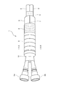
- a heat insulating pipe 1 shown in FIG. 1 includes a pipe 2 through which a fluid can flow and a heat insulating member 3 disposed so as to cover the pipe 2.
- the heat insulating pipe 1 is further provided with a hot water pipe 4 that is arranged along the pipe 2 and through which a fluid heated inside can be circulated.
- the pipe 2 and the hot water pipe 4 have flexibility and have a cylindrical shape.
- the material which forms the piping 2 and the hot water piping 4 is selected according to the liquid which distribute
- a material is selected so that urea water as a fluid can flow through the pipe 2 and an antifreeze liquid as a heated fluid can flow through the hot water pipe 4.
- the pipe 2 and the hot water pipe 4 are formed of resin.
- Such a pipe 2 and hot water pipe 4 are bundled together by a bundling member 5 and are fixed so that their side surfaces are in contact with each other.
- the bundling member 5 is a tape-like member, and the pipe 2 is wound around the surface spirally without a gap in a state where the side face of the pipe 2 and the side face of the hot water pipe 4 are in contact with each other. 2 and the hot water pipe 4 are fixed.
- the tape-shaped member does not have adhesiveness, but may have adhesiveness.
- the pipe 2 is provided with a joint 6a that facilitates connection with other equipment at one end, and a joint at the other end (not shown).
- the hot water pipe 4 also has a joint 6b at one end and a joint at the other end (not shown).
- the joints 6a and 6b are formed of resin and are female.
- the joint may be male.
- the pipe 2 and the hot water pipe 4 may have a joint only at one end or may not have a joint.
- the heat insulating member 3 is formed of a member having flexibility such as an elastomer having a closed cell structure in which adjacent bubbles are not connected and a plurality of independent bubbles are formed.
- the heat insulating member 3 is made of, for example, ethylene propylene diene synthetic rubber or nitrile synthetic rubber.
- the heat insulating member 3 has a hollow cylindrical shape, and a pipe 2 and a hot water pipe 4 are inserted into the hollow portion of the heat insulating member 3 so that the heat insulating member 3 covers the pipe 2 and the hot water pipe 4. It has become.
- the heat insulation member 3 is provided with the slit 7 along the major axis direction, and the pipe 2 and the hot water pipe 4 can be inserted into the inside through the slit 7.
- the heat insulating member 3 is covered with a protective member 8 having wear resistance in order to protect it from external damage.
- the protection member 8 is a tape-like member having high heat resistance and wear resistance, and is wound spirally around the surface of the heat insulating member 3 without a gap. Therefore, since the protection member 8 can protect the heat insulating member 3 from the damage, the heat insulating member 3 is prevented from being deteriorated in the heat insulating performance due to the damage.
- the heat insulating member 3 is further covered with a protective member 9 having stretchability and adhesiveness on the protective member 8 wound around the surface.
- the protection member 9 is a tape-like member having high stretchability, adhesiveness, and heat resistance, and is wound spirally around the surface of the protection member 8 without a gap. Therefore, since the protective member 8 is fixed by the protective member 9 and the protective member 8 is prevented from being peeled off, the heat insulating member 3 is protected from external damage, and a decrease in heat insulating performance is prevented.
- Protective members 8 and 9 are not particularly limited, but preferably have heat resistance. This is because the protective members 8 and 9 are not deteriorated even in a high-temperature atmosphere, and the functions possessed by them can be maintained. Therefore, the heat resistance of the heat insulating pipe 1 is improved, and the heat insulating pipe 1 can suppress a decrease in heat insulating performance even in a high-temperature atmosphere, and more reliably suppress an increase in the temperature of the fluid flowing through the pipe 2.
- the protective members 8 and 9 are tape-shaped members, but the shape is not particularly limited as long as the heat insulating member 3 can be protected.
- the protective members 8 and 9 may be tube-shaped members.
- the fixing member 10 is a tape-like member having adhesiveness, and the heat insulating member 3 is wound around the end of the heat insulating member 3 spirally without a gap, so that the heat insulating member 3 is wrapped around the pipe 2 and the hot water pipe 4. It is fixed.
- the heat insulating pipe 1 is provided with a heat insulating member 3 in which a pipe 2 and a hot water pipe 4 gathered together by a bundling member 5 are located at the center and a slit 7 is formed so as to cover the periphery thereof.
- the heat insulating member 3 is covered with a protective member 8 and the outside thereof is covered with a protective member 9.
- the gap 27 is formed between the pipe 2 and the hot water pipe 4 and the heat insulating member 3 which are grouped together, but the pipe 2 and the hot water pipe 4 and the heat insulating member 3 are in close contact with each other.
- the space 27 may be small.
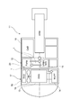
- the heat insulating pipe 1 is used in, for example, the SCR system 12 of the construction machine 11.
- the construction machine 11 is a machine used for construction work such as an excavator.
- the construction machine 11 includes an engine room 17 in which an engine 13, an exhaust pipe 14 through which exhaust gas discharged from the engine 13 flows, a radiator 15 that releases heat to the outside, and a cooling fan 16 that cools the radiator 15 are housed. And a cabin 18 on which a driver who controls the machine 11 enters.
- the SCR system 12 is disposed in a space between a cabin 18 provided in front of the aircraft and an engine room 17 provided in the rear of the aircraft.
- the engine 13 is connected to the radiator 15 via two pipes (not shown).
- the piping is provided with a pump (not shown) so that the antifreeze can be circulated between the engine 13 and the radiator 15.
- the antifreeze discharged from the radiator 15 by the pump flows through the piping and is supplied to the engine 13 to cool the engine 13.
- the antifreeze liquid heated by cooling the engine 13 is discharged from the engine 13, flows through the piping, and is supplied to the radiator 15.
- the heated antifreeze is cooled by the radiator 15 and supplied to the engine 13 again.
- the engine 13 is cooled by circulating the antifreeze liquid between the engine 13 and the radiator 15.
- the SCR system 12 includes a heat insulating pipe 1, an exhaust pipe 14, a urea water tank 19, and a pump 20.
- the exhaust pipe 14 includes an injection nozzle (not shown) that can inject urea water into the exhaust pipe 14.
- the exhaust pipe 14 further includes an SCR catalyst (not shown) downstream of the injection nozzle.
- the pump 20 is connected to the pipes 2 (FIG. 1) of the three heat insulating pipes 1. Among them, the other end of the pipe 2 of the two heat insulating pipes 1 is connected to the urea water tank 19. Therefore, the pump 20 can circulate urea water between the urea water tank 19 through the pipe 2. The other end of the remaining one heat insulating pipe 1 is connected to an injection nozzle. Therefore, the pump 20 can supply the urea water sucked from the urea water tank 19 to the injection nozzle via the pipe 2 and inject it into the exhaust pipe 14 from the injection nozzle.
- the antifreeze discharged from the engine 13 is supplied to one end of the hot water pipe 4 (FIG. 1) of the heat insulating pipe 1, the antifreeze flows through the hot water pipe 4, and the antifreeze discharged from the other end of the hot water pipe 4 It is configured to be supplied to the radiator 15. Therefore, in the SCR system 12, the urea water flowing through the pipe 2 in contact with the hot water pipe 4 is heated by exchanging heat with the antifreeze liquid flowing through the hot water pipe 4.
- the heat insulating pipe 1 connecting the pump 20 and the injection nozzle is disposed in the vicinity of the engine room 17 having a high atmospheric temperature. Further, the heat insulating pipe 1 is disposed in the vicinity of the engine 13 that is a heat source, and is in a place where the ambient temperature is higher in the engine room 17. For this reason, the heat insulating pipe 1 is very strongly affected by heat from the outside.
- urea water is injected into the high-temperature exhaust gas flowing through the exhaust pipe 14, and urea is hydrolyzed by the heat of the exhaust gas to generate ammonia.
- the produced ammonia flows downstream with the exhaust gas through the exhaust pipe 14 and reaches the SCR catalyst.
- the chemical reaction between ammonia and NOx in the exhaust gas is promoted by the action of the SCR catalyst, and the NOx is purified into water and nitrogen.
- the heat insulation piping 1 which concerns on embodiment of this invention in the above structure is equipped with the piping 2 which can distribute
- the heat insulating member 3 Used in the exhaust gas purifier, has a closed cell structure, and is configured to suppress an increase in the temperature of the fluid due to heat exchange with the atmosphere.
- the heat insulating pipe 1 is disposed in a place where the ambient temperature in the vicinity of the engine room 17 or the engine 13 is high, the inside of the pipe 2 is insulated from the outside by the heat insulating member 3, and the pipe is formed by exchanging heat with the atmosphere. The temperature rise of urea water flowing through the inside of 2 can be suppressed.
- the heat insulating member 1 can also deform the heat insulating member 3 following the shape of the heat insulating member 1 and reliably cover the pipe 2 with the heat insulating member 3 bent. Can do. Therefore, even when the heat insulating pipe 1 is arranged with the pipe 2 bent, the temperature rise of the urea water flowing through the pipe 2 can be more reliably suppressed.
- tube 1 can insert the piping 2 and the hot water piping 4 in the heat insulation member 3 from the slit 7 by providing the heat insulation member 3 with the slit 7 along a major axis direction, the heat insulation pipe
- the heat insulating pipe 1 fixes the pipe 2 and the hot water pipe 4 with the binding member 5, thereby increasing the area where the side face of the pipe 2 and the side face of the hot water pipe 4 are in contact with each other, and heat between the pipe 2 and the hot water pipe 4. Exchange efficiency can be improved and the temperature rise of the urea water which distribute
- the present invention is not limited to the above-described embodiment, and can be appropriately changed within the scope of the gist of the present invention.
- the materials and shapes of the pipe 2, the heat insulating member 3, the hot water pipe 4, the binding member 5, the fixing member 10, the joints 6a and 6b, and the protective members 8 and 9 can be changed as appropriate.
- the pipe 2 and the hot water pipe 4 are formed of resin, has flexibility, and has a cylindrical shape has been described.
- the present invention is not limited to this, and the pipe 2 and the hot water pipe 4 are used. May be formed of a material other than resin, may not have flexibility, and may have a cross-sectional shape other than a circle.
- the heat insulation member 3 was formed with the member which has a softness
- the heat insulation member 3 is soft. May not have the property, and the slit 7 may not be provided.
- the said embodiment demonstrated the case where the heat insulation piping 1 was equipped with the hot water piping 4, this invention is not restricted to this, The heat insulation piping 1 does not need to be equipped with the hot water piping 4.
- a heater wire for heating the fluid may be inserted into the pipe 2.
- the heat insulation member 3 is covered by the pipe 2 in the form close
- the heat insulation piping 1 demonstrated by the said embodiment may be provided with the corrugated tube.
- the pipe 2 and the hot water pipe 4 may be covered with a corrugated tube
- the corrugated tube may be further covered with a heat insulating member 3
- the heat insulating member 3 covering the pipe 2 and the hot water pipe 4 may be further covered with a corrugated tube.
- the position covered with the corrugated tube is not particularly limited.
- the corrugated tube may be formed with a slit along the long axis direction.
- the said embodiment demonstrated the case where the heat insulation member 3 of the heat insulation piping 1 was covered with the protection member 8 and the protection member 9, this invention is not limited to this.
- the heat insulation member 3 may be covered only with the protection member 8, may be covered only with the protection member 9, and may not be covered with the protection member.
- the heat insulating member 3 may include a closing member (not shown).
- the blocking member is disposed so as to cover a part of the surface of the heat insulating member 3 and fixes the heat insulating member 3 so that the slit 7 does not spread. Therefore, the heat insulating member 3 is fixed in a state where most of the slits 7 are closed.
- the closing member for example, a tape-like member (the same member as the protective member 9) having high stretchability, adhesiveness, and heat resistance can be used. In this case, for example, the closing member is stuck to a plurality of locations on the surface of the heat insulating member 3 so as to intersect with the slit 7 and is fixed in a state where the slit 7 is closed. Further, the closing member may be attached to the surface of the heat insulating member 3 so as to cover the entire slit 7.
- the heat insulating pipe 1 can reliably cover the pipe 2 with the heat insulating member 3 by fixing the heat insulating member 3 with the closing member so that the slit 7 is closed. Therefore, the heat insulation piping 1 can suppress the temperature rise of the urea water which distribute
- the heat insulation pipe 1 of Examples 1 to 6 having the cross-sectional shape shown in Table 1 was produced.
- the joints are connected to both ends of the pipe 2 having a length of 1 m, and the pipe 2 is covered with the heat insulating member 3 having a length of 0.95 m.
- the heat insulation pipe 1 is a resin tube (model number: TEU-4-8x6) as the pipe 2 and an aeroflex heat insulation tube having a slit 7 as the heat insulation member 3 (Examples 1 and 3 are model number: M10010, Example 2) Is manufactured using a tether tape (model number: 51026) having high heat resistance as the protective member 8.
- Example 2 after the piping 2 was covered with the corrugated tube 21 (size: 10 type) in which the slits 22 were formed, the corrugated tube 21 was covered with the heat insulating member 3, and the heat insulating piping 1 was produced.
- Example 3 after covering the pipe 2 with the heat insulating member 3, the heat insulating member 3 was covered with the corrugated tube 21 (size: 28 type) in which the slits 22 were formed, and the heat insulating pipe 1 was produced.
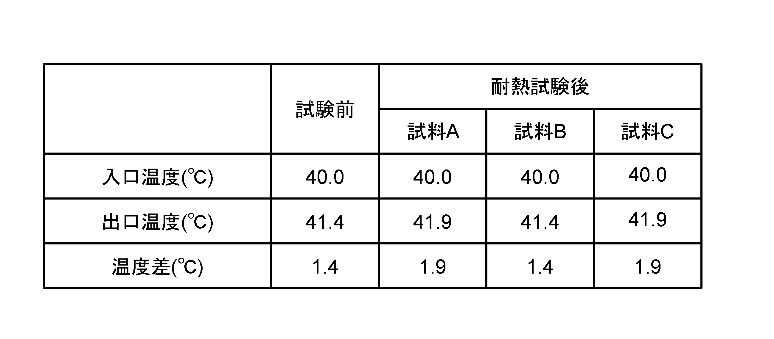
- the heat insulation performance of the heat insulation pipes 1 of Examples 1 to 6 was evaluated by the following method. First, as shown in FIG. 4, the heat insulating pipe 1 was arranged so that the heat insulating member 3 substantially entered the thermostat 23, and the temperature in the thermostat 23 was heated to 80 ° C. Next, the water stored in the water tank 25 was supplied to the joint 6a of the heat insulating pipe 1 at a flow rate of 24 mL / min by the pump 24, and the water discharged from the joint 6c was returned to the water tank 25 to circulate the water. Next, the heater 26 is set so that the temperature of the pipe 2 exposed to the outside (hereinafter referred to as the inlet temperature) can be maintained at about 40 ° C.
- the inlet temperature the temperature of the pipe 2 exposed to the outside
- the temperature of the pipe 2 exposed to the outside (hereinafter referred to as the outlet temperature) was measured at T 2 between the joint 6 c and the heat insulating member 3.
- the heat insulation performance of the heat insulation piping 1 was evaluated from the difference between the measured outlet temperature and the inlet temperature.
- the heat insulation piping 1 has high heat insulation performance, so that a temperature difference is small.
- the temperature difference of the comparative example 2 provided with the corrugated tube 21 is smaller than the comparative example 1. Therefore, it can be seen that the corrugated tube 21 also has a heat insulating effect. However, since the temperature difference of the comparative example 2 is larger than the temperature difference of the heat insulation piping of Example 1, it cannot be said that the heat insulation performance which the corrugated tube 21 has is sufficient.
- the heat insulating piping 1 of the second and third embodiments has a temperature difference similar to that of the first embodiment. I understand. Therefore, it can be seen that the heat insulation pipe 1 includes the corrugated tube 21, but a further heat insulation effect cannot be obtained, but a high heat insulation performance can be obtained by the heat insulation member 3.
- the heat insulation pipe 1 of Example 5 Comparing the heat insulation pipe 1 of Example 1 and the heat insulation pipe 1 of Example 5 which performed the heat treatment, the heat insulation pipe 1 of Example 5 has a smaller outer diameter, and the heat insulation member 3 contracts. I understand that. Moreover, the heat insulation piping 1 of Example 5 is a temperature difference comparable as the heat insulation piping 1 of Example 1, and even if the heat insulation member 3 shrink
- the heat insulation pipe 1 used for the heat resistance test is a resin tube (TEU-4-8x6) as the pipe 2 covered with an aeroflex (model number: M10010) in which a slit is formed as the heat insulation member 3, and a tether tape ( Model No .: 51026), and the protective member 9 was produced by winding heat-resistant Irax tape VZL in this order.
- Three heat insulating pipes 1 having the same configuration (sample A, sample B, and sample C) were produced, and the heat resistance of the three heat insulating pipes 1 was evaluated.
Landscapes
- Engineering & Computer Science (AREA)
- General Engineering & Computer Science (AREA)
- Mechanical Engineering (AREA)
- Chemical & Material Sciences (AREA)
- Chemical Kinetics & Catalysis (AREA)
- Combustion & Propulsion (AREA)
- Health & Medical Sciences (AREA)
- Toxicology (AREA)
- Thermal Insulation (AREA)
- Exhaust Gas After Treatment (AREA)
Abstract
Description
図1に示す断熱配管1は、内部を流体が流通可能な配管2と、配管2を覆うように配置された断熱部材3とを備える。断熱配管1は、配管2に沿うように配置され、内部を加熱された流体が流通可能な温水配管4をさらに備えている。配管2と温水配管4とは、柔軟性を有し、円筒形状をしている。配管2と温水配管4とを形成する素材は、内部を流通する液体に応じて選択される。配管2は流体としての尿素水が内部を流通でき、温水配管4は加熱された流体としての不凍液が流通できるように素材が選択されている。本実施形態の場合、配管2と温水配管4とは樹脂で形成されている。
図3に示すように、断熱配管1は例えば建設機械11のSCRシステム12に用いられる。建設機械11は、例えばショベルカー等の建設作業に用いられる機械である。建設機械11は、エンジン13、エンジン13から排出された排気ガスが流れる排気管14、熱を外部へ放出させるラジエーター15、及びラジエーター15を冷却する冷却ファン16が格納されたエンジンルーム17と、建設機械11を操縦する操縦者が乗り込むキャビン18とを備えている。SCRシステム12は、機体前方に設けられたキャビン18と機体後方に設けられたエンジンルーム17の間の空間に配置されている。
本発明は上記実施形態に限定されるものではなく、本発明の趣旨の範囲内で適宜変更することが可能である。例えば、配管2、断熱部材3、温水配管4、結束部材5、固定部材10、継手6a、6b、保護部材8、9については、材質や形状を適宜変更することが可能である。

2 配管
3 断熱部材
4 温水配管
5 結束部材
6a、6b、6c 継手
7 スリット
8、9 保護部材
10 固定部材
Claims (7)
- 内部を流体が流通可能な配管と、
前記配管を覆うように配置された断熱部材とを備え、
前記配管がSCR触媒を用いる排気ガス浄化装置に用いられ、
前記断熱部材が、独立気泡構造をしており、雰囲気との熱の交換による前記流体の温度上昇を抑制できることを特徴とする断熱配管。 - 前記断熱部材が柔軟性を有していることを特徴とする請求項1に記載の断熱配管。
- 前記断熱部材が長軸方向に沿ったスリットを備えていることを特徴とする請求項1又は2に記載の断熱配管。
- 前記断熱部材は前記スリットが閉じるように閉塞部材で固定されていることを特徴とする請求項3に記載の断熱配管。
- 前記配管が端部に少なくとも1つの継手を備えていることを特徴とする請求項1~4のいずれか1項に記載の断熱配管。
- 前記配管と接するように配置され、加熱された流体が流通可能な温水配管をさらに備えていることを特徴とする請求項1~5のいずれか1項に記載の断熱配管。
- 前記配管と前記温水配管とが結束部材によって固定されていることを特徴とする請求項6に記載の断熱配管。
Priority Applications (4)
| Application Number | Priority Date | Filing Date | Title |
|---|---|---|---|
| KR1020177011328A KR20170061151A (ko) | 2014-09-30 | 2015-09-14 | 단열 배관 |
| EP15847946.9A EP3203046A4 (en) | 2014-09-30 | 2015-09-14 | Heat-insulated pipe arrangement |
| CN201580049579.3A CN106715852A (zh) | 2014-09-30 | 2015-09-14 | 隔热管 |
| US15/515,133 US10428995B2 (en) | 2014-09-30 | 2015-09-14 | Heat-insulated pipe arrangement |
Applications Claiming Priority (2)
| Application Number | Priority Date | Filing Date | Title |
|---|---|---|---|
| JP2014200983A JP2016070189A (ja) | 2014-09-30 | 2014-09-30 | 断熱配管 |
| JP2014-200983 | 2014-09-30 |
Publications (1)
| Publication Number | Publication Date |
|---|---|
| WO2016052156A1 true WO2016052156A1 (ja) | 2016-04-07 |
Family
ID=55630198
Family Applications (1)
| Application Number | Title | Priority Date | Filing Date |
|---|---|---|---|
| PCT/JP2015/075994 Ceased WO2016052156A1 (ja) | 2014-09-30 | 2015-09-14 | 断熱配管 |
Country Status (6)
| Country | Link |
|---|---|
| US (1) | US10428995B2 (ja) |
| EP (1) | EP3203046A4 (ja) |
| JP (1) | JP2016070189A (ja) |
| KR (1) | KR20170061151A (ja) |
| CN (1) | CN106715852A (ja) |
| WO (1) | WO2016052156A1 (ja) |
Families Citing this family (4)
| Publication number | Priority date | Publication date | Assignee | Title |
|---|---|---|---|---|
| IT201800006074A1 (it) * | 2018-06-06 | 2019-12-06 | Condotto per un fluido da trasportare, in particolare in un veicolo a motore. | |
| CN112628461B (zh) * | 2020-12-21 | 2022-11-08 | 宁津美华工业有限公司 | 一种液体输送专用阀 |
| JP7583364B2 (ja) * | 2021-01-18 | 2024-11-14 | 住友金属鉱山株式会社 | 配管加温具および配管加温方法 |
| CN117089847B (zh) * | 2023-08-22 | 2025-06-20 | 华电电力科学研究院有限公司 | 一种尿素水解制氨设备防腐方法及尿素水解制氨设备 |
Citations (3)
| Publication number | Priority date | Publication date | Assignee | Title |
|---|---|---|---|---|
| JP2003194290A (ja) * | 2001-12-27 | 2003-07-09 | Inoac Corp | 曲管用断熱材および曲管用断熱材の製造方法 |
| JP2011241734A (ja) * | 2010-05-17 | 2011-12-01 | Isuzu Motors Ltd | 尿素水タンク構造 |
| JP2013076437A (ja) * | 2011-09-30 | 2013-04-25 | Mirai Ind Co Ltd | 被覆流体管 |
Family Cites Families (22)
| Publication number | Priority date | Publication date | Assignee | Title |
|---|---|---|---|---|
| US3557840A (en) * | 1968-05-09 | 1971-01-26 | Atlas Chem Ind | Cellular plastic foam insulation board structures |
| US3602636A (en) * | 1969-11-06 | 1971-08-31 | Reynolds Metals Co | Wrapped service entrance cable |
| US3633630A (en) * | 1970-03-17 | 1972-01-11 | Dow Chemical Co | Conduit insulation |
| US3853149A (en) * | 1970-05-14 | 1974-12-10 | Moore & Co Samuel | Composite tubing |
| US3757031A (en) * | 1972-05-02 | 1973-09-04 | Thomas & Betts Corp | The like selectively closable protective enclosure for electrical splices and |
| US4399319A (en) * | 1981-11-18 | 1983-08-16 | Bio-Energy Systems, Inc. | Thermally insulated composite flexible hose |
| US4713271A (en) * | 1982-06-30 | 1987-12-15 | Cosden Technology, Inc. | Foamed polymer tubing |
| JPH0246394A (ja) * | 1988-08-04 | 1990-02-15 | Furukawa Electric Co Ltd:The | 冷媒管の防火区画部における貫通配管構造 |
| US5421371A (en) * | 1993-04-19 | 1995-06-06 | Nmc Of North America, Inc. | Multi-layered bonded closure system for foam tubes or profiles |
| JP2593199Y2 (ja) * | 1993-06-28 | 1999-04-05 | 株式会社クボタ | 漏液検知線付き断熱管 |
| US5400602A (en) * | 1993-07-08 | 1995-03-28 | Cryomedical Sciences, Inc. | Cryogenic transport hose |
| EP0739470B1 (en) * | 1994-01-14 | 1998-03-18 | Rockwool International A/S | Method and apparatus for insulating |
| JP3391664B2 (ja) * | 1997-07-23 | 2003-03-31 | 早川ゴム株式会社 | 給水配管又は給湯配管の防音構造 |
| JP4457305B2 (ja) * | 2005-03-29 | 2010-04-28 | 日本ポリウレタン工業株式会社 | 硬質ポリウレタンスラブフォームの製造方法および配管用断熱材 |
| JP4836074B2 (ja) | 2006-01-30 | 2011-12-14 | 株式会社トヨックス | 流体保温多束ホース |
| DE102006017414A1 (de) | 2006-04-13 | 2007-10-18 | Contitech Techno-Chemie Gmbh | Beheizte Harnstoffleitung für Abgasnachbehandlungsanlagen von Brennkraftmaschinen |
| WO2009014516A1 (en) | 2007-07-24 | 2009-01-29 | Volvo Trucks North America | Apparatus for heating a fluid in an automotive vehicle |
| JP5185679B2 (ja) | 2008-04-01 | 2013-04-17 | ニッタ株式会社 | 液体移送用チューブ |
| US8261558B2 (en) * | 2009-06-25 | 2012-09-11 | Nomaco Inc. | Self-adjusting insulation, including insulation particularly suited for pipe or duct |
| JP5698543B2 (ja) * | 2011-01-14 | 2015-04-08 | 日立建機株式会社 | 建設機械の尿素水タンク構造 |
| US20140305534A1 (en) * | 2013-04-11 | 2014-10-16 | Aeroflex Usa | Insulation Jacket |
| US9157565B2 (en) * | 2013-10-25 | 2015-10-13 | The Dragon Group, LLC | Encapsulated insulation |
-
2014
- 2014-09-30 JP JP2014200983A patent/JP2016070189A/ja active Pending
-
2015
- 2015-09-14 EP EP15847946.9A patent/EP3203046A4/en not_active Withdrawn
- 2015-09-14 KR KR1020177011328A patent/KR20170061151A/ko not_active Ceased
- 2015-09-14 US US15/515,133 patent/US10428995B2/en not_active Expired - Fee Related
- 2015-09-14 CN CN201580049579.3A patent/CN106715852A/zh active Pending
- 2015-09-14 WO PCT/JP2015/075994 patent/WO2016052156A1/ja not_active Ceased
Patent Citations (3)
| Publication number | Priority date | Publication date | Assignee | Title |
|---|---|---|---|---|
| JP2003194290A (ja) * | 2001-12-27 | 2003-07-09 | Inoac Corp | 曲管用断熱材および曲管用断熱材の製造方法 |
| JP2011241734A (ja) * | 2010-05-17 | 2011-12-01 | Isuzu Motors Ltd | 尿素水タンク構造 |
| JP2013076437A (ja) * | 2011-09-30 | 2013-04-25 | Mirai Ind Co Ltd | 被覆流体管 |
Non-Patent Citations (1)
| Title |
|---|
| See also references of EP3203046A4 * |
Also Published As
| Publication number | Publication date |
|---|---|
| KR20170061151A (ko) | 2017-06-02 |
| CN106715852A (zh) | 2017-05-24 |
| EP3203046A4 (en) | 2018-03-07 |
| US20170241585A1 (en) | 2017-08-24 |
| EP3203046A1 (en) | 2017-08-09 |
| US10428995B2 (en) | 2019-10-01 |
| JP2016070189A (ja) | 2016-05-09 |
Similar Documents
| Publication | Publication Date | Title |
|---|---|---|
| US10018296B2 (en) | Connector | |
| WO2016052156A1 (ja) | 断熱配管 | |
| WO2015151707A1 (ja) | 昇温及び遮熱配管 | |
| JP5020878B2 (ja) | 排気ガス浄化用還元剤の解凍保温装置 | |
| CN104867583A (zh) | 电线的冷却装置 | |
| US20140069540A1 (en) | Wrappable sleeve with heating elements and methods of use and construction thereof | |
| US10358962B2 (en) | Unit for feeding a reducing solution from the tank to the exhaust duct of an engine | |
| JP2016070190A (ja) | 断熱配管 | |
| EP3306047A1 (en) | Waste heat recovery device | |
| US10113466B2 (en) | System for treating the exhaust gases for a vehicle equipped with internal combustion engine | |
| JP2014062515A (ja) | 尿素水配管用遮熱材 | |
| JP4324216B2 (ja) | エンジン排気ガス熱回収器ならびにそれを使用したエンジン駆動式ヒートポンプまたはコージェネレーション | |
| BR102014031388A2 (pt) | sistemas e métodos para refrigeração de um módulo de dosagem de fluido para escapamento de motores a diesel de um veículo agrícola | |
| US9920673B2 (en) | Tempered SCR-line and tempered SCR-line bundles | |
| KR20120119645A (ko) | 파이프 보호 시스템 | |
| JP6585385B2 (ja) | 建設機械 | |
| KR20190137907A (ko) | 라인 조립체 | |
| JP2016070654A (ja) | 特に自動車における内燃機関の排ガス冷却器に関して、冷却材を熱交換器に供給する装置 | |
| US20100186389A1 (en) | Reductant Insulating System | |
| JP2015016742A (ja) | ウォッシャー液加熱方法及びウォッシャー液加熱装置 | |
| JP2009264674A (ja) | 二重管の曲げ加工方法およびその方法で曲げた二重管並びにその二重管を用いた二重管式熱交換器 | |
| RU2015148979A (ru) | Система охлаждения выхлопных газов для двигателя внутреннего сгорани | |
| CN105745409B (zh) | 废气处理装置 | |
| CN106121781B (zh) | 具有集成热管的投放模块 | |
| KR20130120620A (ko) | 우레아 에스씨알 시스템의 튜브 가열구조 |
Legal Events
| Date | Code | Title | Description |
|---|---|---|---|
| 121 | Ep: the epo has been informed by wipo that ep was designated in this application |
Ref document number: 15847946 Country of ref document: EP Kind code of ref document: A1 |
|
| REEP | Request for entry into the european phase |
Ref document number: 2015847946 Country of ref document: EP |
|
| WWE | Wipo information: entry into national phase |
Ref document number: 15515133 Country of ref document: US Ref document number: 2015847946 Country of ref document: EP |
|
| NENP | Non-entry into the national phase |
Ref country code: DE |
|
| ENP | Entry into the national phase |
Ref document number: 20177011328 Country of ref document: KR Kind code of ref document: A |