WO2016052731A1 - エンジンの動弁装置 - Google Patents
エンジンの動弁装置 Download PDFInfo
- Publication number
- WO2016052731A1 WO2016052731A1 PCT/JP2015/078055 JP2015078055W WO2016052731A1 WO 2016052731 A1 WO2016052731 A1 WO 2016052731A1 JP 2015078055 W JP2015078055 W JP 2015078055W WO 2016052731 A1 WO2016052731 A1 WO 2016052731A1
- Authority
- WO
- WIPO (PCT)
- Prior art keywords
- rocker
- rocker shaft
- arm
- rocker arm
- piston
- Prior art date
- Legal status (The legal status is an assumption and is not a legal conclusion. Google has not performed a legal analysis and makes no representation as to the accuracy of the status listed.)
- Ceased
Links
Images






Classifications
-
- F—MECHANICAL ENGINEERING; LIGHTING; HEATING; WEAPONS; BLASTING
- F01—MACHINES OR ENGINES IN GENERAL; ENGINE PLANTS IN GENERAL; STEAM ENGINES
- F01L—CYCLICALLY OPERATING VALVES FOR MACHINES OR ENGINES
- F01L1/00—Valve-gear or valve arrangements, e.g. lift-valve gear
- F01L1/12—Transmitting gear between valve drive and valve
- F01L1/18—Rocking arms or levers
-
- F—MECHANICAL ENGINEERING; LIGHTING; HEATING; WEAPONS; BLASTING
- F01—MACHINES OR ENGINES IN GENERAL; ENGINE PLANTS IN GENERAL; STEAM ENGINES
- F01L—CYCLICALLY OPERATING VALVES FOR MACHINES OR ENGINES
- F01L1/00—Valve-gear or valve arrangements, e.g. lift-valve gear
- F01L1/02—Valve drive
- F01L1/04—Valve drive by means of cams, camshafts, cam discs, eccentrics or the like
- F01L1/047—Camshafts
- F01L1/053—Camshafts overhead type
-
- F—MECHANICAL ENGINEERING; LIGHTING; HEATING; WEAPONS; BLASTING
- F01—MACHINES OR ENGINES IN GENERAL; ENGINE PLANTS IN GENERAL; STEAM ENGINES
- F01L—CYCLICALLY OPERATING VALVES FOR MACHINES OR ENGINES
- F01L1/00—Valve-gear or valve arrangements, e.g. lift-valve gear
- F01L1/02—Valve drive
- F01L1/022—Chain drive
-
- F—MECHANICAL ENGINEERING; LIGHTING; HEATING; WEAPONS; BLASTING
- F01—MACHINES OR ENGINES IN GENERAL; ENGINE PLANTS IN GENERAL; STEAM ENGINES
- F01L—CYCLICALLY OPERATING VALVES FOR MACHINES OR ENGINES
- F01L1/00—Valve-gear or valve arrangements, e.g. lift-valve gear
- F01L1/26—Valve-gear or valve arrangements, e.g. lift-valve gear characterised by the provision of two or more valves operated simultaneously by same transmitting-gear; peculiar to machines or engines with more than two lift-valves per cylinder
- F01L1/267—Valve-gear or valve arrangements, e.g. lift-valve gear characterised by the provision of two or more valves operated simultaneously by same transmitting-gear; peculiar to machines or engines with more than two lift-valves per cylinder with means for varying the timing or the lift of the valves
-
- F—MECHANICAL ENGINEERING; LIGHTING; HEATING; WEAPONS; BLASTING
- F01—MACHINES OR ENGINES IN GENERAL; ENGINE PLANTS IN GENERAL; STEAM ENGINES
- F01L—CYCLICALLY OPERATING VALVES FOR MACHINES OR ENGINES
- F01L13/00—Modifications of valve-gear to facilitate reversing, braking, starting, changing compression ratio, or other specific operations
-
- F—MECHANICAL ENGINEERING; LIGHTING; HEATING; WEAPONS; BLASTING
- F01—MACHINES OR ENGINES IN GENERAL; ENGINE PLANTS IN GENERAL; STEAM ENGINES
- F01L—CYCLICALLY OPERATING VALVES FOR MACHINES OR ENGINES
- F01L13/00—Modifications of valve-gear to facilitate reversing, braking, starting, changing compression ratio, or other specific operations
- F01L13/0005—Deactivating valves
-
- F—MECHANICAL ENGINEERING; LIGHTING; HEATING; WEAPONS; BLASTING
- F01—MACHINES OR ENGINES IN GENERAL; ENGINE PLANTS IN GENERAL; STEAM ENGINES
- F01L—CYCLICALLY OPERATING VALVES FOR MACHINES OR ENGINES
- F01L1/00—Valve-gear or valve arrangements, e.g. lift-valve gear
- F01L1/02—Valve drive
- F01L1/04—Valve drive by means of cams, camshafts, cam discs, eccentrics or the like
- F01L1/047—Camshafts
- F01L2001/0476—Camshaft bearings
-
- F—MECHANICAL ENGINEERING; LIGHTING; HEATING; WEAPONS; BLASTING
- F01—MACHINES OR ENGINES IN GENERAL; ENGINE PLANTS IN GENERAL; STEAM ENGINES
- F01L—CYCLICALLY OPERATING VALVES FOR MACHINES OR ENGINES
- F01L1/00—Valve-gear or valve arrangements, e.g. lift-valve gear
- F01L1/12—Transmitting gear between valve drive and valve
- F01L1/18—Rocking arms or levers
- F01L2001/186—Split rocking arms, e.g. rocker arms having two articulated parts and means for varying the relative position of these parts or for selectively connecting the parts to move in unison
Definitions
- the present invention relates to an engine valve gear capable of switching between a form in which two types of rocker arms are connected to each other and a form in which the connection is released.
- Patent Document 1 As a conventional valve operating device for this type of engine, for example, there is one described in Patent Document 1.
- the valve gear disclosed in Patent Document 1 converts the rotation of a camshaft into a reciprocating motion by a rocker arm and drives two intake valves or exhaust valves.
- the camshaft has a high-speed cam and two low-speed cams located on both sides of the high-speed cam.
- the high speed cam is formed in a shape in which the valve lift amount is relatively larger than that of the low speed cam.
- the rocker arm is composed of two main arms provided for each intake valve or each exhaust valve, and a sub arm positioned between these main arms.
- the main arm has a slipper with which the low-speed cam of the camshaft contacts, and is supported on the rocker shaft so as to be swingable.
- the main arm is biased toward the low speed cam by a valve spring of an intake valve or an exhaust valve.
- the sub-arm has a slipper with which the camshaft for high speed cam comes into contact, and is swingably supported by the rocker shaft.
- the sub arm is biased toward the high speed cam by a dedicated return spring.
- the main arm and the sub arm are connected and integrated with each other by a hydraulic switching mechanism, or are disconnected and disconnected.
- the switching mechanism includes a switching pin movably provided in the pin hole of the sub arm, a plunger movably provided in the plunger holes of the two main arms, and a hydraulic circuit for supplying hydraulic pressure to these plungers.
- the switching pin and the two plungers are configured to be located on the same axis when the intake valve or the exhaust valve is closed.
- the hydraulic circuit has an oil passage for each plunger provided in the rocker shaft, and a communication passage for each main arm that communicates the oil passage with the inside of the plunger hole.
- the oil passages in the rocker shaft are formed in a state where they are aligned in the axial direction of the rocker shaft and partitioned by a partition wall in the rocker shaft.
- the main arm and sub arm are integrated when one plunger pushes the switching pin and the other plunger.
- one plunger is fitted in the pin hole of the sub arm and is positioned across the one main arm and the sub arm.
- the switching pin is fitted over the plunger hole of the other main arm so as to straddle between the sub arm and the other main arm.
- the switching pin is pushed back by the other plunger so that one plunger is located only in the main arm and the switching pin is located only in the sub arm. In this way, the sub arm and the main arm are separated and disconnected, so that the sub arm pushed by the high speed cam swings independently, and the main arm pushed by the low speed cam becomes the intake valve or the exhaust valve. Drive.
- the valve gear disclosed in Patent Document 1 has a problem that it is impossible to form an oil passage for supplying lubricating oil to a connection portion between the main arm and the sub arm and the rocker shaft. This is because an oil passage for supplying hydraulic pressure to the plunger occupies the rocker shaft. Such a problem can be solved by arranging an oil passage for oil pressure supply and an oil passage for lubrication side by side in the radial direction of the rocker shaft. However, when this configuration is adopted, the outer diameter of the rocker shaft is increased, and accordingly, the rocker arm is also enlarged. For this reason, such a configuration cannot be adopted.
- a valve operating apparatus for an engine includes a plurality of camshaft support portions provided in a cylinder head in a state of being aligned in the axial direction of a crankshaft, and the plurality of camshaft support portions.
- a camshaft that is rotatably supported and has a cam for driving an intake valve or an exhaust valve, and the camshaft support portion are formed separately from each other, and is positioned between the camshaft support portions.
- a rocker housing unit attached to the head, a rocker shaft supported at both ends by the rocker housing unit, a first rocker arm swingably supported by the rocker shaft, and swingable by the rocker shaft
- the first rocker arm is selectively supported by a switching pin that is supported and movable in the axial direction of the rocker shaft.
- a second rocker arm to be connected; a first piston for moving the switching pin in one of the axial directions; a second piston for moving the switching pin in the other of the axial directions;
- a hydraulic pressure supply unit configured to supply hydraulic pressure to the first piston and the second piston, and one of the first piston and the second piston includes the first rocker arm and the first piston.
- the rocker arm is provided in one of the two rocker arms, and the other piston is located in the rocker housing alone located on the opposite side of the axial direction with respect to the one piston.
- the hydraulic pressure supply section that supplies hydraulic pressure to the one piston is provided in the one rocker arm and the rocker shaft.
- a hydraulic pressure supply section that includes a first oil passage formed in the rocker housing single body supporting one end of the shaft and supplies hydraulic pressure to the other piston is a second oil passage formed in the rocker housing single body. The oil passage is included.
- the hydraulic pressure applied to one of the two pistons is supplied through the first oil passage including the inside of the rocker shaft.
- the hydraulic pressure applied to the other piston is supplied through a second oil passage provided in the rocker housing alone.
- the first oil passage can be formed by a path from one rocker arm to one rocker shaft through one end of the rocker shaft. For this reason, the oil passage for lubrication can be formed in other parts except the one end part of the rocker shaft. Therefore, according to the present invention, the oil passage for lubrication can be provided in the rocker shaft without increasing the outer diameter of the rocker shaft while adopting the configuration in which the oil passage for supplying hydraulic pressure is formed in the rocker shaft.
- a possible engine valve gear can be provided.
- FIG. 1 is a side view of a valve gear according to the present invention.
- FIG. 1 illustrates a cylinder head and a rocker housing partly broken.
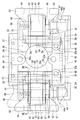
- FIG. 2 is a plan view of the cylinder head.
- FIG. 2 is drawn with the intake camshaft and exhaust camshaft removed.
- FIG. 3 is a side view for explaining a non-connected state (cylinder deactivation state).
- FIG. 4 is a plan view of the valve gear.
- FIG. 5 is a plan view of a single rocker housing. 6 is a cross-sectional view taken along line VI-VI in FIG. 7 is a cross-sectional view taken along line VII-VII in FIG. 8 is a cross-sectional view taken along line VIII-VIII in FIG.
- FIG. 9 is a cross-sectional view of a part of the rocker arm and the rocker housing.
- FIG. 10 is an exploded perspective view of the first rocker arm.
- FIG. 11 is a side view for explaining the connected state when the intake valve or the exhaust valve is closed.
- 12 is a cross-sectional view taken along line XII-XII of the second rocker arm and the first switching pin in FIG.
- FIG. 13 is a cross-sectional view for explaining a first step of the rocker arm manufacturing method.
- FIG. 14 is a cross-sectional view for explaining the second step and the third step of the rocker arm manufacturing method.
- FIG. 15 is a cross-sectional view for explaining a fourth step of the rocker arm manufacturing method.
- FIG. 10 is an exploded perspective view of the first rocker arm.
- FIG. 11 is a side view for explaining the connected state when the intake valve or the exhaust valve is closed.
- 12 is a cross-sectional view taken along line XII-X
- FIG. 16 is a plan view of a first rocker arm and a second rocker arm according to the second embodiment.
- FIG. 17 is a side view showing the main part of the valve gear according to the second embodiment.
- FIG. 18 is a cross-sectional view showing another embodiment of the rocker shaft.
- a valve operating apparatus 1 shown in FIG. 1 is installed in a DOHC type four-cylinder engine 2 mounted on a vehicle (not shown).
- the valve gear 1 includes a switching mechanism 3 (see FIG. 2) in order to switch a plurality of operation modes to be described later. Although the details will be described later, the switching mechanism 3 switches between a mode in which the cylinder is operated normally and a mode in which the cylinder is deactivated.
- the switching mechanism 3 shown in FIG. 2 is provided on the intake valve side (right side in FIG. 2) and exhaust valve side (left side in FIG. 2) of all cylinders.
- the operation mode switched by the switching mechanism 3 is an all-cylinder operation mode in which four cylinders are operated normally, and a partial cylinder operation mode in which only an arbitrary cylinder among the four cylinders is operated.
- FIG. 2 is drawn in a state where the switching mechanisms 3 are provided in all the cylinders so that the number of cylinders to be operated can be changed when the partial cylinder operation mode is adopted.
- the one-cylinder operation mode is set.
- the 1 ⁇ 2 reduction cylinder operation mode is set.
- a three-cylinder operation mode is set.
- four cylinders are deactivated, all cylinders are deactivated.
- the 1/2 reduction cylinder operation mode can be realized in the first operation mode and the second operation mode in which the operated cylinders are different.
- the first operation mode is an operation mode in which a cylinder (first cylinder) located at one end in the direction in which the four cylinders are arranged and a fourth cylinder (fourth cylinder) counted from one end are operated.
- the second operation mode is an operation mode in which the second cylinder (second cylinder) and the third cylinder (third cylinder) are operated from one end in the direction in which the four cylinders are arranged.
- the switching mechanism 3 is not illustrated in the case of only switching between the 1 / 2-cylinder operation mode and the all-cylinder operation mode, the switching mechanism 3 is usually provided only in the cylinder that is deactivated.
- the 1/2 reduction cylinder operation mode according to the first operation mode and the 1/2 reduction cylinder operation mode according to the second operation mode are based on predetermined rules. It can be switched alternately. For example, since the first operation mode and the second operation mode are switched at predetermined time intervals so that all the cylinders are operated substantially evenly, the 1/2 reduction cylinder operation mode is adopted. Nevertheless, the engine temperature distribution is even.
- the all cylinder deactivation mode is switched, for example, when the accelerator is off. When the all cylinder deactivation mode is adopted, the pumping loss can be reduced because the intake and exhaust of the combustion chamber are prevented from entering and exiting the cylinder only by repeating adiabatic compression and adiabatic expansion in each cylinder.
- the switching mechanism 3 constitutes a part of the valve gear 1 as shown in FIG.
- the valve gear 1 converts the rotations of the intake camshaft 5 and the exhaust camshaft 6 provided in the cylinder head 4 into reciprocating motions by the rocker arm 7, respectively.
- the exhaust valve 9 is driven.
- the portion for driving the intake valve 8 and the portion for driving the exhaust valve 9 in the valve operating device 1 have the same structure. Therefore, in the following, members having the same configuration on the intake valve 8 side and the exhaust valve 9 side will be described on the exhaust valve 9 side, and the members on the intake valve 8 side will be assigned the same reference numerals. The description is omitted.
- the intake camshaft 5 and the exhaust camshaft 6 are each provided with a camshaft body 11 rotatably supported by the cylinder head 4 and a cam 12 provided on the camshaft body 11.
- the intake camshaft 5 and the exhaust camshaft 6 are collectively referred to simply as a camshaft 14.
- the camshaft body 11 is formed in a rod shape with a circular cross section.
- the cam 12 includes a base circle portion 12a and a nose portion 12b.
- the base circle portion 12a has a shape that becomes a part of a cylinder located on the same axis as the camshaft body 11, and is formed in such a size that the valve lift amount of the intake valve 8 or the exhaust valve 9 becomes zero.
- the nose portion 12b is formed in a shape that protrudes from the base circle portion 12a outward in the radial direction by a predetermined protrusion amount in a cross-sectional mountain shape.
- Two intake valves 8 and two exhaust valves 9 are provided for each cylinder, and are supported by the cylinder head 4 so as to be reciprocally movable.
- the two intake valves 8, 8 are arranged at a predetermined interval in the axial direction of the intake camshaft 5.
- the two exhaust valves 9 and 9 are arranged at a predetermined interval in the axial direction of the exhaust camshaft 6.
- the intake valve 8 includes a valve body 8 a that opens and closes an intake port 15 of the cylinder head 4, and a valve shaft 8 b that extends from the valve body 8 a into the valve operating chamber 16 of the cylinder head 4.
- the exhaust valve 9 includes a valve body 9 a that opens and closes the exhaust port 17 of the cylinder head 4 and a valve shaft 9 b that extends from the valve body 9 a into the valve operating chamber 16 of the cylinder head 4.
- the valve shafts 8 b and 9 b are supported via valve shaft guides 8 c and 9 c that are press-fitted into the valve chamber bottom wall 16 a of the cylinder head 4.
- a valve spring 18 that urges the intake valve 8 and the exhaust valve 9 in a closing direction is provided between the distal ends of the valve shafts 8b and 9b and the bottom surface 16b of the valve chamber bottom wall 16a.
- cap-shaped shims 19 are respectively provided at the distal ends of the valve shafts 8b and 9b.
- the upstream end of the intake port 15 opens to one side of the cylinder head 4.
- the downstream end of the intake port 15 opens to the combustion chamber 20 for each cylinder.
- the upstream end of the exhaust port 17 opens to the combustion chamber 20.
- the downstream end of the exhaust port 17 opens to the other side of the cylinder head 4.
- a cylindrical wall portion 21 for attaching and detaching a spark plug (not shown) from above is provided at a portion corresponding to the central portion of the combustion chamber 20 in the cylinder head 4.
- the valve operating chamber 16 of the cylinder head 4 is formed by being surrounded by the cylinder head 4 and a cylinder head cover 4a (see FIG. 1) attached to the cylinder head 4, and a partition wall 22 (see FIG. 1) located between the cylinders. 2) for each cylinder.
- a cylinder head cover 4a (see FIG. 1) attached to the cylinder head 4, and a partition wall 22 (see FIG. 1) located between the cylinders. 2) for each cylinder.
- an intake side journal portion 23 for supporting the intake camshaft 5 and an exhaust side journal portion 24 for supporting the exhaust camshaft 6 are formed at the upper end of the partition wall 22.
- a cam cap 25 is attached to these journal portions 23 and 24 by a plurality of mounting bolts 26 (see FIG. 2).
- the cam cap 25 rotatably supports the intake camshaft 5 and the exhaust camshaft 6 with the journal portions 23 and 24 interposed therebetween.
- the camshaft support portion 27 including the journal portions 23 and 24 and the cam cap 25 is provided on the partition wall 22 between the cylinders described above and the partition walls 28 and 29 at the front end portion and the rear end portion of the cylinder head 4.
- the front end portion and the rear end portion referred to here are an upper end portion and a lower end portion in FIG. 2, and are one end portion and the other end portion in the axial direction of the crankshaft (not shown) of the engine 2.
- a rocker housing unit 31 for supporting a rocker arm 7 to be described later is provided between the camshaft support portions 27 in the cylinder head 4.
- the rocker housing unit 31 according to this embodiment is provided for each cylinder, and is fixed to a support wall portion 32 (see FIG. 1) integrally formed with the cylinder head 4 across the partition wall 22 by fixing bolts 33. ing.
- the support wall portion 32 extends in the axial direction of the crankshaft so as to intersect the cylinder wall portion 21 for attaching and detaching the spark plug.
- the upper end of the cylindrical wall 21 is connected to the support wall 32, and the support wall 32 is formed with a circular opening (not shown) connected to the inside of the cylindrical wall 21.
- the valve chamber bottom wall 16a, the cylinder wall portion 21, the partition wall 22, and the support wall portion 32 all constitute a part of the cylinder head 4 and are integrally formed when the cylinder head 4 is cast.
- the rocker housing unit 31 includes three functional units as shown in FIGS. 4 and 5. These functional parts are the first rocker shaft support part 34 located at the uppermost position in FIG. 5, the second rocker shaft support part 35 located at the lowest position in FIG. 5, and these first and second rocker shaft support parts 35. This is a connecting portion 36 that connects the rocker shaft support portions 34 and 35 together.
- the first and second rocker shaft support portions 34 and 35 and the connecting portion 36 according to this embodiment are integrally formed by casting.
- the first rocker shaft support portion 34 and the second rocker shaft support portion 35 are formed with two circular holes 38 and 39 into which the rocker shaft 37 (see FIG. 4) is fitted, and fixing bolts.
- a through hole 33a (see FIG. 5) for passing 33 is formed.
- one of the circular holes 38 and 39 is fitted with a rocker shaft 37 that supports the rocker arm 7 for driving the intake valve.
- the other circular holes 38 and 39 are fitted with a rocker shaft 37 that supports the rocker arm 7 for driving the exhaust valve.
- the first rocker shaft support portion 34 has a base portion 34a attached to the support wall portion 32 and a convex portion 34b protruding upward from the base portion 34a.
- Two circular holes 38 into which one end of the rocker shaft 37 is fitted are formed in the convex portion 34b.
- the two circular holes 38 of the first rocker shaft support portion 34 are through holes.
- One end of the rocker shaft 37 is fitted in the circular hole 38.
- a first oil hole 40 is connected to the circular hole 38.
- the first oil hole 40 is V-shaped when viewed from the axial direction of the rocker shaft 37 in order to guide oil from the first oil inlet / outlet 41 of the cylinder head 4 to the two circular holes 38. It is formed in a shape.
- the circular hole 38 and the first oil hole 40 constitute a part of a first hydraulic pressure supply unit 42 (see FIG. 9) described later.
- the first hydraulic pressure supply unit 42 corresponds to the “hydraulic pressure supply unit that supplies hydraulic pressure to one piston” in the present invention.
- the first oil inlet / outlet port 41 is configured using the support wall portion 32 of the cylinder head 4.
- the second rocker shaft support portion 35 has a hydraulic operation portion 35a attached to the support wall portion 32, and a convex portion 35b protruding upward from the hydraulic operation portion 35a. ing.
- the hydraulic operation part 35a is formed in a shape that protrudes on both sides from the convex part 35b.
- Cylinder holes 43 are formed in both end portions of the hydraulic operation portion 35a. These cylinder holes 43 are non-through holes extending in parallel with the axis of the camshaft 14 and open toward one side where the first rocker shaft support portion 34 is located. These cylinder holes 43 are movably fitted with hydraulic pistons 44 (see FIG. 9) that constitute a part of the switching mechanism 3 described above.
- the hydraulic piston 44 corresponds to “the other piston” in the present invention.
- the second oil hole 45 is connected to the cylinder hole 43.
- the second oil hole 45 includes a cylinder hole 43 on the intake valve side located on one end side of the hydraulic operating portion 35 a and a cylinder hole 43 on the exhaust valve side located on the other end side.
- the oil inlet / outlet 46 is connected.
- the second oil inlet / outlet 46 is configured using the support wall portion 32.
- the second oil hole 45 constitutes a “second oil passage” in the present invention.
- the hydraulic piston 44 operates when hydraulic pressure is supplied via the second hydraulic pressure supply portion 47 including the second oil hole 45 and the cylinder hole 43.
- the second hydraulic pressure supply unit 47 corresponds to the “hydraulic pressure supply unit that supplies hydraulic pressure to the other piston” in the present invention.
- the hydraulic piston 44 has a pressing plate 44 a that protrudes from the cylinder hole 43.
- the pressing plate 44a is formed larger than the cylinder hole 43 in a direction perpendicular to the camshaft axis.
- two circular holes 39 into which the other end of the rocker shaft 37 is fitted are formed in the convex portion 35 b of the second rocker shaft support portion 35.
- the circular hole 39 is a non-through hole.
- the rocker shaft 37 is engaged with a stopper pin 48 press-fitted into the convex portion 35b from above, and is prevented from coming off and rotating.
- a third oil hole 49 is connected to the two circular holes 39.
- the third oil hole 49 connects the two circular holes 39, 39 to the lubricating oil supply unit 50 of the cylinder head 4.
- the lubricating oil supply unit is configured using the support wall 32.
- an oil hole 51 formed of a non-through hole that opens at one end of the rocker shaft 37 (one end supported by the second rocker shaft support portion 35) is formed in the shaft center portion of the rocker shaft 37.
- two oil passages 53 and 54 are formed that are adjacent to each other in the axial direction of the rocker shaft 37 with the partition portion 52 interposed therebetween.
- These oil passages 53 and 54 are defined by a single oil hole 51 formed in the rocker shaft 37 and a plug member 55 constituting the partition portion 52 described above.
- the oil hole 51 includes a large diameter part 51 a including an open end and a small diameter part 51 b located on the other end side from the plug member 55.
- the plug member 55 closes the boundary portion between the large diameter portion 51a and the small diameter portion 51b.
- one oil passage 53 formed by the small diameter portion 51 b is a first oil hole 40 formed in the first rocker shaft support portion 34. It is connected to the.
- the oil passage 53 constitutes a part of the first hydraulic pressure supply unit 42.
- the other oil passage 54 formed by the large diameter portion 51a is for supplying oil to a lubricated portion of the rocker arm 7 described later.
- First to third communication holes 56 to 58 that connect the inside of the large diameter portion 51 a of the oil hole 51 and the outside of the rocker shaft 37 are formed at three locations in the middle portion of the rocker shaft 37.
- the oil sent from the lubricating oil supply section 50 through the third oil hole 49 and into the circular hole 39 passes through the oil hole 51 in the rocker shaft 37 and the first to third communication holes 56 to 58 to the outside of the rocker shaft 37.
- the connecting portion 36 of the rocker housing unit 31 is formed in a plate shape extending in the axial direction of the camshaft 14. As shown in FIG. 5, a circular hole 36a is formed through the connecting portion 36 so as to be concentrically connected to the circular opening (not shown) of the support wall portion 32 described above.
- the rocker arm 7 is formed of a plurality of members as shown in FIGS.
- the plurality of members include a first rocker arm 62, a second rocker arm 64, first to third switching pins 65 to 67, and the like.
- the first rocker arm 62 has a roller 61 that contacts the cam 12.
- a valve pressing portion 63 that presses the intake valve 8 or the exhaust valve 9 is provided at the swinging end portion of the second rocker arm 64.
- the first to third switching pins 65 to 67 are for selectively connecting the first rocker arm 62 and the second rocker arm 64.
- the first rocker arm 62 includes a first arm piece 62a and a second arm piece 62b that are swingably supported by the rocker shaft 37, and these first and second arms.
- the two connecting pieces 62c and 62d that connect the pieces 62a and 62b are formed in a U-shape when viewed from the front.
- the rocker shaft 37 is slidably fitted in a through hole 68 formed in the first arm piece 62a and the second arm piece 62b.
- FIG. 10 One end of the first arm piece 62a and the second arm piece 62b that are supported by the rocker shaft 37 and directed to the camshaft 14 when viewed from the axial direction of the rocker shaft 37 are shown in FIG. As shown in FIG. 10, a protrusion 69 is provided.
- a roller 61 is inserted between the first arm piece 62a and the second arm piece 62b.
- the roller 61 constitutes a cam follower including a rotating body that contacts the cam 12.
- the roller 61 is rotatably supported by a support shaft 72 fitted in the shaft holes 71 of the first arm piece 62a and the second arm piece 62b via a needle bearing (not shown).
- the axis of the support shaft 72 is parallel to the axis of the rocker shaft 37.
- a part of the outer peripheral surface of the roller 61 faces the rocker shaft 37 as shown in FIG.
- a space S ⁇ b> 1 is formed between the roller 61 and the rocker shaft 37.
- a portion of the rocker shaft 37 facing the roller 61 is provided with a second communication hole 57 located at the center of the first to third communication holes 56 to 58 described above.
- a part of the oil sent into the rocker shaft 37 is ejected from the second communication hole 57 located at the center and adheres to the outer peripheral surface of the roller 61, and a contact portion between the roller 61 and the cam 12 is formed.
- Lubricate located on both sides of the three communication holes 56 to 58 are provided in a portion of the rocker shaft 37 that passes through the second rocker arm 64. Therefore, the portion to be lubricated in contact with the rocker shaft 37 in the second rocker arm 64 is lubricated by the oil flowing out from the first and third communication holes 56 and 58.
- a first pin hole 73 including a through hole is formed in the shaft center portion of the support shaft 72.
- a first switching pin 65 is fitted in the first pin hole 73 so as to be movable in the axial direction of the rocker shaft 37.
- the first switching pin 65 is formed in a cylindrical shape.
- the first switching pin 65 is formed longer than the width of the first rocker arm 62 (the length of the first rocker arm 62 in the axial direction of the rocker shaft 37) by a predetermined length.
- a convex portion 74 protruding from the first rocker arm 62 in the first switching pin 65 is accommodated in a concave portion 75 of a second rocker arm 64 described later.
- a return spring member 76 is provided between the connecting piece 62 d of the first rocker arm 62 and the cylinder head 4.
- the spring member 76 has a first rocker arm in a direction in which the roller 61 is pressed against the cam 12, in other words, a return direction that is opposite to a direction in which the first rocker arm 62 is swung by the cam 12. 62 is energized. For this reason, the first rocker arm 62 swings against the spring force of the spring member 76 by being pushed by the cam 12.
- the second rocker arm 64 includes a first arm half 81 and a second arm half 82 that are swingably supported by the rocker shaft 37, and these arm halfs. It has the 1st connection part 83 and the 2nd connection part 84 which connect the parts 81 and 82.
- the first and second arm half portions 81 and 82 and the first and second connecting portions 83 and 84 according to this embodiment are integrally formed by integral molding.
- the rocker shaft 37 is slidably fitted in a through hole 85 formed in the first arm half 81 and the second arm half 82.
- a second pin hole 91 made of a non-through hole and an oil hole 92 extending from the pin hole 91 toward the rocker shaft 37 are formed in the intermediate portion of the first arm half 81. Is formed.
- the second pin hole 91 constitutes a cylinder hole.
- One end of the oil hole 92 opens into the second pin hole 91, and the other end is connected to the fourth communication hole 93 of the rocker shaft 37.
- the fourth communication hole 93 extends in the radial direction of the rocker shaft 37 and connects the inside of the small diameter portion 51 b of the oil hole 51 and the oil hole 92.
- the second pin hole 91 is connected via the first oil passage 94 including the oil hole 92, the fourth communication hole 93, the small diameter part 51 b of the oil hole 51, and the first oil hole 40.
- the cylinder head 4 communicates with a first oil inlet / outlet 41.
- a third pin hole 95 made of a through hole is formed in an intermediate portion of the second arm half 82.
- a circlip 96 is provided at one end of the third pin hole 95 (the end located on the side opposite to the first arm half 81).
- the first arm half portion 81 and the second arm half portion 82 are disposed at positions sandwiching the first rocker arm 62 from both sides in the axial direction while being supported by the rocker shaft 37 so as to be swingable. .
- a projection 86 is provided at a portion that is an intermediate portion of the second arm half 82 and that faces the camshaft 14.
- a disk portion 87 is provided at a portion of the camshaft 14 facing the protrusion 86 as shown by a two-dot chain line in FIG.
- the disk portion 87 is formed in a disk shape having the same diameter as the base circle portion 12 a of the cam 12, and is provided at a position adjacent to the cam 12. As shown in FIG.
- a gap d ⁇ b> 1 is formed between the disk portion 87 and the protrusion 86 when the valve pressing portion 63 of the second rocker arm 64 is in contact with the shim 19.
- the protrusion 86 hits the disk portion 87 when the second rocker arm 64 bounces and swings toward the camshaft 14 due to vibration or the like, and restricts further swinging of the second rocker arm 64.
- the protrusion 86 is interposed between the disk portion 87 of the cam shaft 14 and a slight gap d ⁇ b> 2 in a state where the roller 61 of the first rocker arm 62 is in contact with the base circle portion 12 a of the cam 12. Are close to each other.
- This gap d2 is narrower than the gap d1 shown in FIG.
- a valve clearance d ⁇ b> 3 is formed between the valve pressing portion 63 of the second rocker arm 64 and the shim 19.
- the swing end portions of the first arm half 81 and the second arm half 82 are connected to each other by a first connecting portion 83.
- valve pressing portions 63 that press the shims 19 of the intake valve 8 or the exhaust valve 9 are provided. That is, the second rocker arm 64 pushes the two intake valves 8 or exhaust valves 9 simultaneously per cylinder.
- the base portions supported by the rocker shaft 37 in the first arm half portion 81 and the second arm half portion 82 are connected to each other by a second connecting portion 84.
- the second connecting portion 84 is disposed at one end of the first arm half 81 and the second arm half 82 supported by the rocker shaft 37, and is connected to the camshaft. 14 and 14 are connected to each other. Moreover, the 2nd connection part 84 crosses the 1st rocker arm 62 in planar view, as shown in FIG. For this reason, the first rocker arm 62 swings toward the cam 12 with respect to the second rocker arm 64, whereby the protrusion 69 of the first rocker arm 62 approaches the second connecting portion 84.
- a stopper 88 (see FIG. 3) that comes into contact with the protrusion 69 of the first rocker arm 62 is provided on the lower surface (surface opposite to the cam 12) of the second connecting portion 84. .
- the protrusion 69 contacts the stopper 88 when the first rocker arm 62 is swung by the spring force of the spring member 76 in a state where the intake valve 8 or the exhaust valve 9 is closed.
- the protrusion 69 comes into contact with the stopper 88, the first rocker arm 62 and the second rocker arm 64 are integrally biased in the return direction by the spring force of the spring member 76 thereafter.
- the first to third pin holes 73, 91, and 95 are kept aligned on the same axis. Accordingly, the first to third switching pins 65 to 67 can be easily and reliably switched to the connected state shown in FIG. In this connected state, the first switching pin 65 moves to a position straddling the first pin hole 73 and the third pin hole 95, and the second switching pin 66 moves to the first pin hole 73. And the second pin hole 91.
- the stopper 88 is positioned in the concave space S2 below the cam 12 at the stopper contact position of the first rocker arm 62 where the protrusion 69 of the first rocker arm 62 contacts the stopper 88. is doing.
- the concave space S ⁇ b> 2 is a space surrounded by the cam 12 of the camshaft 14, the roller 61 of the first rocker arm 62, and the rocker shaft 37 when viewed from the axial direction of the rocker shaft 37.
- a state in which the protrusion 69 of the first rocker arm 62 contacts the stopper 88 is simply referred to as a “stopper contact state”.
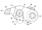
- a concave portion 75 for accommodating the convex portion 74 of the first switching pin 65 is formed on the inner side surface of the first arm half portion 81 facing the first rocker arm 62 as shown in FIG. Yes.
- the second pin hole 91 opens into the recess 75.
- a concave portion 75 is formed on the inner side surface of the second arm half 82 that faces the first rocker arm 62, as is the case with the first arm half 81, although not shown.
- the third pin hole 95 opens into the recess 75.
- the recess 75 of the first arm half 81 and the recess 75 of the second arm half 82 are formed in the same shape at the same position when viewed from the axial direction of the rocker shaft 37.
- the concave portion 75 is formed in a groove shape extending downward from the second pin hole 91 or the third pin hole 95, and has a plurality of functional portions.
- the downward direction is a direction in which the second rocker arm 64 swings when the intake valve 8 or the exhaust valve 9 is pushed open.
- the plurality of functional portions include a non-regulating portion 75a through which the convex portions 74 at both ends of the first switching pin 65 pass when the first rocker arm 62 swings with respect to the second rocker arm 64, and the convex portion 74 is a regulating portion 75b that regulates the movement of 74.
- the non-regulating portion 75a is configured such that the first rocker arm 62 swings relative to the second rocker arm 64 and the maximum swing position without restricting the passage of the protrusion 74 in a state where a predetermined condition is satisfied. It is formed in the shape which permits rocking
- the state in which the predetermined condition is satisfied is a state in which the first rocker arm 62 is supported by the rocker shaft 37 and is capable of swinging with respect to the second rocker arm 64 (not described later) State).
- the swing start position is the position of the first rocker arm 62 when the roller 61 is in contact with the base circle portion 12a of the cam 12.
- the maximum swinging position is the position of the first rocker arm 62 when the portion of the nose portion 12b where the protrusion amount is maximum is in contact with the roller 61.
- the restricting portion 75b restricts the passage of the convex portion 74 so that the first rocker arm 62 exceeds the maximum rocking position with respect to the second rocker arm 64. Regulate swinging. That is, the restricting portion 75b is formed in a shape that intersects the movement locus of the convex portion 74 when the first rocker arm 62 swings beyond the maximum swing position, as indicated by a two-dot chain line in FIG. Has been.
- the restricting portion 75b is formed in the opening 97 located on one end side of the recess 75 having a groove shape.
- the opening 97 opens toward the lower side of the second rocker arm 64 (in the direction opposite to the camshaft 14).
- the restricting portion 75 b is formed so that the opening width of the opening 97 is larger than the outer diameter of the convex portion 74.
- the convex portion 74 can enter and exit the concave portion 75 through the opening 97 in a state where the first rocker arm 62 is not supported by the rocker shaft 37. That is, the restricting portion 75 b is formed in a shape that allows the convex portion 74 to pass in a state where the first rocker arm 62 is not supported by the rocker shaft 37.
- the second pin hole 91 and the third pin hole 95 of the second rocker arm 64 cross the first arm half 81 and the second arm half 82 so as to cross the rocker shaft. 37 extends parallel to the axis.
- the distance between the center line of the second pin hole 91 and the third pin hole 95 and the axis of the rocker shaft 37 is such that the center line of the first pin hole 73 of the first rocker arm 62 and the rocker shaft 37. It is consistent with the distance between the axis.
- the first to third pin holes 73, 91, 95 are formed at positions equidistant from the rocker shaft 37 in the first rocker arm 62 and the second rocker arm 64.
- the first pin hole 73, the second pin hole 91, and the third pin hole 95 have a swing angle of the first rocker arm 62 and a swing angle of the second rocker arm 64 in advance. It is positioned on the same axis in a state where a predetermined angle is obtained.
- the predetermined angle is an angle when the intake valve 8 or the exhaust valve 9 is closed (when the valve lift amount becomes 0), and is an angle when the above-described stopper is in contact.
- the hole diameters of the second pin hole 91 and the third pin hole 95 coincide with the hole diameter of the first pin hole 73.
- a second switching pin 66 is movably fitted in the second pin hole 91, and the second switching pin 66 faces the first rocker arm 62.
- An urging spring member 98 is provided.
- the second switching pin 66 constitutes a hydraulic piston formed in a bottomed cylindrical shape, and in the second pin hole 91 constituting the cylinder hole in a state where the bottom portion faces the first switching pin 65. Has been inserted.
- the second switching pin 66 constitutes “one piston of the first piston and the second piston” in the present invention.
- the valve operating apparatus 1 includes a first arm half portion 81 of the second rocker arm 64, one end portion of the rocker shaft 37, the first rocker shaft support portion 34, and the first rocker shaft described above.
- a first hydraulic pressure supply unit 42 including an oil passage 94 and the like is provided.
- the first hydraulic pressure supply section 42 corresponds to the “hydraulic pressure supply section that supplies hydraulic pressure to one piston” in the present invention, and supplies hydraulic pressure to the second switching pin 66.
- the length of the second switching pin 66 is a length that can be accommodated in the second pin hole 91 as shown by a two-dot chain line in FIG.
- the spring member 98 is provided between the inner bottom portion of the second switching pin 66 and the bottom portion of the second pin hole 91.
- the second switching pin 66 is pushed by the hydraulic pressure applied through the first oil passage 94 and the spring force of the spring member 98, whereby the first to third pin holes 73, 91, 95 are opened.
- the stopper contact state located on the same axis one end of the first switching pin 65 is pushed to the other end.
- a third switching pin 67 is movably fitted in the third pin hole 95.
- the third switching pin 67 and the first switching pin 65 and the second switching pin 66 described above constitute a “switching pin” in the present invention.
- the third switching pin 67 has a large-diameter portion 67a facing the first switching pin 65, and a small-diameter portion 67b protruding from the large-diameter portion 67a toward the outside of the second rocker arm 64. Yes.
- a step 99 is formed at the boundary between the large diameter portion 67a and the small diameter portion 67b.
- the outer diameter of the small diameter portion 67 b is smaller than the inner diameter of the circlip 96 provided in the third pin hole 95.
- the distal end surface of the small diameter portion 67b faces the pressing plate 44a of the hydraulic piston 44 described above.
- the length of the third switching pin 67 in the axial direction is slightly shorter than the length of the third pin hole 95 as shown by a two-dot chain line in FIG. For this reason, even if the hydraulic piston 44 moves forward until it hits the second arm half 82, the entire third switching pin 67 is accommodated in the second arm half 82, and the first switching pin 65 Both ends protrude from the first rocker arm 62 substantially evenly.
- the first to third switching pins 65 to 67 are configured so that the hydraulic pressure in the first oil passage 94 rises when the stopper is in contact with the hydraulic piston 44 and the hydraulic piston 44 is not in operation. It is pushed to the hydraulic piston 44 side by the spring force of 98 and moves to the connecting position shown by the solid line in FIG.
- the non-operating state of the hydraulic piston 44 is a state where no hydraulic pressure is applied to the hydraulic piston 44.
- the connection position is a position where the movement of the third switching pin 67 is restricted when the step 99 abuts the circlip 96. In this state, the first switching pin 65 is located across the first rocker arm 62 and the second arm half portion 82 of the second rocker arm 64.
- the second switching pin 66 is located across the first rocker arm 62 and the first arm half 81 of the second rocker arm 64. As described above, the first to third switching pins 65 to 67 are positioned at the coupling positions, whereby the first rocker arm 62 and the second rocker arm 64 are coupled to each other, and the rocker shaft 37 is the center. Can be swung.
- the rotation of the cam 12 is converted into a reciprocating motion by the first rocker arm 62 and the second rocker arm 64, and the intake valve 8 or the exhaust valve 9 is driven.
- the third switching pin 67 is pressed against the circlip 96 and held at the coupling position.
- the third switching pin 67 moves as the second rocker arm 64 swings in a state in which a clearance is formed between the hydraulic piston 44 and the pressing plate 44a. Even if the first and second rocker arms 62 and 64 swing as described above, a part of the pressing plate 44a is always formed to have a size facing the third switching pin 67.
- the hydraulic piston 44 retreats to a position that does not prevent the first to third switching pins 65 to 67 from moving to the coupling position when in the non-operating state.
- the hydraulic pressure in the first oil passage 94 disappears, the hydraulic pressure in the second oil hole 45 rises, and when the hydraulic piston 44 changes from the inoperative state to the activated state, the first to third switching pins 65 ⁇ 67 are pushed by the hydraulic piston 44 and moved to the unconnected position indicated by a two-dot chain line in FIG. 9.
- the pressing plate 44 a of the hydraulic piston 44 contacts the second arm half 82.
- the third switching pin 67 is accommodated in the third pin hole 95. Both ends of the first switching pin 65 slightly protrude from the first rocker arm 62 and enter the recess 75 of the first and second arm halves 81 and 82.
- the second switching pin 66 is accommodated in the second pin hole 91.
- the first to third switching pins 65 to 67 are located at the non-connection positions, the connection state between the first rocker arm 62 and the second rocker arm 64 is released.
- the first rocker arm 62 and the second rocker arm 64 can swing individually, the first rocker arm 62 is pushed by the cam 12 and swings as shown in FIG. Only the second rocker arm 64 does not swing.
- the intake valve 8 or the exhaust valve 9 is kept closed, the cylinder is deactivated.
- the outer diameters of the first to third switching pins 65 to 67 according to this embodiment are such that even if the first rocker arm 62 swings with respect to the second rocker arm 64 as shown in FIG. When viewed from the axial direction, the portions are always set so as to face each other.
- the cylindrical jig 101 is fitted in the shaft hole 71 of the first rocker arm 62 instead of the support shaft 72.
- the outer diameter of the cylindrical jig 101 is an outer diameter that fits into the shaft hole 71 of the first rocker arm 62.
- the inner diameter of the cylindrical jig 101 coincides with the inner diameters of the second pin hole 91 and the third pin hole 95 of the second rocker arm 64.
- the first to second pin holes 91 and 95 of the second rocker arm 64 and the hollow portion 101a of the cylindrical jig 101 are arranged in the first to the second.
- one rod-like jig 102 is fitted.
- the rod-shaped jig 102 is formed in a cylindrical shape having an outer diameter that fits into the hollow portion 101 a (first pin hole 73) and the second and third pin holes 91 and 95.
- the first rocker arm 62 is held in contact with the stopper 88 of the second rocker arm 64.
- through holes 68 and 85 for allowing the rocker shaft 37 to pass through the first rocker arm 62 and the second rocker arm 64 are co-processed with a drill 103.
- the drill 103 is passed through the held first rocker arm 62 and the second rocker arm 64, and holes (through holes 68, 85) for passing the rocker shaft 37 are processed.
- the assembling work of the rocker arm 7 is performed.
- This assembling operation is performed by a temporary assembling step for temporarily combining the first rocker arm 62 and the second rocker arm 64 and a connecting step for passing the rocker shaft 37 through both the rocker arms 62 and 64.
- the first rocker arm 62 to which the roller 61 and the first switching pin 65 are assembled, the second rocker to which the second and third switching pins 66 and 67 and the spring member 98 are assembled.
- the arm 64 is combined to form one assembly.
- the convex portion 74 of the first switching pin 65 is inserted into the concave portion 75 of the second rocker arm 64 from the opening 97.
- both the rocker arms 7 are placed between the first rocker shaft support portion 34 and the second rocker shaft support portion 35 of the rocker housing unit 31 with the convex portion 74 positioned in the concave portion 75. Insert the rocker shaft 37 through these members.
- the first and second rocker arms 62 and 64 are supported by the rocker shaft 37 in this way, the first switching pin 65 cannot come out of the recess 75, so that the first rocker arm 62 and the first rocker arm 62
- the two rocker arms 64 are kept in a combined state. For this reason, the rocker arm 7 can be handled while being attached to the rocker housing unit 31.
- the rocker arm 7 is assembled to the cylinder head 4 by attaching the rocker housing unit 31 to the support wall portion 32 of the cylinder head 4 with a fixing bolt 33.
- one of the two hydraulic pistons (the second switching pin 66 and the hydraulic piston 44) is added to the second switching pin 66 that is one of the pistons.
- the hydraulic pressure is supplied through a first oil passage 94 including the inside of the rocker shaft 37.
- the hydraulic pressure applied to the hydraulic piston 44 serving as the other piston is supplied through a second oil hole 45 (second oil passage) provided in the rocker housing alone.
- the first oil passage 94 is formed in a path from the first arm half portion 81 of the second rocker arm 64 to the first rocker shaft support portion 34 of the rocker housing unit 31 through one end portion of the rocker shaft 37. ing.
- the oil hole 51 (large diameter part 51a) for lubrication can be formed in other parts except the one end part of the rocker shaft 37. Therefore, according to this embodiment, the oil passage 54 for lubrication can be used in the rocker shaft 37 without increasing the outer diameter of the rocker shaft 37 while adopting a configuration in which the oil passage 53 for supplying hydraulic pressure is formed in the rocker shaft 37. It is provided in the shaft 37.
- the engine 2 is a multi-cylinder engine.
- the rocker housing unit 31 and the rocker shaft 37 are provided for each cylinder.
- the rocker housing unit 31 includes a first rocker shaft support portion 34 that supports one end portion of the rocker shaft 37, a second rocker shaft support portion 35 that supports the other end portion of the rocker shaft 37, and a first of these.
- the rocker shaft support portion 34 and the second rocker shaft support portion 35 are connected to each other and a connecting portion 36 is connected.
- a part of the first oil passage 94 is formed in the first rocker shaft support portion 34, and an oil hole 45 serving as a second oil passage is formed in the second rocker shaft support portion 35.
- the first and second rocker arms 62 and 64 are attached to the rocker housing unit 31 via the rocker shaft 37 to form a rocker arm assembly for each cylinder.
- valve operating apparatus 1 capable of switching between the form in which the two types of rocker arms 62 and 64 are connected to each other and the form in which they are separated from each other to the cylinder head 4.
- the valve gear 1 according to this embodiment is less likely to limit the structure of the camshaft support 27 that exists between the cylinders. For this reason, coupled with the fact that the valve operating apparatus 1 is compact, the degree of freedom of layout of each component of the cylinder head 4 is increased.
- two oil passages 53 and 54 that are adjacent to each other in the axial direction of the rocker shaft 37 are formed with a partition 52 in the rocker shaft 37 interposed therebetween.
- one oil passage 53 is a part of the first oil passage 94 that supplies hydraulic pressure to the first switching pin 66.
- the other oil passage 54 is a lubricating oil passage that supplies oil to the lubricated portions of the first rocker arm 62 and the second rocker arm 64. For this reason, oil can be sufficiently supplied to the lubricated portions of the first rocker arm 62 and the second rocker arm 64, and the lubricated portion can be reliably lubricated. Therefore, reliability is improved in lubricating the first and second rocker arms 62 and 64.
- the two oil passages 53, 54 in the rocker shaft 37 are partitioned by one oil hole 51 formed in the rocker shaft 37 and a plug member 55 that closes the middle part of the oil hole 51. Is formed. For this reason, the oil hole 51 can be formed by drilling. The plug member 55 can be pressed into the oil hole 51 and fixed. For this reason, the two oil passages 53 and 54 can be easily formed in the rocker shaft 37.
- the rocker shaft 37 can be formed shorter than the case where the rocker shaft 37 is drilled from both ends to form two oil holes and the opening of one oil hole is closed with a plug member. Thus, it is possible to provide a valve gear that is reduced in weight and size.
- the engine valve gear according to the present invention can be configured as shown in FIGS. 16 and 17.
- 16 and 17 members identical or equivalent to those described with reference to FIGS. 1 to 15 are denoted by the same reference numerals, and detailed description thereof is omitted.
- the second rocker arm 64 according to this embodiment includes a first cam follower 111 and a second cam follower 112. These cam followers 111 and 112 are each constituted by a roller having the same diameter as the roller 61 of the first rocker arm 62.
- the first cam follower 111 is inserted into a hole 113 formed in the first arm half 81, and is rotatably supported by a first cylindrical shaft 114 via a bearing (not shown).
- the first cylindrical shaft 114 is formed in a bottomed cylindrical shape, and is fixed to the first arm half 81 by a positioning pin 115 press-fitted into the first arm half 81.
- the hollow portion 114a of the first cylindrical shaft 114 constitutes a cylinder hole, and a second switching pin 66 constituting a hydraulic piston is movably fitted thereto, and the second switching pin A spring member 98 that biases 66 is accommodated.
- the inside of the first cylindrical shaft 114 is the same as when the embodiment shown in FIG. 9 is adopted, and the rocker shaft 37 is formed by an oil hole 92 extending through the first cylindrical shaft 114 to the rocker shaft 37. Are connected to a fourth communication hole 93 (not shown).
- the second cam follower 112 is inserted into a hole 116 formed in the second arm half 82, and is rotatably supported by a second cylindrical shaft 117 via a bearing (not shown).
- the second cylindrical shaft 117 is formed in a cylindrical shape that passes through the second arm half 82.
- the second cylindrical shaft 117 is fixed to the second arm half 82 by a positioning pin 118 that is press-fitted into the second arm half 82.
- a third switching pin 67 is movably fitted to the inner peripheral portion of the second cylindrical shaft 117, and a circlip 96 that restricts the movement of the third switching pin 67 is provided. Yes.
- the first cylindrical shaft 114 and the second cylindrical shaft 117 are located on the same axis as the support shaft 72 of the first rocker arm 62 in a predetermined state.
- the predetermined state here is a state in which the first rocker arm 62 and the second rocker arm 64 are both supported by the rocker shaft 37 and the first rocker arm 62 is in contact with the stopper 88.
- the camshaft 14 includes a first cam 121 that contacts the roller 61 of the first rocker arm 62 and the first and second of the second rocker arm 64. Two cam followers 111 and 112 which are in contact with each other.
- the first cam 121 has a nose part 121a and a base circle part 121b.
- the second cam 122 has a nose portion 122a and a base circle portion 122b.
- the protruding amount of the nose portion 122 a of the second cam 122 is smaller than the protruding amount of the nose portion 121 b of the first cam 121.
- the first rocker arm 62 and the second rocker arm 64 are connected and integrated, whereby the intake valve 8 or the exhaust valve 9 is driven by the first cam 121. Further, when the first rocker arm 62 and the second rocker arm 64 are separated, the intake valve 8 or the exhaust valve 9 is driven by the second cam 122. Therefore, according to this embodiment, the first drive mode in which the valve lift amount of the intake valve 8 or the exhaust valve 9 is increased, and the second drive mode in which the valve lift amount of the intake valve 8 or the exhaust valve 9 is decreased. It is possible to provide an engine valve gear that can be switched between forms.
- the rocker shaft can be configured as shown in FIG. In FIG. 18, the same or equivalent members as those described with reference to FIGS. 1 to 17 are denoted by the same reference numerals, and detailed description thereof is omitted as appropriate.
- the two oil passages 53 and 54 of the rocker shaft 37 shown in FIG. 18 are formed by first and second oil holes 131 and 132.
- the first oil hole 131 forming one oil passage 53 is formed by drilling from one end of the rocker shaft 37 toward the other end to the partition portion 52.
- the oil passage 53 is formed with a fourth communication hole 93 and a fifth communication hole 133 that extend in the radial direction of the rocker shaft 37.
- the fifth communication hole 133 communicates the inside of the first oil hole 131 and the first oil hole 40.
- the opening portion of the first oil hole 131 is blocked by the press-fitted plug member 55.
- the second oil hole 132 forming the other oil passage 54 is formed by drilling from the other end of the rocker shaft 37 toward one end to the partition portion 52. Even if the rocker shaft 37 is formed in this way, the same effects as those of the above-described embodiment can be obtained.
- the rocker housing unit 31 used when adopting the first and second embodiments described above is one in which the first and second rocker shaft support portions 34 and 35 and the connecting portion 36 are integrally formed. .
- these three functional parts of the rocker housing unit 31 can be formed individually.
- a member that becomes the first rocker shaft support portion 34 and a member that becomes the second rocker shaft support portion 35 are coupled to the member that becomes the connecting portion 36 with a bolt (not shown), thereby providing a rocker housing.
- a single body 31 can be formed.
- valve operating device in which the third switching pin 67 is directly pressed by the hydraulic piston 44 is shown.
- a swing lever can be interposed between the hydraulic piston 44 and the third switching pin 67.
- This lever can swing freely on the second rocker shaft support portion 35 of the rocker housing 31 in a state where one swinging end portion is in contact with the third switching pin 67 and the other end portion is in contact with the hydraulic piston. Supported by By adopting this configuration, the degree of freedom of the installation position of the hydraulic piston is improved.
Landscapes
- Engineering & Computer Science (AREA)
- Mechanical Engineering (AREA)
- General Engineering & Computer Science (AREA)
- Valve Device For Special Equipments (AREA)
- Valve-Gear Or Valve Arrangements (AREA)
Abstract
Description
カムシャフトは、高速用カムと、この高速用カムの両側に位置する二つの低速用カムとを有している。高速用カムは、低速用カムよりバルブリフト量が相対的に多くなる形状に形成されている。
メインアームは、カムシャフトの低速用カムが接触するスリッパを有しており、ロッカーシャフトに揺動自在に支持されている。このメインアームは、吸気弁または排気弁のバルブスプリングによって低速用カムに向けて付勢されている。
油圧回路は、ロッカーシャフト内に設けられたプランジャ毎のオイル通路と、このオイル通路とプランジャ孔内とを連通するメインアーム毎の連通路とを有している。ロッカーシャフト内のオイル通路は、ロッカーシャフトの軸線方向に並び、ロッカーシャフト内の隔壁によって仕切られる状態に形成されている。
したがって、本発明によれば、ロッカーシャフト内に油圧供給用のオイル通路を形成する構成を採りながら、ロッカーシャフトの外径を大きくすることなく、潤滑用のオイル通路をロッカーシャフト内に設けることが可能なエンジンの動弁装置を提供することができる。
以下、本発明に係るエンジンの動弁装置の一実施の形態を図1~図14によって詳細に説明する。
この動弁装置1は、後述する複数の運転形態を切替えるために、切替機構3(図2参照)を備えている。切替機構3は、詳細は後述するが、気筒が通常通りに運転される形態と、気筒が休止する形態とを切替えるものである。図2に示す切替機構3は、全ての気筒の吸気弁側(図2においては右側)および排気弁側(図2においては左側)に設けられている。
1/2減筒運転形態は、運転される気筒が異なる第1の運転形態と第2の運転形態とにおいて実現可能である。第1の運転形態は、4つの気筒が並ぶ方向の一端に位置する気筒(第1気筒)と、一端から数えて4番目の気筒(第4気筒)とが運転される運転形態である。第2の運転形態は、4つの気筒が並ぶ方向の一端から数えて2番目の気筒(第2気筒)と、3番目の気筒(第3気筒)とが運転される運転形態である。
全気筒休止形態は、例えばアクセルオフ時に切替えられる。全気筒休止形態が採られると、各気筒において断熱圧縮と断熱膨張とが繰り返されるだけで燃焼室に対する吸気、排気の出入りがなくなるから、ポンピングロスを低減することができる。
第1のロッカーシャフト支持部34は、図6に示すように、支持壁部32に取付けられる基部34aと、この基部34aから上方に突出した凸部34bとを有している。凸部34bには、ロッカーシャフト37の一端部が嵌合する2つの円形孔38が形成されている。
第1のオイル出入口41は、シリンダヘッド4の支持壁部32を利用して構成されている。
油圧作動部35aは、凸部35bより両側に突出する形状に形成されている。この油圧作動部35aの両端部分には、シリンダ孔43がそれぞれ形成されている。これらのシリンダ孔43は、カムシャフト14の軸線と平行に延びる非貫通孔からなり、第1のロッカーシャフト支持部34が位置する一方に向けて開口している。これらのシリンダ孔43には、上述した切替機構3の一部を構成する油圧ピストン44(図9参照)が移動自在に嵌合している。この油圧ピストン44は、本発明でいう「他方のピストン」に相当するものである。
油圧ピストン44は、図4に示すように、シリンダ孔43から突出する押圧用プレート44aを有している。この押圧用プレート44aは、シリンダ孔43よりカムシャフトの軸線とは直交する方向に大きく形成されている。
ロッカーシャフト37の中間部の3箇所には、オイル孔51の大径部51a内とロッカーシャフト37の外とを連通する第1~第3の連通孔56~58が形成されている。上述した潤滑用オイル供給部50から第3のオイル孔49を通って円形孔39内に送られたオイルは、ロッカーシャフト37内のオイル孔51を通って第1~第3の連通孔56~58からロッカーシャフト37外に供給される。
ロッカーハウジング単体31の連結部36は、カムシャフト14の軸線方向に延びる板状に形成されている。この連結部36には、図5に示すように、上述した支持壁部32の円形開口(不図示)に同心的に連なるよう円形穴36aが貫通形成されている。
第1のアーム片62aと第2のアーム片62bとの間には、ローラ61が挿入されている。このローラ61は、カム12に接触する回転体からなるカムフォロアを構成するものである。
このロッカーシャフト37におけるローラ61と対向する部位には、上述した第1~第3の連通孔56~58のうち中央に位置する第2の連通孔57が設けられている。
この円盤部87と突起86との間には、図3に示すように、第2のロッカーアーム64の弁押圧部63がシム19に接触している状態において、隙間d1が形成されている。突起86は、第2のロッカーアーム64が振動等によりカムシャフト14に向けて跳ねて揺動したときに円盤部87に当たり、それ以上の第2のロッカーアーム64の揺動を規制する。
第1のアーム半部81と第2のアーム半部82におけるロッカーシャフト37に支持される基部どうしは、第2の連結部84によって互いに連結されている。
第2のアーム半部82における第1のロッカーアーム62と対向する内側面には、図示してはいないが、第1のアーム半部81と同様に凹部75が形成されている。第3のピン孔95は、この凹部75内に開口している。第1のアーム半部81の凹部75と、第2のアーム半部82の凹部75とは、ロッカーシャフト37の軸線方向から見て同一位置に、同一形状に形成されている。
揺動開始位置とは、カム12のベース円部12aにローラ61が接触しているときの第1のロッカーアーム62の位置である。
最大揺動位置とは、ノーズ部12bの最も突出量が多くなる部位がローラ61と接触しているときの第1のロッカーアーム62の位置である。
第2のロッカーアーム64の第2のピン孔91と第3のピン孔95は、図9に示すように、第1のアーム半部81と第2のアーム半部82を横切るようにロッカーシャフト37の軸線と平行に延びている。
第2のピン孔91には、図9に示すように、第2の切替ピン66が移動自在に嵌合しているとともに、この第2の切替ピン66を第1のロッカーアーム62に向けて付勢するばね部材98が設けられている。第2の切替ピン66は、有底円筒状に形成された油圧ピストンを構成しており、底部が第1の切替ピン65と対向する状態でシリンダ孔を構成する第2のピン孔91内に挿入されている。この実施の形態においては、この第2の切替ピン66によって、本発明でいう「第1のピストンと第2のピストンとのうち一方のピストン」が構成されている。この実施の形態による動弁装置1は、第2のロッカーアーム64の第1のアーム半部81と、ロッカーシャフト37の一端部と、第1のロッカーシャフト支持部34と、上述した第1のオイル通路94などからなる第1の油圧供給部42を備えている。この第1の油圧供給部42は、本発明でいう「一方のピストンに油圧を供給する油圧供給部」に相当し、第2の切替ピン66に油圧を供給するものである。
第3の切替ピン67の軸線方向の長さは、図9中に二点鎖線で示すように、第3のピン孔95の長さより僅かに短い。このため、油圧ピストン44が第2のアーム半部82に当たるまで前進したとしても、第3の切替ピン67の全体が第2のアーム半部82の中に収容され、第1の切替ピン65の両端部が第1のロッカーアーム62から略均等に突出する。
この実施の形態による第1~第3の切替ピン65~67の外径は、図3に示すように、第1のロッカーアーム62が第2のロッカーアーム64に対して揺動したとしても、軸線方向から見て一部が常に互いに対向する大きさに設定されている。
第4のステップにおいては、図15に示すように、第1のロッカーアーム62と第2のロッカーアーム64とにロッカーシャフト37を通すための貫通孔68,85をドリル103で共加工する。言い換えれば、保持された第1のロッカーアーム62と第2のロッカーアーム64とにドリル103が通され、ロッカーシャフト37を通すための穴(貫通孔68,85)が加工される。
仮組ステップにおいては、ローラ61および第1の切替ピン65が組み付けられた第1のロッカーアーム62と、第2、第3の切替ピン66,67およびばね部材98が組み付けられた第2のロッカーアーム64とを組み合わせて一つの組立体を形成する。この際、第1の切替ピン65の凸部74を第2のロッカーアーム64の凹部75内に開口部97から挿入する。
したがって、この実施の形態によれば、ロッカーシャフト37内に油圧供給用のオイル通路53を形成する構成を採りながら、ロッカーシャフト37の外径を大きくすることなく、潤滑用のオイル通路54がロッカーシャフト37内に設けられる。
この実施の形態においては、ロッカーハウジング単体31にロッカーシャフト37を介して第1、第2のロッカーアーム62,64を取付けることによって、気筒毎のロッカーアーム組立体が形成される。
このため、第1のロッカーアーム62と第2のロッカーアーム64の被潤滑部にオイルを充分に供給し、この被潤滑部を確実に潤滑することができる。したがって、第1、第2のロッカーアーム62,64を潤滑するにあたって信頼性が高くなる。
このため、オイル孔51はドリル加工によって形成することができる。栓部材55は、オイル孔51内に圧入して固定することができる。このため、ロッカーシャフト37の中に2つのオイル通路53,54を簡単に形成することができる。特に、ロッカーシャフト37に両端からそれぞれドリル加工を施して2つのオイル孔を穿設し、一方のオイル孔の開口を栓部材で閉塞する場合と較べると、ロッカーシャフト37を短く形成することができ、軽量化と小型化とが図られた動弁装置を提供することができる。
本発明に係るエンジンの動弁装置は、図16および図17に示すように構成することができる。図16および図17において、図1~図15によって説明したものと同一もしくは同等の部材については、同一符号を付し、詳細な説明は省略する。
この実施の形態による第2のロッカーアーム64は、第1のカムフォロア111と第2のカムフォロア112とを備えている。これらのカムフォロア111,112は、それぞれ第1のロッカーアーム62のローラ61と同径のローラによって構成されている。
一方、この実施の形態によるカムシャフト14は、図17に示すように、第1のロッカーアーム62のローラ61に接触する第1のカム121と、第2のロッカーアーム64の第1、第2のカムフォロア111,112に接触する2つの第2のカム122とを備えている。第1のカム121は、ノーズ部121aとベース円部121bとを有している。第2のカム122は、ノーズ部122aとベース円部122bとを有している。第2のカム122のノーズ部122aの突出量は、第1のカム121のノーズ部121bの突出量より少ない。
このため、この実施の形態によれば、吸気弁8または排気弁9のバルブリフト量が多くなる第1の駆動形態と、吸気弁8または排気弁9のバルブリフト量が少なくなる第2の駆動形態とを切替えることが可能なエンジンの動弁装置を提供することができる。
ロッカーシャフトは図18に示すように構成することができる。図18において、図1~図17によって説明したものと同一もしくは同等の部材については、同一符号を付し詳細な説明を適宜省略する。
図18に示すロッカーシャフト37の2つのオイル通路53,54は、第1、第2のオイル孔131,132によって形成されている。一方のオイル通路53を形成する第1のオイル孔131は、ロッカーシャフト37の一端から他端に向けて仕切り部52までドリル加工を施すことによって形成されている。
他方のオイル通路54を形成する第2のオイル孔132は、ロッカーシャフト37の他端から一端に向けて仕切り部52までドリル加工を施すことによって形成されている。
ロッカーシャフト37をこのように形成したとしても、上述した実施の形態と同等の効果が得られる。
Claims (4)
- クランク軸の軸線方向に並ぶ状態でシリンダヘッドに設けられた複数のカムシャフト支持部と、
前記複数のカムシャフト支持部に回転自在に支持され、吸気弁または排気弁を駆動するためのカムを有するカムシャフトと、
前記カムシャフト支持部とは別体に形成され、前記カムシャフト支持部どうしの間に位置して前記シリンダヘッドに取付けられたロッカーハウジング単体と、
前記ロッカーハウジング単体に両端を支持されたロッカーシャフトと、
前記ロッカーシャフトに揺動自在に支持された第1のロッカーアームと、
前記ロッカーシャフトに揺動自在に支持され、前記ロッカーシャフトの軸線方向へ移動可能な切替ピンによって前記第1のロッカーアームに選択的に連結される第2のロッカーアームと、
前記切替ピンを前記軸線方向の一方へ移動させるための第1のピストンと、
前記切替ピンを前記軸線方向の他方へ移動させるための第2のピストンと、
前記第1のピストンおよび前記第2のピストンに油圧を供給する油圧供給部とを備え、
前記第1のピストンと第2のピストンとのうち一方のピストンは、前記第1のロッカーアームと前記第2のロッカーアームとのうちいずれか一方のロッカーアーム内に設けられ、
他方のピストンは、前記一方のピストンとは他方のロッカーアームを挟んで前記軸線方向の反対側に位置する前記ロッカーハウジング単体内に設けられ、
前記一方のピストンに油圧を供給する油圧供給部は、前記一方のロッカーアーム内および前記ロッカーシャフト内と、このロッカーシャフトの一端部を支持する前記ロッカーハウジング単体内とに形成された第1のオイル通路を含み、
前記他方のピストンに油圧を供給する油圧供給部は、前記ロッカーハウジング単体内に形成された第2のオイル通路を含むことを特徴とするエンジンの動弁装置。 - 請求項1記載のエンジンの動弁装置において、
前記エンジンは多気筒エンジンであり、
前記ロッカーハウジング単体および前記ロッカーシャフトは気筒毎に設けられ、
前記ロッカーハウジング単体は、
前記ロッカーシャフトの一端部を支持する第1のロッカーシャフト支持部と、
前記ロッカーシャフトの他端部を支持する第2のロッカーシャフト支持部と、
これらの第1のロッカーシャフト支持部と第2のロッカーシャフト支持部とを連結する連結部とによって構成され、
前記第1のロッカーシャフト支持部と第2のロッカーシャフト支持部とのうちいずれか一方のロッカーシャフト支持部内に、前記第1のオイル通路の一部が形成され、
他方のロッカーシャフト支持部内に、前記第2のオイル通路が形成されていることを特徴とするエンジンの動弁装置。 - 請求項1または請求項2記載のエンジンの動弁装置において、
前記ロッカーシャフトの中には、ロッカーシャフト内の仕切り部を挟んで互いにロッカーシャフトの軸方向に隣り合う二つのオイル通路が形成され、
これらのオイル通路の一方は、前記一方のピストンに油圧を供給する前記第1のオイル通路の一部であり、
他方は、前記第1のロッカーアームと第2のロッカーアームの被潤滑部にオイルを供給する潤滑用オイル通路であることを特徴とするエンジンの動弁装置。 - 請求項3記載のエンジンの動弁装置において、
前記ロッカーシャフト内の二つのオイル通路は、ロッカーシャフト内に形成された一つのオイル孔と、このオイル孔の中間部を閉塞する栓部材とによって区画形成されていることを特徴とするエンジンの動弁装置。
Priority Applications (3)
| Application Number | Priority Date | Filing Date | Title |
|---|---|---|---|
| US15/516,047 US10167744B2 (en) | 2014-10-03 | 2015-10-02 | Valve gear for engine |
| EP15847009.6A EP3203043B1 (en) | 2014-10-03 | 2015-10-02 | Valve gear for engine |
| JP2016552178A JP6220987B2 (ja) | 2014-10-03 | 2015-10-02 | エンジンの動弁装置 |
Applications Claiming Priority (2)
| Application Number | Priority Date | Filing Date | Title |
|---|---|---|---|
| JP2014-205096 | 2014-10-03 | ||
| JP2014205096 | 2014-10-03 |
Publications (1)
| Publication Number | Publication Date |
|---|---|
| WO2016052731A1 true WO2016052731A1 (ja) | 2016-04-07 |
Family
ID=55630751
Family Applications (1)
| Application Number | Title | Priority Date | Filing Date |
|---|---|---|---|
| PCT/JP2015/078055 Ceased WO2016052731A1 (ja) | 2014-10-03 | 2015-10-02 | エンジンの動弁装置 |
Country Status (4)
| Country | Link |
|---|---|
| US (1) | US10167744B2 (ja) |
| EP (1) | EP3203043B1 (ja) |
| JP (1) | JP6220987B2 (ja) |
| WO (1) | WO2016052731A1 (ja) |
Families Citing this family (5)
| Publication number | Priority date | Publication date | Assignee | Title |
|---|---|---|---|---|
| JP6932179B2 (ja) | 2019-12-27 | 2021-09-08 | ヤマハ発動機株式会社 | ロストモーション機構、動弁装置およびエンジン |
| JP6976308B2 (ja) | 2019-12-27 | 2021-12-08 | ヤマハ発動機株式会社 | 動弁装置およびエンジン |
| JP2025057896A (ja) | 2023-09-28 | 2025-04-09 | スズキ株式会社 | 可変動弁装置 |
| JP2025057895A (ja) * | 2023-09-28 | 2025-04-09 | スズキ株式会社 | 可変動弁装置 |
| JP2025057894A (ja) * | 2023-09-28 | 2025-04-09 | スズキ株式会社 | 可変動弁装置 |
Citations (5)
| Publication number | Priority date | Publication date | Assignee | Title |
|---|---|---|---|---|
| JPH01315606A (ja) * | 1988-06-16 | 1989-12-20 | Honda Motor Co Ltd | 内燃機関の動弁機構 |
| JPH086569B2 (ja) * | 1987-07-13 | 1996-01-24 | 本田技研工業株式会社 | 内燃機関の動弁装置 |
| JPH08226310A (ja) * | 1995-02-20 | 1996-09-03 | Nissan Diesel Motor Co Ltd | ロッカーシャフトの取付構造 |
| JPH1018826A (ja) * | 1996-06-28 | 1998-01-20 | Otix:Kk | 可変動弁機構 |
| JP2014101814A (ja) * | 2012-11-20 | 2014-06-05 | Otics Corp | 内燃機関の可変動弁機構 |
Family Cites Families (6)
| Publication number | Priority date | Publication date | Assignee | Title |
|---|---|---|---|---|
| US4887563A (en) * | 1986-10-16 | 1989-12-19 | Honda Giken Kogyo Kabushiki Kaisha | Valve operating apparatus for an internal combustion engine |
| DE4326332A1 (de) | 1993-08-05 | 1995-02-09 | Bayerische Motoren Werke Ag | Schwinghebel-Baugruppe mit miteinander verbindbaren Armen |
| JP5110690B2 (ja) | 2006-12-15 | 2012-12-26 | 現代自動車株式会社 | 気筒休止用ロッカーアーム装置 |
| JP4906542B2 (ja) | 2007-03-07 | 2012-03-28 | 本田技研工業株式会社 | 内燃機関の2次空気供給装置 |
| KR100980870B1 (ko) | 2007-12-14 | 2010-09-10 | 기아자동차주식회사 | 가변 밸브 리프트 장치 |
| JP6069172B2 (ja) | 2013-11-08 | 2017-02-01 | 本田技研工業株式会社 | 内燃機関のホルダ構造 |
-
2015
- 2015-10-02 US US15/516,047 patent/US10167744B2/en active Active
- 2015-10-02 JP JP2016552178A patent/JP6220987B2/ja active Active
- 2015-10-02 WO PCT/JP2015/078055 patent/WO2016052731A1/ja not_active Ceased
- 2015-10-02 EP EP15847009.6A patent/EP3203043B1/en active Active
Patent Citations (5)
| Publication number | Priority date | Publication date | Assignee | Title |
|---|---|---|---|---|
| JPH086569B2 (ja) * | 1987-07-13 | 1996-01-24 | 本田技研工業株式会社 | 内燃機関の動弁装置 |
| JPH01315606A (ja) * | 1988-06-16 | 1989-12-20 | Honda Motor Co Ltd | 内燃機関の動弁機構 |
| JPH08226310A (ja) * | 1995-02-20 | 1996-09-03 | Nissan Diesel Motor Co Ltd | ロッカーシャフトの取付構造 |
| JPH1018826A (ja) * | 1996-06-28 | 1998-01-20 | Otix:Kk | 可変動弁機構 |
| JP2014101814A (ja) * | 2012-11-20 | 2014-06-05 | Otics Corp | 内燃機関の可変動弁機構 |
Also Published As
| Publication number | Publication date |
|---|---|
| US10167744B2 (en) | 2019-01-01 |
| EP3203043A4 (en) | 2017-08-09 |
| JPWO2016052731A1 (ja) | 2017-06-15 |
| EP3203043A1 (en) | 2017-08-09 |
| EP3203043B1 (en) | 2018-12-12 |
| JP6220987B2 (ja) | 2017-10-25 |
| US20170298784A1 (en) | 2017-10-19 |
Similar Documents
| Publication | Publication Date | Title |
|---|---|---|
| JP6220987B2 (ja) | エンジンの動弁装置 | |
| EP2093391B1 (en) | Engine having variable valve mechanism | |
| JP2012077741A (ja) | 内燃機関の可変動弁装置 | |
| JP5378091B2 (ja) | 内燃機関の動弁系回転軸の固定構造 | |
| JP6244473B2 (ja) | エンジンの動弁装置およびロッカーアームの製造方法 | |
| ITTO20070627A1 (it) | Motore pluricilindrico a combustione interna | |
| US10066518B2 (en) | Variable valve mechanism for internal combustion engine | |
| US7370617B2 (en) | Variable valve operating mechanism of four-stroke internal combustion engine | |
| JP2012002095A (ja) | 内燃機関の可変動弁装置 | |
| WO2016052730A1 (ja) | エンジンの動弁装置 | |
| US9784148B2 (en) | Valve gear for engine | |
| JP5364127B2 (ja) | タイミングトレーン機構の潤滑構造 | |
| US20060266315A1 (en) | Valve actuating system for reciprocating machine | |
| CN101046166B (zh) | 用于内燃发动机的可调节阀门装置 | |
| JP4163679B2 (ja) | エンジンの動弁装置 | |
| US10132207B2 (en) | Variable valve mechanism for internal combustion engine | |
| JP2005002971A (ja) | 多気筒内燃機関の動弁装置 | |
| JP5048620B2 (ja) | 内燃機関の動弁装置 | |
| JP3715194B2 (ja) | 内燃機関の動弁装置 | |
| JP3669688B2 (ja) | 内燃機関 | |
| JP2010180867A (ja) | 内燃機関における高圧ポンプ取付け構造 | |
| JP4595863B2 (ja) | 内燃機関の可変動弁装置 | |
| JP4539596B2 (ja) | 内燃機関の可変動弁装置 | |
| JP5342663B2 (ja) | 内燃機関の動弁装置 | |
| JP2010190082A (ja) | 内燃機関における高圧ポンプ駆動構造 |
Legal Events
| Date | Code | Title | Description |
|---|---|---|---|
| 121 | Ep: the epo has been informed by wipo that ep was designated in this application |
Ref document number: 15847009 Country of ref document: EP Kind code of ref document: A1 |
|
| ENP | Entry into the national phase |
Ref document number: 2016552178 Country of ref document: JP Kind code of ref document: A |
|
| WWE | Wipo information: entry into national phase |
Ref document number: 15516047 Country of ref document: US |
|
| NENP | Non-entry into the national phase |
Ref country code: DE |
|
| REEP | Request for entry into the european phase |
Ref document number: 2015847009 Country of ref document: EP |
|
| WWE | Wipo information: entry into national phase |
Ref document number: 2015847009 Country of ref document: EP |