WO2016056362A1 - ニッケル酸化鉱の製錬方法 - Google Patents
ニッケル酸化鉱の製錬方法 Download PDFInfo
- Publication number
- WO2016056362A1 WO2016056362A1 PCT/JP2015/076197 JP2015076197W WO2016056362A1 WO 2016056362 A1 WO2016056362 A1 WO 2016056362A1 JP 2015076197 W JP2015076197 W JP 2015076197W WO 2016056362 A1 WO2016056362 A1 WO 2016056362A1
- Authority
- WO
- WIPO (PCT)
- Prior art keywords
- pellets
- nickel
- nickel oxide
- oxide ore
- smelting
- Prior art date
- Legal status (The legal status is an assumption and is not a legal conclusion. Google has not performed a legal analysis and makes no representation as to the accuracy of the status listed.)
- Ceased
Links
Images


Classifications
-
- C—CHEMISTRY; METALLURGY
- C22—METALLURGY; FERROUS OR NON-FERROUS ALLOYS; TREATMENT OF ALLOYS OR NON-FERROUS METALS
- C22B—PRODUCTION AND REFINING OF METALS; PRETREATMENT OF RAW MATERIALS
- C22B23/00—Obtaining nickel or cobalt
- C22B23/02—Obtaining nickel or cobalt by dry processes
- C22B23/023—Obtaining nickel or cobalt by dry processes with formation of ferro-nickel or ferro-cobalt
-
- C—CHEMISTRY; METALLURGY
- C21—METALLURGY OF IRON
- C21B—MANUFACTURE OF IRON OR STEEL
- C21B13/00—Making spongy iron or liquid steel, by direct processes
- C21B13/0046—Making spongy iron or liquid steel, by direct processes making metallised agglomerates or iron oxide
- C21B13/0053—On a massing grate
-
- C—CHEMISTRY; METALLURGY
- C21—METALLURGY OF IRON
- C21B—MANUFACTURE OF IRON OR STEEL
- C21B13/00—Making spongy iron or liquid steel, by direct processes
- C21B13/006—Starting from ores containing non ferrous metallic oxides
-
- C—CHEMISTRY; METALLURGY
- C21—METALLURGY OF IRON
- C21B—MANUFACTURE OF IRON OR STEEL
- C21B13/00—Making spongy iron or liquid steel, by direct processes
- C21B13/10—Making spongy iron or liquid steel, by direct processes in hearth-type furnaces
-
- C—CHEMISTRY; METALLURGY
- C22—METALLURGY; FERROUS OR NON-FERROUS ALLOYS; TREATMENT OF ALLOYS OR NON-FERROUS METALS
- C22B—PRODUCTION AND REFINING OF METALS; PRETREATMENT OF RAW MATERIALS
- C22B1/00—Preliminary treatment of ores or scrap
- C22B1/14—Agglomerating; Briquetting; Binding; Granulating
-
- C—CHEMISTRY; METALLURGY
- C22—METALLURGY; FERROUS OR NON-FERROUS ALLOYS; TREATMENT OF ALLOYS OR NON-FERROUS METALS
- C22B—PRODUCTION AND REFINING OF METALS; PRETREATMENT OF RAW MATERIALS
- C22B1/00—Preliminary treatment of ores or scrap
- C22B1/14—Agglomerating; Briquetting; Binding; Granulating
- C22B1/24—Binding; Briquetting ; Granulating
-
- C—CHEMISTRY; METALLURGY
- C22—METALLURGY; FERROUS OR NON-FERROUS ALLOYS; TREATMENT OF ALLOYS OR NON-FERROUS METALS
- C22B—PRODUCTION AND REFINING OF METALS; PRETREATMENT OF RAW MATERIALS
- C22B1/00—Preliminary treatment of ores or scrap
- C22B1/14—Agglomerating; Briquetting; Binding; Granulating
- C22B1/24—Binding; Briquetting ; Granulating
- C22B1/2406—Binding; Briquetting ; Granulating pelletizing
-
- C—CHEMISTRY; METALLURGY
- C22—METALLURGY; FERROUS OR NON-FERROUS ALLOYS; TREATMENT OF ALLOYS OR NON-FERROUS METALS
- C22B—PRODUCTION AND REFINING OF METALS; PRETREATMENT OF RAW MATERIALS
- C22B1/00—Preliminary treatment of ores or scrap
- C22B1/14—Agglomerating; Briquetting; Binding; Granulating
- C22B1/24—Binding; Briquetting ; Granulating
- C22B1/242—Binding; Briquetting ; Granulating with binders
- C22B1/244—Binding; Briquetting ; Granulating with binders organic
-
- C—CHEMISTRY; METALLURGY
- C22—METALLURGY; FERROUS OR NON-FERROUS ALLOYS; TREATMENT OF ALLOYS OR NON-FERROUS METALS
- C22B—PRODUCTION AND REFINING OF METALS; PRETREATMENT OF RAW MATERIALS
- C22B1/00—Preliminary treatment of ores or scrap
- C22B1/14—Agglomerating; Briquetting; Binding; Granulating
- C22B1/24—Binding; Briquetting ; Granulating
- C22B1/242—Binding; Briquetting ; Granulating with binders
- C22B1/244—Binding; Briquetting ; Granulating with binders organic
- C22B1/245—Binding; Briquetting ; Granulating with binders organic with carbonaceous material for the production of coked agglomerates
-
- C—CHEMISTRY; METALLURGY
- C22—METALLURGY; FERROUS OR NON-FERROUS ALLOYS; TREATMENT OF ALLOYS OR NON-FERROUS METALS
- C22B—PRODUCTION AND REFINING OF METALS; PRETREATMENT OF RAW MATERIALS
- C22B23/00—Obtaining nickel or cobalt
- C22B23/005—Preliminary treatment of ores, e.g. by roasting or by the Krupp-Renn process
-
- C—CHEMISTRY; METALLURGY
- C22—METALLURGY; FERROUS OR NON-FERROUS ALLOYS; TREATMENT OF ALLOYS OR NON-FERROUS METALS
- C22B—PRODUCTION AND REFINING OF METALS; PRETREATMENT OF RAW MATERIALS
- C22B23/00—Obtaining nickel or cobalt
- C22B23/02—Obtaining nickel or cobalt by dry processes
-
- C—CHEMISTRY; METALLURGY
- C22—METALLURGY; FERROUS OR NON-FERROUS ALLOYS; TREATMENT OF ALLOYS OR NON-FERROUS METALS
- C22B—PRODUCTION AND REFINING OF METALS; PRETREATMENT OF RAW MATERIALS
- C22B5/00—General methods of reducing to metals
- C22B5/02—Dry methods smelting of sulfides or formation of mattes
- C22B5/10—Dry methods smelting of sulfides or formation of mattes by solid carbonaceous reducing agents
-
- C—CHEMISTRY; METALLURGY
- C22—METALLURGY; FERROUS OR NON-FERROUS ALLOYS; TREATMENT OF ALLOYS OR NON-FERROUS METALS
- C22C—ALLOYS
- C22C1/00—Making non-ferrous alloys
- C22C1/02—Making non-ferrous alloys by melting
-
- C—CHEMISTRY; METALLURGY
- C22—METALLURGY; FERROUS OR NON-FERROUS ALLOYS; TREATMENT OF ALLOYS OR NON-FERROUS METALS
- C22C—ALLOYS
- C22C33/00—Making ferrous alloys
- C22C33/04—Making ferrous alloys by melting
-
- C—CHEMISTRY; METALLURGY
- C22—METALLURGY; FERROUS OR NON-FERROUS ALLOYS; TREATMENT OF ALLOYS OR NON-FERROUS METALS
- C22C—ALLOYS
- C22C38/00—Ferrous alloys, e.g. steel alloys
- C22C38/08—Ferrous alloys, e.g. steel alloys containing nickel
-
- Y—GENERAL TAGGING OF NEW TECHNOLOGICAL DEVELOPMENTS; GENERAL TAGGING OF CROSS-SECTIONAL TECHNOLOGIES SPANNING OVER SEVERAL SECTIONS OF THE IPC; TECHNICAL SUBJECTS COVERED BY FORMER USPC CROSS-REFERENCE ART COLLECTIONS [XRACs] AND DIGESTS
- Y02—TECHNOLOGIES OR APPLICATIONS FOR MITIGATION OR ADAPTATION AGAINST CLIMATE CHANGE
- Y02P—CLIMATE CHANGE MITIGATION TECHNOLOGIES IN THE PRODUCTION OR PROCESSING OF GOODS
- Y02P10/00—Technologies related to metal processing
- Y02P10/20—Recycling
Definitions
- the present invention relates to a method for smelting nickel oxide ore, and more specifically, a nickel oxide ore that is smelted by forming pellets from nickel oxide ore as a raw ore and reducing and heating the pellets in a smelting furnace. It relates to the smelting method.
- limonite or saprolite As a smelting method of nickel oxide ore called limonite or saprolite, a dry smelting method that produces nickel matte using a smelting furnace, an iron-nickel alloy (ferronickel) using a rotary kiln or moving hearth furnace A dry smelting method for manufacturing, a wet smelting method for manufacturing mixed sulfide using an autoclave, and the like are known.
- Patent Document 1 nickel oxide ore and a reducing agent (anthracite) are charged into a rotary kiln and reduced in a semi-molten state to reduce a part of nickel and iron to metal, followed by specific gravity separation and A method for recovering ferronickel by magnetic separation has been proposed. According to this method, since ferronickel metal can be obtained without melting using electricity, there is an advantage that energy consumption is small. However, since it is a reduction in a semi-molten state, the produced metal is dispersed in small particles, and the loss of nickel metal is relatively low due to the loss in specific gravity separation and magnetic separation. is there.
- Patent Document 2 discloses a method for producing ferronickel using a moving hearth furnace.
- a raw material containing nickel oxide and iron oxide and a carbonaceous reducing agent are mixed to form pellets, and the mixture is heated and reduced in a moving hearth furnace to obtain a reduced mixture.
- ferronickel is obtained by melting the reduced mixture in a separate furnace.
- slag and / or metal is melted in a moving hearth furnace.
- melting the reducing mixture in a separate furnace requires a great deal of energy, similar to the melting process in an electric furnace.
- the melted slag and metal are welded to the hearth, which makes it difficult to discharge out of the furnace.
- the present invention has been proposed in view of such circumstances, and an iron-nickel alloy (ferronickel) is obtained by forming pellets from nickel oxide ore and reducing and heating the pellets in a smelting furnace.
- an iron-nickel alloy (ferronickel) is obtained by forming pellets from nickel oxide ore and reducing and heating the pellets in a smelting furnace.
- a smelting method of nickel oxide ore a smelting method capable of effectively proceeding a smelting reaction in a smelting step (reduction step) to obtain an iron-nickel alloy having a high nickel quality of 4% or more
- the purpose is to provide.
- the present inventors have made extensive studies to solve the above-described problems. As a result, a carbonaceous reductant is mixed with nickel oxide ore as a raw material to produce pellets, and the pellets are charged into a smelting furnace with a carbonaceous reductant spread on the hearth and subjected to reduction heat treatment.
- the inventors have found that an iron-nickel alloy having a high nickel quality can be obtained by effectively advancing the reduction reaction, and the present invention has been completed. That is, the present invention provides the following.
- the present invention provides a nickel oxide ore smelting method in which a pellet is formed from nickel oxide ore, and the pellet is reduced and heated to obtain an iron-nickel alloy having a nickel quality of 4% or more, It has a pellet manufacturing process for manufacturing pellets from nickel oxide ore, and a reduction process for reducing and heating the obtained pellets in a smelting furnace.
- the pellet manufacturing process at least the nickel oxide ore and carbonaceous reduction
- a raw material containing an agent is mixed to form a mixture, and the mixture is agglomerated to form pellets.
- the obtained pellets are charged in advance in the furnace of the smelting furnace.
- a method for smelting nickel oxide ore characterized in that a hearth carbonaceous reductant is spread on the floor, and the pellets are placed on the hearth carbonaceous reductant and subjected to reduction heat treatment.
- this invention is the invention which concerns on said (1),
- the pellet mounted on the said hearth carbonaceous reducing agent is reduction-heat-processed by the heating temperature of 1350 degreeC or more and 1550 degrees C or less. This is a method for smelting nickel oxide ore.
- this invention is a smelting method of the nickel oxide ore which makes the temperature at the time of charging the said pellet into the said smelting furnace in the invention which concerns on said (1) or (2) to 600 degrees C or less. .
- the present invention provides the chemical necessary for reducing nickel oxide contained in the formed pellets to nickel metal in the pellet manufacturing process.
- the ratio of the carbon amount between 70% and 200% The mixing amount of the carbonaceous reducing agent is adjusted so that
- this invention is the invention in any one of said (1) thru
- an iron-nickel alloy having a high nickel quality of 4% or more can be effectively obtained by effectively advancing the reduction reaction.
- the nickel oxide ore smelting method according to the present embodiment uses nickel oxide ore pellets, and the pellets are charged into a smelting furnace (reduction furnace) and reduced and heated, so that the nickel quality is 4% or more. An iron-nickel alloy is obtained.
- the smelting method of nickel oxide ore according to the present embodiment includes a pellet manufacturing step S1 for manufacturing pellets from nickel oxide ore and a reduction furnace for the obtained pellets, as shown in the process diagram of FIG. A reduction step S2 for reduction heating at a predetermined reduction temperature, and a separation step S3 for separating the metal and slag generated in the reduction step S2 and recovering the metal.
- pellet manufacturing process S1 In the pellet manufacturing step S1, pellets are manufactured from nickel oxide ore which is a raw material ore.
- FIG. 2 is a process flow diagram showing a process flow in the pellet manufacturing process S1. As shown in FIG. 2, the pellet manufacturing process S1 includes a mixing process S11 for mixing raw materials containing nickel oxide ore, an agglomeration process S12 for forming (granulating) the obtained mixture into a lump, A drying treatment step S13 for drying the obtained lump.
- the mixing treatment step S11 is a step of obtaining a mixture by mixing raw material powders containing nickel oxide ore. Specifically, in this mixing treatment step S11, in addition to nickel oxide ore which is a raw material ore, a raw material powder having a particle size of about 0.2 mm to 0.8 mm, for example, a flux component and a binder is mixed. obtain.
- a predetermined amount of carbonaceous reducing agent is mixed to form a mixture, and the mixture is formed into pellets.
- a carbonaceous reducing agent For example, coal powder, coke powder, etc. are mentioned.
- this carbonaceous reducing agent is equivalent to the particle size of the above-mentioned nickel oxide ore.
- the mixing amount of the carbonaceous reducing agent is not particularly limited, but, for example, it is included in the pellet and the chemical equivalent necessary for reducing the total amount of nickel oxide contained in the formed pellet to nickel metal.
- total value of chemical equivalents 100%, 70% or more and 200 It can adjust so that it may become the ratio of the amount of carbons below%.
- the pellets were adjusted by adjusting the mixing amount of the carbonaceous reducing agent to a predetermined ratio, that is, a carbon amount of 70% or more and 200% or less with respect to 100% of the total value of the chemical equivalents described above.
- a predetermined ratio that is, a carbon amount of 70% or more and 200% or less with respect to 100% of the total value of the chemical equivalents described above.
- the reduction heat treatment in the next reduction step S2 more effectively reduces the trivalent iron oxide to the divalent iron oxide and converts the nickel oxide into the metal.
- the metal shell can be formed by reducing divalent iron oxide to metal, while part of the iron oxide contained in the shell remains as oxide. Can be applied. Thereby, in one pellet, ferronickel metal (metal) with high nickel quality and ferronickel slag (slag) can be separately generated in one pellet.
- the nickel oxide ore is not particularly limited, but limonite or saprolite ore can be used. This nickel oxide ore contains a small amount of iron ore (iron oxide).
- binder examples include bentonite, polysaccharides, resins, water glass, and dehydrated cake.
- flux component examples include calcium oxide, calcium hydroxide, calcium carbonate, silicon dioxide and the like.
- the agglomeration treatment step S12 is a step of forming (granulating) the mixture of the raw material powders obtained in the mixing treatment step S11 into a lump. Specifically, water necessary for agglomeration is added to the mixture obtained in the mixing process step S11, for example, an agglomerate production apparatus (rolling granulator, compression molding machine, extrusion molding machine, etc.), etc. Or formed into a pellet-like lump by human hands.
- the shape of the pellet is not particularly limited, but may be spherical, for example.
- the size of the lump to be pelletized is not particularly limited.
- the diameter is about 10 mm to 30 mm.
- Drying process process S13 is a process of drying the lump obtained in lump processing process S12.
- the agglomerated material that has become a pellet-like mass by the agglomeration treatment contains a moisture content of, for example, about 50% by weight, and is in a sticky state.
- the drying process step S13 for example, the lump is subjected to a drying process so that the solid content is about 70% by weight and the moisture is about 30% by weight. To do.
- the drying treatment for the lump in the drying step S13 is not particularly limited.
- hot air of 300 ° C. to 400 ° C. is blown against the lump to be dried.
- the temperature of the lump at the time of this drying process is less than 100 degreeC.
- Table 1 below shows an example of the composition (% by weight) in the solid content of the pellet-like lump after the drying treatment.
- a composition of the lump after a drying process it is not limited to this.
- the raw material powder containing the nickel oxide ore which is the raw material ore is mixed, the obtained mixture is granulated (agglomerated), and dried to dry the pellet.
- a carbonaceous reducing agent is mixed according to the composition as described above, and pellets are manufactured using the mixture.
- the size of the pellets obtained is about 10 mm to 30 mm, and the pellets have such strength that the shape can be maintained, for example, such that the proportion of pellets that collapse even when dropped from a height of 1 m is about 1% or less.
- Manufactured Such pellets can withstand impacts such as dropping when charged in the subsequent reduction step S2, can maintain the shape of the pellets, and are suitable between the pellets. Since a gap is formed, the smelting reaction in the smelting process proceeds appropriately.
- this pellet manufacturing process S1 you may make it provide the pre-heating process which pre-heats the pellet which is the lump which performed the drying process in the drying process S13 mentioned above to predetermined
- pre-heat treatment on the lump after the drying treatment to produce pellets, even when the pellets are reduced and heated at a high temperature of about 1400 ° C. in the reduction step S2, for example, due to heat shock. It is possible to more effectively suppress pellet cracking (breakage, collapse).
- the proportion of the collapsing pellets of all the pellets charged in the smelting furnace can be made a small proportion, and the shape of the pellets can be more effectively maintained.
- the pellets after the drying treatment are preheated to a temperature of 350 ° C. to 600 ° C.
- pre-heat treatment is preferably performed at a temperature of 400 ° C. to 550 ° C.
- pre-heat treatment is preferably performed at a temperature of 400 ° C. to 550 ° C.
- the water of crystallization contained in the nickel oxide ore constituting the pellet can be reduced, and a product of about 1400 ° C. can be produced. Even when the temperature is rapidly increased after charging in the smelting furnace, the collapse of the pellet due to the detachment of the crystal water can be suppressed.
- the thermal expansion of particles such as nickel oxide ore, carbonaceous reducing agent, binder, and flux component constituting the pellet slowly proceeds in two stages.
- the treatment time for the pre-heat treatment is not particularly limited, and may be appropriately adjusted according to the size of the mass containing nickel oxide ore.
- the size of the obtained pellet is about 10 mm to 30 mm. If it is a lump, the processing time can be about 10 to 60 minutes.
- Reduction process In the reduction step S2, the pellets obtained in the pellet manufacturing step S1 are reduced and heated to a predetermined reduction temperature. By the reduction heat treatment of the pellets in the reduction step S2, a smelting reaction (reduction reaction) proceeds, and metal and slag are generated.
- the reduction heat treatment in the reduction step S2 is performed using a smelting furnace (reduction furnace) or the like, and by charging a pellet containing nickel oxide ore into a smelting furnace heated to a predetermined temperature.
- the reduction heat treatment for the pellet is preferably performed at a temperature of 1350 ° C. or higher and 1550 ° C. or lower. If the reduction heating temperature is lower than 1350 ° C., the reduction reaction may not be allowed to proceed effectively. On the other hand, when the reduction heating temperature exceeds 1550 ° C., the reduction reaction proceeds too much, and the nickel quality may be lowered.
- temperature at the time of charging a pellet in a smelting furnace It is preferable that it is 600 degrees C or less. Moreover, it is more preferable to set it as 550 degrees C or less from a viewpoint of suppressing more efficiently the possibility that a pellet will burn with a carbonaceous reducing agent.
- the carbonaceous reducing agent contained in the pellets may start to burn.
- the lower limit value is not particularly limited, but is preferably 500 ° C. or higher. . Even if the temperature at the time of charging the pellet is not controlled to the above-described temperature, it is particularly problematic if the pellet is charged into the smelting furnace in a short time so as not to affect the combustion and sintering. There is no.
- a carbonaceous reducing agent (hereinafter referred to as “carbonaceous reducing agent” is previously added to the hearth of the smelting furnace. (Referred to as a “quality reducing agent”), and pellets are placed on the spread hearth carbonaceous reducing agent and subjected to reduction heat treatment.
- a hearth carbonaceous reducing agent 10 such as coal powder is spread in advance on the hearth la of the smelting furnace 1, and the manufactured pellets 20 are spread on the floor. It is placed on the hearth carbonaceous reducing agent 10.
- the amount of hearth carbonaceous reducing agent spread on the hearth of the smelting furnace is not particularly limited, but it should be a reducing atmosphere that can melt the metal shell formed during the reduction heat treatment process as will be described later. Can be as much as possible.
- FIG. 4 is a diagram schematically showing the state of the reduction reaction in the pellets when the reduction heat treatment is performed in the reduction step S2.
- the hearth carbonaceous reducing agent 10 is preliminarily spread on the hearth of the smelting furnace, and the pellets 20 are placed on the hearth carbonaceous reducing agent 10 for reduction heating. Start processing.
- the carbonaceous reducing agent contained in the pellet 20 is denoted by “15”.
- the reduction reaction of the iron oxide in the surface layer portion 20a of the pellet 20 and the reduction reaction of the iron oxide as shown in the following reaction formula (iii) proceed, for example, for about 1 minute.
- metallization proceeds in the surface layer portion 20a to become an iron-nickel alloy (ferronickel), and a metal shell (metal shell) 30 is formed (FIG. 4C). Since the shell 30 formed at this stage is thin and the CO / CO 2 gas easily passes through, the reaction toward the inside gradually proceeds as the heat propagates from the outside.
- the inside 20b of the pellet 20 is gradually filled with CO gas. Then, the reducing atmosphere in the interior 20b is increased, and the metallization of Ni and Fe proceeds to generate metal grains 40 (FIG. 4D). On the other hand, in the inside (20b) of the metal shell 30, the slag component contained in the pellet 20 is gradually melted to produce a liquid phase (semi-molten state) slag 50.
- the shell 30 is completely melted (FIG. 4F).
- the metal particles 40 are collected in a state of being dispersed in the slag 50, and an iron-nickel alloy can be obtained by separating the slag by a magnetic separation process or the like after a process such as pulverization.
- the pellets are charged into the smelting furnace and the reduction heat treatment is started, and then the pellets are taken out of the smelting furnace until the time is less than 30 minutes. Is preferred. Moreover, it is preferable to cool so that it may become 500 degrees C or less within 8 minutes after taking out a pellet out of a furnace. In this way, the time from the start of the reduction heat treatment to the removal to the outside of the furnace is set to less than 30 minutes, and the reaction is reduced to a temperature of 500 ° C. or less within 8 minutes after the removal, whereby the reduction reaction to the pellets Can be efficiently suppressed, and reduction of the iron oxide present in the shell can be stopped to prevent a decrease in nickel quality.
- the carbonaceous reducing agent mixed in the pellet reduces the trivalent iron oxide to the divalent iron oxide and metalizes the nickel oxide.
- the iron oxide can be reduced to metal to form a metal shell and metal grains.
- the excess carbon component of the hearth carbonaceous reducing agent not involved in the above reduction reaction is taken into the iron-nickel alloy constituting the metal shell to lower the melting point, and the iron-nickel alloy is melted in the slag. Can be dispersed. As a result, an iron-nickel alloy (ferronickel) having a high nickel quality of 4% or more can be produced.
- the amount of the carbonaceous reducing agent mixed in the pellet is adjusted to a predetermined ratio, that is, a carbon amount of 70% or more and 200% or less with respect to 100% of the total value of the chemical equivalents described above.
- the reduction reaction does not reduce the total amount of iron oxide in the formed metal shell, for example, 30% or more of iron as iron oxide Leave so-called partial reduction.
- nickel can be concentrated, and ferronickel metal and ferronickel slag having higher nickel quality can be separately produced in one pellet.
- the slag in the pellet is melted into a liquid phase, but the metal and slag produced separately are not mixed and mixed as a separate phase between the metal solid phase and the slag solid phase by subsequent cooling. To become a mixture. The volume of this mixture is shrunk to a volume of about 50% to 60% compared to the pellets to be charged.
- the metal and slag generated in the reduction step S2 are separated and the metal is recovered. Specifically, the metal phase is separated and recovered from the mixture containing the metal phase (metal solid phase) and the slag phase (slag solid phase containing a carbonaceous reducing agent) obtained by the reduction heat treatment on the pellets.
- the metal phase and the slag phase As a method for separating the metal phase and the slag phase from the mixture of the metal phase and the slag phase obtained as a solid, for example, in addition to the removal of large particle size metal by sieving after crushing or pulverization, depending on the specific gravity A method such as separation or separation by magnetic force can be used. Moreover, since the obtained metal phase and slag phase have poor wettability, they can be easily separated.
- the metal phase is recovered by separating the metal phase and the slag phase.
- Example 1 A mixture was obtained by mixing nickel oxide ore as a raw material ore, limestone as a flux component, a binder, and a carbonaceous reducing agent.
- the amount of carbonaceous reducing agent contained in the mixture is determined by the chemical equivalent required to reduce nickel oxide contained in the formed pellets to nickel metal, and ferric oxide contained in the pellets.
- total value of chemical equivalents hereinafter referred to as “total value of chemical equivalents” for convenience
- coal powder (carbon content: 85% by weight, particle size: 0.4 mm), which is a carbonaceous reducing agent, is spread on the hearth, and the hearth carbonaceous reducing agent spread on the hearth.
- 100 manufactured pellets were placed and charged. The pellets were charged into the smelting furnace under a temperature condition of 600 ° C. or lower.
- Example 2 After the raw materials were mixed by the same method as in Example 1 to obtain a mixture, dry pellets were produced. At this time, in Example 2, the mixing amount of the carbonaceous reducing agent as the raw material was set to an amount corresponding to a ratio of 200% in terms of the carbon amount with respect to the above-described total value of 100% of chemical equivalents.
- coal powder (carbon content: 85% by weight, particle size: 0.4 mm), which is a carbonaceous reducing agent, is spread on the hearth, and the hearth carbonaceous reducing agent spread on the hearth.
- 100 manufactured pellets were placed and charged. The pellets were charged into the smelting furnace under a temperature condition of 600 ° C. or lower.
- Example 3 After the raw materials were mixed by the same method as in Example 1 to obtain a mixture, dry pellets were produced. At this time, in Example 3, the mixing amount of the carbonaceous reducing agent as the raw material was set to an amount corresponding to 70% of the carbon amount with respect to the total value of 100% of the chemical equivalents described above.
- coal powder (carbon content: 85% by weight, particle size: 0.4 mm), which is a carbonaceous reducing agent, is spread on the hearth, and the hearth carbonaceous reducing agent spread on the hearth.
- 100 manufactured pellets were placed and charged. The pellets were charged into the smelting furnace under a temperature condition of 600 ° C. or lower.
- Example 4 After obtaining a mixture in the same manner as in Example 3, pellets were produced, and the pellets were subjected to reduction heat treatment under the same conditions.
- the pellets were taken out from the furnace 15 minutes after the start of the reduction heat treatment. It was confirmed that it was cooled to 500 ° C. or less within 1 minute after taking out from the furnace.
- Example 1 In the smelting furnace, it was carried out in the same manner as in Example 1 except that coal powder as a carbonaceous reducing agent was not spread on the hearth and only the pellets were charged into the smelting furnace and subjected to reduction heat treatment. .
- Comparative Example 2 After the raw materials were mixed by the same method as in Example 1 to obtain a mixture, dry pellets were produced. At this time, in Comparative Example 2, the mixing amount of the carbonaceous reducing agent as the raw material was set to an amount corresponding to a ratio of 250% in terms of carbon amount with respect to the above-described total value of chemical equivalents of 100%.
- coal powder (carbon content: 85% by weight, particle size: 0.4 mm), which is a carbonaceous reducing agent, is spread on the hearth, and the hearth carbonaceous reducing agent spread on the hearth.
- 100 manufactured pellets were placed and charged. The pellets were charged into the smelting furnace under a temperature condition of 600 ° C. or lower.
- the reduction temperature was set to 1300 ° C., and the reduction heat treatment was performed in the smelting furnace.
- the reduction temperature was set to 1570 ° C., and the reduction heat treatment was performed in the smelting furnace.
- the pellets were taken out from the furnace 35 minutes after the start of the reduction heat treatment. It was confirmed that it was cooled to 500 ° C. or less within 1 minute after taking out from the furnace.
- Comparative Example 6 After the raw materials were mixed by the same method as in Example 1 to obtain a mixture, dry pellets were produced. At this time, in Comparative Example 6, the mixing amount of the carbonaceous reducing agent as the raw material was set to an amount corresponding to 60% of the carbon amount with respect to the above-described total value of 100% of chemical equivalents.
- coal powder (carbon content: 85% by weight, particle size: 0.4 mm), which is a carbonaceous reducing agent, is spread on the hearth, and the carbonaceous reducing agent spread on the hearth.
- 100 pellets manufactured were placed and charged. The pellets were charged into the smelting furnace under a temperature condition of 600 ° C. or lower.
- hearth carbonaceous reducing agent (laid on the hearth) 15 carbonaceous reducing agent 20 pellet 30 metal shell (shell) 40 metal grains 50 slag
Landscapes
- Chemical & Material Sciences (AREA)
- Engineering & Computer Science (AREA)
- Materials Engineering (AREA)
- Metallurgy (AREA)
- Organic Chemistry (AREA)
- Manufacturing & Machinery (AREA)
- Mechanical Engineering (AREA)
- Life Sciences & Earth Sciences (AREA)
- General Life Sciences & Earth Sciences (AREA)
- Geochemistry & Mineralogy (AREA)
- Geology (AREA)
- Environmental & Geological Engineering (AREA)
- Manufacture And Refinement Of Metals (AREA)
- Manufacture Of Iron (AREA)
Abstract
Description
先ず、原料鉱石であるニッケル酸化鉱の製錬方法について説明する。以下では、原料鉱石であるニッケル酸化鉱をペレット化し、そのペレットを還元処理することでメタル(鉄-ニッケル合金(以下、鉄-ニッケル合金を「フェロニッケル」ともいう)とスラグとを生成させ、そのメタルとスラグとを分離することによってフェロニッケルを製造する製錬方法を例に挙げて説明する。
ペレット製造工程S1では、原料鉱石であるニッケル酸化鉱からペレットを製造する。図2は、ペレット製造工程S1における処理の流れを示す処理フロー図である。この図2に示すように、ペレット製造工程S1は、ニッケル酸化鉱を含む原料を混合する混合処理工程S11と、得られた混合物を塊状物に形成(造粒)する塊状化処理工程S12と、得られた塊状物を乾燥する乾燥処理工程S13とを有する。
混合処理工程S11は、ニッケル酸化鉱を含む原料粉末を混合して混合物を得る工程である。具体的には、この混合処理工程S11では、原料鉱石であるニッケル酸化鉱のほか、フラックス成分、バインダー等の、例えば粒径が0.2mm~0.8mm程度の原料粉末を混合して混合物を得る。
塊状化処理工程S12は、混合処理工程S11にて得られた原料粉末の混合物を塊状物に形成(造粒)する工程である。具体的には、混合処理工程S11にて得られた混合物に、塊状化に必要な水分を添加して、例えば塊状物製造装置(転動造粒機、圧縮成形機、押出成形機等)等を使用し、あるいは人の手によってペレット状の塊に形成する。
乾燥処理工程S13は、塊状化処理工程S12にて得られた塊状物を乾燥処理する工程である。塊状化処理によりペレット状の塊となった塊状物は、その水分が例えば50重量%程度と過剰に含まれており、べたべたした状態となっている。このペレット状の塊状物の取り扱いを容易にするために、乾燥処理工程S13では、例えば塊状物の固形分が70重量%程度で、水分が30重量%程度となるように乾燥処理を施すようにする。

還元工程S2では、ペレット製造工程S1で得られたペレットを所定の還元温度に還元加熱する。この還元工程S2におけるペレットの還元加熱処理により、製錬反応(還元反応)が進行して、メタルとスラグとが生成する。
3Fe2O3+C → 2Fe3O4+CO ・・・(i)
NiO+CO → Ni+CO2 ・・・(ii)
FeO+CO → Fe+CO2 ・・・(iii)
分離工程S3では、還元工程S2にて生成したメタルとスラグとを分離してメタルを回収する。具体的には、ペレットに対する還元加熱処理によって得られた、メタル相(メタル固相)とスラグ相(炭素質還元剤を含むスラグ固相)とを含む混合物からメタル相を分離して回収する。
原料鉱石としてのニッケル酸化鉱と、フラックス成分である石灰石と、バインダーと、さらに炭素質還元剤を混合して混合物を得た。混合物中に含ませた炭素質還元剤の混合量は、形成されるペレット中に含まれる酸化ニッケルをニッケルメタルに還元するのに必要な化学当量と、ペレット内に含まれる酸化第二鉄を酸化第一鉄に還元するのに必要な化学当量との合計値(以下、便宜的に「化学当量の合計値」という)を100%としたときに、それに対して炭素量で100%の割合となる分の量とした。


実施例1と同様の方法により原料を混合して混合物を得た後、乾燥ペレットを製造した。このとき、実施例2では、原料としての炭素質還元剤の混合量を、上述した化学当量の合計値100%に対して炭素量で200%の割合となる分の量とした。
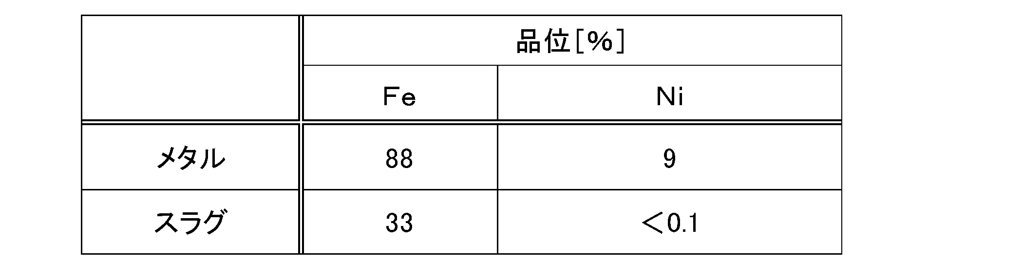
実施例1と同様の方法により原料を混合して混合物を得た後、乾燥ペレットを製造した。このとき、実施例3では、原料としての炭素質還元剤の混合量を、上述した化学当量の合計値100%に対して炭素量で70%の割合となる分の量とした。
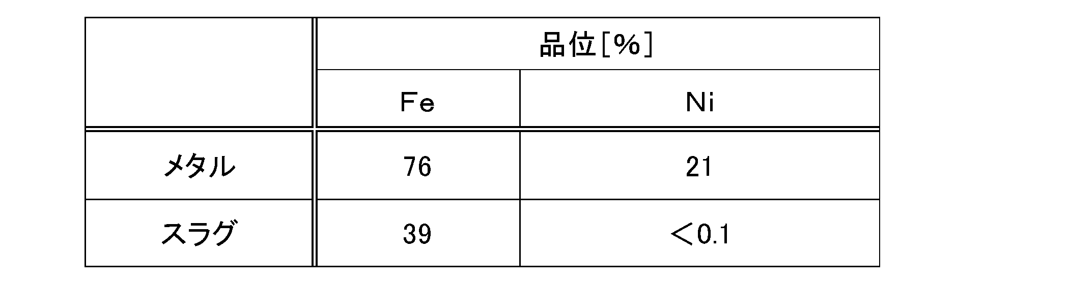
実施例3と同様にして混合物を得た後にペレットを製造し、同様の条件にてそのペレットに対して還元加熱処理を施した。
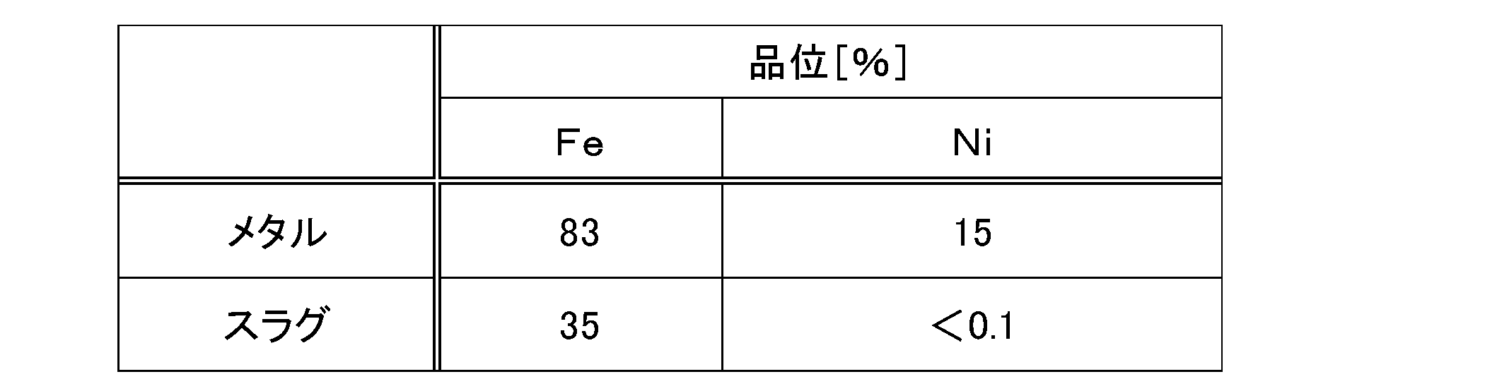
製錬炉において、炭素質還元剤である石炭粉を炉床に敷き詰めず、ペレットのみを製錬炉に装入して還元加熱処理を施したこと以外は、実施例1と同様にして行った。
実施例1と同様の方法により原料を混合して混合物を得た後、乾燥ペレットを製造した。このとき、比較例2では、原料としての炭素質還元剤の混合量を、上述した化学当量の合計値100%に対して炭素量で250%の割合となる分の量とした。

実施例1と同様の方法により原料を混合して混合物を得た後に乾燥ペレットを製造し、その炉床に敷き詰めた炉床炭素質還元剤の上に製造したペレット100個を載置させて装入した。なお、製錬炉へのペレットの装入に際しては、600℃以下の温度条件で行った。
実施例1と同様の方法により原料を混合して混合物を得た後に乾燥ペレットを製造し、その炉床に敷き詰めた炭素質還元剤の上に製造したペレット100個を載置させて装入した。なお、製錬炉へのペレットの装入に際しては、600℃以下の温度条件で行った。

実施例3と同様にして混合物を得た後にペレットを製造し、同様の条件にてそのペレットに対して還元加熱処理を施した。

実施例1と同様の方法により原料を混合して混合物を得た後、乾燥ペレットを製造した。このとき、比較例6では、原料としての炭素質還元剤の混合量を、上述した化学当量の合計値100%に対して炭素量で60%の割合となる分の量とした。
15 炭素質還元剤
20 ペレット
30 メタルシェル(シェル)
40 メタル粒
50 スラグ
Claims (5)
- ニッケル酸化鉱からペレットを形成し、該ペレットを還元加熱することによって、ニッケル品位が4%以上の鉄-ニッケル合金を得るニッケル酸化鉱の製錬方法であって、
前記ニッケル酸化鉱からペレットを製造するペレット製造工程と、
得られたペレットを製錬炉にて還元加熱する還元工程と
を有し、
前記ペレット製造工程では、少なくとも、前記ニッケル酸化鉱と、炭素質還元剤とを含む原料を混合して混合物とし、該混合物を塊状化してペレットを形成し、
前記還元工程では、得られたペレットを前記製錬炉に装入するにあたり、予め該製錬炉の炉床に炉床炭素質還元剤を敷き詰めて、該炉床炭素質還元剤上に該ペレットを載置した状態にして還元加熱処理を施す
ことを特徴とするニッケル酸化鉱の製錬方法。 - 前記還元工程では、前記炉床炭素質還元剤上に載置したペレットを、1350℃以上1550℃以下の加熱温度で還元加熱処理する
ことを特徴とする請求項1に記載のニッケル酸化鉱の製錬方法。 - 前記ペレットを前記製錬炉に装入する際の温度を600℃以下とする
ことを特徴とする請求項1に記載のニッケル酸化鉱の製錬方法。 - 前記ペレット製造工程では、
形成されるペレット内に含まれる酸化ニッケルをニッケルメタルに還元するのに必要な化学当量と、該ペレット内に含まれる酸化第二鉄を酸化第一鉄に還元するのに必要な化学当量との合計値を100%としたときに、70%以上200%以下の炭素量の割合となるように前記炭素質還元剤の混合量を調整する
ことを特徴とする請求項1に記載のニッケル酸化鉱の製錬方法。 - 前記還元工程における還元加熱処理の開始から前記ペレットを前記製錬炉から取り出すまでの時間を30分未満とする
ことを特徴とする請求項1に記載にニッケル酸化鉱の製錬方法。
Priority Applications (6)
| Application Number | Priority Date | Filing Date | Title |
|---|---|---|---|
| CN201580053382.7A CN106795585B (zh) | 2014-10-06 | 2015-09-15 | 镍氧化物矿的冶炼方法 |
| US15/517,046 US10364480B2 (en) | 2014-10-06 | 2015-09-15 | Method for smelting nickel oxide ore |
| CA2963461A CA2963461C (en) | 2014-10-06 | 2015-09-15 | Method for smelting nickel oxide ore |
| AU2015329325A AU2015329325B2 (en) | 2014-10-06 | 2015-09-15 | Method for smelting nickel oxide ore |
| EP15849480.7A EP3205732B1 (en) | 2014-10-06 | 2015-09-15 | Method for smelting nickel oxide ore |
| PH12017500616A PH12017500616A1 (en) | 2014-10-06 | 2017-04-04 | Method for smelting nickel oxide ore |
Applications Claiming Priority (2)
| Application Number | Priority Date | Filing Date | Title |
|---|---|---|---|
| JP2014205828A JP6314781B2 (ja) | 2014-10-06 | 2014-10-06 | ニッケル酸化鉱の製錬方法 |
| JP2014-205828 | 2014-10-06 |
Publications (1)
| Publication Number | Publication Date |
|---|---|
| WO2016056362A1 true WO2016056362A1 (ja) | 2016-04-14 |
Family
ID=55652983
Family Applications (1)
| Application Number | Title | Priority Date | Filing Date |
|---|---|---|---|
| PCT/JP2015/076197 Ceased WO2016056362A1 (ja) | 2014-10-06 | 2015-09-15 | ニッケル酸化鉱の製錬方法 |
Country Status (8)
| Country | Link |
|---|---|
| US (1) | US10364480B2 (ja) |
| EP (1) | EP3205732B1 (ja) |
| JP (1) | JP6314781B2 (ja) |
| CN (1) | CN106795585B (ja) |
| AU (1) | AU2015329325B2 (ja) |
| CA (1) | CA2963461C (ja) |
| PH (1) | PH12017500616A1 (ja) |
| WO (1) | WO2016056362A1 (ja) |
Cited By (5)
| Publication number | Priority date | Publication date | Assignee | Title |
|---|---|---|---|---|
| CN106086402A (zh) * | 2016-07-20 | 2016-11-09 | 江苏省冶金设计院有限公司 | 一种铬铁合金的生产方法 |
| WO2017183666A1 (ja) * | 2016-04-22 | 2017-10-26 | 住友金属鉱山株式会社 | 酸化鉱石の製錬方法 |
| JP2018178219A (ja) * | 2017-04-18 | 2018-11-15 | 住友金属鉱山株式会社 | 酸化鉱石の製錬方法 |
| US10626480B2 (en) | 2017-05-24 | 2020-04-21 | Sumitomo Metal Mining Co., Ltd. | Method for smelting oxide ore |
| US11608543B2 (en) | 2016-04-27 | 2023-03-21 | Sumitomo Metal Mining Co., Ltd. | Oxide ore smelting method |
Families Citing this family (5)
| Publication number | Priority date | Publication date | Assignee | Title |
|---|---|---|---|---|
| JP6953835B2 (ja) * | 2017-06-28 | 2021-10-27 | 住友金属鉱山株式会社 | 酸化鉱石の製錬方法 |
| JP7052239B2 (ja) * | 2017-07-19 | 2022-04-12 | 住友金属鉱山株式会社 | 酸化鉱石の製錬方法 |
| JP7415369B2 (ja) * | 2019-08-20 | 2024-01-17 | 住友金属鉱山株式会社 | 酸化鉱石の製錬方法 |
| JP7459660B2 (ja) * | 2020-05-27 | 2024-04-02 | 住友金属鉱山株式会社 | 酸化鉱石の製錬方法 |
| WO2024122482A1 (ja) * | 2022-12-08 | 2024-06-13 | 住友金属鉱山株式会社 | ニッケル酸化鉱石の製錬方法 |
Citations (6)
| Publication number | Priority date | Publication date | Assignee | Title |
|---|---|---|---|---|
| JPH0625770A (ja) * | 1991-12-03 | 1994-02-01 | Inco Ltd | ラテライト鉱石の低温熱的品質改良方法 |
| JP2001181720A (ja) * | 1999-12-28 | 2001-07-03 | Kobe Steel Ltd | 回転炉床炉による還元鉄製造方法 |
| JP2003239008A (ja) * | 2002-02-18 | 2003-08-27 | Jfe Steel Kk | 移動型炉床炉の操業方法および炉床耐火物保護用固体還元材 |
| JP2004156140A (ja) * | 2002-10-18 | 2004-06-03 | Kobe Steel Ltd | フェロニッケルおよびフェロニッケル精錬原料の製造方法 |
| JP2011256414A (ja) * | 2010-06-07 | 2011-12-22 | Kobe Steel Ltd | 粒状金属の製造方法 |
| WO2014080831A1 (ja) * | 2012-11-22 | 2014-05-30 | 株式会社神戸製鋼所 | 還元鉄の製造方法 |
Family Cites Families (13)
| Publication number | Priority date | Publication date | Assignee | Title |
|---|---|---|---|---|
| US3746533A (en) * | 1972-03-22 | 1973-07-17 | L Moussoulos | Process of producing ferro-nickel in a rotary furnace including pelletizing and pre-reducing ore |
| JPS6223944A (ja) | 1985-07-22 | 1987-01-31 | Nippon Yakin Kogyo Co Ltd | 酸化ニッケル鉱石からフェロニッケルルッペを製造する方法 |
| US6126718A (en) | 1999-02-03 | 2000-10-03 | Kawasaki Steel Corporation | Method of producing a reduced metal, and traveling hearth furnace for producing same |
| JP2001256414A (ja) * | 2000-03-14 | 2001-09-21 | Victor Co Of Japan Ltd | オンラインショッピングシステム及び同システムにおける代金支払い方法並びに同システムの受注用プログラムの記録された記録媒体 |
| JP4330257B2 (ja) * | 2000-08-09 | 2009-09-16 | 株式会社神戸製鋼所 | 金属鉄の製法 |
| JP4669189B2 (ja) | 2001-06-18 | 2011-04-13 | 株式会社神戸製鋼所 | 粒状金属鉄の製法 |
| US20040015443A1 (en) * | 2002-07-03 | 2004-01-22 | Mccoy Thomas C. | Flyer creator and dispersal system |
| WO2004035847A1 (ja) | 2002-10-18 | 2004-04-29 | Kabushiki Kaisha Kobe Seiko Sho | フェロニッケルおよびフェロニッケル精錬原料の製造方法 |
| CN100497670C (zh) * | 2006-12-22 | 2009-06-10 | 昆明贵金属研究所 | 一种转底炉快速还原含碳红土镍矿球团富集镍的方法 |
| EP2325341A1 (en) | 2008-01-30 | 2011-05-25 | Nu-Iron Technology, Inc | Methods and system für producing metallic ion nuggets |
| US8557019B2 (en) | 2008-02-08 | 2013-10-15 | Vale Inco Limited | Process for production of nickel and cobalt using metal hydroxide, metal oxide and/or metal carbonate |
| JP2010229525A (ja) | 2009-03-27 | 2010-10-14 | Kobe Steel Ltd | フェロニッケルおよびフェロバナジウムの製造方法 |
| US9306954B2 (en) * | 2011-06-30 | 2016-04-05 | Cloud Security Corporation | Apparatus, systems and method for virtual desktop access and management |
-
2014
- 2014-10-06 JP JP2014205828A patent/JP6314781B2/ja active Active
-
2015
- 2015-09-15 CN CN201580053382.7A patent/CN106795585B/zh not_active Expired - Fee Related
- 2015-09-15 US US15/517,046 patent/US10364480B2/en not_active Expired - Fee Related
- 2015-09-15 WO PCT/JP2015/076197 patent/WO2016056362A1/ja not_active Ceased
- 2015-09-15 AU AU2015329325A patent/AU2015329325B2/en active Active
- 2015-09-15 CA CA2963461A patent/CA2963461C/en not_active Expired - Fee Related
- 2015-09-15 EP EP15849480.7A patent/EP3205732B1/en active Active
-
2017
- 2017-04-04 PH PH12017500616A patent/PH12017500616A1/en unknown
Patent Citations (6)
| Publication number | Priority date | Publication date | Assignee | Title |
|---|---|---|---|---|
| JPH0625770A (ja) * | 1991-12-03 | 1994-02-01 | Inco Ltd | ラテライト鉱石の低温熱的品質改良方法 |
| JP2001181720A (ja) * | 1999-12-28 | 2001-07-03 | Kobe Steel Ltd | 回転炉床炉による還元鉄製造方法 |
| JP2003239008A (ja) * | 2002-02-18 | 2003-08-27 | Jfe Steel Kk | 移動型炉床炉の操業方法および炉床耐火物保護用固体還元材 |
| JP2004156140A (ja) * | 2002-10-18 | 2004-06-03 | Kobe Steel Ltd | フェロニッケルおよびフェロニッケル精錬原料の製造方法 |
| JP2011256414A (ja) * | 2010-06-07 | 2011-12-22 | Kobe Steel Ltd | 粒状金属の製造方法 |
| WO2014080831A1 (ja) * | 2012-11-22 | 2014-05-30 | 株式会社神戸製鋼所 | 還元鉄の製造方法 |
Non-Patent Citations (1)
| Title |
|---|
| See also references of EP3205732A4 * |
Cited By (7)
| Publication number | Priority date | Publication date | Assignee | Title |
|---|---|---|---|---|
| WO2017183666A1 (ja) * | 2016-04-22 | 2017-10-26 | 住友金属鉱山株式会社 | 酸化鉱石の製錬方法 |
| US11479832B2 (en) | 2016-04-22 | 2022-10-25 | Sumitomo Metal Mining Co., Ltd. | Method for smelting oxide ore |
| US11608543B2 (en) | 2016-04-27 | 2023-03-21 | Sumitomo Metal Mining Co., Ltd. | Oxide ore smelting method |
| CN106086402A (zh) * | 2016-07-20 | 2016-11-09 | 江苏省冶金设计院有限公司 | 一种铬铁合金的生产方法 |
| JP2018178219A (ja) * | 2017-04-18 | 2018-11-15 | 住友金属鉱山株式会社 | 酸化鉱石の製錬方法 |
| US10626480B2 (en) | 2017-05-24 | 2020-04-21 | Sumitomo Metal Mining Co., Ltd. | Method for smelting oxide ore |
| EP3636783A4 (en) * | 2017-05-24 | 2020-12-02 | Sumitomo Metal Mining Co., Ltd. | OXIDE ORE MELTING PROCESS |
Also Published As
| Publication number | Publication date |
|---|---|
| CN106795585A (zh) | 2017-05-31 |
| EP3205732A4 (en) | 2018-05-23 |
| EP3205732A1 (en) | 2017-08-16 |
| CN106795585B (zh) | 2019-03-15 |
| US10364480B2 (en) | 2019-07-30 |
| US20170306444A1 (en) | 2017-10-26 |
| AU2015329325B2 (en) | 2019-01-17 |
| JP6314781B2 (ja) | 2018-04-25 |
| CA2963461A1 (en) | 2016-04-14 |
| CA2963461C (en) | 2019-12-24 |
| PH12017500616A1 (en) | 2017-09-04 |
| AU2015329325A1 (en) | 2017-05-11 |
| JP2016074945A (ja) | 2016-05-12 |
| EP3205732B1 (en) | 2020-10-28 |
Similar Documents
| Publication | Publication Date | Title |
|---|---|---|
| JP5975093B2 (ja) | ニッケル酸化鉱の製錬方法 | |
| JP6314781B2 (ja) | ニッケル酸化鉱の製錬方法 | |
| JP6477371B2 (ja) | ニッケル酸化鉱の製錬方法 | |
| JP5958576B1 (ja) | サプロライト鉱の製錬方法 | |
| JP6447429B2 (ja) | ニッケル酸化鉱の製錬方法 | |
| JP5839090B1 (ja) | ニッケル酸化鉱の製錬方法、ペレットの装入方法 | |
| JP6428528B2 (ja) | ニッケル酸化鉱の製錬方法 | |
| JP6477349B2 (ja) | ニッケル酸化鉱の製錬方法 | |
| JP6455374B2 (ja) | ニッケル酸化鉱の製錬方法 | |
| JP6455359B2 (ja) | ニッケル酸化鉱の製錬方法 |
Legal Events
| Date | Code | Title | Description |
|---|---|---|---|
| 121 | Ep: the epo has been informed by wipo that ep was designated in this application |
Ref document number: 15849480 Country of ref document: EP Kind code of ref document: A1 |
|
| DPE1 | Request for preliminary examination filed after expiration of 19th month from priority date (pct application filed from 20040101) | ||
| ENP | Entry into the national phase |
Ref document number: 2963461 Country of ref document: CA |
|
| WWE | Wipo information: entry into national phase |
Ref document number: 15517046 Country of ref document: US |
|
| NENP | Non-entry into the national phase |
Ref country code: DE |
|
| REEP | Request for entry into the european phase |
Ref document number: 2015849480 Country of ref document: EP |
|
| ENP | Entry into the national phase |
Ref document number: 2015329325 Country of ref document: AU Date of ref document: 20150915 Kind code of ref document: A |