WO2016060076A1 - 多結晶シリコン破砕物、多結晶シリコン破砕物の製造方法および多結晶シリコン塊破砕装置 - Google Patents
多結晶シリコン破砕物、多結晶シリコン破砕物の製造方法および多結晶シリコン塊破砕装置 Download PDFInfo
- Publication number
- WO2016060076A1 WO2016060076A1 PCT/JP2015/078723 JP2015078723W WO2016060076A1 WO 2016060076 A1 WO2016060076 A1 WO 2016060076A1 JP 2015078723 W JP2015078723 W JP 2015078723W WO 2016060076 A1 WO2016060076 A1 WO 2016060076A1
- Authority
- WO
- WIPO (PCT)
- Prior art keywords
- polycrystalline silicon
- crushed material
- particle size
- crushed
- dust
- Prior art date
- Legal status (The legal status is an assumption and is not a legal conclusion. Google has not performed a legal analysis and makes no representation as to the accuracy of the status listed.)
- Ceased
Links
Images

Classifications
-
- B—PERFORMING OPERATIONS; TRANSPORTING
- B02—CRUSHING, PULVERISING, OR DISINTEGRATING; PREPARATORY TREATMENT OF GRAIN FOR MILLING
- B02C—CRUSHING, PULVERISING, OR DISINTEGRATING IN GENERAL; MILLING GRAIN
- B02C1/00—Crushing or disintegrating by reciprocating members
- B02C1/02—Jaw crushers or pulverisers
- B02C1/04—Jaw crushers or pulverisers with single-acting jaws
-
- B—PERFORMING OPERATIONS; TRANSPORTING
- B02—CRUSHING, PULVERISING, OR DISINTEGRATING; PREPARATORY TREATMENT OF GRAIN FOR MILLING
- B02C—CRUSHING, PULVERISING, OR DISINTEGRATING IN GENERAL; MILLING GRAIN
- B02C1/00—Crushing or disintegrating by reciprocating members
- B02C1/02—Jaw crushers or pulverisers
-
- B—PERFORMING OPERATIONS; TRANSPORTING
- B02—CRUSHING, PULVERISING, OR DISINTEGRATING; PREPARATORY TREATMENT OF GRAIN FOR MILLING
- B02C—CRUSHING, PULVERISING, OR DISINTEGRATING IN GENERAL; MILLING GRAIN
- B02C23/00—Auxiliary methods or auxiliary devices or accessories specially adapted for crushing or disintegrating not provided for in preceding groups or not specially adapted to apparatus covered by a single preceding group
- B02C23/08—Separating or sorting of material, associated with crushing or disintegrating
- B02C23/10—Separating or sorting of material, associated with crushing or disintegrating with separator arranged in discharge path of crushing or disintegrating zone
-
- B—PERFORMING OPERATIONS; TRANSPORTING
- B02—CRUSHING, PULVERISING, OR DISINTEGRATING; PREPARATORY TREATMENT OF GRAIN FOR MILLING
- B02C—CRUSHING, PULVERISING, OR DISINTEGRATING IN GENERAL; MILLING GRAIN
- B02C23/00—Auxiliary methods or auxiliary devices or accessories specially adapted for crushing or disintegrating not provided for in preceding groups or not specially adapted to apparatus covered by a single preceding group
- B02C23/18—Adding fluid, other than for crushing or disintegrating by fluid energy
- B02C23/24—Passing gas through crushing or disintegrating zone
- B02C23/30—Passing gas through crushing or disintegrating zone the applied gas acting to effect material separation
-
- C—CHEMISTRY; METALLURGY
- C01—INORGANIC CHEMISTRY
- C01B—NON-METALLIC ELEMENTS; COMPOUNDS THEREOF; METALLOIDS OR COMPOUNDS THEREOF NOT COVERED BY SUBCLASS C01C
- C01B33/00—Silicon; Compounds thereof
- C01B33/02—Silicon
-
- C—CHEMISTRY; METALLURGY
- C30—CRYSTAL GROWTH
- C30B—SINGLE-CRYSTAL GROWTH; UNIDIRECTIONAL SOLIDIFICATION OF EUTECTIC MATERIAL OR UNIDIRECTIONAL DEMIXING OF EUTECTOID MATERIAL; REFINING BY ZONE-MELTING OF MATERIAL; PRODUCTION OF A HOMOGENEOUS POLYCRYSTALLINE MATERIAL WITH DEFINED STRUCTURE; SINGLE CRYSTALS OR HOMOGENEOUS POLYCRYSTALLINE MATERIAL WITH DEFINED STRUCTURE; AFTER-TREATMENT OF SINGLE CRYSTALS OR A HOMOGENEOUS POLYCRYSTALLINE MATERIAL WITH DEFINED STRUCTURE; APPARATUS THEREFOR
- C30B15/00—Single-crystal growth by pulling from a melt, e.g. Czochralski method
- C30B15/02—Single-crystal growth by pulling from a melt, e.g. Czochralski method adding crystallising materials or reactants forming it in situ to the melt
-
- C—CHEMISTRY; METALLURGY
- C01—INORGANIC CHEMISTRY
- C01P—INDEXING SCHEME RELATING TO STRUCTURAL AND PHYSICAL ASPECTS OF SOLID INORGANIC COMPOUNDS
- C01P2004/00—Particle morphology
- C01P2004/60—Particles characterised by their size
-
- C—CHEMISTRY; METALLURGY
- C01—INORGANIC CHEMISTRY
- C01P—INDEXING SCHEME RELATING TO STRUCTURAL AND PHYSICAL ASPECTS OF SOLID INORGANIC COMPOUNDS
- C01P2006/00—Physical properties of inorganic compounds
- C01P2006/80—Compositional purity
Definitions
- the present invention relates to a polycrystalline silicon crushed material obtained by crushing a polycrystalline silicon lump, and more specifically, the content of polycrystalline silicon powder having a particle size of 500 to 1000 ⁇ m is reduced, the amount of fine silicon dust is small, and the surface metal
- the present invention relates to a polycrystalline silicon crushed material with reduced contamination. Furthermore, this invention relates to the polycrystalline silicon lump crushing apparatus used suitably for manufacture of said polycrystalline silicon crushed material.
- the Siemens method is known as a method for producing polycrystalline silicon, also called polysilicon.
- a silicon core wire disposed inside a bell jar type reaction vessel is heated to a silicon deposition temperature by energization, and gas and hydrogen of a silane compound such as trichlorosilane (SiHCl 3 ) or monosilane (SiH 4 ) are supplied thereto.
- silane compound such as trichlorosilane (SiHCl 3 ) or monosilane (SiH 4 ) are supplied thereto.
- silane compound such as trichlorosilane (SiHCl 3 ) or monosilane (SiH 4 ) are supplied thereto.
- SiHCl 3 trichlorosilane
- SiH 4 monosilane
- the obtained polycrystalline silicon rod is crushed and sorted into a size suitable for manufacturing an apparatus to be used in the next process or a manufacturing object in the next process, and conveyed to the next process.
- the polycrystalline silicon rod is crushed with a hammer made of a hard metal such as tungsten carbide to obtain a raw material polycrystalline silicon lump.
- the raw material polycrystalline silicon lump is further crushed to a desired particle size by a crushing device composed of hard polymer or hard metal, and then, if necessary, classified to a desired size by a classifying device made of the same material.
- a polycrystalline silicon crushed material having a desired particle size is obtained.
- the obtained polycrystalline silicon crushed material is called dust, powder, chip, nugget, chunk, etc. depending on its size, but there is no strict classification standard.
- particles having a particle size of less than 500 ⁇ m are referred to as “silicon dust”, and those having a particle size of 500 to 1000 ⁇ m are referred to as “polycrystalline silicon powder”.
- a crushed piece obtained by crushing a polycrystalline silicon lump including a crystalline silicon crushed piece is called a “polycrystalline silicon crushed material”.
- the rod and the crushed material come into contact with the crushing device and the sorting device, and contaminants from these devices adhere to the surface oxide layer on the surface.
- metal fines are generated due to wear inside the crushing device, and may adhere to the surface oxide layer of the crushed material and contaminate it. These are called surface metal contamination.
- the surface metal contamination tends to increase as the particle size of the crushed material decreases. In particular, the contamination adheres to silicon dust or polycrystalline silicon powder having a small particle size, thereby increasing the surface metal contamination.
- impurities such as metal fine powder generated by abrasion of a pulverizer or the like when fine particles are obtained by pulverization and the particle size is about 1000 ⁇ m or less. It is specified that the contamination becomes severe and it is necessary to perform wet chemical treatment in consideration of semiconductor applications (see paragraph [0009]). However, wet chemical processing is costly. Further, in the case of semiconductor applications, it has been shown that high purity cannot be sufficiently achieved even with the above-described wet chemical treatment for silicon dust or polycrystalline silicon powder having a particle size reduced to 1000 ⁇ m or less.
- polycrystalline silicon used for applications such as the manufacture of solar panels does not require the extremely high purity as described above. For this reason, depending on the application, if the amount of silicon dust or surface metal contamination is less than the allowable value, priority may be given to cost reduction without excessively increasing the purity.
- Patent Document 2 Japanese Patent Laid-Open No. 2012-46412 discloses that compressed silicon or dry ice is sprayed on polycrystalline silicon after crushing and classification to remove silicon dust. A method has been proposed.
- silicon dust is removed by the wind pressure, but at the same time, silicon crushed material having a particle size larger than that of silicon dust jumps up or collides with each other. Silicon dust and polycrystalline silicon powder may be generated. Further, when the silicon rod is crushed, an oxide film is formed on the fracture surface of the crushed material. If silicon dust or polycrystalline silicon powder adheres to this oxide film, the oxide film on the surface layer and the oxide film on the fracture surface of the crushed material will be integrated, and it will be difficult to remove these silicon dust and polycrystalline silicon powder. Is done. Furthermore, even if compressed air is blown in a state where polycrystalline silicon is stacked after classification, silicon dust and polycrystalline silicon powder that have entered the gaps between the crushed materials that are stacked cannot be sufficiently removed.
- Patent Document 2 silicon dust having a particle size of less than 400 ⁇ m is targeted for removal.
- a crushed material having a particle size of 500 ⁇ m (0.5 mm) or more is recognized as a product and is not a removal target.
- the particle size is about 500 ⁇ m to 1 mm and the particle size is called “polycrystalline silicon powder” in the present invention, as shown in the above-mentioned Patent Document 1, the metal impurities are still mixed, and the present inventors Have examined the following problems.
- Polycrystalline silicon fragments may be used to produce single crystal silicon ingots.
- a single crystal ingot it is necessary to smoothly fill the melted container with the crushed polycrystalline silicon.
- polycrystalline silicon powder of about 500 ⁇ m to 1 mm is contained, the fluidity of the polycrystalline silicon crushed material is impaired, and smooth introduction into the melting container may be hindered.
- CZ Czochralski
- a powder of about 500 ⁇ m to 1 mm may not be easily melted, and becomes a nucleus for crystal formation, and the ingot may be polycrystallized. For this reason, in order to produce a single crystal ingot, it is necessary to remelt the polycrystallized ingot and to pull it up again, which leads to a decrease in productivity.
- Patent Document 3 Japanese Patent Laid-Open No. 2009-78961 discloses a technique for removing static electricity by blowing ionized clean air onto polycrystalline silicon in order to prevent dust from adhering to charged polycrystalline silicon. Yes.
- an external force load member for the polycrystalline silicon rod specifically a jaw crusher is used. If so, it has been attempted to make the material of the movable teeth and fixed teeth with a hard metal such as tungsten carbide (for example, Japanese Patent Application Laid-Open No. 2004-161595).
- An apparatus for producing a silicon pulverized product is disclosed in which polycrystalline silicon is pulverized and classified by a pulverizer equipped with a hard pulverization tool.
- Patent Document 2 discloses a technique for removing silicon dust having a particle size of less than 400 ⁇ m from polycrystalline silicon by spraying compressed air or dry ice.
- polycrystalline silicon powder having a particle size of about 500 ⁇ m to 1 mm is regarded as a product and is not an object of removal.
- silicon fine particles having a particle size of about 500 ⁇ m to 1 mm are a factor that impairs operability and productivity particularly in the production of a single crystal silicon ingot.
- the present invention provides a polycrystalline silicon crushed material from which polycrystalline silicon powder having a particle size of about 500 ⁇ m to 1 mm is removed, and which can contribute to improvement in operability and productivity particularly in the production of a single crystal silicon ingot. It is an object.
- the material of the external force load member is made of a hard metal such as tungsten carbide, the surface metal contamination of the obtained polycrystalline silicon crushing material is sufficiently reduced.
- a polycrystalline silicon lump crusher that can reduce surface metal contamination to a satisfactory level has not been realized.
- the present invention can reduce the adhesion of metal to crushed polycrystalline silicon during crushing, and provides a method for producing the above-mentioned polycrystalline silicon crushed material and a polycrystalline silicon lump crushing device suitable for the production thereof. It is an object.
- the present inventors diligently studied to solve the above-mentioned problems. As a result, the polycrystalline silicon crushed in the crushing apparatus is efficiently dropped to obtain a polycrystalline silicon powder of about 500 ⁇ m to 1 mm by suction. As a result, the present invention was completed.
- the polycrystalline silicon crushed material is a polycrystalline silicon crushed material obtained by crushing a polycrystalline silicon lump,
- the content ratio of polycrystalline silicon powder having a particle size of 500 to 1000 ⁇ m is 0.1 to 40 ppmw.
- the polycrystalline silicon crushed material may contain 3 to 140 ppmw of silicon dust having a particle size of less than 500 ⁇ m.
- 90% by mass or more of the polycrystalline silicon crushed material may have a particle size of 2 to 90 mm.
- the polycrystalline silicon crushed material 90% by weight or more of the polycrystalline silicon crushed material has a particle size of 4 to 60 mm, and the content ratio of polycrystalline silicon powder having a particle size of 500 to 1000 ⁇ m is 1 to 30 ppmw. Furthermore, the content ratio of silicon dust having a particle size of less than 500 ⁇ m may be 10 to 60 ppmw.
- the polycrystalline silicon crushed material 90% by weight or more of the polycrystalline silicon crushed material has a particle size of 2 to 40 mm, and the content ratio of the polycrystalline silicon powder having a particle size of 500 to 1000 ⁇ m is 2 to 40 ppmw. Furthermore, the content ratio of silicon dust having a particle size of less than 500 ⁇ m may be 20 to 140 ppmw.
- the crushed polycrystalline silicon 90% by weight or more of the crushed polycrystalline silicon has a particle size of 20 to 90 mm, and the content ratio of polycrystalline silicon powder having a particle size of 500 to 1000 ⁇ m is 0.5. Furthermore, the content of silicon dust having a particle size of less than 500 ⁇ m may be 5 to 50 ppmw.
- the crushed polycrystalline silicon may have a metal surface contamination of 0.5 to 50 ppbw, and the metal having a surface contamination is composed of Na, Cr, Fe, Ni, Cu, Zn, Co and W. Groups may be included.
- the polycrystalline silicon lump crusher according to the present invention is The raw material polycrystalline silicon lump charged from the raw material inlet is mechanically crushed by the movement of the external force loading member to produce a polycrystalline silicon crushed material containing polycrystalline silicon powder having a particle size of 500 to 1000 ⁇ m.
- a crushing section to be taken out from the discharge port;
- a drop moving unit that continues below the crushing unit, and that drops and moves the polycrystalline silicon crushed material from the discharge port according to gravity;
- a receiving portion that is located below the falling moving portion and receives the polycrystalline silicon crushed material after the falling moving portion has been dropped and moved;
- the drop moving unit has a suction removal unit that sucks and removes at least a part of the polycrystalline silicon powder accompanying the polycrystalline silicon crushed material in a direction different from the direction of the drop movement.
- the external force load member has movable movable teeth and fixed stationary teeth
- the crushing unit is configured to supply the raw material polycrystalline silicon lump supplied from the upper raw material input port
- a structure may be adopted in which the movable teeth and the fixed teeth are sandwiched between the teeth and crushed, and this is discharged from the lower discharge port.
- the polycrystalline silicon lump crushing device may have a sliding dust suction part that sucks sliding dust generated from a sliding part that slides as the external force load member moves.
- the method for producing a polycrystalline silicon crushed material according to the present invention may use the polycrystalline silicon lump crushing device described above.
- the method for producing a polycrystalline silicon crushed material may include an air blowing step of blowing air to the polycrystalline silicon crushed material received by the receiving portion.
- the polycrystalline silicon crushed material according to the present invention can be obtained by the above-described method for producing a polycrystalline silicon crushed material.
- the present inventors have not only caused the surface metal contamination of the polycrystalline silicon crushed material obtained by the polycrystalline silicon lump crushing apparatus, but also the external force load member that crushes the polycrystalline silicon lump. It was ascertained that the amount of sliding dust from the sliding portion that slides by the movement of the load member scatters and adheres to the surface of the crushed material is also a considerable amount. And based on this knowledge, in the polycrystalline silicon lump crushing device, the surface metal contamination of the obtained polycrystalline silicon crushed material can be further reduced by providing the sliding dust suction part for sucking the sliding dust. I found.
- Such a polycrystalline silicon lump crusher is a polycrystal silicon crushing product that mechanically crushes a raw material polycrystalline silicon lump by moving an external force load member that applies external force to the raw material polycrystalline silicon lump.
- the crystal silicon lump crusher It has a sliding part which slides by the movement of the external force load member, and has a sliding dust suction part which sucks the sliding dust generated from the sliding part.
- the crushed polycrystalline silicon crushed material falls freely within the crushing apparatus.
- suction is performed in a direction different from the falling direction, not only fine silicon dust but also polycrystalline silicon powder having a relatively large particle size can be efficiently removed.
- This is a state before the polycrystalline silicon crushed material is piled up and the polycrystalline silicon powder or silicon dust enters the gap between the relatively large crushed materials. Since most of the silicon dust is sucked in a state of being scattered in the crushed material, it is considered that the polycrystalline silicon powder can also be efficiently removed.
- the polycrystalline silicon crushed material is immediately after crushing, and no oxide film is formed on the fracture surface, and polycrystalline silicon powder or silicon dust may be integrally attached to the surface oxide film. It is thought that there is also an influence of not having.
- the obtained polycrystalline silicon crushed material significantly reduces the content of polycrystalline silicon powder having a particle size of 500 to 1000 ⁇ m, and thus can contribute to improvement in operability and productivity particularly when producing a single crystal silicon ingot. .
- the sliding dust generated from the sliding part is Efficient suction removal. Therefore, the amount of sliding dust scattered in the apparatus can be reduced, and adhesion to the surface of the manufactured polycrystalline silicon crushed material can be greatly suppressed. As a result, a polycrystalline silicon crushed material with a highly reduced surface metal contamination can be obtained efficiently.
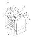
- FIG. 1 is a schematic perspective view of a polycrystalline silicon lump crusher according to an embodiment of the present invention.
- FIG. 2 is a conceptual diagram showing a cross-sectional structure of the polycrystalline silicon lump crusher shown in FIG.
- the polycrystalline silicon crushed material according to the present invention contains polycrystalline silicon powder having a particle size of 500 to 1000 ⁇ m.
- the polycrystalline silicon crushed material is obtained by crushing a raw material polycrystalline silicon lump to a desired particle size.
- the raw material polycrystalline silicon lump may be obtained by any method, but in general, a polycrystalline silicon rod obtained by the Siemens method is crushed with a hammer made of a hard metal such as tungsten carbide. can get.
- Crushed polycrystalline silicon lump is obtained by crushing the raw material polycrystalline silicon lump with a polycrystalline silicon lump crusher as described later. At the time of crushing, in addition to silicon dust, polycrystalline silicon powder with particle size of 500 ⁇ 1000 ⁇ m is generated To do.
- the ratio of polycrystalline silicon powder having a particle size of 500 to 1000 ⁇ m is reduced to 0.1 to 40 ppmw, preferably 3 to 35 ppmw.
- the particle size of the polycrystalline silicon powder means a powder state that passes through a 1000 ⁇ m mesh filter and is collected on a 500 ⁇ m mesh filter, and its content is recovered from the 500 ⁇ m mesh filter. It is calculated from the mass of the fine powder. Specifically, it is measured by the method described in the examples described later.
- ppmw means parts per million on a weight basis
- ppbw means parts per billion on a weight basis
- the polycrystalline silicon crushed material of the present invention can contribute to improvement in operability and productivity particularly in the production of a single crystal silicon ingot. It is difficult to reduce the amount of polycrystalline silicon powder having a particle size of 500 to 1000 ⁇ m to less than 0.1 ppmw by means other than high-cost wet chemical treatment, and further improve the operability and productivity in the production of silicon ingots. It cannot be expected and its economic significance is low.
- the amount of polycrystalline silicon powder having a particle size of 500 to 1000 ⁇ m exceeds 40 ppmw, the fluidity is impaired, and the single crystal silicon ingot obtained using this may be polycrystallized.
- the polycrystalline silicon crushed material has a controlled particle size distribution.
- the polycrystalline silicon crushed material is preferably used as a raw material for growing a silicon single crystal, filled in a melting container, and melted, pulled up and the like.
- the polycrystalline silicon crushed material having a controlled particle size distribution has a constant fluidity and can be stably supplied when filled into the melting vessel.
- ⁇ Crushed polycrystalline silicon is called dust, powder, chip, nugget, chunk, etc. depending on its size, but there is no strict classification standard.
- the polycrystalline silicon crushed material of the present invention is generally called a chip or a chunk, but also includes a nugget.
- the polycrystalline silicon crushed material preferably has a particle size suitable for the supply device to the melting container, and is appropriately set depending on the specifications of the supply device. Moreover, it is preferable that the polycrystalline silicon crushed material has a particle size according to its use.
- the crushed polycrystalline silicon may be selected and classified so as to have a desired particle size and particle size distribution after crushing. However, a small amount of polycrystalline silicon powder is also contained in the crushed silicon after classification.
- the particle size distribution of the polycrystalline silicon crushed material is not particularly limited, and is usually selected from a wide range of 2 to 120 mm.
- the range of particle size distribution disclosed herein discloses not only the range itself but also any range encompassed by the range, including the boundaries of the range.
- the disclosure of the range of 2 to 40 mm includes not only the range of 2 to 40 mm, but also 3 mm, 4 mm, 5 mm, 6 mm, 7 mm, 34 mm and 35 mm and other numerical values included in this range.
- 2 to 5 mm and 2 to 35 mm are included in the same manner as other partial ranges included in the range, and the ranges disclosed herein are also included. Equivalent ranges are included as well.
- the particle size of the crushed polycrystalline silicon means the major axis of the crushed material, and the particle size distribution is obtained by measuring the crushed material for 5 kg with a measuring instrument such as a caliper.
- the polycrystalline silicon crushed material of the present invention is preferably not only a small content ratio of the polycrystalline silicon powder having a particle size of 500 to 1000 ⁇ m but also a small content ratio of silicon dust having a particle size of less than 500 ⁇ m.
- the ratio is particularly preferably 3 to 140 ppmw.
- a small content of silicon dust is preferable because surface metal contamination is easily reduced.
- reducing silicon dust below the lower limit is not efficient from the viewpoint of the balance between purity and economy.
- the particle size of silicon dust means a fine particle size powder state that passes through a 500 ⁇ m mesh filter, and the content thereof is before and after collecting the fine powder collected by a 1 ⁇ m mesh filter paper. It is measured from the difference in filter paper mass. Specifically, it is measured by the method described in the examples described later.
- the preferred polycrystalline silicon crushed material of the present invention has a particle size of 90 to 90% by weight of 2 to 90 mm, and the content of polycrystalline silicon powder having a particle size of 500 to 1000 ⁇ m is 0.1 to 40 ppmw, particularly preferably. Furthermore, the content of silicon dust having a particle size of less than 500 ⁇ m is 3 to 140 ppmw, particularly preferably 10 to 120 ppmw.
- polycrystalline silicon crushed material of the present invention 90% by weight or more thereof has a particle size of 4 to 60 mm, and the content ratio of polycrystalline silicon powder having a particle size of 500 to 1000 ⁇ m is 1 to 30 ppmw, particularly preferably.
- the content of silicon dust having a particle size of less than 500 ⁇ m is 10 to 60 ppmw, particularly preferably 15 to 50 ppmw.
- polycrystalline silicon crushed material of the present invention 90% by weight or more thereof has a particle size of 2 to 40 mm, and the content ratio of polycrystalline silicon powder having a particle size of 500 to 1000 ⁇ m is 2 to 40 ppmw, particularly preferably. Further, the content of silicon dust having a particle size of less than 500 ⁇ m is preferably 20 to 140 ppmw, particularly preferably 30 to 120 ppmw.
- 90% by weight or more thereof has a particle size of 20 to 90 mm, and the content of polycrystalline silicon powder having a particle size of 500 to 1000 ⁇ m is 0.5 to 25 ppmw, particularly The content is preferably 3 to 20 ppmw, and the content of silicon dust having a particle size of less than 500 ⁇ m is preferably 5 to 50 ppmw, particularly preferably 10 to 40 ppmw.
- the preferred polycrystalline silicon crushed material of the present invention has reduced metal contamination of the surface oxide layer. That is, the surface contamination with metal is 0.5 to 50 ppbw, more preferably 2 to 40 ppbw. As described above, surface metal contamination is also reduced by removing polycrystalline silicon powder and further silicon dust from polycrystalline silicon. In particular, since the metal derived from the apparatus tends to adhere to silicon dust having a particle size of less than 500 ⁇ m, surface metal contamination is greatly reduced by reducing this. However, it is usually difficult to make the value so low that it can be reduced by wet chemical treatment. Depending on the use of polycrystalline silicon, such as the manufacture of solar panels, if the surface metal contamination is less than the allowable amount, priority may be given to cost reduction without excessively increasing the purity. For this reason, if the lower limit of surface metal contamination is the said range, it can be usefully used for such a use.
- the surface contamination metal of the polycrystalline silicon of the present invention preferably includes a group consisting of Na, Cr, Fe, Ni, Cu, Zn, Co and W.
- the surface metal contamination is measured by the method described in Examples described later.
- the bulk impurities of boron, phosphorus, carbon and all metals are suppressed to a very low concentration.
- the bulk impurity means an impurity inevitably contained in the rod, the silicon lump, or the silicon crushed material depending on the manufacturing conditions, and is different from the surface metal contaminant.
- the concentration of bulk impurities for a given metal is sufficiently low compared to surface metal contaminants, or if silicon fragments are obtained from the same polycrystalline silicon rod, the presence of bulk impurities is permitted. May be considered within the error range.
- the surface contamination by the metal of the polycrystalline silicon crushed material is 0.5 to 50 ppbw, particularly preferably 2 to 40 ppbw when 90% by weight or more of the crushed material has a particle size of 2 to 90 mm.
- 90% by weight or more of the crushed material has a particle size of 4 to 60 mm, it is preferably 2 to 30 ppbw, particularly preferably 3 to 15 ppbw.
- 90% by weight or more of the crushed material has a particle size of 2 to 40 mm, it is preferably 10 to 50 ppbw, particularly preferably 15 to 30 ppbw.
- 90% by weight or more of the crushed material has a particle size of 20 to 90 mm, it is preferably 1 to 10 ppbw, particularly preferably 2 to 8 ppbw.
- the polycrystalline silicon crushed material of the present invention may be sorted based on the particle size, if necessary, or a desired particle size and particle size distribution may be achieved using a sorting machine or a classifier. Furthermore, the polycrystalline silicon crushed material may be subjected to an impurity removal treatment using magnetic force or air blow as an optional treatment.
- the content of the polycrystalline silicon powder and the preferable content of silicon dust without performing wet chemical cleaning using an acid.
- the wet chemical cleaning is not performed, the surface metal contamination of the polycrystalline silicon crushed material is difficult to reduce beyond the lower limit, but it can be used favorably for applications such as the manufacture of solar panels.
- the method for obtaining the polycrystalline silicon crushed material of the present invention is not particularly limited, it is preferably carried out by a method using a polycrystalline silicon lump crusher as described below. That is, the raw material polycrystalline silicon lump charged from the raw material inlet is mechanically crushed by the movement of the external force loading member to produce a polycrystalline silicon crushed material containing polycrystalline silicon powder having a particle size of 500 to 1000 ⁇ m, A crushing section for discharging this from the discharge port; A drop moving unit that continues below the crushing unit, and that drops and moves the polycrystalline silicon crushed material from the discharge port according to gravity; A receiving portion that is located below the falling moving portion and receives the polycrystalline silicon crushed material after the falling moving portion has been dropped and moved; The drop moving unit has a suction removal unit that sucks and removes at least a part of the polycrystalline silicon powder contained in the polycrystalline silicon crushed material in a direction different from the falling movement direction. This is a method using a polycrystalline silicon lump crusher.
- the crushing part is configured to move the raw material polycrystalline silicon lump charged from the upper charging port by the external force load member having movable movable teeth and fixed fixed teeth.
- the efficiency of crushing is the so-called crushing part structure of a crushing device called a jaw crusher, which has a structure that crushes between teeth and the fixed tooth and then discharges the generated crushed material from the lower discharge port. Is preferable.
- the crushing part of the polycrystalline silicon lump crushing device is a so-called roll crusher having a structure that breaks the raw material polycrystalline silicon lump through two rolls that rotate in opposite directions as the external force load member.
- the crushing part structure of the crushing device called, and further, the crushing called so-called hammer crusher, which is a structure in which the raw material polycrystalline silicon lump is struck by the head of the swinging hammer that is the external force loading member.
- the crushing part structure of an apparatus etc. may be sufficient.
- FIG. 1 is an external view of a jaw crusher 10 having such a structure
- FIG. 2 is a schematic cross-sectional view showing an internal structure of the jaw crusher 10.
- the jaw crusher 10 includes a crushing unit 30 that crushes the raw material polycrystalline silicon lump 83, a drop moving unit 32 in which the polycrystalline silicon crushed material 93 produced by the crushing unit 30 moves and drops, And a receiving portion 34 for receiving the polycrystalline silicon crushed material 85 after falling and moving the moving portion 32.
- the raw material polycrystalline silicon lump 83 charged into the crushing unit 30 from the charging port 30 a above the crushing unit 30 is sandwiched between the movable movable tooth 24 and the fixed fixed tooth 14 to be crushed.
- the crushed polycrystalline silicon 93 before passing through the drop moving unit 32 is generated.
- the polycrystalline silicon crushed material 93 contains more polycrystalline silicon powder 91a and silicon dust 91b than the polycrystalline silicon crushed material 85 described later.
- the raw material polycrystalline silicon lump 83 may be manufactured by roughly dividing a polycrystalline silicon rod manufactured by the Siemens method or the like to a size that can be put into the jaw crusher 10 using a hard metal hammer or the like.
- the fixed teeth 14 are fixed to the front frame 12.
- the movable tooth 24 is fixed to the swing jaw 22 provided in the central part of the jaw crusher 10.
- the upper part of the swing jaw 22 to which the movable tooth 24 is fixed is attached to the eccentric shaft 20, and the swing jaw 22 and the movable tooth 24 fixed to the swing jaw 22 swing along with the eccentric rotation of the eccentric shaft 20.
- Both sides of the eccentric shaft 20 (both sides in the depth direction in FIG. 2) are connected to a driving pulley 60 via a rotation shaft (not shown) that is not eccentric.
- the driving pulley 60 rotates upon receiving a driving force from a driving electric motor (not shown).
- the swinging jaw 22 and the movable teeth 24 that swing are supported by bearings from both sides.
- a toggle plate 50 and a tension rod 54 are connected to the lower end of the swing jaw 22.
- the toggle plate 50 connects the lower end of the swing jaw 22 and the plate receiver 52 fixed to the rear frame so as to be relatively movable.
- a tension spring 56 is attached to the tension rod 54 to urge the lower end portion of the swing jaw 22 in a direction away from the fixed tooth 14.
- the polycrystalline silicon crushed material 93 generated in the crushing unit 30 is discharged from the discharge port 30 b below the crushing unit 30.
- the drop moving unit 32 continues below the discharge port 30b, and the polycrystalline silicon crushed material 93 that has come out of the discharge port 30b drops and moves in the drop moving unit 32 according to gravity.
- the drop moving unit 32 includes a discharge port cover 28 that covers the discharge port 30b.
- the drop moving unit 32 includes a suction removal unit 40 located in the middle of the dropping movement path of the polycrystalline silicon crushed material 93.
- the suction direction of the suction removal unit 40 is a direction different from the falling movement direction of the polycrystalline silicon crushed material 93.
- the suction direction of the suction removal unit 40 is not particularly limited, as shown in FIG. 2, the falling direction is a substantially vertical direction, and the suction direction of the suction removal unit 40 is a substantially horizontal direction as indicated by an arrow 92. It is preferable.
- the suction removing unit 40 removes at least a part of the polycrystalline silicon powder 91a and the silicon dust 91b contained in the polycrystalline silicon crushed material 93 in a direction different from the falling direction of the remaining polycrystalline silicon crushed material 93. To do. Thereby, the polycrystalline silicon powder 91a and the silicon dust 91b contained in the polycrystalline silicon crushed material 93 are reduced, and the amount of fine particles and impurities contained in the polycrystalline silicon crushed material 93 can be reduced. Furthermore, the important point is that not only the silicon dust 91b but also the polycrystalline silicon powder 91a which is difficult to remove after the polycrystalline silicon crushed material 93 falls and piles up can be highly removed by the suction from the suction removing unit 40. It is.
- the suction removing unit 40 effectively removes the polycrystalline silicon powder 91a as well as the silicon dust 91b by sucking the falling polycrystalline silicon crushed material 93 immediately after crushing, and passes through the falling moving unit 32.
- the amount of impurities contained in the crushed polycrystalline silicon crushed material 85 can be reduced.
- the drop density of the polycrystalline silicon crushed material 93 falling on the drop moving unit 32 is appropriate, and further, the polycrystalline silicon falling at this drop density
- the suction force applied to the crushed material 93 is required to be sufficiently strong.
- the supply amount of the crushed polycrystalline silicon 93 to the drop moving unit 32 is preferably 20 to 160 g / min per unit sectional area (cm 2 ) of the drop moving unit 32, and preferably 30 to 130 g / min.
- the diameter of the suction removing section 40 is preferably 2 to 40% of the sectional area of the portion of the drop moving section 32 where the suction removing section 40 is provided, and preferably 3 to 30%. It is more preferable that the air is sucked from the suction removal section 40 having a diameter of 1 to 20 m 3 / min, more preferably 2 to 15 m 3 / min.
- the drop moving part 32 is provided with a length of 20 to 80 cm, and more preferably with a length of 30 to 70 cm.
- the suction removing unit 40 may be provided at two or more locations in the circumferential direction and the length direction of the drop moving unit 32.
- the suction removal unit 40 is not particularly limited as long as it generates or transmits suction force and can suck the polycrystalline silicon powder 91a.
- a suction pipe connected to a negative pressure forming pump (not shown) The removal unit 40 can be employed.
- the crushed polycrystalline silicon 85 after being dropped and moved by the drop moving part 32 is received by the receiving part 34 located below the drop moving part 32.
- the receiving portion 34 may be configured by a belt conveyor capable of transporting the polycrystalline silicon crushed material 85, but may be a storage box for storing the polycrystalline silicon crushed material 85. Absent.
- the polycrystalline silicon crushed material 85 of the present invention in which the content ratio of the polycrystalline silicon powder having a particle size of 500 to 1000 ⁇ m is 0.1 to 40 ppmw can be produced.
- the polycrystalline silicon crushed material 85 received by the receiving portion 34 is conveyed to a classification process or the like.
- the jaw crusher 10 has sliding dust suction portions 42, 44, and 46 that suck sliding dust generated from sliding portions that slide as the movable teeth 24 move.
- the specific configuration of the sliding dust suction unit is not particularly limited as long as it sucks the sliding dust.
- the sliding dust suction unit is connected to a cover or the like that covers the sliding unit, and includes a suction tube that sucks the sliding dust.
- the sliding dust suction part 42 is constituted by a suction pipe connected to the central cover 26.
- the center cover 26 is provided at the upper center of the jaw crusher 10 and covers the swing jaw 22, the eccentric shaft 20, the rotation shaft, and the like, and the sliding dust suction portion 42 includes the swing jaw 22, the eccentric shaft 20, and the rotation. The sliding dust generated from the shaft is sucked.
- the sliding dust suction part 44 is configured by a suction pipe connected to the side cover 62 that covers the driving pulley 60 and sucks the sliding dust generated from the driving pulley 60.
- the sliding dust suction part 46 is constituted by a suction pipe connected to a rear cover 58 that covers the toggle plate 50, the tension rod 54, and the like. The sliding dust generated from connecting parts such as frames is sucked.
- the jaw crusher 10 provided with such sliding dust suction parts 42, 44, 46 can reduce the amount of impurities contained in the generated polycrystalline silicon crushed material 85, and is particularly contained in sliding dust. It is possible to effectively prevent surface contamination of the polycrystalline silicon crushed materials 93 and 85 by metal. Further, the suction removal unit 40 sucks the sliding dust generated inside the jaw crusher 10, thereby preventing the problem of increasing the chance of contact between the sliding dust and the polycrystalline silicon crushed materials 93 and 85. In order to sufficiently enhance the suction effect of the sliding dust from the sliding dust suction portions 42, 44, 46, the diameter of the sliding dust suction portion 42 is set to 0. 0 relative to the inner volume of the central cover 26.
- the diameter of the sliding dust suction portion 44 is preferably 0.1 to 1.5 mm / L, preferably 0.3 to 1.3 mm / L with respect to the inner volume of the side cover 62 that covers the driving pulley 60. It is more preferable that air is sucked from the sliding dust suction portion 44 having this diameter at a suction amount of 0.5 to 5 m 3 / min, more preferably 1 to 3 m 3 / min.
- the diameter of the sliding dust suction portion 46 is preferably 0.2 to 5 mm / L, and preferably 0.5 to 4 mm / L with respect to the inner volume of the rear cover 58 that covers the toggle plate 50, the tension rod 54, and the like. More preferably, the suction is preferably performed at a suction amount of 1 to 20 m 3 / min, more preferably 2 to 15 m 3 / min. Decreasing the amount of suction below the lower limit is not preferable because a sufficient suction effect cannot be obtained. Moreover, increasing beyond the above upper limit is not efficient from the viewpoint of the balance between surface metal contamination and economy.
- the aspect of the sliding part which is the target of suction by the sliding suction part is not particularly limited, and the sliding part constituted by a shaft and a bearing, a member that performs a linear or arc-shaped reciprocating motion, and this are supported.
- the sliding part etc. which are comprised with a member are illustrated.
- the sliding portion that is a target of suction by the sliding suction portion may be a combination of a movable member and a stationary member, or may be constituted by two movable members.
- the jaw crusher 10 is constituted by a suction pipe connected to the charging port cover 16 covering the charging port 30a, and has a charging port suction part 48 for sucking dust and the like that rises at the time of crushing in the crushing part 30. Yes.
- the suction amount of the inlet suction part 48 is preferably 0.5 to 5 m 3 / min, more preferably 1 to 3 m 3 / min.
- a part or all of the suction removing unit 40, the sliding dust suction units 42, 44, 46, and the inlet suction unit 48 described above may be connected to a common negative pressure forming pump, and different negative pressure generations may be performed. It may be connected to a pump.
- the polycrystalline silicon crushed material obtained in this way is preferable because surface metal contamination is reduced. That is, by providing the sliding dust suction parts 42, 44, and 46 as shown in the embodiment, it is possible to reduce the surface contamination of the obtained polycrystalline silicon crushed material by metal to about 0.5 to 50 ppbw. .
- the sliding dust suction portion according to the present embodiment is combined with other surface metal contamination prevention means such as a hard metal material of the external force load member (the fixed tooth 14 and the movable tooth 24 in the present embodiment). It is possible to further reduce the surface metal contamination of the obtained polycrystalline silicon crushed material. Also in an aspect combined with other means for preventing surface metal contamination, the surface contamination of the polycrystalline silicon lump obtained by the polycrystalline silicon lump crusher having the sliding dust suction part is preferably 0.5 to 50 ppbw. Yes, more preferably 2 to 40 ppbw.
- the surface metal contamination of the polycrystalline silicon crushed material can be further reduced by subjecting the crushed material obtained by the polycrystalline silicon lump crushing device to wet chemical treatment with an acid.
- the obtained crushed material is further subjected to wet chemical treatment.
- the crushed material before the wet chemical treatment is prepared using the polycrystalline silicon lump crusher of the present invention, so that the degree of the wet chemical treatment can be reduced.
- the polycrystalline silicon crushed material has applications in which excessive purity is not required and cost is important, such as a solar panel manufacturing raw material.
- surface metal contamination in the obtained polycrystalline silicon crushed material even without wet chemical treatment.
- the value of can be made below the allowable value. That is, the polycrystalline silicon crushed material obtained by the polycrystalline silicon lump crushing device of the present invention can be usefully used for such applications without performing the above-described wet chemical treatment. The accompanying environmental load can be reduced.
- the raw material polycrystalline silicon lump 83 supplied to the jaw crusher 10 is manufactured by roughly dividing a polycrystalline silicon rod manufactured by the Siemens method or the like to a size that can be charged into the jaw crusher 10 using a hard metal hammer or the like. Just do it.
- the size may be roughly divided to a size that can be charged into the jaw crusher 10 and is not particularly limited, but the major axis is preferably about 10 to 30 cm, and more preferably about 15 to 25 cm.
- the polycrystalline silicon crushed material produced by the polycrystalline silicon lump crushing apparatus of the present invention is preferably sent to a classification process, a cleaning process as an air blowing process, and the like for processing.
- the polycrystalline silicon crushed material is conveyed to these next processes by a conveyor belt conveyor or the like.
- the classification step the polycrystalline silicon crushed material is classified to a desired particle size.
- the classification device used in the classification process is not particularly limited, and for example, a vibration sieving machine, a roller classifier, or the like is used.
- Polycrystalline silicon crushed material classified to a desired particle size is placed on and conveyed to a conveyor belt conveyor, and further charged into various classifiers in the classification process and subjected to classification treatment.
- a small amount of fine silicon dust is produced again, although not so much as to collide and produce polycrystalline silicon powder with a larger grain size. Therefore, it is preferable to clean (remove) the silicon dust.
- the polycrystalline silicon crushed material is transported by a belt conveyor, and when the belt conveyor is mesh-shaped, a polycrystalline silicon on the belt conveyor is used by using a blow-off air jet provided below.
- the silicon dust contained in the crushed polycrystalline silicon material is removed and cleaned.
- the airflow ejected from the blown airflow injector is preferably an ejection amount of 8 to 82 L / min per unit area (mm 2 ) of the injection port, and preferably 16 to 60 L / min. More preferred.
- the temperature of the jetted airflow is generally 20 to 25 ° C.
- the running speed of the belt conveyor on which the polycrystalline silicon crushed material is placed is preferably 1 to 15 m / min, and more preferably 2 to 9 m / min.
- Example 1 The silicon rod obtained by the Siemens method was crushed with a tungsten carbide hammer to obtain a raw material polycrystalline silicon lump.
- the raw material polycrystalline silicon lump was charged into the inlet of a jaw crusher 10 as the polycrystalline silicon lump crushing apparatus shown in the figure, and crushed so that 90% by mass or more of the polycrystalline silicon crushed material had a particle size of 4 to 60 mm.
- tests in the following four modes were performed depending on the presence or absence of suction and the difference in the suction location.
- the material of the movable teeth 24 and the fixed teeth 14 is tungsten carbide, and the drop moving part 32 is 50 cm long.
- the supply amount of the polycrystalline silicon crushed material 93 to the drop moving unit 32 was 80 g / min per unit cross-sectional area (cm 2 ) of the drop moving unit 32.
- the diameter of the suction removing unit 40 is 15% of the sectional area of the portion of the drop moving unit 32 where the suction removing unit 40 is provided, and the suction amount from the suction removing unit 40 is 5 m 3 / min. Inhalation was carried out and crushing was carried out.
- the sliding dust suction part 42 sucks air at a suction amount of 3 m 3 / min
- the sliding dust suction part 44 sucks air at a suction amount of 2 m 3 / min
- the sliding dust suction part 46 is 5 m 3. Inhaled with a suction volume of / min.
- the inlet suction part 48 was sucked at a suction amount of 1 m 3 / min.
- the obtained polycrystalline silicon crushed material was measured for the content of polycrystalline silicon powder having a particle size of 500 to 1000 ⁇ m and the amount of silicon dust less than 500 ⁇ m. Moreover, about surface metal contamination, content of Na, Cr, Fe, Ni, Cu, Zn, Co, and W was measured. The results are shown in Table 1. The amount of polycrystalline silicon powder, the amount of silicon dust, and surface metal contamination were measured as follows.
- the collected 500 ⁇ m mesh filter and 1 ⁇ m mesh filter paper are dried for 12 hours or more in a drying cabinet at 110 ° C., and the mass of fine powder recovered from the 500 ⁇ m mesh filter and the difference in filter paper mass before and after collecting the fine powder
- the mass of fine powder less than 500 ⁇ m was calculated, and the content of polycrystalline silicon powder and silicon dust was calculated using the mass of polycrystalline silicon used in this analysis. This operation is performed again, and the newly calculated contents of polycrystalline silicon powder and silicon dust are added to the previously calculated values, respectively. It repeated until it reached the fixed value which became less than 5% with respect to content before each addition, and this was made into the final value, and content of the polycrystalline silicon powder and content of silicon dust were determined.
- Example 1 (Comparative example of air blow)
- 5 kg of polycrystalline silicon crushed material having a particle size of 4 to 60 mm of 90% by mass or more obtained by crushing with the suction mode A of the polycrystalline silicon lump crushing device was measured in a range of 960 cm 2 with the top part being 960 cm 2.
- An air injection nozzle having an injection port with a diameter of 3 mm ⁇ is installed at a height of 5 cm above the top of the polycrystalline silicon crushed material, and the amount of air jetted is 200 L / min. And squirted downward for 5 seconds.
- the content of polycrystalline silicon powder and silicon dust was measured for 1 kg of the vicinity of the top of the pile of polycrystalline silicon crushed material, and the polycrystalline silicon powder was as high as 44 ppm. Silicon dust was as high as 32 ppm.
- Example 2 In Example 1, the raw material polycrystalline silicon lump was crushed by the polycrystalline silicon lump crushing apparatus 10 except for crushing so that the particle size of the polycrystalline silicon crushed material was 90% by mass or more was 2 to 40 mm. 1 was carried out. The results are shown in Table 2.
- Example 3 In Example 1, the raw material polycrystalline silicon lump was crushed by the polycrystalline silicon lump crushing apparatus 10 except that the particle size of the crushed polycrystalline silicon was crushed so that 90% by mass or more was 20 to 90 mm. 1 was carried out. The results are shown in Table 3.
Landscapes
- Engineering & Computer Science (AREA)
- Chemical & Material Sciences (AREA)
- Organic Chemistry (AREA)
- Food Science & Technology (AREA)
- Inorganic Chemistry (AREA)
- Mechanical Engineering (AREA)
- Crystallography & Structural Chemistry (AREA)
- Materials Engineering (AREA)
- Metallurgy (AREA)
- Silicon Compounds (AREA)
- Manufacture Of Metal Powder And Suspensions Thereof (AREA)
- Manufacture And Refinement Of Metals (AREA)
Priority Applications (7)
| Application Number | Priority Date | Filing Date | Title |
|---|---|---|---|
| CN201580054867.8A CN106794992B (zh) | 2014-10-14 | 2015-10-09 | 多晶硅破碎物、其制造方法及多晶硅块破碎装置 |
| MYPI2017000556A MY182043A (en) | 2014-10-14 | 2015-10-09 | Polycrystalline silicon fragment, method for manufacturing polycrystalline silicon fragment, and polycrystalline silicon block fracture device |
| KR1020177007285A KR101817047B1 (ko) | 2014-10-14 | 2015-10-09 | 다결정 실리콘 파쇄물, 다결정 실리콘 파쇄물의 제조 방법 및 다결정 실리콘 덩어리 파쇄 장치 |
| EP15850909.1A EP3208236B9 (de) | 2014-10-14 | 2015-10-09 | Polykristallinsiliciumfragment, verfahren zur herstellung eines polykristallinsiliciumfragments und brechvorrichtung für polykristallinsiliciumblock |
| SG11201703107QA SG11201703107QA (en) | 2014-10-14 | 2015-10-09 | Polycrystalline silicon fragment, method for manufacturing polycrystalline silicon fragment, and polycrystalline silicon block fracture device |
| US15/518,637 US10307763B2 (en) | 2014-10-14 | 2015-10-09 | Polycrystalline silicon fragment, method for manufacturing polycrystalline silicon fragment, and polycrystalline silicon block fracture device |
| US16/385,816 US11590509B2 (en) | 2014-10-14 | 2019-04-16 | Method for manufacturing polycrystalline silicon fragment and polycrystalline silicon block fracture device |
Applications Claiming Priority (4)
| Application Number | Priority Date | Filing Date | Title |
|---|---|---|---|
| JP2014-210124 | 2014-10-14 | ||
| JP2014210124A JP6058610B2 (ja) | 2014-10-14 | 2014-10-14 | 多結晶シリコン破砕物、多結晶シリコン破砕物の製造方法および多結晶シリコン塊破砕装置 |
| JP2014240419A JP6420640B2 (ja) | 2014-11-27 | 2014-11-27 | 多結晶シリコン塊破砕装置、多結晶シリコン破砕物の製造方法及び多結晶シリコン破砕物 |
| JP2014-240419 | 2014-11-27 |
Related Child Applications (2)
| Application Number | Title | Priority Date | Filing Date |
|---|---|---|---|
| US15/518,637 A-371-Of-International US10307763B2 (en) | 2014-10-14 | 2015-10-09 | Polycrystalline silicon fragment, method for manufacturing polycrystalline silicon fragment, and polycrystalline silicon block fracture device |
| US16/385,816 Division US11590509B2 (en) | 2014-10-14 | 2019-04-16 | Method for manufacturing polycrystalline silicon fragment and polycrystalline silicon block fracture device |
Publications (1)
| Publication Number | Publication Date |
|---|---|
| WO2016060076A1 true WO2016060076A1 (ja) | 2016-04-21 |
Family
ID=55746622
Family Applications (1)
| Application Number | Title | Priority Date | Filing Date |
|---|---|---|---|
| PCT/JP2015/078723 Ceased WO2016060076A1 (ja) | 2014-10-14 | 2015-10-09 | 多結晶シリコン破砕物、多結晶シリコン破砕物の製造方法および多結晶シリコン塊破砕装置 |
Country Status (8)
| Country | Link |
|---|---|
| US (2) | US10307763B2 (de) |
| EP (1) | EP3208236B9 (de) |
| KR (1) | KR101817047B1 (de) |
| CN (1) | CN106794992B (de) |
| MY (1) | MY182043A (de) |
| SG (1) | SG11201703107QA (de) |
| TW (1) | TWI686352B (de) |
| WO (1) | WO2016060076A1 (de) |
Cited By (3)
| Publication number | Priority date | Publication date | Assignee | Title |
|---|---|---|---|---|
| CN113877663A (zh) * | 2021-09-23 | 2022-01-04 | 陈海 | 一种高效率的鄂式破碎机 |
| CN114917985A (zh) * | 2022-06-07 | 2022-08-19 | 范德湖 | 一种脱硫灰填料的制备装置及其使用方法 |
| WO2025062896A1 (ja) * | 2023-09-19 | 2025-03-27 | 株式会社トクヤマ | 多結晶シリコンの破砕装置及び多結晶シリコンの破砕方法 |
Families Citing this family (12)
| Publication number | Priority date | Publication date | Assignee | Title |
|---|---|---|---|---|
| NL2014209B1 (nl) * | 2015-01-29 | 2017-01-27 | Oijense Bovendijk B V | Breekinrichting met afzuiging en werkwijze voor het breken van heterogene klompen materiaal. |
| JP6413047B1 (ja) | 2016-12-16 | 2018-10-24 | 株式会社トクヤマ | ポリシリコン破砕物の付着樹脂の分析方法 |
| USD823360S1 (en) * | 2017-06-20 | 2018-07-17 | Sandvik Intellectual Property Ab | Jaw crusher front frame end |
| CN108371974A (zh) * | 2018-03-15 | 2018-08-07 | 四川禾牧机械制造有限公司 | 无污染多晶硅破碎筛分系统 |
| CN108480022B (zh) * | 2018-04-24 | 2021-05-11 | 连云港万泰照明电器有限公司 | 一种石英快速研磨装置 |
| CN110339894B (zh) * | 2019-06-20 | 2024-02-13 | 浙江神霸矿山机械有限公司 | 一种恒粒度除尘带减振功能的定量颚式破碎机及其方法 |
| CN110721767B (zh) * | 2019-10-29 | 2021-04-16 | 广州雅居乐固体废物处理有限公司 | 一种工业固体废弃物处理机及处理方法 |
| CN114318509B (zh) * | 2021-12-28 | 2023-07-28 | 西安奕斯伟材料科技有限公司 | 一种硅料处理装置、硅棒生产设备和硅料处理方法 |
| CN114769219A (zh) * | 2022-03-28 | 2022-07-22 | 江苏鑫华半导体科技股份有限公司 | 利用干冰对电子级多晶硅进行清洗的方法 |
| CN115415004A (zh) * | 2022-08-17 | 2022-12-02 | 江苏诺普乐生物科技有限公司 | 一种动物骨骼超微粉碎设备 |
| CN116273270B (zh) * | 2023-04-11 | 2024-01-23 | 广东省源天工程有限公司 | 一种用于水利施工的破碎装置 |
| CN116603589B (zh) * | 2023-07-20 | 2023-09-12 | 中国水利水电第十四工程局有限公司 | 一种市政沟槽工程用破碎清理装置 |
Citations (5)
| Publication number | Priority date | Publication date | Assignee | Title |
|---|---|---|---|---|
| JPH06144822A (ja) * | 1992-10-30 | 1994-05-24 | Tonen Chem Corp | 高純度微細シリコン粒子の製造方法及び高純度微細シリコン粒子を用いた高純度多結晶シリコンの製造方法 |
| JP2006192423A (ja) * | 2004-10-07 | 2006-07-27 | Wacker Chemie Ag | シリコン粉砕物を低汚染で自動的に粉砕するための装置及び方法 |
| JP2008503423A (ja) * | 2004-06-18 | 2008-02-07 | エムイーエムシー・エレクトロニック・マテリアルズ・インコーポレイテッド | 粒状材料を製造するための方法およびシステムならびに粒状材料中の粉塵成分を減少させるためおよび測定するための方法およびシステム |
| JP2009184922A (ja) * | 2002-11-14 | 2009-08-20 | Hemlock Semiconductor Corp | 流動性チップ及びそれを使用する方法 |
| JP2012046412A (ja) * | 2010-08-25 | 2012-03-08 | Wacker Chemie Ag | 多結晶シリコン及びその製造方法 |
Family Cites Families (24)
| Publication number | Priority date | Publication date | Assignee | Title |
|---|---|---|---|---|
| US4727614A (en) | 1987-01-20 | 1988-03-01 | Shape Inc. | Ground corona comb |
| US5186311A (en) | 1990-07-30 | 1993-02-16 | The Boeing Company | Hold-down device for articles on a conveyor |
| DE4124878A1 (de) * | 1991-06-05 | 1992-12-10 | Peters Ag Claudius | Brecheranordnung bei einem klinkerkuehler |
| US5546631A (en) | 1994-10-31 | 1996-08-20 | Chambon; Michael D. | Waterless container cleaner monitoring system |
| CN2338101Y (zh) | 1998-05-27 | 1999-09-15 | 电力工业部热工研究院 | 气流式物料筛分装置 |
| US8021483B2 (en) * | 2002-02-20 | 2011-09-20 | Hemlock Semiconductor Corporation | Flowable chips and methods for the preparation and use of same, and apparatus for use in the methods |
| US6874713B2 (en) | 2002-08-22 | 2005-04-05 | Dow Corning Corporation | Method and apparatus for improving silicon processing efficiency |
| JP4337547B2 (ja) | 2003-12-26 | 2009-09-30 | 株式会社ジーエス・ユアサコーポレーション | 紫外光洗浄装置および紫外光洗浄装置用紫外線ランプ |
| US7270706B2 (en) * | 2004-10-04 | 2007-09-18 | Dow Corning Corporation | Roll crusher to produce high purity polycrystalline silicon chips |
| US7478771B2 (en) | 2005-08-03 | 2009-01-20 | Vulcan Materials Company | Methods for recrushing rocks and removing fines therefrom |
| DE102006011040A1 (de) | 2006-03-08 | 2007-09-13 | Schott Solar Gmbh | Verfahren zum Weiterverarbeiten und/oder Rezyklieren von Material |
| DE102006014874A1 (de) * | 2006-03-30 | 2007-10-04 | Wacker Chemie Ag | Vorrichtung und Verfahren zum Zerkleinern von grobteilig gebrochenem polykristallinem Silicium |
| DE102006016324A1 (de) | 2006-04-06 | 2007-10-25 | Wacker Chemie Ag | Vorrichtung und Verfahren zum flexiblen Klassieren von polykristallinen Silicium-Bruchstücken |
| DE102006031105A1 (de) | 2006-07-05 | 2008-01-10 | Wacker Chemie Ag | Verfahren zur Reinigung von Polysilicium-Bruch |
| DE102007025250A1 (de) | 2007-05-30 | 2008-12-04 | Giesecke & Devrient Gmbh | Vorrichtung und Verfahren zur Bearbeitung von Banknoten |
| JP4941415B2 (ja) | 2007-09-04 | 2012-05-30 | 三菱マテリアル株式会社 | クリーンベンチ |
| KR101286545B1 (ko) | 2008-09-23 | 2013-07-17 | 엘지디스플레이 주식회사 | 세정 장치 |
| WO2011021243A1 (ja) | 2009-08-20 | 2011-02-24 | 株式会社テオス | 原料シリコン破砕装置 |
| JP2012062206A (ja) | 2010-09-14 | 2012-03-29 | Mitsubishi Materials Corp | 多結晶シリコンの分級装置及び選別装置 |
| JP5760385B2 (ja) * | 2010-10-28 | 2015-08-12 | 三菱マテリアル株式会社 | 多結晶シリコンの破砕装置及び多結晶シリコン破砕物の製造方法 |
| CN202097120U (zh) | 2011-04-23 | 2012-01-04 | 安徽占元面粉有限公司 | 一种四连抽风装置 |
| DE102012208473A1 (de) | 2012-05-21 | 2013-11-21 | Wacker Chemie Ag | Polykristallines Silicium |
| EP3106434B1 (de) | 2014-02-14 | 2024-03-27 | Tokuyama Corporation | Vorrichtung zur herstellung eines gereinigten zerkleinerten produkts aus polykristallinen siliciumblöcken und verfahren zur herstellung eines gereinigten zerkleinerten produkts aus polykristallinen siliciumblöcken damit |
| NL2014209B1 (nl) * | 2015-01-29 | 2017-01-27 | Oijense Bovendijk B V | Breekinrichting met afzuiging en werkwijze voor het breken van heterogene klompen materiaal. |
-
2015
- 2015-10-09 CN CN201580054867.8A patent/CN106794992B/zh active Active
- 2015-10-09 EP EP15850909.1A patent/EP3208236B9/de active Active
- 2015-10-09 KR KR1020177007285A patent/KR101817047B1/ko active Active
- 2015-10-09 SG SG11201703107QA patent/SG11201703107QA/en unknown
- 2015-10-09 WO PCT/JP2015/078723 patent/WO2016060076A1/ja not_active Ceased
- 2015-10-09 US US15/518,637 patent/US10307763B2/en active Active
- 2015-10-09 MY MYPI2017000556A patent/MY182043A/en unknown
- 2015-10-13 TW TW104133472A patent/TWI686352B/zh active
-
2019
- 2019-04-16 US US16/385,816 patent/US11590509B2/en active Active
Patent Citations (6)
| Publication number | Priority date | Publication date | Assignee | Title |
|---|---|---|---|---|
| JPH06144822A (ja) * | 1992-10-30 | 1994-05-24 | Tonen Chem Corp | 高純度微細シリコン粒子の製造方法及び高純度微細シリコン粒子を用いた高純度多結晶シリコンの製造方法 |
| JP2009184922A (ja) * | 2002-11-14 | 2009-08-20 | Hemlock Semiconductor Corp | 流動性チップ及びそれを使用する方法 |
| JP2008503423A (ja) * | 2004-06-18 | 2008-02-07 | エムイーエムシー・エレクトロニック・マテリアルズ・インコーポレイテッド | 粒状材料を製造するための方法およびシステムならびに粒状材料中の粉塵成分を減少させるためおよび測定するための方法およびシステム |
| JP2012162453A (ja) * | 2004-06-18 | 2012-08-30 | Memc Electronic Materials Inc | 粒状材料を製造するための方法およびシステムならびに粒状材料中の粉塵成分を減少させるためおよび測定するための方法およびシステム |
| JP2006192423A (ja) * | 2004-10-07 | 2006-07-27 | Wacker Chemie Ag | シリコン粉砕物を低汚染で自動的に粉砕するための装置及び方法 |
| JP2012046412A (ja) * | 2010-08-25 | 2012-03-08 | Wacker Chemie Ag | 多結晶シリコン及びその製造方法 |
Cited By (4)
| Publication number | Priority date | Publication date | Assignee | Title |
|---|---|---|---|---|
| CN113877663A (zh) * | 2021-09-23 | 2022-01-04 | 陈海 | 一种高效率的鄂式破碎机 |
| CN114917985A (zh) * | 2022-06-07 | 2022-08-19 | 范德湖 | 一种脱硫灰填料的制备装置及其使用方法 |
| WO2025062896A1 (ja) * | 2023-09-19 | 2025-03-27 | 株式会社トクヤマ | 多結晶シリコンの破砕装置及び多結晶シリコンの破砕方法 |
| JP2025043905A (ja) * | 2023-09-19 | 2025-04-01 | 株式会社トクヤマ | 多結晶シリコンの破砕装置及び多結晶シリコンの破砕方法 |
Also Published As
| Publication number | Publication date |
|---|---|
| TW201623145A (zh) | 2016-07-01 |
| US10307763B2 (en) | 2019-06-04 |
| TWI686352B (zh) | 2020-03-01 |
| MY182043A (en) | 2021-01-18 |
| US20190240669A1 (en) | 2019-08-08 |
| EP3208236B1 (de) | 2024-11-13 |
| EP3208236A4 (de) | 2017-09-06 |
| EP3208236A1 (de) | 2017-08-23 |
| US20170239666A1 (en) | 2017-08-24 |
| CN106794992B (zh) | 2018-07-06 |
| CN106794992A (zh) | 2017-05-31 |
| US11590509B2 (en) | 2023-02-28 |
| SG11201703107QA (en) | 2017-05-30 |
| KR101817047B1 (ko) | 2018-01-09 |
| KR20170037669A (ko) | 2017-04-04 |
| EP3208236B9 (de) | 2025-01-08 |
Similar Documents
| Publication | Publication Date | Title |
|---|---|---|
| WO2016060076A1 (ja) | 多結晶シリコン破砕物、多結晶シリコン破砕物の製造方法および多結晶シリコン塊破砕装置 | |
| JP5675531B2 (ja) | 多結晶シリコン及びその製造方法 | |
| JP6420777B2 (ja) | 清浄化された多結晶シリコン塊破砕物の製造装置、及び該製造装置を用いた、清浄化された多結晶シリコン塊破砕物の製造方法 | |
| JP5714646B2 (ja) | 多結晶シリコン | |
| JP6290423B2 (ja) | ポリシリコンの分級 | |
| JP5885957B2 (ja) | 粒子分級装置 | |
| JP6058610B2 (ja) | 多結晶シリコン破砕物、多結晶シリコン破砕物の製造方法および多結晶シリコン塊破砕装置 | |
| JP6420640B2 (ja) | 多結晶シリコン塊破砕装置、多結晶シリコン破砕物の製造方法及び多結晶シリコン破砕物 | |
| WO2024171843A1 (ja) | 多結晶シリコン破砕混合物の風力選別装置、及び該装置を用いた多結晶シリコン破砕混合物からのチャンク状物、チップ状物、又は粉状物の製造方法 | |
| CN105903533A (zh) | 一种电熔镁砂破碎分离方法 |
Legal Events
| Date | Code | Title | Description |
|---|---|---|---|
| 121 | Ep: the epo has been informed by wipo that ep was designated in this application |
Ref document number: 15850909 Country of ref document: EP Kind code of ref document: A1 |
|
| DPE1 | Request for preliminary examination filed after expiration of 19th month from priority date (pct application filed from 20040101) | ||
| ENP | Entry into the national phase |
Ref document number: 20177007285 Country of ref document: KR Kind code of ref document: A |
|
| WWE | Wipo information: entry into national phase |
Ref document number: 15518637 Country of ref document: US |
|
| WWE | Wipo information: entry into national phase |
Ref document number: 11201703107Q Country of ref document: SG |
|
| NENP | Non-entry into the national phase |
Ref country code: DE |
|
| REEP | Request for entry into the european phase |
Ref document number: 2015850909 Country of ref document: EP |