WO2016063678A1 - 電力変換装置 - Google Patents
電力変換装置 Download PDFInfo
- Publication number
- WO2016063678A1 WO2016063678A1 PCT/JP2015/077174 JP2015077174W WO2016063678A1 WO 2016063678 A1 WO2016063678 A1 WO 2016063678A1 JP 2015077174 W JP2015077174 W JP 2015077174W WO 2016063678 A1 WO2016063678 A1 WO 2016063678A1
- Authority
- WO
- WIPO (PCT)
- Prior art keywords
- power
- power supply
- switching circuit
- voltage
- switching
- Prior art date
- Legal status (The legal status is an assumption and is not a legal conclusion. Google has not performed a legal analysis and makes no representation as to the accuracy of the status listed.)
- Ceased
Links
Images


Classifications
-
- H—ELECTRICITY
- H02—GENERATION; CONVERSION OR DISTRIBUTION OF ELECTRIC POWER
- H02M—APPARATUS FOR CONVERSION BETWEEN AC AND AC, BETWEEN AC AND DC, OR BETWEEN DC AND DC, AND FOR USE WITH MAINS OR SIMILAR POWER SUPPLY SYSTEMS; CONVERSION OF DC OR AC INPUT POWER INTO SURGE OUTPUT POWER; CONTROL OR REGULATION THEREOF
- H02M3/00—Conversion of DC power input into DC power output
- H02M3/22—Conversion of DC power input into DC power output with intermediate conversion into AC
- H02M3/24—Conversion of DC power input into DC power output with intermediate conversion into AC by static converters
- H02M3/28—Conversion of DC power input into DC power output with intermediate conversion into AC by static converters using discharge tubes with control electrode or semiconductor devices with control electrode to produce the intermediate AC
- H02M3/325—Conversion of DC power input into DC power output with intermediate conversion into AC by static converters using discharge tubes with control electrode or semiconductor devices with control electrode to produce the intermediate AC using devices of a triode or a transistor type requiring continuous application of a control signal
- H02M3/335—Conversion of DC power input into DC power output with intermediate conversion into AC by static converters using discharge tubes with control electrode or semiconductor devices with control electrode to produce the intermediate AC using devices of a triode or a transistor type requiring continuous application of a control signal using semiconductor devices only
- H02M3/33538—Conversion of DC power input into DC power output with intermediate conversion into AC by static converters using discharge tubes with control electrode or semiconductor devices with control electrode to produce the intermediate AC using devices of a triode or a transistor type requiring continuous application of a control signal using semiconductor devices only of the forward type
- H02M3/33546—Conversion of DC power input into DC power output with intermediate conversion into AC by static converters using discharge tubes with control electrode or semiconductor devices with control electrode to produce the intermediate AC using devices of a triode or a transistor type requiring continuous application of a control signal using semiconductor devices only of the forward type with automatic control of the output voltage or current
-
- H—ELECTRICITY
- H02—GENERATION; CONVERSION OR DISTRIBUTION OF ELECTRIC POWER
- H02M—APPARATUS FOR CONVERSION BETWEEN AC AND AC, BETWEEN AC AND DC, OR BETWEEN DC AND DC, AND FOR USE WITH MAINS OR SIMILAR POWER SUPPLY SYSTEMS; CONVERSION OF DC OR AC INPUT POWER INTO SURGE OUTPUT POWER; CONTROL OR REGULATION THEREOF
- H02M3/00—Conversion of DC power input into DC power output
- H02M3/22—Conversion of DC power input into DC power output with intermediate conversion into AC
- H02M3/24—Conversion of DC power input into DC power output with intermediate conversion into AC by static converters
- H02M3/28—Conversion of DC power input into DC power output with intermediate conversion into AC by static converters using discharge tubes with control electrode or semiconductor devices with control electrode to produce the intermediate AC
- H02M3/325—Conversion of DC power input into DC power output with intermediate conversion into AC by static converters using discharge tubes with control electrode or semiconductor devices with control electrode to produce the intermediate AC using devices of a triode or a transistor type requiring continuous application of a control signal
- H02M3/335—Conversion of DC power input into DC power output with intermediate conversion into AC by static converters using discharge tubes with control electrode or semiconductor devices with control electrode to produce the intermediate AC using devices of a triode or a transistor type requiring continuous application of a control signal using semiconductor devices only
- H02M3/33569—Conversion of DC power input into DC power output with intermediate conversion into AC by static converters using discharge tubes with control electrode or semiconductor devices with control electrode to produce the intermediate AC using devices of a triode or a transistor type requiring continuous application of a control signal using semiconductor devices only having several active switching elements
- H02M3/33576—Conversion of DC power input into DC power output with intermediate conversion into AC by static converters using discharge tubes with control electrode or semiconductor devices with control electrode to produce the intermediate AC using devices of a triode or a transistor type requiring continuous application of a control signal using semiconductor devices only having several active switching elements having at least one active switching element at the secondary side of an isolation transformer
- H02M3/33584—Bidirectional converters
-
- H—ELECTRICITY
- H02—GENERATION; CONVERSION OR DISTRIBUTION OF ELECTRIC POWER
- H02M—APPARATUS FOR CONVERSION BETWEEN AC AND AC, BETWEEN AC AND DC, OR BETWEEN DC AND DC, AND FOR USE WITH MAINS OR SIMILAR POWER SUPPLY SYSTEMS; CONVERSION OF DC OR AC INPUT POWER INTO SURGE OUTPUT POWER; CONTROL OR REGULATION THEREOF
- H02M1/00—Details of apparatus for conversion
- H02M1/08—Circuits specially adapted for the generation of control voltages for semiconductor devices incorporated in static converters
-
- H—ELECTRICITY
- H02—GENERATION; CONVERSION OR DISTRIBUTION OF ELECTRIC POWER
- H02M—APPARATUS FOR CONVERSION BETWEEN AC AND AC, BETWEEN AC AND DC, OR BETWEEN DC AND DC, AND FOR USE WITH MAINS OR SIMILAR POWER SUPPLY SYSTEMS; CONVERSION OF DC OR AC INPUT POWER INTO SURGE OUTPUT POWER; CONTROL OR REGULATION THEREOF
- H02M1/00—Details of apparatus for conversion
- H02M1/42—Circuits or arrangements for compensating for or adjusting power factor in converters or inverters
-
- H—ELECTRICITY
- H02—GENERATION; CONVERSION OR DISTRIBUTION OF ELECTRIC POWER
- H02M—APPARATUS FOR CONVERSION BETWEEN AC AND AC, BETWEEN AC AND DC, OR BETWEEN DC AND DC, AND FOR USE WITH MAINS OR SIMILAR POWER SUPPLY SYSTEMS; CONVERSION OF DC OR AC INPUT POWER INTO SURGE OUTPUT POWER; CONTROL OR REGULATION THEREOF
- H02M3/00—Conversion of DC power input into DC power output
- H02M3/22—Conversion of DC power input into DC power output with intermediate conversion into AC
- H02M3/24—Conversion of DC power input into DC power output with intermediate conversion into AC by static converters
- H02M3/28—Conversion of DC power input into DC power output with intermediate conversion into AC by static converters using discharge tubes with control electrode or semiconductor devices with control electrode to produce the intermediate AC
- H02M3/325—Conversion of DC power input into DC power output with intermediate conversion into AC by static converters using discharge tubes with control electrode or semiconductor devices with control electrode to produce the intermediate AC using devices of a triode or a transistor type requiring continuous application of a control signal
- H02M3/335—Conversion of DC power input into DC power output with intermediate conversion into AC by static converters using discharge tubes with control electrode or semiconductor devices with control electrode to produce the intermediate AC using devices of a triode or a transistor type requiring continuous application of a control signal using semiconductor devices only
- H02M3/337—Conversion of DC power input into DC power output with intermediate conversion into AC by static converters using discharge tubes with control electrode or semiconductor devices with control electrode to produce the intermediate AC using devices of a triode or a transistor type requiring continuous application of a control signal using semiconductor devices only in push-pull configuration
- H02M3/3376—Conversion of DC power input into DC power output with intermediate conversion into AC by static converters using discharge tubes with control electrode or semiconductor devices with control electrode to produce the intermediate AC using devices of a triode or a transistor type requiring continuous application of a control signal using semiconductor devices only in push-pull configuration with automatic control of output voltage or current
-
- H—ELECTRICITY
- H02—GENERATION; CONVERSION OR DISTRIBUTION OF ELECTRIC POWER
- H02M—APPARATUS FOR CONVERSION BETWEEN AC AND AC, BETWEEN AC AND DC, OR BETWEEN DC AND DC, AND FOR USE WITH MAINS OR SIMILAR POWER SUPPLY SYSTEMS; CONVERSION OF DC OR AC INPUT POWER INTO SURGE OUTPUT POWER; CONTROL OR REGULATION THEREOF
- H02M7/00—Conversion of AC power input into DC power output; Conversion of DC power input into AC power output
- H02M7/02—Conversion of AC power input into DC power output without possibility of reversal
- H02M7/04—Conversion of AC power input into DC power output without possibility of reversal by static converters
- H02M7/12—Conversion of AC power input into DC power output without possibility of reversal by static converters using discharge tubes with control electrode or semiconductor devices with control electrode
-
- H—ELECTRICITY
- H02—GENERATION; CONVERSION OR DISTRIBUTION OF ELECTRIC POWER
- H02M—APPARATUS FOR CONVERSION BETWEEN AC AND AC, BETWEEN AC AND DC, OR BETWEEN DC AND DC, AND FOR USE WITH MAINS OR SIMILAR POWER SUPPLY SYSTEMS; CONVERSION OF DC OR AC INPUT POWER INTO SURGE OUTPUT POWER; CONTROL OR REGULATION THEREOF
- H02M1/00—Details of apparatus for conversion
- H02M1/0003—Details of control, feedback or regulation circuits
- H02M1/0009—Devices or circuits for detecting current in a converter
-
- H—ELECTRICITY
- H02—GENERATION; CONVERSION OR DISTRIBUTION OF ELECTRIC POWER
- H02M—APPARATUS FOR CONVERSION BETWEEN AC AND AC, BETWEEN AC AND DC, OR BETWEEN DC AND DC, AND FOR USE WITH MAINS OR SIMILAR POWER SUPPLY SYSTEMS; CONVERSION OF DC OR AC INPUT POWER INTO SURGE OUTPUT POWER; CONTROL OR REGULATION THEREOF
- H02M1/00—Details of apparatus for conversion
- H02M1/0083—Converters characterised by their input or output configuration
- H02M1/0085—Partially controlled bridges
-
- H—ELECTRICITY
- H02—GENERATION; CONVERSION OR DISTRIBUTION OF ELECTRIC POWER
- H02M—APPARATUS FOR CONVERSION BETWEEN AC AND AC, BETWEEN AC AND DC, OR BETWEEN DC AND DC, AND FOR USE WITH MAINS OR SIMILAR POWER SUPPLY SYSTEMS; CONVERSION OF DC OR AC INPUT POWER INTO SURGE OUTPUT POWER; CONTROL OR REGULATION THEREOF
- H02M3/00—Conversion of DC power input into DC power output
- H02M3/22—Conversion of DC power input into DC power output with intermediate conversion into AC
- H02M3/24—Conversion of DC power input into DC power output with intermediate conversion into AC by static converters
- H02M3/28—Conversion of DC power input into DC power output with intermediate conversion into AC by static converters using discharge tubes with control electrode or semiconductor devices with control electrode to produce the intermediate AC
- H02M3/325—Conversion of DC power input into DC power output with intermediate conversion into AC by static converters using discharge tubes with control electrode or semiconductor devices with control electrode to produce the intermediate AC using devices of a triode or a transistor type requiring continuous application of a control signal
- H02M3/335—Conversion of DC power input into DC power output with intermediate conversion into AC by static converters using discharge tubes with control electrode or semiconductor devices with control electrode to produce the intermediate AC using devices of a triode or a transistor type requiring continuous application of a control signal using semiconductor devices only
- H02M3/33561—Conversion of DC power input into DC power output with intermediate conversion into AC by static converters using discharge tubes with control electrode or semiconductor devices with control electrode to produce the intermediate AC using devices of a triode or a transistor type requiring continuous application of a control signal using semiconductor devices only having more than one ouput with independent control
-
- H—ELECTRICITY
- H02—GENERATION; CONVERSION OR DISTRIBUTION OF ELECTRIC POWER
- H02M—APPARATUS FOR CONVERSION BETWEEN AC AND AC, BETWEEN AC AND DC, OR BETWEEN DC AND DC, AND FOR USE WITH MAINS OR SIMILAR POWER SUPPLY SYSTEMS; CONVERSION OF DC OR AC INPUT POWER INTO SURGE OUTPUT POWER; CONTROL OR REGULATION THEREOF
- H02M7/00—Conversion of AC power input into DC power output; Conversion of DC power input into AC power output
- H02M7/42—Conversion of DC power input into AC power output without possibility of reversal
- H02M7/44—Conversion of DC power input into AC power output without possibility of reversal by static converters
- H02M7/48—Conversion of DC power input into AC power output without possibility of reversal by static converters using discharge tubes with control electrode or semiconductor devices with control electrode
- H02M7/483—Converters with outputs that each can have more than two voltages levels
- H02M7/487—Neutral point clamped inverters
Definitions
- the present invention relates to a power converter that can supply power from a plurality of power supplies to a load and can switch a power supply source in accordance with the state of the load or the power supply.
- Some conventional power converters use a composite winding as a transformer to obtain a multi-output power supply configuration (see, for example, Patent Document 1 below). That is, this prior art power converter uses a transformer having a composite winding that is magnetically coupled to each other when charging power from an AC power source to two DC power sources. When there is no AC power supply, one DC power supply is used as a supply source and the other DC power supply is charged by a bidirectional switch.
- the conventional device described in Patent Document 1 includes a detection unit that detects whether or not an AC input voltage is supplied. When it is determined from the detection result by the detection unit that the AC input voltage is not supplied, power is supplied from the DC power supply. Although described as being supplied, there is an AC input voltage depending on the power capacity on the AC input side, but there is a state where the power cannot be sufficiently supplied to the load.
- the present invention has been made to solve the above problems, and when a plurality of power sources are connected to a plurality of magnetically coupled windings, for example, the input power of one power source is
- the input power of one power source is
- multiple power supply sources such as supplying power from other power sources in addition to the above one power source, power can be supplied to the load continuously and stably.
- An object is to provide a possible power converter.
- the power converter according to the present invention is The power supply source is connected to at least two of the three or more windings, and at least two of the three or more windings are magnetically coupled to each other.
- a control circuit for controlling the plurality of switching circuits sets the total on time during which power is supplied within one switching period, which is the minimum repetition period during which power is alternately supplied, according to the number of the plurality of power supply sources that supply power.
- the plurality of switching circuits operate so as to supply power from the power supply source connected to the switching circuit to the load side during the on-time assigned by the control circuit.
- the power conversion device of the present invention it is possible to supply power to the load side in parallel from any of a plurality of power supply sources, so that it is possible to supply power to the load continuously and stably.
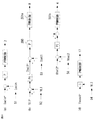
- FIG. 37 is an explanatory diagram of still another switching pattern for realizing the power flow shown in FIGS. 35 and 36. It is explanatory drawing of the control part which implement
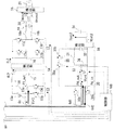
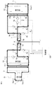
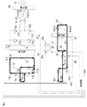
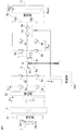
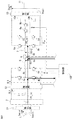
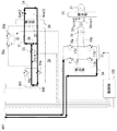
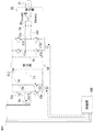
- FIG. 1 and 2 are circuit configuration diagrams of a power conversion device according to Embodiment 1 of the present invention.
- an AC power source 1, a first DC power source 11, and a second DC power source 34 which are a plurality of power supply sources, are connected, and an inverter 17 and a load device are connected. It is connected to a load via the connection end 21.
- the power conversion device according to the first embodiment is applied to, for example, a power supply system centering on a charger of an electric vehicle.
- the AC power source 1 is a commercial AC power source or a private generator
- the first DC power source 11 is a high-voltage battery for vehicle travel
- the second DC power source 34 is a vehicle. It is a lead battery that is a power source for electrical components, and the inverter 17 and the load device connection end 21 can be applied to a system having an AC 100 V power source that can be used in the vehicle.
- the AC power source 1 is connected to the AC / DC converter 2 via the voltage / current detector 51, and the AC voltage Vacin is stored in the capacitor 3 as the DC voltage VL1.
- the DC voltage VL1 is converted into an AC voltage Vtr1 by the first switching circuit 4.
- the first switching circuit 4 is configured as an inverter in which four switch elements 4a to 4d are connected in a bridge shape, and controls the amount of input power received from the AC power supply 1.
- the AC / DC converter 2 described above has a rectifying function for converting the voltage of the AC power supply 1 to DC and a power factor improving function for bringing the input voltage and input current of the AC power supply 1 closer to each other.
- the AC / DC converter 2 corresponds to the power factor conversion circuit in the claims.
- the AC / DC converter 2 may have only a rectifying function for converting the voltage of the AC power supply 1 to DC.
- the AC / DC converter 2 corresponds to the rectifier circuit in the claims.
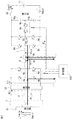
- the first end of the step-up coil 5 is connected to the first AC terminal of the first switching circuit 4, and the second end of the step-up coil 5 is the primary side of a composite winding transformer (hereinafter simply referred to as a transformer) 6.
- the first end of the first winding 6 a is connected, and the second end of the first winding 6 a is connected to the second AC end of the first switching circuit 4.
- the first end of the second winding 6 b that is the secondary side of the transformer 6 is connected to the first end of the booster coil 7, and the second end of the booster coil 7 is the first AC of the second switching circuit 8.
- One end of the second winding 6b is connected to the second end of the second switching circuit 8 and the second end of the second winding 6b is connected to the first end of the switch 9 having two switching elements 9a and 9b.
- the second switching circuit 8 connects the four switch elements 8a to 8d in a bridge type, and functions as a boost chopper when charging the first DC power supply 11.
- the second end of the switch 9 is connected to the connection point between the first ends of the two capacitors 10a and 10b connected in series.
- the DC positive terminal of the second switching circuit 8 is connected to the second end of the capacitor 10a and the voltage.
- the current detection unit 53 is connected to the positive end of the first DC power supply 11.
- the negative DC terminal of the second switching circuit 8 is connected to the negative terminal of the first DC power supply 11 via the second terminal of the capacitor 10 b and the voltage / current detector 53.
- the two capacitors 10a and 10b are configured to have the same capacity here.
- the third winding 6 c on the tertiary side of the transformer 6 has a first end connected to the first end of the booster coil 12, and the second end of the booster coil 12 is the first AC of the third switching circuit 13.
- the second end of the third winding 6 c is connected to the second AC terminal of the third switching circuit 13.
- the third switching circuit 13 includes a series connection of a rectifying element 13a and a switching element 13b and a parallel connection of two legs in which a rectifying element 13c and a switching element 13d are connected in series.
- the third switching circuit 13 normally functions as a rectifier circuit, and functions as a boost chopper when a DC voltage VL2 generated in a smoothing capacitor 15 described later is lower than a predetermined value.
- the AC output voltage Vtr3 generated in the third winding 6c of the transformer 6 is DC-converted by the third switching circuit 13, smoothed by the smoothing coil 14 and the smoothing capacitor 15, and passed through the voltage / current detection unit 54. Is stored in the capacitor 16 and becomes the DC voltage VL2.
- the capacitor 16 is connected to the DC input terminal of the inverter 17 composed of four switch elements 17a to 17d.
- the smoothing coils 18 a and 18 b, the smoothing capacitor 19, the common mode choke coil 20, the voltage / current detector 55, and the load device connection terminal 21 are sequentially connected to the AC output terminal of the inverter 17.
- the load device connection end 21 generates an AC power supply Vacout that is a power supply for various devices (not shown) connected to the load device connection end 21 (hereinafter referred to as an AC load).
- the fourth windings 6d1 and 6d2 serving as the quaternary side of the transformer 6 are configured as a center tap type, and the first ends of the two switch elements 30a and 30b constituting the fourth switching circuit 30 are provided at both ends thereof. Each is connected.
- the first end of the switch element 33 is connected to the connection point that becomes the center tap of the fourth windings 6d1 and 6d2, and the first end of the switch 35 including the two switch elements 35a and 35b is connected. Is done.
- the second end of the switch element 33 is connected to a connection point between the return diode 36 and the first end of the smoothing coil 31.
- the second end of the smoothing coil 31, the second end of the switch 35, and the first end of the smoothing capacitor 32 are connected in common, and are connected to the positive end of the second DC power supply 34 via the voltage / current detector 56.
- the second ends of the switch elements 30 a and 30 b are connected to each other, and are connected to the anode end of the freewheeling diode 36, the second end of the smoothing capacitor 32, and the negative end of the second DC power supply 34.
- the fourth switching circuit 30 includes the two switch elements 30 a and 30 b, the switch element 33, the return diode 36, and the smoothing coil 31.
- the fourth switching circuit 30 is stepped down by the configuration of the switch element 33, the return diode 36, and the smoothing coil 31. Functions as a chopper.
- the second switching circuit 8 and the fourth switching circuit 30 are referred to as a second switching circuit connected to a DC power supply in the claims.
- the switch elements constituting the first to fourth switching circuits 4, 8, 13, 30 and the switch elements constituting the inverter 17 are not limited to IGBTs (Insulated Gate Bipolar Transistors), but are MOSFETs (Metal Oxides). (Semiconductor Field Effect Transistor) or the like. Further, the control unit 100 plays a role of controlling the operations of the first to fourth switching circuits 4, 8, 13, 30 and the inverter 17.
- the power supply from the AC power source 1 is insufficient, so the AC power source 1 and the first DC power source 11 are connected.
- the supply power P1_in from the AC power supply 1 and the supply power P2_in from the first DC power supply 11 are the supply power P3_out to the AC load connected to the load device connection end 21, and The power is distributed to the supply power P4_out to the second DC power supply 34.
- the AC power source 1 and the first DC power source 11 are power supply sources, and the AC load and the second DC power source 34 connected to the load device connection end 21 are loads.
- the power supply from the AC power source 1 is insufficient, and the charge amount of the first DC power source 11 is insufficient. Therefore, when both the AC power supply 1 and the second DC power supply 34 are used as power supply sources, the supply power P1_in from the AC power supply 1 and the supply power P4_in from the second DC power supply 34 are the load device connection ends.
- the power supply P3_out supplied to the AC load connected to the power supply 21 and the power supply P2_out supplied to the first DC power supply 11 are distributed.
- the AC power source 1 and the second DC power source 34 are power supply sources, and the AC load connected to the load device connection end 21 and the first DC power source 11 are loads.
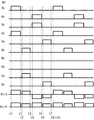
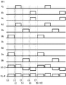
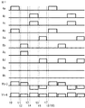
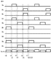
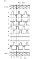
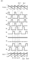
- FIG. 7 shows a switching pattern when the first DC power supply 11 is discharged by causing the second switching circuit 8 to perform a half-bridge operation.
- FIG. 7 shows the switch elements 4a to 4d of the first switching circuit 4, the switch elements 8a to 8d of the second switching circuit 8, the gate signals of the switch elements 9a and 9b constituting the switch 9, and the transformer on the load side.
- 6 shows an output voltage Vtr3 of the sixth third winding 6c and a voltage Vtr4 after rectification of the output voltages of the fourth windings 6d1 and 6d2 of the transformer 6 on the load side.
- 8 to 15 show current flows generated by the switching pattern of FIG. In these cases, the AC power supply 1 is premised on the operation in the positive half-wave state, but the same operation is performed in the negative half-wave state.
- An output voltage Vtr3 determined by the voltage VL1 of the capacitor 3 and the turn ratio of the first winding 6a and the third winding 6c is applied to the third winding 6c of the transformer 6 as indicated by an arrow in FIG.
- the electric power is supplied to the load device connected to the load device connection end 21 via the smoothing capacitor 15 and the inverter 17.
- the output voltage determined by the voltage VL1 of the capacitor 3 and the turn ratio of the first winding 6a and the fourth winding 6d1, 6d2 is applied to the fourth winding 6d1, 6d2 of the transformer 6,
- the rectified voltage Vtr4 is supplied to the second DC power supply 34 via the switch element 33, the freewheeling diode 36, and the reactor 31.
- the second winding 6b of the transformer 6 has an output voltage Vtr2 determined by the voltage VL1 of the capacitor 3 and the turn ratio of the first winding 6a and the second winding 6b as shown by an arrow in FIG. Applied upwards as shown.
- Vtr2 the output voltage
- the second switching circuit 8 operates as a rectifier as shown in FIG.
- the current flow of the second switching circuit 8 as shown in FIG. 8 does not occur.
- An output voltage Vtr3 determined by the voltage of the capacitor 10b and the turn ratio of the second winding 6b and the third winding 6c is applied to the third winding 6c of the transformer 6 as indicated by an arrow in FIG. Is supplied to the load device connected to the load device connection end 21 via the smoothing capacitor 15 and the inverter 17. Further, an output voltage determined by the voltage of the capacitor 10b and the turn ratio of the second winding 6b and the fourth windings 6d1 and 6d2 is applied to the fourth windings 6d1 and 6d2 of the transformer 6.
- the rectified voltage Vtr4 is supplied with electric power to the second DC power supply 34 via the switch element 33, the freewheeling diode 36, and the reactor 31.
- an output voltage Vtr1 determined by the voltage of the capacitor 10b and the turn ratio of the second winding 6b and the first winding 6a is indicated by an arrow in FIG. Applied upward.
- the first switching circuit 4 operates as a rectifier as shown in FIG.
- the voltage VL1 of the capacitor 3 is higher than the output voltage Vtr1
- the current flow of the first switching circuit 4 as shown in FIG. 10 does not occur.
- the output voltage Vtr3 determined by the voltage VL1 of the capacitor 3 and the turn ratio of the first winding 6a and the third winding 6c is downward as shown by the arrow in FIG. Is supplied to the load device connected to the load device connection end 21 via the smoothing capacitor 15 and the inverter 17.
- the output voltage determined by the voltage VL1 of the capacitor 3 and the turn ratio of the first winding 6a and the fourth winding 6d1, 6d2 is applied to the fourth winding 6d1, 6d2 of the transformer 6,
- the rectified voltage Vtr4 is supplied to the second DC power supply 34 via the switch element 33, the freewheeling diode 36, and the reactor 31.
- the second winding 6b of the transformer 6 has an output voltage Vtr2 determined by the voltage VL1 of the capacitor 3 and the turn ratio of the first winding 6a and the second winding 6b as shown by an arrow in FIG. Applied downward as shown.
- Vtr2 the second switching circuit 8 operates as a rectifier as shown in FIG.
- the current flow of the second switching circuit 8 as shown in FIG. 12 does not occur.
- the third winding 6c of the transformer 6 has an output voltage Vtr3 determined by the voltage of the capacitor 10a and the turn ratio of the second winding 6b and the third winding 6c in the downward direction indicated by the arrow in FIG. Power is supplied to the load device connected to the load device connection end 21 via the smoothing capacitor 15 and the inverter 17. Also, the fourth winding 6d1, 6d2 of the transformer 6 is applied with an output voltage determined by the voltage of the capacitor 10a and the turn ratio of the second winding 6b and the fourth winding 6d1, 6d2.
- the rectified voltage Vtr4 is supplied with electric power to the second DC power supply 34 via the switch element 33, the freewheeling diode 36, and the reactor 31.
- the output voltage Vtr1 determined by the voltage of the capacitor 10a and the turn ratio of the second winding 6b and the first winding 6a is indicated by an arrow in FIG. Applied downward.
- the first switching circuit 4 operates as a rectifier as shown in FIG.
- the switch elements 4a and 4d of the first switching circuit 4 are simultaneously turned on, as at time t0.
- the minimum repetition period in which power is alternately supplied from the AC power supply 1 and the first DC power supply 11 in a time-sharing manner is defined as one switching period. That is, in the switching pattern shown in FIG. 7, each period from time t0 to t4 and time t4 to t8 is defined as one switching period. In this case, power is supplied toward the transformer 6 with positive and negative polarities every one switching period, and both the first switching circuit 4 and the second switching circuit 8 are alternately switched within one switching period. Electric power is supplied in the division. For this reason, as shown in FIGS. 8 to 15, in any state, power is supplied to the load while maintaining the current continuity from the AC power supply 1 and the first DC power supply 11.
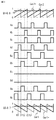
- FIG. 7 or FIG. 17 shows a switching pattern in the case where the first DC power supply 11 is discharged by causing the second switching circuit 8 to perform a full bridge operation.
- FIG. 17 shows gate signals of the switch elements 4a to 4d of the first switching circuit 4, gate signals of the switch elements 8a to 8d of the second switching circuit 8, and gate signals of the switch elements 9a and 9b constituting the switch 9.
- the output voltage Vtr3 of the third winding 6c of the transformer 6 on the load side and the voltage Vtr4 after rectification of the output voltage of the fourth windings 6d1 and 6d2 of the transformer 6 on the load side are respectively shown.
- 18 to 25 show current flows generated by the switching pattern of FIG. In these cases, the AC power supply 1 is premised on the operation in the positive half-wave state, but the same operation is performed in the negative half-wave state.
- FIG. 17 power is supplied from the AC power supply 1 during the period from time t0 to time t1. That is, the switch elements 4a and 4d of the first switching circuit 4 are simultaneously turned on at time t0, and the on state is maintained until time t1. The current flow during this period is shown in FIGS.
- the output voltage Vtr3 determined by the voltage VL1 of the capacitor 3 and the turns ratio of the first winding 6a and the third winding 6c is indicated by an arrow in FIG.
- the electric power is supplied to the load device connected to the load device connection end 21 via the smoothing capacitor 15 and the inverter 17.
- the output voltage determined by the voltage VL1 of the capacitor 3 and the turn ratio of the first winding 6a and the fourth winding 6d1, 6d2 is applied to the fourth winding 6d1, 6d2 of the transformer 6,
- the rectified voltage Vtr4 is supplied to the second DC power supply 34 via the switch element 33, the freewheeling diode 36, and the reactor 31.
- the second winding 6b of the transformer 6 has an output voltage Vtr2 determined by the voltage VL1 of the capacitor 3 and the turns ratio of the first winding 6a and the second winding 6b as shown by an arrow in FIG. Applied upwards as shown.
- Vtr2 the output voltage
- the second switching circuit 8 operates as a rectifier as shown in FIG.
- the current flow of the second switching circuit 8 shown in FIG. 18 does not occur.
- FIG. 17 power is supplied from the first DC power supply 11 during the period from time t2 to time t3. That is, the switch elements 8b and 8c of the second switching circuit 8 are simultaneously turned on at time t2, and the on state is maintained until time t3.
- the current flow during this period is shown in FIGS.
- the output voltage Vtr3 determined by the total voltage of the capacitors 10a and 10b and the turn ratio of the second winding 6b and the third winding 6c is indicated by an arrow in FIG. Electric power is supplied to the load device connected to the load device connection end 21 via the smoothing capacitor 15 and the inverter 17.
- the voltage determined by the total voltage of the capacitors 10a and 10b and the turn ratio of the second winding 6b and the fourth winding 6d1 and 6d2 is applied to the fourth windings 6d1 and 6d2 of the transformer 6.
- the rectified voltage Vtr4 is supplied to the second DC power supply 34 via the switch element 33, the freewheeling diode 36, and the reactor 31.
- the output voltage Vtr1 determined by the total voltage of the capacitors 10a and 10b and the turn ratio of the second winding 6b and the first winding 6a is applied to the first winding 6a of the transformer 6 in FIG. Applied upward as indicated by the arrow.
- the first switching circuit 4 operates as a rectifier as shown in FIG.
- the voltage VL1 of the capacitor 3 is higher than the output voltage Vtr1
- the current flow of the first switching circuit 4 as shown in FIG. 20 does not occur.
- FIG. 17 power is supplied from the AC power supply 1 during the period from time t4 to time t5. That is, the switch elements 4b and 4c of the first switching circuit 4 are simultaneously turned on at time t4, and the on state is maintained until time t5.
- the current flow during this period is shown in FIGS.
- the third winding 6c of the transformer 6 has an output voltage Vtr3 determined by the voltage VL1 of the capacitor 3 and the turn ratio of the first winding 6a and the third winding 6c, and is directed downward as indicated by an arrow in FIG. Is supplied to the load device connected to the load device connection end 21 via the smoothing capacitor 15 and the inverter 17.
- the output voltage determined by the voltage VL1 of the capacitor 3 and the turn ratio of the first winding 6a and the fourth winding 6d1, 6d2 is applied to the fourth winding 6d1, 6d2 of the transformer 6,
- the rectified voltage Vtr4 is supplied to the second DC power supply 34 via the switch element 33, the freewheeling diode 36, and the reactor 31.
- the second winding 6b of the transformer 6 has an output voltage Vtr2 determined by the voltage VL1 of the capacitor 3 and the turn ratio of the first winding 6a and the second winding 6b as shown by an arrow in FIG. Applied downward as shown.
- Vtr2 the second switching circuit 8 operates as a rectifier as shown in FIG.
- the current flow of the second switching circuit 8 as shown in FIG. 22 does not occur.
- FIG. 17 power is supplied from the first DC power supply 11 during the period from time t6 to time t7. That is, the switch elements 8a and 8d of the second switching circuit 8 are simultaneously turned on at time t6, and the on state is maintained until time t7.
- the current flow during this period is shown in FIGS.
- the output voltage Vtr3 determined by the total voltage of the capacitors 10a and 10b and the turn ratio of the second winding 6b and the third winding 6c is indicated by an arrow in FIG.
- the electric power is supplied to the load device connected to the load device connection end 21 via the smoothing capacitor 15 and the inverter 17. Further, an output voltage determined by the total voltage of the capacitors 10a and 10b and the turn ratio of the second winding 6b and the fourth windings 6d1 and 6d2 is applied to the fourth windings 6d1 and 6d2 of the transformer 6.
- the rectified voltage Vtr4 is supplied to the second DC power supply 34 via the switch element 33, the freewheeling diode 36, and the reactor 31.
- the output voltage Vtr1 determined by the total voltage of the capacitors 10a and 10b and the turn ratio of the second winding 6b and the first winding 6a is applied to the first winding 6a of the transformer 6 as shown in FIG. Applied downward as indicated by the arrow.
- the first switching circuit 4 operates as a rectifier as shown in FIG.
- the switch elements 4a and 4d of the first switching circuit 4 are simultaneously turned on, as at time t0.
- the minimum repetition period during which power is alternately supplied from the AC power supply 1 and the first DC power supply 11 in a time-sharing manner is defined as the switching period.
- each period from time t0 to t4 and time t4 to t8 in FIG. 17 is defined as one switching period.
- power is supplied to the transformer 6 with both positive and negative polarities, and within one switching period, both the first switching circuit 4 and the second switching circuit 8 are alternately time-shared. Power is supplied. For this reason, as shown in FIGS. 18 to 25, it is possible to realize power supply to the load while maintaining current continuity from the AC power supply 1 and the first DC power supply 11 in any state.
- the AC power source 1 passes through the AC / DC converter 2 and the first switching circuit 4 during one switching period with respect to the transformer 6. Since the power supply and the power supply from the first DC power supply 11 via the second switching circuit 8 are performed in a time-sharing manner, the AC power supply 1 and the first DC power supply 11 are connected to the load device connection end 21. In addition, it is possible to supply power to the load equipment and the second DC power supply 34 while maintaining current continuity.
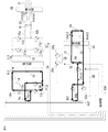
- FIGS. 7, 16, 17, and 26 The block diagram of the power distribution control of the control unit 100 that executes the above switching pattern (FIGS. 7, 16, 17, and 26) is one of FIGS.
- the difference in control based on FIGS. 27 to 32 is as follows.
- the total on-time of the first switching circuit 4 and the second switching circuit 8 is constant, and the on-time of the first switching circuit 4 and the on-time of the second switching circuit 8 are constant.
- the voltage VL1 of the capacitor 3 is controlled at a rate of time.
- the total ON time of the first switching circuit 4 and the second switching circuit 8 is obtained from the constant voltage control system of the second DC power supply 34, so that the total The voltage Vbat2 of the second DC power supply 34 is controlled to be constant during the on time, and the voltage VL1 of the capacitor 3 is controlled at the ratio of each on time.
- the total on-time of the first switching circuit 4 and the second switching circuit 8 is obtained from the constant voltage control system of the smoothing capacitor 15, so that the total on-time is obtained.
- the voltage VL2 of the smoothing capacitor 15 is controlled to be constant, and the voltage VL1 of the capacitor 3 is controlled at each on-time ratio. Details of the control in FIGS. 27 to 32 will be described below.
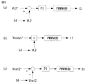
- the control unit 100 performs proportional control (P control) on the deviation between the current command value Iacin * of the AC power supply 1 and the current detection value Iacin of the voltage / current detection unit 51 for the AC / DC converter 2.
- P control proportional control
- the power is supplied to the capacitor 3 with a constant current by PWM control.
- the AC current is controlled to a high power factor.
- the current command value Iacin * of the AC power supply 1 may be arbitrarily set (FIG. 27 (a)).
- control unit 100 performs proportional-integral control (PI control) on the deviation between the voltage command value VL1 * of the capacitor 3 and the voltage detection value VL1 of the voltage / current detection unit 52 with respect to the second switching circuit 8.
- PI control proportional-integral control
- the charging current command value Ibat1 * of the DC power supply 11 is calculated.
- the deviation between the charging current command value Ibat1 * of the first DC power supply 11 and the current detection value Ibat1 of the voltage / current detector 53 is proportionally controlled (P control), and the second switching circuit 8 is controlled by PWM control. Make it work.
- the control unit 100 operates the first switching circuit 4 by calculating the difference between the output of the proportional control (P control) and the reference duty Dref and performing PWM control.
- the voltage VL1 of the capacitor 3 is controlled at a constant voltage (FIG. 27B).
- control unit 100 performs proportional-integral control (PI control) on the deviation between the voltage command value VL2 * of the smoothing capacitor 15 and the voltage detection value VL2 of the voltage / current detection unit 54 for the third switching circuit 13, and performs PWM control.
- PI control proportional-integral control
- control unit 100 uses the quotient of the command value Vacout * of the output AC voltage and the voltage detection value VL2 of the voltage / current detection unit 56 for the inverter 17 as the modulation factor of the sine wave inverter, and the AC voltage Vacout is applied to the load device by PWM control.
- the data is output to the connection end 21 (FIG. 28 (b)).
- control unit 100 performs the following control for the step-down chopper circuit that is a switching circuit between the second DC power supply 34 and the transformer 6.
- the deviation between the voltage command value Vbat2 * of the second DC power supply 34 and the voltage detection value Vbat2 of the voltage / current detector 56 is proportional-integral-controlled (PI control), and the switch 33 is driven by PWM control to drive the switch 33.
- the charging voltage control of the second DC power supply 34 is performed (FIG. 28C).
- the ratio between the power supply P ⁇ b> 1 from the AC power supply 1 and the power supply P ⁇ b> 2 from the first DC power supply 11 is arbitrarily controlled. Can do.
- the total on-time of the first switching circuit 4 and the second switching circuit 8 is made constant, and the voltage VL1 of the capacitor 3 is controlled at the ratio of each on-time.
- the total ON time of the first switching circuit 4 and the second switching circuit 8 is defined by the reference duty Dref and can be arbitrarily set.
- the control unit 100 proportionally controls the deviation between the current command value Iacin * of the AC power supply 1 and the current detection value Iacin of the voltage / current detection unit 51 for the AC / DC converter 2. And power is supplied to the capacitor 3 with a constant current by PWM control. At the same time, the AC current is controlled to a high power factor. At this time, the current command value Iacin * of the AC power supply 1 may be arbitrarily set (FIG. 29 (a)).
- control unit 100 performs proportional-integral control (PI control) on the deviation between the voltage command value VL1 * of the capacitor 3 and the voltage detection value VL1 of the voltage / current detection unit 52 with respect to the second switching circuit 8.
- PI control proportional-integral control
- the charging current command value Ibat1 * of the DC power supply 11 is calculated.
- P control proportionally controlled
- the second switching circuit 8 is controlled by PWM control. Make it work.
- the control unit 100 performs proportional-integral control (PI control) on the deviation between the voltage command value Vbat2 * of the second DC power supply 34 and the voltage detection value Vbat2 of the voltage / current detection unit 56. Then, the first switching circuit 4 is operated by calculating a deviation between the output of the PI control and the output of the P control calculated above and performing PWM control.
- PI control proportional-integral control
- the voltage Vbat2 of the second DC power supply 34 is controlled with a constant voltage while controlling the voltage VL1 of the capacitor 3 with a constant voltage (FIG. 29B).
- control unit 100 performs proportional-integral control (PI control) on the deviation between the voltage command value VL2 * of the smoothing capacitor 15 and the voltage detection value VL2 of the voltage / current detection unit 54 for the third switching circuit 13, and performs PWM control.
- PI control proportional-integral control
- control unit 100 uses the quotient of the command value Vacout * of the output AC voltage and the voltage detection value VL2 of the voltage / current detection unit 56 for the inverter 17 as the modulation factor of the sine wave inverter, and the AC voltage Vacout is applied to the load device by PWM control. Output to the connection end 21 (FIG. 30B).
- the ratio of the supplied power P1 from the AC power supply 1 and the supplied power P2 from the first DC power supply 11 can be arbitrarily controlled. it can.
- the total ON time of the first switching circuit 4 and the second switching circuit 8 is obtained from the constant voltage control system of the second DC power supply 34, so that the second DC power supply can be obtained with the total ON time.
- the voltage Vbat2 of 34 is controlled to be constant, and the voltage VL1 of the capacitor 3 is controlled by the ratio of the on-time of the first switching circuit 4 and the on-time of the second switching circuit 8.
- the control unit 100 proportionally controls the deviation between the current command value Iacin * of the AC power supply 1 and the current detection value Iacin of the voltage / current detection unit 51 for the AC / DC converter 2. And power is supplied to the capacitor 3 with a constant current by PWM control. At the same time, the AC current is controlled to a high power factor. At this time, the current command value Iacin * of the AC power supply 1 may be arbitrarily set (FIG. 31 (a)).
- control unit 100 performs proportional-integral control (PI control) on the deviation between the voltage command value VL1 * of the capacitor 3 and the voltage detection value VL1 of the voltage / current detection unit 52 with respect to the second switching circuit 8.
- PI control proportional-integral control
- the charging current command value Ibat1 * of the DC power supply 11 is calculated.
- P control proportionally controlled
- the second switching circuit 8 is controlled by PWM control. Make it work.
- the control unit 100 performs proportional-integral control (PI control) on the deviation between the voltage command value VL2 * of the smoothing capacitor 15 and the voltage detection value VL2 of the voltage / current detection unit 54. Then, the first switching circuit 4 is operated by calculating a deviation between the output of the PI control and the output of the P control calculated above and performing PWM control.
- PI control proportional-integral control
- the voltage VL2 of the smoothing capacitor 15 is controlled to be constant while controlling the voltage VL1 of the capacitor 3 with a constant voltage (FIG. 31 (b)).
- control unit 100 uses the quotient of the command value Vacout * of the output AC voltage and the voltage detection value VL2 of the voltage / current detection unit 56 for the inverter 17 as the modulation factor of the sine wave inverter, and the AC voltage Vacout is applied to the load device by PWM control.
- the data is output to the connection end 21 (FIG. 32 (a)).
- the control unit 100 controls the step-down chopper circuit that is a switching circuit between the second DC power supply 34 and the transformer 6 as follows.
- the deviation between the voltage command value Vbat2 * of the second DC power supply 34 and the voltage detection value Vbat2 of the voltage / current detector 56 is proportional-integral-controlled (PI control), and the switch 33 is driven by PWM control to drive the switch 33.
- the charging voltage control of the second DC power supply 34 is performed (FIG. 32B).
- the ratio of the supplied power P1 from the AC power supply 1 and the supplied power P2 from the first DC power supply 11 can be arbitrarily controlled.
- the total on-time of the first switching circuit 4 and the second switching circuit 8 is obtained from the constant voltage control system of the smoothing capacitor 15, so that the voltage VL2 of the smoothing capacitor 15 is constant with the total on-time.
- the voltage VL1 of the capacitor 3 is controlled by the ratio of the ON time of the first switching circuit 4 and the ON time of the second switching circuit 8.
- the first DC power source 11 performs constant current charging control and the second DC power source 34 performs constant voltage charging control.
- 11 and the second DC power source 34 can be charged by any method, and therefore, an appropriate charging method corresponding to the DC power source can be adopted.
- the first DC power supply 11 may be charged with a constant voltage
- the second DC power supply 34 may be charged with a constant current.
- the voltage of the capacitor 3 is always controlled in the power flow for discharging the first DC power supply 11 in a state where the AC power supply 1 is not connected. Therefore, the voltage rise protection of the capacitor 3 can be performed.
- the utilization rate of the AC power supply 1 is dramatically improved. That is, when the above power distribution is performed, when the power consumption of any of the loads increases and the power consumption of the load cannot be covered only by the input power of the AC power supply 1, the power input from the AC power supply 1 is maintained.
- the first DC power supply 11 supplies only the difference power between the power consumption of the load and the input power of the AC power supply 1. By doing so, the input power from the AC power supply 1 can be utilized to the maximum while the discharge of the power charged in the first DC power supply 11 is minimized. Therefore, power saving can be realized as compared with the case where only the power of the first DC power supply 11 charged from the AC power supply 1 is used.
- the power supply from the AC power source 1 through the AC / DC converter 2 and the first switching circuit 4 and the first DC power source 11 to the second switching circuit 8 are switched during one switching period.
- a case has been described in which power supply is performed in a time-sharing manner.
- the present invention is not limited to this, and as shown in FIGS. 5 and 6, the power supply from the AC power source 1 through the AC / DC converter 2 and the first switching circuit 4 and the second DC power source during one switching period. It is also possible to perform power supply from 34 through the fourth switching circuit 30 in a time-sharing manner.
- the switch 33 operates so as to make the voltage VL1 of the capacitor 3 constant, and the second switching circuit 8 is controlled so as to make the voltage or current of the first DC power supply 11 constant.
- constant input power P1_in is received from the AC power supply 1, and supply power P3_out having the AC voltage Vacout and charging power P2_out for the first DC power supply 11 are obtained only by this input power P1_in.
- the operation is performed such that the insufficient power is supplied from the second DC power supply 34 (supplied power P4_in).
- all of the AC power source 1, the first DC power source 11, and the second DC power source 34 can be used as the power source. In that case, it can be realized by increasing the number of time divisions within one switching period. Furthermore, even when a plurality of power supplies are connected, the same effect can be realized by dividing one switching period according to the number of power supplies to be transmitted.
- the AC power source 1 and the AC / DC converter 2 described above can be replaced with a DC voltage source. In this case, by providing a reactor between the replaced DC voltage source and the capacitor 3, the same effect as the above control can be obtained.
- the first switching circuit 4 connected to the DC voltage source is the second switching connected to the DC power supply in the claims. It is called a circuit.
- the second switching circuit 8 is configured to bridge the switch elements 8a to 8d that can transmit power in both directions and includes a switch element and a diode reversely parallel to the switch element.
- the amount of charge to the first DC power supply 11 cannot be controlled because the current is rectified by a diode connected in a bridge form. Therefore, in the present embodiment, when the step-up coil 7 is provided between the second winding 6b and the second switching circuit 8 and the first DC power supply 11 is charged, the second winding of the transformer 6 is used.
- the output voltage of 6b is set lower than the voltage of the first DC power supply 11, and the second switching circuit 8 is made to function as a boost chopper.
- the second switching circuit connected to the DC power source when the second switching circuit connected to the DC power source is capable of transmitting power in both directions and is configured with a bridge using a switch element and a diode antiparallel to the switch element,
- the second switching circuit may have a boosting function when power is transmitted from the second switching circuit to the DC power source.
- the second switching circuit connected to the DC power source is capable of transmitting power in both directions and has a bridge configuration using a switch element and a diode reversely parallel to the switch element
- the second switching circuit The DC / DC converter includes a DC / DC converter between the second switching circuit and the DC power source instead of having the function of boosting the switching circuit, and transmits power from the second switching circuit to the DC power source. Thus, charging to the DC power supply may be stopped.
- a part of the fourth switching circuit 30 is configured as a center tap type with the fourth windings 6d1 and 6d2 of the transformer 6, and a rectifier circuit is configured by connecting switch elements 30a and 30b to both ends thereof. is doing.
- a part of the fourth switching circuit 30 includes a switch element 33, a return diode 36, and a smoothing coil 31, thereby constituting a step-down chopper, that is, a DC / DC converter. That is, as described in claim 8 of the claims, the fourth switching circuit 30 has a function of rectifying the voltage generated in the winding of the transformer and controlling the voltage or current.
- the fourth switching circuit 30 is a rectifier circuit.
- Claims 7 and 8 are described in terms of the second DC power supply 34 as a load device. As described above, the second DC power supply 34 is used as a power supply source as a load. It also has the function of supplying power to the side.
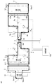
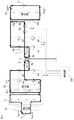
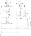
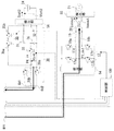
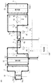
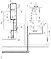
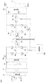
- FIG. 33 and 34 are circuit configuration diagrams of the power conversion device according to the second embodiment of the present invention. Components corresponding to or corresponding to those of the first embodiment shown in FIGS. 1 and 2 are denoted by the same reference numerals. .
- a structural feature of the second embodiment is that it is constituted by four switch elements 17a to 17dc on the output end side of the AC / DC converter 2 via the voltage / current detector 54 in parallel with the first switching circuit 4.
- the DC input terminal of the inverter 17 is connected.
- smoothing coils 18 a and 18 b, a smoothing capacitor 19, a common mode choke coil 20, a voltage / current detection unit 55, and a load device connection terminal 21 are sequentially connected to the AC output terminal of the inverter 17. Then, an AC voltage Vacout of an AC load (not shown) is generated at the load device connection end 21.
- the AC power source 1 and the first DC power source 11 are connected.
- the supply power P1_in from the AC power supply 1 and the supply power P2_in from the first DC power supply 11 are the supply power P3_out to the AC load connected to the load device connection end 21, and It is distributed to the charging power P4_out for the second DC power supply 34.
- the power supply from the AC power source 1 is insufficient, and the charge amount of the first DC power source 11 is insufficient. Therefore, when both the AC power supply 1 and the second DC power supply 34 are supplied with power, the supply power P1_in from the AC power supply 1 and the supply power P4_in from the second DC power supply 34 are the first DC.
- the charging power P2_out of the power source 11 and the power P3_out supplied to the AC load connected to the load device connection end 21 are distributed.
- FIGS. 35 and 36 that is, a switching pattern for realizing power supply using both the AC power supply 1 and the first DC power supply 11 as power supply sources will be described below.
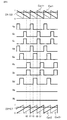
- the power flow in this case can be realized by the switching pattern of FIG. FIG. 39 shows a switching pattern in the case where the first DC power supply 11 is discharged by causing the second switching circuit 8 to perform a half-bridge operation.
- An output voltage determined by the voltage VL1 of the capacitor 3 and the turn ratio of the first winding 6a and the fourth windings 6d1 and 6d2 is applied to the fourth windings 6d1 and 6d2 of the transformer 6, and the rectification thereof is performed.
- the latter voltage Vtr4 is supplied with electric power to the second DC power supply 34 via the switch element 33, the freewheeling diode 36, and the reactor 31. Further, power is supplied to the load device connected to the load device connection end 21 via the inverter 17.
- the second winding 6b of the transformer 6 has an output voltage Vtr2 determined by the voltage VL1 of the capacitor 3 and the turn ratio of the first winding 6a and the second winding 6b as shown by an arrow in FIG.
- the second switching circuit 8 operates as a rectifier as shown in FIG.
- the current flow of the second switching circuit 8 shown in FIG. 40 does not occur.
- FIG. 39 power is supplied from the first DC power supply 11 during the period from time t2 to time t3. That is, at time t2, the switch element 8b of the second switching circuit 8 and the switch element 9a of the switch 9 are simultaneously turned on, and remain on until time t3. The current flow during this period is shown in FIGS.
- An output voltage determined by the voltage of the capacitor 10b and the turn ratio of the second winding 6b and the fourth windings 6d1 and 6d2 is applied to the fourth windings 6d1 and 6d2 of the transformer 6. Is supplied to the second DC power supply 34 via the switch element 33, the freewheeling diode 36, and the reactor 31. Further, power is supplied to the load device connected to the load device connection end 21 via the inverter 17. Furthermore, the first winding 6a of the transformer 6 has an output voltage Vtr1 determined by the voltage of the capacitor 10b and the turn ratio of the second winding 6b and the first winding 6a as indicated by an arrow in FIG. Applied upward.
- the first switching circuit 4 operates as a rectifier as shown in FIG.
- the voltage VL1 of the capacitor 3 is lower than the output voltage Vtr1
- the current flow of the first switching circuit 4 shown in FIG. 42 does not occur.
- FIG. 39 power is supplied from the AC power supply 1 during the period from time t4 to time t5. That is, the switch elements 4b and 4c of the first switching circuit 4 are simultaneously turned on at time t4, and the on state is maintained until time t5.
- the current flow during this period is shown in FIGS.
- An output voltage determined by the voltage VL1 of the capacitor 3 and the turn ratio of the first winding 6a and the fourth windings 6d1 and 6d2 is applied to the fourth windings 6d1 and 6d2 of the transformer 6, and the rectification thereof is performed.
- the latter voltage Vtr4 is supplied with electric power to the second DC power supply 34 via the switch element 33, the freewheeling diode 36, and the reactor 31. Further, power is supplied to the load device connected to the load device connection end 21 via the inverter 17.
- the second winding 6b of the transformer 6 has an output voltage Vtr2 determined by the voltage VL1 of the capacitor 3 and the turn ratio of the first winding 6a and the second winding 6b as shown by an arrow in FIG. Applied downward as shown.
- the second switching circuit 8 operates as a rectifier as shown in FIG.
- the current flow of the second switching circuit 8 shown in FIG. 44 does not occur.
- FIG. 39 power is supplied from the first DC power supply 11 during the period from time t6 to time t7. That is, at time t6, the switch element 8a of the second switching circuit 8 and the switch element 9b of the switch 9 are simultaneously turned on, and remain on until time t7. The current flow during this period is shown in FIGS.
- An output voltage determined by the voltage of the capacitor 10a and the turn ratio of the second winding 6b and the fourth winding 6d1, 6d2 is applied to the fourth windings 6d1, 6d2 of the transformer 6, and after the rectification Is supplied to the second DC power supply 34 via the switch element 33, the freewheeling diode 36, and the reactor 31. Further, power is supplied to the load device connected to the load device connection end 21 via the inverter 17. Further, the voltage of the capacitor 10a and the output voltage Vtr1 determined by the turn ratio of the second winding 6b and the first winding 6a are applied to the first winding 6a of the transformer 6 downward as indicated by the arrow in FIG. To be applied.
- the first switching circuit 4 operates as a rectifier as shown in FIG.
- the voltage VL1 of the capacitor 3 is lower than the output voltage Vtr1
- the current flow of the first switching circuit 4 shown in FIG. 46 does not occur.
- the switch elements 4a and 4d of the first switching circuit 4 are simultaneously turned on, as at time t0.
- a minimum repetition period in which power is alternately supplied from the AC power supply 1 and the first DC power supply 11 in a time-sharing manner is defined as one switching period. That is, if each period from time t0 to t4 and time t4 to t8 in FIG. 39 is defined as one switching period, power is supplied to the transformer 6 with both positive and negative polarities for each switching period, and one switching is performed. Within the period, power is supplied alternately from both the first switching circuit 4 and the second switching circuit 8 in a time division manner. Therefore, as shown in FIGS. 40 to 47, power supply to the load device can be realized while maintaining the current continuity from the AC power supply 1 and the first DC power supply 11 in any state.
- both switch elements 9a and 9b constituting the switch 9 may operate in synchronization with the switching of the switch elements 8a and 8b of the second switching circuit 8. Absent.
- FIG. 35 and 36 that is, a switching pattern for realizing power supply using both the AC power supply 1 and the first DC power supply 11 as power supply sources is the switching pattern of FIG.
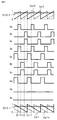
- the switching pattern shown in FIG. FIG. 49 shows a switching pattern in the case where the first DC power supply 11 is discharged by causing the second switching circuit 8 to perform a full bridge operation.
- the fourth windings 6d1 and 6d2 of the transformer 6 are applied with the voltage VL1 of the capacitor 3 and an output voltage determined by the turn ratio of the first winding 6a and the fourth windings 6d1 and 6d2, and after the rectification Is supplied to the second DC power supply 34 via the switch element 33, the freewheeling diode 36, and the reactor 31. Further, power is supplied to the load device connected to the load device connection end 21 via the inverter 17. Furthermore, the second winding 6b of the transformer 6 has an output voltage Vtr2 determined by the voltage VL1 of the capacitor 3 and the turn ratio of the first winding 6a and the second winding 6b as indicated by an arrow in FIG. Applied upward.
- the second switching circuit 8 operates as a rectifier as shown in FIG.
- the current flow of the second switching circuit 8 shown in FIG. 50 does not occur.
- a voltage determined by the total voltage of the capacitors 10a and 10b and the turn ratio of the second winding 6b and the fourth windings 6d1 and 6d2 is applied to the fourth windings 6d1 and 6d2 of the transformer 6.
- the rectified voltage Vtr4 is supplied with electric power to the second DC power supply 34 via the switch element 33, the freewheeling diode 36, and the reactor 31. Further, power is supplied to the load device connected to the load device connection end 21 via the inverter 17. Further, the output voltage Vtr1 determined by the total voltage of the capacitors 10a and 10b and the turn ratio of the second winding 6b and the first winding 6a is applied to the first winding 6a of the transformer 6 as shown in FIG. Applied upward as indicated by an arrow.
- the first switching circuit 4 operates as a rectifier as shown in FIG.
- the voltage VL1 of the capacitor 3 is lower than the output voltage Vtr1
- the current flow of the first switching circuit 4 shown in FIG. 52 does not occur.
- FIG. 49 power is supplied from the AC power supply 1 during the period from time t4 to time t5. That is, the switch elements 4b and 4c of the first switching circuit 4 are simultaneously turned on at time t4, and the on state is maintained until time t5.
- the current flow during this period is shown in FIGS.
- the voltage determined by the voltage VL1 of the capacitor 3 and the turn ratio of the first winding 6a and the fourth winding 6d1, 6d2 is applied to the fourth windings 6d1, 6d2 of the transformer 6, and after the rectification Is supplied to the second DC power supply 34 via the switch element 33, the freewheeling diode 36, and the reactor 31. Further, power is supplied to the load device connected to the load device connection end 21 via the inverter 17. Further, the second winding 6b of the transformer 6 has an output voltage Vtr2 determined by the voltage VL1 of the capacitor 3 and the turn ratio of the first winding 6a and the second winding 6b as shown by an arrow in FIG. Applied downward as shown.
- the second switching circuit 8 operates as a rectifier as shown in FIG.
- the current flow of the second switching circuit 8 shown in FIG. 54 does not occur.
- An output voltage determined by the total voltage of the capacitors 10a and 10b and the turn ratio of the second winding 6b and the fourth windings 6d1 and 6d2 is applied to the fourth windings 6d1 and 6d2 of the transformer 6.
- the rectified voltage Vtr4 is supplied to the second DC power supply 34 via the switch element 33, the freewheeling diode 36, and the reactor 31. Further, power is supplied to the load device connected to the load device connection end 21 via the inverter 17. Further, the output voltage Vtr1 determined by the total voltage of the capacitors 10a and 10b and the turn ratio of the second winding 6b and the first winding 6a is applied to the first winding 6a of the transformer 6 as shown in FIG. Applied downward as indicated by the arrow.
- the first switching circuit 4 operates as a rectifier as shown in FIG.
- the voltage VL1 of the capacitor 3 is lower than the output voltage Vtr1
- the current flow of the first switching circuit 4 shown in FIG. 56 does not occur.
- the switch elements 4a and 4d of the first switching circuit 4 are simultaneously turned on, as at time t0.
- the switching pattern shown in FIG. 49 also has a minimum repetition period in which power is alternately supplied from the AC power supply 1 and the first DC power supply 11 in a time-sharing manner, similarly to the switching pattern shown in FIG. It is defined as the switching period. That is, if each period from time t0 to t4 and time t4 to t8 in FIG. 49 is defined as one switching period, power is supplied to the transformer 6 with both positive and negative polarities for each switching period, and one switching is performed. Within the period, power is supplied alternately from both the first switching circuit 4 and the second switching circuit 8 in a time division manner. Therefore, as shown in FIGS. 50 to 57, it is possible to realize power supply to the load while maintaining current continuity from the AC power supply 1 and the first DC power supply 11 in any state.
- the AC power source 1 passes through the AC / DC converter 2 and the first switching circuit 4 during one switching period with respect to the transformer 6. Since the power supply and the power supply from the first DC power supply 11 via the second switching circuit 8 are performed in a time-sharing manner, the AC power supply 1 and the first DC power supply 11 are connected to the load device connection end 21. It is possible to supply power to the loaded load device and the second DC power supply 34 while maintaining current continuity.
- the power distribution control block diagram of the control unit 100 that executes the above switching pattern is one of FIG. 59, FIG. 60, or FIG.
- the difference between the control based on FIGS. 59 and 60 and FIG. 61 is as follows.
- the total on-time of the first switching circuit 4 and the second switching circuit 8 is constant, and the on-time of the first switching circuit 4 and the on-time of the second switching circuit 8 are constant.
- the voltage VL1 of the capacitor 3 is controlled at a rate of time.
- the total on-time of the first switching circuit 4 and the second switching circuit 8 is obtained from the constant voltage control system of the second DC power supply 34, so that the total on-time is obtained.
- the voltage Vbat2 of the second DC power supply 34 is controlled to be constant, and the voltage VL1 of the capacitor 3 is controlled by the ratio of the ON time of the first switching circuit 4 and the ON time of the second switching circuit 8. Details of the control in FIGS. 59 and 60 and FIG. 61 will be described below.
- the control unit 100 performs proportional control (P control) on the deviation between the current command value Iacin * of the AC power supply 1 and the current detection value Iacin of the voltage / current detection unit 51 for the AC / DC converter 2.
- P control proportional control
- power is supplied from the AC / DC converter 2 to the capacitor 3 with a constant current.
- the AC current is controlled to a high power factor.
- the current command value Iacin * of the AC power supply 1 may be arbitrarily set (FIG. 59 (a)).
- control unit 100 performs proportional-integral control (PI control) on the deviation between the voltage command value VL1 * of the capacitor 3 and the voltage detection value VL1 of the voltage / current detection unit 52 with respect to the second switching circuit 8.
- PI control proportional-integral control
- the charging current command value Ibat1 * of the DC power supply 11 is calculated.
- the deviation between the charging current command value Ibat1 * of the first DC power supply 11 and the current detection value Ibat1 of the voltage / current detector 53 is proportionally controlled (P control), and the second switching circuit 8 is controlled by PWM control. Make it work.
- the control unit 100 operates the first switching circuit 4 by calculating the difference between the output of the proportional control (P control) and the reference duty Dref and performing PWM control.
- the voltage VL1 of the capacitor 3 is controlled at a constant voltage (FIG. 59 (b)).
- control unit 100 uses the quotient of the command value Vacout * of the output AC voltage and the voltage detection value VL2 of the voltage / current detection unit 54 for the inverter 17 as the modulation factor of the sine wave inverter, and uses the AC voltage Vacout by the PWM control as the load device.
- the data is output to the connection end (FIG. 60 (a)).
- the control unit 100 also detects the voltage command value Vbat2 * of the second DC power supply 34 and the voltage detection of the voltage / current detection unit 56 for the step-down chopper circuit that is a switching circuit between the second DC power supply 34 and the transformer 6.
- the deviation from the value Vbat2 is proportional-integral control (PI control), and PWM control is performed to drive the switch 33 to control the charging voltage of the second DC power supply 34 (FIG. 60B).
- the ratio of the supplied power P1 from the AC power source 1 and the supplied power P2 from the first DC power source 11 can be arbitrarily controlled.
- the total on-time of the first switching circuit 4 and the second switching circuit 8 is made constant, and the capacitor 3 is in proportion to the on-time of the first switching circuit 4 and the on-time of the second switching circuit 8.
- the voltage VL1 is controlled.
- the total ON time is defined by the reference duty Dref and can be arbitrarily set.
- the control unit 100 proportionally controls (P control) the deviation between the current command value Iacin * of the AC power supply 1 and the current detection value Iacin of the voltage / current detection unit 51 for the AC / DC converter 2.
- P control the deviation between the current command value Iacin * of the AC power supply 1 and the current detection value Iacin of the voltage / current detection unit 51 for the AC / DC converter 2.
- PWM control power is supplied from the AC / DC converter 2 to the capacitor 3 with a constant current.
- the AC current is controlled to a high power factor.
- the current command value Iacin * of the AC power supply 1 may be arbitrarily set (FIG. 61 (a)).
- control unit 100 performs proportional-integral control (PI control) on the deviation between the voltage command value VL1 * of the capacitor 3 and the voltage detection value VL1 of the voltage / current detection unit 52 with respect to the second switching circuit 8.
- PI control proportional-integral control
- the charging current command value Ibat1 * of the DC power supply 11 is calculated.
- P control proportionally controlled
- the second switching circuit 8 is controlled by PWM control. Make it work.
- the control unit 100 performs proportional integral control (PI control) on the deviation between the voltage command value Vbat2 * of the second DC power supply 34 and the voltage detection value Vbat2 of the voltage / current detection unit 56, and this proportional integral control (PI control). ) And the output of the proportional control (P control) calculated above are calculated and PWM controlled to operate the first switching circuit 4.
- PI control proportional integral control
- control unit 100 uses the quotient of the command value Vacout * of the output AC voltage and the voltage detection value VL2 of the voltage / current detection unit 54 for the inverter 17 as the modulation factor of the sine wave inverter, and uses the AC voltage Vacout by the PWM control as the load device. Output to the connection end (FIG. 61 (c)).
- the ratio of the supplied power P1 from the AC power source 1 and the supplied power P2 from the first DC power source 11 can be arbitrarily controlled.
- the total ON time of the first switching circuit 4 and the second switching circuit 8 is obtained from the constant voltage control system of the second DC power supply 34, whereby the second DC power supply can be obtained with the total ON time.
- the voltage Vbat2 of 34 is controlled to be constant, and the voltage VL1 of the capacitor 3 is controlled by the ratio of the on-time of the first switching circuit 4 and the on-time of the second switching circuit 8.
- the control shown in FIGS. 59 and 60 and the control shown in FIG. 61 have the same power flow that can be realized. However, in the control of FIG. 61, only the switch element 33 is kept in the on state. The element 33 and the free wheel diode 36 are not necessary. For this reason, it becomes possible to simplify a control unit such as a microcomputer.
- the first DC power supply 11 performs constant current charging control
- the second DC power supply 34 performs constant voltage charging control. Since both the DC power supply 11 and the second DC power supply 34 are not limited in charging method, an appropriate charging method corresponding to the DC power supply can be adopted.
- the first DC power supply 11 may be charged with a constant voltage
- the second DC power supply 34 may be charged with a constant current.
- the capacitor 3 is always in the power flow for discharging the first DC power supply 11 in a state where the AC power supply 1 is not connected. Since the voltage is controlled, the voltage rise protection of the capacitor 3 can be performed.
- the utilization rate of the AC power supply 1 is dramatically improved. That is, if any of the power of the load increases and the power consumption of the load cannot be covered only with the input power of the AC power source 1, the power consumption of the load and the AC power source are maintained while maintaining the power input from the AC power source 1. Only the difference power from the first input power is supplied from the first DC power supply 11. By doing so, it is possible to minimize the discharge of the power charged in the DC power supply and to maximize the input power from the AC power supply 1. Therefore, power saving can be realized as compared with the case where only the power of the first DC power supply 11 charged from the AC power supply 1 is used.
- the power supply from the AC power source 1 through the AC / DC converter 2 and the first switching circuit 4 and the first DC power source 11 to the second switching circuit 8 are switched during one switching period.
- the present invention is not limited to this. That is, as shown in FIGS. 37 and 38, the power supply from the AC power source 1 via the AC / DC converter 2 and the first switching circuit 4 during the one switching period, and the second DC power source 34 to the fourth time. It is also possible to perform power supply via the switching circuit 30 in a time-sharing manner.
- the switch 33 operates so as to make the voltage VL1 of the capacitor 3 constant, and the second switching circuit 8 is controlled so as to make the voltage or current of the first DC power supply 11 constant.
- a constant input power P1_in from the AC power supply 1 is received, and the supply power P3_out having the AC voltage Vacout and the supply power (charging power) P2_out to the first DC power supply 11 only by this input power P1_in.
- the shortage of power is operated to supply the supply power P4_in from the second DC power supply 34.
- all of the AC power source 1, the first DC power source 11, and the second DC power source 34 can be used as the power source. In that case, it can be realized by increasing the number of time divisions within one switching period. Furthermore, even when a plurality of power supplies are connected, the same effect can be realized by dividing one switching period according to the number of power supplies to be transmitted.
- the AC power source 1 and the AC / DC converter 2 described above can be replaced with a DC voltage source. In this case, by providing a reactor between the replaced DC voltage source and the capacitor 3, the same effect as the above control can be obtained.
- the first switching circuit 4 connected to the DC voltage source is the second switching connected to the DC power supply in the claims. It is called a circuit.
- the second switching circuit 8 is configured to bridge the switch elements 8a to 8d that can transmit power in both directions and includes a switch element and a diode reversely parallel to the switch element.
- the amount of charge to the first DC power supply 11 cannot be controlled because the current is rectified by a diode connected in a bridge form. Therefore, in the present embodiment, when the step-up coil 7 is provided between the second winding 6b and the second switching circuit 8 and the first DC power supply 11 is charged, the second winding of the transformer 6 is used.
- the output voltage of 6b is set lower than the voltage of the first DC power supply 11, and the second switching circuit 8 is made to function as a boost chopper.
- the second switching circuit connected to the DC power source when the second switching circuit connected to the DC power source is capable of transmitting power in both directions and is configured with a bridge using a switch element and a diode antiparallel to the switch element,
- the second switching circuit may have a boosting function when power is transmitted from the second switching circuit to the DC power source.
- the second switching circuit connected to the DC power source is capable of transmitting power in both directions and has a bridge configuration using a switch element and a diode reversely parallel to the switch element
- the second switching circuit The DC / DC converter includes a DC / DC converter between the second switching circuit and the DC power source instead of having the function of boosting the switching circuit, and transmits power from the second switching circuit to the DC power source. Thus, charging to the DC power supply may be stopped.
- a part of the fourth switching circuit 30 is configured as a center tap type with the fourth windings 6d1 and 6d2 of the transformer 6, and a rectifier circuit is configured by connecting switch elements 30a and 30b to both ends thereof. is doing.
- a part of the fourth switching circuit 30 includes a switch element 33, a return diode 36, and a smoothing coil 31, thereby constituting a step-down chopper, that is, a DC / DC converter. That is, as described in claim 8 of the claims, the fourth switching circuit 30 has a function of rectifying the voltage generated in the winding of the transformer and controlling the voltage or current.
- the fourth switching circuit 30 is a rectifier circuit.
- Claims 7 and 8 are described in terms of the second DC power supply 34 as a load device. As described above, the second DC power supply 34 is used as a power supply source as a load. It also has the function of supplying power to the side.
- FIG. 62 and 63 are circuit configuration diagrams of the power conversion device according to the third embodiment of the present invention. Components corresponding to or corresponding to those of the first embodiment shown in FIGS. 1 and 2 are denoted by the same reference numerals. Attached.
- the feature of the third embodiment is that it is connected to the fourth windings 6d1 and 6d2 of the transformer 6 and the fourth windings 6d1 and 6d2 with respect to the configuration of the first embodiment shown in FIGS.
- the circuit including the fourth switching circuit 30 and the second DC power supply 34 to be performed is eliminated.
- Other configurations are the same as those in the first embodiment.
- the basic operation of the third embodiment is the same as that of the first embodiment except for the operation of the circuit including the fourth switching circuit 30 and the second DC power supply 34 in the first embodiment. Therefore, detailed explanation is omitted here.
- the power conversion device of the third embodiment when the power supplied from the AC power supply 1 is insufficient with respect to the output power to the load device connection end 21, the power supply from the AC power supply 1 is continued.
- the utilization factor of the AC power supply 1 can be improved.
- the AC power source 1 and the AC / DC converter 2 described above can be replaced with a DC voltage source.
- the first switching circuit 4 connected to the DC voltage source is the second switching connected to the DC power supply in the claims. It is called a circuit.
- the second switching circuit 8 is configured to bridge the switch elements 8a to 8d that can transmit power in both directions and includes a switch element and a diode reversely parallel to the switch element.
- the amount of charge to the first DC power supply 11 cannot be controlled because the current is rectified by a diode connected in a bridge form. Therefore, in the present embodiment, when the step-up coil 7 is provided between the second winding 6b and the second switching circuit 8 and the first DC power supply 11 is charged, the second winding of the transformer 6 is used.
- the output voltage of 6b is set lower than the voltage of the first DC power supply 11, and the second switching circuit 8 is made to function as a boost chopper.
- the second switching circuit connected to the DC power source when the second switching circuit connected to the DC power source is capable of transmitting power in both directions and is configured with a bridge using a switch element and a diode antiparallel to the switch element,
- the second switching circuit may have a boosting function when power is transmitted from the second switching circuit to the DC power source.
- the second switching circuit connected to the DC power source is capable of transmitting power in both directions and has a bridge configuration using a switch element and a diode reversely parallel to the switch element
- the second switching circuit The DC / DC converter includes a DC / DC converter between the second switching circuit and the DC power source instead of having the function of boosting the switching circuit, and transmits power from the second switching circuit to the DC power source. Thus, charging to the DC power supply may be stopped.
- FIG. FIGS. 64 and 65 are circuit configuration diagrams of a power conversion device according to Embodiment 4 of the present invention. Components corresponding to or corresponding to those of Embodiment 1 shown in FIGS. 1 and 2 are denoted by the same reference numerals. Attached.
- the feature of the fourth embodiment is that a third winding 6c connected to the third winding 6c and the third winding 6c of the transformer 6 is different from the configuration of the first embodiment shown in FIGS. That is, the circuit including the switching circuit 13 and the inverter 17 is deleted. Other configurations are the same as those in the first embodiment.
- the basic operation is the same as that of the first embodiment except for the operation of the circuit including the third switching circuit 13 and the inverter 17 in the first embodiment. Detailed description is omitted.
- the power conversion device of the fourth embodiment when the supply power from the AC power supply 1 is insufficient with respect to the output power of the first DC power supply 11 or the output power to the second DC power supply 34, By using the power supply from the first DC power supply 11 or the power supply from the second DC power supply 34 while the power supply from the AC power supply 1 is continued, the utilization rate of the AC power supply 1 can be improved. .
- the AC power source 1 and the AC / DC converter 2 described above can be replaced with a DC voltage source. In this case, by providing a reactor between the replaced DC voltage source and the capacitor 3, the same effect as the above control can be obtained.
- the first switching circuit 4 connected to the DC voltage source is the second switching connected to the DC power supply in the claims. It is called a circuit.
- the second switching circuit 8 is configured to bridge the switch elements 8a to 8d that can transmit power in both directions and includes a switch element and a diode reversely parallel to the switch element.
- the amount of charge to the first DC power supply 11 cannot be controlled because the current is rectified by a diode connected in a bridge form. Therefore, in the present embodiment, when the step-up coil 7 is provided between the second winding 6b and the second switching circuit 8 and the first DC power supply 11 is charged, the second winding of the transformer 6 is used.
- the output voltage of 6b is set lower than the voltage of the first DC power supply 11, and the second switching circuit 8 is made to function as a boost chopper.
- the second switching circuit connected to the DC power source when the second switching circuit connected to the DC power source is capable of transmitting power in both directions and is configured with a bridge using a switch element and a diode antiparallel to the switch element,
- the second switching circuit may have a boosting function when power is transmitted from the second switching circuit to the DC power source.
- the second switching circuit connected to the DC power source is capable of transmitting power in both directions and has a bridge configuration using a switch element and a diode reversely parallel to the switch element
- the second switching circuit The DC / DC converter includes a DC / DC converter between the second switching circuit and the DC power source instead of having the function of boosting the switching circuit, and transmits power from the second switching circuit to the DC power source. Thus, charging to the DC power supply may be stopped.
- a part of the fourth switching circuit 30 is configured as a center tap type with the fourth windings 6d1 and 6d2 of the transformer 6, and a rectifier circuit is configured by connecting switch elements 30a and 30b to both ends thereof. is doing.
- a part of the fourth switching circuit 30 includes a switch element 33, a return diode 36, and a smoothing coil 31, thereby constituting a step-down chopper, that is, a DC / DC converter. That is, as described in claim 8 of the claims, the fourth switching circuit 30 has a function of rectifying the voltage generated in the winding of the transformer and controlling the voltage or current.
- the fourth switching circuit 30 is a rectifier circuit.
- Claims 7 and 8 are described in terms of the second DC power supply 34 as a load device. As described above, the second DC power supply 34 is used as a power supply source as a load. It also has the function of supplying power to the side.
- Embodiment 5 The details of the PWM control units 201a and 201b shown in FIG. 27B will be described as a method for creating a gate signal for performing power transmission in a time division manner in the power conversion device shown in the first embodiment. Note that the PWM control units 201a and 201b are referred to as a second control unit and a first control unit, respectively, in the claims.
- Car1 and Car2 are sawtooth waves having the same amplitude and phase, respectively, and the directions of the waves are reversed. Further, Car1 + is a sawtooth wave whose phase is 180 degrees different from that of Car1, and Car2 + is a sawtooth wave whose phase is 180 degrees different from that of Car2.
- Dref 1.5.
- the power supply period of the first switching circuit 4 and the power supply period of the second switching circuit 8 can be provided within one switching period, which is the minimum repetition period, and the AC power supply 1 and the first DC power supply are provided. 11 can simultaneously supply power to the load device.
- the PWM control unit 201b compares the on-time ratio D1 of the first switching circuit 4 with the sawtooth wave Car1, and outputs High to the gate only when Car1 is higher than D1.
- the gate signals of the switch elements 4a and 4d are calculated.
- the on-time ratio D1 of the first switching circuit 4 is compared with the sawtooth wave Car1 +, and High is output to the gate only when Car1 + is higher than D1, whereby the switching element 4b of the first switching circuit 4 is output.
- the gate signal of 4c Thereby, the gate signal of the first switching circuit 4 can be calculated.
- the PWM control unit 201a compares the on-time ratio D2 of the second switching circuit 8 and the switch 9 with the sawtooth wave Car2, and outputs High to the gate only when Car2 is higher than D2, whereby the switch element 8b and The gate signal of the switch element 9a is calculated.
- the on-time ratio D2 of the second switching circuit 8 and the switch 9 is compared with the sawtooth wave Car2 +, and High is output to the gate only when Car2 + is higher than D2, so that the switch element 8a and the switch element 9b are output.
- the gate signal is calculated. Thereby, the gate signals of the second switching circuit 8 and the switch 9 can be calculated.
- the gate signal of the first switching circuit 4 is calculated by comparing the saw-tooth waves Car2 and Car2 + with the on-time ratio D1 of the first switching circuit 4 as shown in FIG.
- the gate signals of the second switching circuit 8 and the switch 9 are calculated by comparing the saw waves Car1 and Car1 + with the on-time ratio D2 of the second switching circuit 8 and the switch 9.
- the gate signal shown in FIG. 7 described in Embodiment 1 can be calculated.
- the power supplied to the load can be controlled by calculating Dref from the deviation between the detected value Vbat2 of the voltage of the load (second DC power supply 34) and the target value Vbat *. it can.
- the power supplied to the load can be controlled by calculating Dref from the deviation between the detected value VL2 of the voltage of the load (capacitor 15) and the target value VL2 *.
- Dref is calculated from the deviation between the current detection value Ibat2 of the load (second DC power supply 34) and the target value Ibat2 *.
- the load current detection value IL2 is calculated. By calculating Dref from the deviation between the target value IL2 * and the target value IL2 *, the power supplied to the load can be controlled as described above.
- Car1 and Car2 are sawtooth waves having the same amplitude and phase, and the directions of the waves are reversed. Further, Car1 + is a sawtooth wave whose phase is 180 degrees different from that of Car1, and Car2 + is a sawtooth wave whose phase is 180 degrees different from that of Car2.
- the on-time ratio D2 of the second switching circuit 8 is an output of the proportional control (P control) 200 in FIG. 27B, and the relationship with the on-time ratio D1 of the first switching circuit 4 is expressed by the following equation (2 ).
- D1 Dref ⁇ D2 (2)
- Dref 1.5.
- the power supply period of the first switching circuit 4 and the power supply period of the second switching circuit 8 can be provided within one switching period, which is the minimum repetition period, and the AC power supply 1 and the first DC power supply are provided. 11 can simultaneously supply power to the load device.
- the PWM control unit 201b compares the on-time ratio D1 of the first switching circuit 4 with the sawtooth wave Car1, and outputs High to the gate only when Car1 is higher than D1.
- the gate signals of the switch elements 4a and 4d are calculated.
- the on-time ratio D1 of the first switching circuit 4 is compared with the sawtooth wave Car1 +, and High is output to the gate only when Car1 + is higher than D1, whereby the switching element 4b of the first switching circuit 4 is output.
- the gate signal of 4c Thereby, the gate signal of the first switching circuit 4 can be calculated.
- the PWM control unit 201a compares the on-time ratio D2 of the second switching circuit 8 with the sawtooth wave Car2, and outputs High to the gate only when Car2 is higher than D2, whereby the gates of the switch elements 8b and 8c Calculate the signal.
- the on-time ratio D2 of the second switching circuit 8 is compared with the sawtooth wave Car2 +, and the gate signal of the switch elements 8a and 8d is calculated by outputting High to the gate only when Car2 + is higher than D2. To do. Thereby, the second switching circuit 8 can be calculated.
- the gate signals of the first switching circuit 4 are calculated by comparing the saw-tooth waves Car2 and Car2 + with the on-time ratio D1 of the first switching circuit 4.
- the gate signal of the second switching circuit 8 is calculated by comparing the saw waves Car1 and Car1 + with the on-time ratio D2 of the second switching circuit 8. As a result, the gate signal shown in FIG. 17 described in the first embodiment can be calculated.
- the power supplied to the load can be controlled by calculating Dref from the deviation between the detected value Vbat2 of the voltage of the load (second DC power supply 34) and the target value Vbat *. it can.
- the power supplied to the load can be controlled by calculating Dref from the deviation between the detected value VL2 of the voltage of the load (capacitor 15) and the target value VL2 *.
- Dref is calculated from the deviation between the current detection value Ibat2 of the load (second DC power supply 34) and the target value Ibat2 *.
- the load current detection value IL2 is calculated. By calculating Dref from the deviation between the target value IL2 * and the target value IL2 *, the power supplied to the load can be controlled as described above.
- Embodiment 6 Details of the PWM control units 201a and 201b shown in FIG. 59B will be described as a method for creating a gate signal for performing power transmission in a time division manner in the power conversion device shown in the second embodiment. Note that the PWM control units 201a and 201b are referred to as a second control unit and a first control unit, respectively, in the claims.
- Car1 and Car2 are sawtooth waves having the same amplitude and phase, and the directions of the waves are reversed from each other. Further, Car1 + is a sawtooth wave whose phase is 180 degrees different from that of Car1, and Car2 + is a sawtooth wave whose phase is 180 degrees different from that of Car2.
- the power supply period of the first switching circuit 4 and the power supply period of the second switching circuit 8 can be provided within one switching period, which is the minimum repetition period, and the AC power supply 1 and the first DC power supply are provided. 11 can simultaneously supply power to the load device.
- the PWM control unit 201b compares the on-time ratio D1 of the first switching circuit 4 with the sawtooth wave Car1, and outputs High to the gate only when Car1 is higher than D1.
- the gate signals of the switch elements 4a and 4d are calculated.
- the on-time ratio D1 of the first switching circuit 4 is compared with the sawtooth wave Car1 +, and High is output to the gate only when Car1 + is higher than D1, whereby the switching element 4b of the first switching circuit 4 is output.
- the gate signal of 4c Thereby, the gate signal of the first switching circuit 4 can be calculated.
- the PWM control unit 201a compares the on-time ratio D2 of the second switching circuit 8 and the switch 9 with the sawtooth wave Car2, and outputs High to the gate only when Car2 is higher than D2, whereby the switch element 8b and The gate signal of the switch element 9a is calculated.
- the on-time ratio D2 of the second switching circuit 8 and the switch 9 is compared with the sawtooth wave Car2 +, and High is output to the gate only when Car2 + is higher than D2, so that the switch element 8a and the switch element 9b are output.
- the gate signal is calculated. Thereby, the gate signals of the second switching circuit 8 and the switch 9 can be calculated.
- the gate signals of the first switching circuit 4 are calculated by comparing the saw-tooth waves Car2 and Car2 + with the on-time ratio D1 of the first switching circuit 4. Further, the gate signals of the second switching circuit 8 and the switch 9 are calculated by comparing the saw waves Car1 and Car1 + with the on-time ratio D2 of the second switching circuit 8 and the switch 9. As a result, the gate signal shown in FIG. 39 described in Embodiment 2 can be calculated.
- the AC power supply 1 and the first The power supply ratio from the DC power supply 11 can be controlled to stabilize the voltage VL1 of the capacitor 3.
- the power supplied to the load is controlled by calculating Dref from the deviation between the detected value Vbat2 of the voltage of the load (second DC power supply 34) and the target value Vbat2 *. be able to.
- the power supplied to the load is controlled in the same manner as described above by calculating Dref from the deviation between the current detection value Ibat2 of the load (second DC power supply 34) and the target value Ibat2 *. can do.
- Car1 and Car2 are sawtooth waves having the same amplitude and phase, and the directions of the waves are reversed. Further, Car1 + is a sawtooth wave whose phase is 180 degrees different from that of Car1, and Car2 + is a sawtooth wave whose phase is 180 degrees different from that of Car2.
- the on-time ratio D2 of the second switching circuit 8 is the output of the proportional control (P control) 200 in FIG. 59B, and the relationship with the on-time ratio D1 of the first switching circuit 4 is expressed by the following equation (4 ).
- the power supply period of the first switching circuit 4 and the power supply period of the second switching circuit 8 can be provided within one switching period, which is the minimum repetition period, and the AC power supply 1 and the first DC power supply are provided. 11 can simultaneously supply power to the load device.
- the PWM control unit 201b compares the on-time ratio D1 of the first switching circuit 4 with the sawtooth wave Car1, and outputs High to the gate only when Car1 is higher than D1.
- the gate signals of the switch elements 4a and 4d are calculated.
- the on-time ratio D1 of the first switching circuit 4 is compared with the sawtooth wave Car1 +, and High is output to the gate only when Car1 + is higher than D1, whereby the switching element 4b of the first switching circuit 4 is output.
- the gate signal of 4c Thereby, the gate signal of the first switching circuit 4 can be calculated.
- the PWM control unit 201a compares the on-time ratio D2 of the second switching circuit 8 with the sawtooth wave Car2, and outputs High to the gate only when Car2 is higher than D2, whereby the gates of the switch elements 8b and 8c Calculate the signal.
- the on-time ratio D2 of the second switching circuit 8 is compared with the sawtooth wave Car2 +, and the gate signal of the switch elements 8a and 8d is calculated by outputting High to the gate only when Car2 + is higher than D2. To do. Thereby, the second switching circuit 8 can be calculated.
- the gate signals of the first switching circuit 4 are calculated by comparing the saw-tooth waves Car2 and Car2 + with the on-time ratio D1 of the first switching circuit 4.
- the gate signal of the second switching circuit 8 is calculated by comparing the saw waves Car1 and Car1 + with the on-time ratio D2 of the second switching circuit 8. As a result, the gate signal shown in FIG. 49 described in the second embodiment can be calculated.
- the AC power supply 1 and the first The power supply ratio from the DC power supply 11 can be controlled to stabilize the voltage VL1 of the capacitor 3.
- the power supplied to the load is controlled by calculating Dref from the deviation between the detected value Vbat2 of the voltage of the load (second DC power supply 34) and the target value Vbat2 *. be able to.
- the power supplied to the load is controlled in the same manner as described above by calculating Dref from the deviation between the current detection value Ibat2 of the load (second DC power supply 34) and the target value Ibat2 *. can do.
- the present invention is not limited to the configurations shown in the above-described first to sixth embodiments.
- the configurations of the first to sixth embodiments may be combined as appropriate without departing from the spirit of the present invention. It is possible to make a partial change to the configuration or to omit a part of the configuration.
Landscapes
- Engineering & Computer Science (AREA)
- Power Engineering (AREA)
- Inverter Devices (AREA)
- Dc-Dc Converters (AREA)
- Rectifiers (AREA)
Abstract
Description
互いに磁気的に結合された3つ以上の巻線で構成され、上記3以上の巻線の内の少なくとも2つの巻線には電力供給源が接続され、上記3以上の巻線の内の少なくとも1つの巻線には負荷が接続されるトランスと、
上記3以上の巻線の内の少なくとも2つの巻線と上記電力供給源とをそれぞれ接続する複数のスイッチング回路と、
上記複数のスイッチング回路を制御する制御回路とを備えている。
そして、上記制御回路は、交互に電力が供給される最小の繰り返し期間である1スイッチング期間内において、電力が供給される合計オン時間を、電力を供給する複数の上記電力供給源の数に応じて時分割し、上記時分割したオン時間をそれぞれ上記電力を供給する上記電力供給源に接続された上記複数のスイッチング回路に割り当て、
上記複数のスイッチング回路は、上記制御回路により割り当てられたオン時間に、それぞれ当該スイッチング回路に接続された上記電力供給源から負荷側へ電力供給を行うように動作する。
図1及び図2は、この発明の実施の形態1による電力変換装置の回路構成図である。
この実施の形態1の電力変換装置は、複数の電力供給源となる、交流電源1、第1の直流電源11、及び第2の直流電源34が接続されており、また、インバータ17及び負荷機器接続端21を介して負荷に接続されている。この実施の形態1の電力変換装置は、例えば、電動車両の充電器を中心とした電源システムに適用されるものである。すなわち、この実施の形態1は、例えば、交流電源1は商用交流電源や自家発電機などであり、第1の直流電源11は車両走行用の高圧バッテリであり、第2の直流電源34は車両電装品の電源である鉛バッテリであり、インバータ17及び負荷機器接続端21は車内で使用可能な交流100V電源としたシステムに適用可能である。
また、制御部100は、第1~第4のスイッチング回路4、8、13、30や、インバータ17の動作を制御する役割を果たす。
この場合の電力フローは図7のスイッチングパターンで実現できる。なお、図7は、第2のスイッチング回路8をハーフブリッジ動作させて第1の直流電源11を放電させる場合のスイッチングパターンである。
また、トランス6の第4の巻線6d1、6d2には、コンデンサ3の電圧VL1と、第1の巻線6a及び第4の巻線6d1、6d2の巻数比とで決まる出力電圧が印加され、その整流後の電圧Vtr4がスイッチ素子33、還流ダイオード36、リアクトル31を介し、第2の直流電源34へと電力が供給される。
さらに、トランス6の第2の巻線6bには、コンデンサ3の電圧VL1と、第1の巻線6a及び第2の巻線6bの巻数比とで決まる出力電圧Vtr2が、図8の矢印で示す上向に印加される。この時、コンデンサ10a、10bの合計の電圧の方が出力電圧Vtr2よりも低い場合は、図8に示すように第2のスイッチング回路8が整流器として動作する。一方、コンデンサ10a、10bの合計の電圧の方が出力電圧Vtr2よりも高い場合は、図8に示すような第2のスイッチング回路8の電流フローは発生しない。
また、トランス6の第4の巻線6d1、6d2には、コンデンサ10bの電圧と、第2の巻線6b及び第4の巻線6d1、6d2の巻数比とで決まる出力電圧が印加され、その整流後の電圧Vtr4がスイッチ素子33、還流ダイオード36、リアクトル31を介し、第2の直流電源34へと電力が供給される。
さらに、トランス6の第1の巻線6aには、コンデンサ10bの電圧と、第2の巻線6b及び第1の巻線6aの巻数比とで決まる出力電圧Vtr1が、図10の矢印で示す上向に印加される。この時、コンデンサ3の電圧VL1の方が出力電圧Vtr1よりも低い場合は、図10に示すように第1のスイッチング回路4が整流器として動作する。一方、コンデンサ3の電圧VL1の方が出力電圧Vtr1よりも高い場合は、図10に示すような第1のスイッチング回路4の電流フローは発生しない。
また、トランス6の第4の巻線6d1、6d2には、コンデンサ3の電圧VL1と、第1の巻線6a及び第4の巻線6d1、6d2の巻数比とで決まる出力電圧が印加され、その整流後の電圧Vtr4がスイッチ素子33、還流ダイオード36、リアクトル31を介し、第2の直流電源34へと電力が供給される。
さらに、トランス6の第2の巻線6bには、コンデンサ3の電圧VL1と、第1の巻線6a及び第2の巻線6bの巻数比とで決まる出力電圧Vtr2が、図12の矢印で示す下向きに印加される。この時、コンデンサ10a、10bの合計の電圧の方が出力電圧Vtr2よりも低い場合は、図12に示すように第2のスイッチング回路8が整流器として動作する。一方、コンデンサ10a、10bの合計の電圧の方が出力電圧Vtr2よりも高い場合は、図12に示すような第2のスイッチング回路8の電流フローは発生しない。
また、トランス6の第4の巻線6d1、6d2には、コンデンサ10aの電圧と、第2の巻線6bと第4の巻線6d1、6d2との巻数比で決まる出力電圧が印加され、その整流後の電圧Vtr4がスイッチ素子33、還流ダイオード36、リアクトル31を介し、第2の直流電源34へと電力が供給される。
同時に、トランス6の第1の巻線6aには、コンデンサ10aの電圧と、第2の巻線6b及び第1の巻線6aの巻数比とで決まる出力電圧Vtr1が、図14の矢印で示す下向きに印加される。この時、コンデンサ3の電圧VL1の方が出力電圧Vtr1よりも低い場合は、図14に示すように第1のスイッチング回路4が整流器として動作する。一方、コンデンサ3の電圧VL1の方が出力電圧Vtr1よりも高い場合は、図14に示すような第1のスイッチング回路4の電流フローは発生しない。
なお、時刻t8になると、時刻t0と同様に、第1のスイッチング回路4のスイッチ素子4aと4dが同時にオンする。
また、トランス6の第4の巻線6d1、6d2には、コンデンサ3の電圧VL1と、第1の巻線6a及び第4の巻線6d1、6d2の巻数比とで決まる出力電圧が印加され、その整流後の電圧Vtr4がスイッチ素子33、還流ダイオード36、リアクトル31を介し、第2の直流電源34へと電力が供給される。
さらに、トランス6の第2の巻線6bには、コンデンサ3の電圧VL1と、第1の巻線6a及び第2の巻線6bの巻数比とで決まる出力電圧Vtr2が、図18の矢印で示す上向に印加される。この時、コンデンサ10a、10bの合計の電圧の方が出力電圧Vtr2よりも低い場合は、図18に示したように第2のスイッチング回路8が整流器として動作する。一方、コンデンサ10a、10bの合計の電圧の方が出力電圧Vtr2よりも高い場合は、図18に示した第2のスイッチング回路8の電流フローは発生しない。
また、トランス6の第4の巻線6d1、6d2には、コンデンサ10a、10bの合計電圧と、第2の巻線6b及び第4の巻線6d1、6d2の巻数比とで決まる電圧が印加され、その整流後の電圧Vtr4がスイッチ素子33、還流ダイオード36、リアクトル31を介し、第2の直流電源34へと電力が供給される。
さらに、トランス6の第1の巻線6aには、コンデンサ10aと10bの合計電圧と、第2の巻線6b及び第1の巻線6aの巻数比とで決まる出力電圧Vtr1が、図20の矢印で示す上向に印加される。この時、コンデンサ3の電圧VL1の方が出力電圧Vtr1よりも低い場合は、図20に示すように第1のスイッチング回路4が整流器として動作する。一方、コンデンサ3の電圧VL1の方が出力電圧Vtr1よりも高い場合は、図20に示すような第1のスイッチング回路4の電流フローは発生しない。
また、トランス6の第4の巻線6d1、6d2には、コンデンサ3の電圧VL1と、第1の巻線6a及び第4の巻線6d1、6d2の巻数比とで決まる出力電圧が印加され、その整流後の電圧Vtr4がスイッチ素子33、還流ダイオード36、リアクトル31を介し、第2の直流電源34へと電力が供給される。
さらに、トランス6の第2の巻線6bには、コンデンサ3の電圧VL1と、第1の巻線6a及び第2の巻線6bの巻数比とで決まる出力電圧Vtr2が、図22の矢印で示す下向きに印加される。この時、コンデンサ10a、10bの合計の電圧の方が出力電圧Vtr2よりも低い場合は、図22に示すように第2のスイッチング回路8が整流器として動作する。一方、コンデンサ10a、10bの合計の電圧の方が出力電圧Vtr2よりも高い場合は、図22に示すような第2のスイッチング回路8の電流フローは発生しない。
また、トランス6の第4の巻線6d1、6d2には、コンデンサ10aと10bの合計電圧と、第2の巻線6b及び第4の巻線6d1、6d2の巻数比とで決まる出力電圧が印加され、その整流後の電圧Vtr4がスイッチ素子33、還流ダイオード36、リアクトル31を介し、第2の直流電源34へと電力が供給される。
さらに、トランス6の第1の巻線6aには、コンデンサ10aと10bの合計電圧と、第2の巻線6b及び第1の巻線6aの巻数比とで決まる出力電圧Vtr1が、図24の矢印で示す下向きに印加される。この時、コンデンサ3の電圧VL1の方が出力電圧Vtr1よりも低い場合は、図24に示すように第1のスイッチング回路4が整流器として動作する。一方、コンデンサ3の電圧VL1の方が出力電圧Vtr1よりも高い場合は、図24に示すような第1のスイッチング回路4の電流フローは発生しない。
なお、時刻t8になると、時刻t0と同様に、第1のスイッチング回路4のスイッチ素子4aと4dが同時にオンする。
以下、図27~図32の制御の詳細について説明する。
なお、上記の説明にある交流電源1とAC/DCコンバータ2は直流電圧源で置き換えることもできる。この場合、上記置き換えた直流電圧源とコンデンサ3との間にリアクトルを設けることにより上記制御と同様の効果が得られる。交流電源1とAC/DCコンバータ2は直流電圧源で置き換えた場合、その直流電圧源に接続される第1のスイッチング回路4は、特許請求の範囲では、直流電源に接続される第2のスイッチング回路と称される。
また、第4のスイッチング回路30の内のスイッチ素子33、還流ダイオード36、及び平滑コイル31、すなわちDC/DCコンバータ部分を省略することにより、整流回路としての機能のみを有するようにしても良い。この場合、特許請求の範囲の請求項7に記載するように、第4のスイッチング回路30は整流回路となる。
なお、請求項7及び請求項8は、第2の直流電源34を負荷機器として見た場合の観点で記載したものであり、上述したように、第2の直流電源34が電源供給源として負荷側に電力を供給する機能も有している。
図33及び図34はこの発明の実施の形態2による電力変換装置の回路構成図であり、図1及び図2に示した実施の形態1と対応もしくは相当する構成部分には同一の符号を付す。
この場合の電力フローは、図39のスイッチングパターンで実現できる。なお、図39は、第2のスイッチング回路8をハーフブリッジ動作させて第1の直流電源11を放電させる場合のスイッチングパターンである。
また、インバータ17を介し負荷機器接続端21に接続された負荷機器へと電力が供給される。
さらに、トランス6の第2の巻線6bには、コンデンサ3の電圧VL1と、第1の巻線6a及び第2の巻線6bの巻数比とで決まる出力電圧Vtr2が、図40の矢印で示す上向に印加される。この時、コンデンサ10a、10bの合計の電圧の方が出力電圧Vtr2よりも低い場合は、図40に示すように第2のスイッチング回路8が整流器として動作する。一方、コンデンサ10a、10bの合計の電圧の方が出力電圧Vtr2よりも高い場合は、図40に示す第2のスイッチング回路8の電流フローは発生しない。
また、インバータ17を介し負荷機器接続端21に接続された負荷機器へと電力が供給される。
さらに、トランス6の第1の巻線6aには、コンデンサ10bの電圧と、第2の巻線6b及び第1の巻線6aの巻数比とで決まる出力電圧Vtr1が、図42の矢印で示す上向に印加される。この時、コンデンサ3の電圧VL1の方が出力電圧Vtr1よりも低い場合は、図42に示したように第1のスイッチング回路4が整流器として動作する。一方、コンデンサ3の電圧VL1の方が出力電圧Vtr1よりも高い場合は、図42に示した第1のスイッチング回路4の電流フローは発生しない。
また、インバータ17を介し負荷機器接続端21に接続された負荷機器へと電力が供給される。
さらに、トランス6の第2の巻線6bには、コンデンサ3の電圧VL1と、第1の巻線6a及び第2の巻線6bの巻数比とで決まる出力電圧Vtr2が、図44の矢印で示す下向きに印加される。この時、コンデンサ10a、10bの合計の電圧の方が出力電圧Vtr2よりも低い場合は、図44に示したように第2のスイッチング回路8が整流器として動作する。一方、コンデンサ10a、10bの合計の電圧の方が出力電圧Vtr2よりも高い場合は、図44に示した第2のスイッチング回路8の電流フローは発生しない。
また、インバータ17を介し負荷機器接続端21に接続された負荷機器へと電力が供給される。
さらに、トランス6の第1の巻線6aには、コンデンサ10aの電圧と、第2の巻線6b及び第1の巻線6aの巻数比で決まる出力電圧Vtr1が、図46の矢印で示す下向きに印加される。この時、コンデンサ3の電圧VL1の方が出力電圧Vtr1よりも低い場合は、図46に示したように第1のスイッチング回路4が整流器として動作する。一方、コンデンサ3の電圧VL1の方が出力電圧Vtr1よりも高い場合は、図46に示した第1のスイッチング回路4の電流フローは発生しない。
なお、時刻t8になると、時刻t0と同様に、第1のスイッチング回路4のスイッチ素子4aと4dが同時にオンする。
また、インバータ17を介し負荷機器接続端21に接続された負荷機器へと電力が供給される。
さらに、トランス6の第2の巻線6bには、コンデンサ3の電圧VL1と第1の巻線6a及び第2の巻線6bの巻数比とで決まる出力電圧Vtr2が、図50の矢印で示す上向きに印加される。この時、コンデンサ10a、10bの合計の電圧の方が出力電圧Vtr2よりも低い場合は、図50に示したように第2のスイッチング回路8が整流器として動作する。一方、コンデンサ10a、10bの合計の電圧の方が出力電圧Vtr2よりも高い場合は、図50に示した第2のスイッチング回路8の電流フローは発生しない。
また、インバータ17を介し負荷機器接続端21に接続された負荷機器へと電力が供給される。
さらに、トランス6の第1の巻線6aには、コンデンサ10aと10bの合計電圧と、第2の巻線6b及び第1の巻線6aの巻数比とで決まる出力電圧Vtr1が、図52の矢印で示す上向きに印加される。この時、コンデンサ3の電圧VL1の方が出力電圧Vtr1よりも低い場合は、図52に示したように第1のスイッチング回路4が整流器として動作する。一方、コンデンサ3の電圧VL1の方が出力電圧Vtr1よりも高い場合は、図52に示した第1のスイッチング回路4の電流フローは発生しない。
また、インバータ17を介し負荷機器接続端21に接続された負荷機器へと電力が供給される。
さらに、トランス6の第2の巻線6bには、コンデンサ3の電圧VL1と、第1の巻線6a及び第2の巻線6bの巻数比とで決まる出力電圧Vtr2が、図54の矢印で示す下向きに印加される。この時、コンデンサ10a、10bの合計の電圧の方が出力電圧Vtr2よりも低い場合は、図54に示したように第2のスイッチング回路8が整流器として動作する。一方、コンデンサ10a、10bの合計の電圧の方が出力電圧Vtr2よりも高い場合は、図54に示した第2のスイッチング回路8の電流フローは発生しない。
また、インバータ17を介し負荷機器接続端21に接続された負荷機器へと電力が供給される。
さらに、トランス6の第1の巻線6aには、コンデンサ10aと10bの合計電圧と、第2の巻線6b及び第1の巻線6aの巻数比とで決まる出力電圧Vtr1が、図56の矢印で示す下向きに印加される。この時、コンデンサ3の電圧VL1の方が出力電圧Vtr1よりも低い場合は、図56に示したように第1のスイッチング回路4が整流器として動作する。一方、コンデンサ3の電圧VL1の方が出力電圧Vtr1よりも高い場合は、図56に示した第1のスイッチング回路4の電流フローは発生しない。
なお、時刻t8になると、時刻t0と同様に、第1のスイッチング回路4のスイッチ素子4aと4dが同時にオンする。
以下、図59及び図60と、図61の制御の詳細について説明する。
なお、上記の説明にある交流電源1とAC/DCコンバータ2は直流電圧源で置き換えることもできる。この場合、上記置き換えた直流電圧源とコンデンサ3との間にリアクトルを設けることにより上記制御と同様の効果が得られる。交流電源1とAC/DCコンバータ2は直流電圧源で置き換えた場合、その直流電圧源に接続される第1のスイッチング回路4は、特許請求の範囲では、直流電源に接続される第2のスイッチング回路と称される。
また、第4のスイッチング回路30の内のスイッチ素子33、還流ダイオード36、及び平滑コイル31、すなわちDC/DCコンバータ部分を省略することにより、整流回路としての機能のみを有するようにしても良い。この場合、特許請求の範囲の請求項7に記載するように、第4のスイッチング回路30は整流回路となる。
なお、請求項7及び請求項8は、第2の直流電源34を負荷機器として見た場合の観点で記載したものであり、上述したように、第2の直流電源34が電源供給源として負荷側に電力を供給する機能も有している。
図62及び図63は、この発明の実施の形態3による電力変換装置の回路構成図であり、図1及び図2に示した実施の形態1と対応もしくは相当する構成部分には同一の符号を付す。
なお、上記の説明にある交流電源1とAC/DCコンバータ2は直流電圧源で置き換えることもできる。この場合、上記置き換えた直流電圧源とコンデンサ3との間にリアクトルを設けることにより上記制御と同様の効果が得られる。交流電源1とAC/DCコンバータ2は直流電圧源で置き換えた場合、その直流電圧源に接続される第1のスイッチング回路4は、特許請求の範囲では、直流電源に接続される第2のスイッチング回路と称される。
図64及び図65は、この発明の実施の形態4による電力変換装置の回路構成図であり、図1及び図2に示した実施の形態1と対応もしくは相当する構成部分には同一の符号を付す。
なお、上記の説明にある交流電源1とAC/DCコンバータ2は直流電圧源で置き換えることもできる。この場合、上記置き換えた直流電圧源とコンデンサ3との間にリアクトルを設けることにより上記制御と同様の効果が得られる。交流電源1とAC/DCコンバータ2は直流電圧源で置き換えた場合、その直流電圧源に接続される第1のスイッチング回路4は、特許請求の範囲では、直流電源に接続される第2のスイッチング回路と称される。
また、第4のスイッチング回路30の内のスイッチ素子33、還流ダイオード36、及び平滑コイル31、すなわちDC/DCコンバータ部分を省略することにより、整流回路としての機能のみを有するようにしても良い。この場合、特許請求の範囲の請求項7に記載するように、第4のスイッチング回路30は整流回路となる。
なお、請求項7及び請求項8は、第2の直流電源34を負荷機器として見た場合の観点で記載したものであり、上述したように、第2の直流電源34が電源供給源として負荷側に電力を供給する機能も有している。
実施の形態1に示した電力変換装置において、時分割で電力伝送を行うゲート信号の作成方法として、図27(b)に示したPWM制御部201a、201bの詳細について説明する。なお、PWM制御部201a及び201bは、特許請求の範囲では、それぞれ第2の制御部及び第1の制御部と称している。
D1=Dref-D2・・・(1)
ここで、のこぎり波の振幅を1とし、0.5<D1<1、0.5<D2<1とすると、Dref=1.5となる。
また、図29(b)において、負荷(第2の直流電源34)の電流検出値Ibat2と目標値Ibat2*との偏差からDrefを演算し、図31(b)において、負荷の電流検出値IL2と目標値IL2*との偏差からDrefを演算することにより、上記と同様に負荷への供給電力を制御することができる。
D1=Dref-D2・・・(2)
ここで、のこぎり波の振幅を1とし、0.5<D1<1、0.5<D2<1とすると、Dref=1.5となる。
また、図29(b)において、負荷(第2の直流電源34)の電流検出値Ibat2と目標値Ibat2*との偏差からDrefを演算し、図31(b)において、負荷の電流検出値IL2と目標値IL2*との偏差からDrefを演算することにより、上記と同様に負荷への供給電力を制御することができる。
実施の形態2に示した電力変換装置において、時分割で電力伝送を行うゲート信号の作成方法として、図59(b)に示したPWM制御部201a、201bの詳細について説明する。なお、PWM制御部201a及び201bは、特許請求の範囲では、それぞれ第2の制御部及び第1の制御部と称している。
D1=Dref-D2・・・(3)
のこぎり波の振幅を1とし、0.5<D1<1、0.5<D2<1とすると、Dref=1.5となる。
また、図61(b)において、負荷(第2の直流電源34)の電流検出値Ibat2と目標値Ibat2*との偏差からDrefを演算することにより、上記と同様に負荷への供給電力を制御することができる。
D1=Dref-D2・・・(4)
のこぎり波の振幅を1とし、0.5<D1<1、0.5<D2<1とすると、Dref=1.5となる。
また、図61(b)において、負荷(第2の直流電源34)の電流検出値Ibat2と目標値Ibat2*との偏差からDrefを演算することにより、上記と同様に負荷への供給電力を制御することができる。
Claims (15)
- 互いに磁気的に結合された3つ以上の巻線で構成され、上記3以上の巻線の内の少なくとも2つの巻線には電力供給源が接続され、上記3以上の巻線の内の少なくとも1つの巻線には負荷が接続されるトランスと、
上記3以上の巻線の内の少なくとも2つの巻線と上記電力供給源とをそれぞれ接続する複数のスイッチング回路と、
上記複数のスイッチング回路を制御する制御回路とを備えた電力変換装置であって、
上記制御回路は、交互に電力が供給される最小の繰り返し期間である1スイッチング期間内において、電力が供給される合計オン時間を、電力を供給する複数の上記電力供給源の数に応じて時分割し、上記時分割したオン時間をそれぞれ上記電力を供給する上記電力供給源に接続された上記複数のスイッチング回路に割り当て、
上記複数のスイッチング回路は、上記制御回路により割り当てられたオン時間に、それぞれ当該スイッチング回路に接続された上記電力供給源から負荷側へ電力供給を行うように動作する電力変換装置。 - 上記制御回路は、上記合計オン時間を一定に設定した請求項1に記載の電力変換装置。
- 上記電力供給源から電力が供給される負荷側の電圧または電流を検出する検出回路を備え、
上記制御回路は、上記検出回路で検出された上記負荷側の電圧または電流の検出値と予め設定された目標値とに基づいて上記合計オン時間を求めるようにした請求項1に記載の電力変換装置。 - 上記電力供給源の少なくとも一つは交流電源であって、上記交流電源に接続されて上記交流電源の交流電力を直流化して上記スイッチング回路に直流電力を供給する整流回路を備えている請求項1から請求項3のいずれか1項に記載の電力変換装置。
- 上記電力供給源の少なくとも一つは交流電源であって、上記交流電源に接続されて上記交流電源の電圧と電流の力率を制御すると共に上記交流電源の交流電力を直流化して上記スイッチング回路に直流電力を供給する力率変換回路を備えている請求項1から請求項3のいずれか1項に記載の電力変換装置。
- 上記電力供給源の少なくとも一つは直流電源である請求項1から請求項5のいずれか1項に記載の電力変換装置。
- 請求項1から請求項6のいずれか1項に記載の電力変換装置において、上記トランスの巻線に生じる電圧を整流化する整流回路を備え、上記負荷の少なくとも一つは、上記整流回路を介して供給される電力を受電する負荷機器である電力変換装置。
- 請求項1から請求項6のいずれか1項に記載の電力変換装置において、上記トランスの巻線に生じる電圧を整流化すると共に電圧または電流を制御する第4のスイッチング回路を備え、上記負荷の少なくとも一つは、上記第4のスイッチング回路を介して供給される電力を受電する負荷機器である電力変換装置。
- 上記複数の電力供給源の内の少なくとも一つとそれに接続される上記スイッチング回路との間の接続線に負荷が接続される請求項1から請求項8のいずれか1項に記載の電力変換装置。
- 上記3以上の巻線の内の少なくとも2つの巻線に接続された上記電力供給源の内、一つの電力供給源は交流電源であって、上記交流電源の交流電力を直流化する整流回路と、上記整流回路の出力電圧を平滑化するコンデンサとを備え、かつ、当該電力供給源に接続された上記スイッチング回路は上記コンデンサによる平滑後の直流電圧を交流化する第1のスイッチング回路であり、残りの電力供給源は直流電源であって、当該電力供給源に接続された上記スイッチング回路は上記直流電源の直流電力を交流化する第2のスイッチング回路であり、
上記制御回路は、上記1スイッチング期間内の合計オン時間を、上記第1のスイッチング回路が電力伝送を行う第1の電力伝送期間と上記第2のスイッチング回路が電力伝送を行う第2の電力伝送期間に分割すると共に、
上記コンデンサの電圧を検出する電圧検出部を備え、上記電圧検出部の検出値と予め設定された目標値との偏差に基づいて上記合計オン時間に対する上記第1の電力伝送期間と上記第2の電力伝送期間の割合を制御する請求項1から請求項3のいずれか1項に記載の電力変換装置。 - 上記3以上の巻線の内の少なくとも2つの巻線に接続された上記電力供給源の内、一つの電力供給源は交流電源であって、上記交流電源の電圧と電流の力率を制御すると共に上記交流電源の交流電力を直流化する力率変換回路と、上記力率変換回路の出力電圧を平滑化するコンデンサとを備え、かつ、当該電力供給源に接続された上記スイッチング回路は上記コンデンサによる平滑後の直流電圧を交流化する第1のスイッチング回路であり、残りの電力供給源は直流電源であって、当該電力供給源に接続された上記スイッチング回路は上記直流電源の直流電力を交流化する第2のスイッチング回路であり、
上記制御回路は、上記1スイッチング期間内の合計オン時間を、上記第1のスイッチング回路が電力伝送を行う第1の電力伝送期間と上記第2のスイッチング回路が電力伝送を行う第2の電力伝送期間に分割すると共に、
上記コンデンサの電圧を検出する電圧検出部を備え、上記電圧検出部の検出値と予め設定された目標値との偏差に基づいて上記合計オン時間に対する上記第1の電力伝送期間と上記第2の電力伝送期間の割合を制御する請求項1から請求項3のいずれか1項に記載の電力変換装置。 - 上記第2のスイッチング回路が、双方向に電力伝送可能であり、かつ、スイッチ素子及び当該スイッチ素子に逆並列したダイオードを用いてブリッジ構成されている場合、上記第2のスイッチング回路は当該第2のスイッチング回路に接続される電力供給源に電力を伝送する場合に昇圧する機能を有する請求項10又は請求項11に記載の電力変換装置。
- 上記第2のスイッチング回路が、双方向に電力伝送可能であり、かつ、スイッチ素子及び当該スイッチ素子に逆並列したダイオードを用いてブリッジ構成されている場合、上記第2のスイッチング回路と当該第2のスイッチング回路に接続される電力供給源の間にDC/DCコンバータを備えた請求項10又は請求項11に記載の電力変換装置。
- 上記制御回路は、上記コンデンサの電圧検出値と電圧目標値との偏差に基づいて上記合計オン時間に対する上記第1の電力伝送期間と上記第2の電力伝送期間の割合を演算し、
上記1スイッチング期間に直線的に増加する第1ののこぎり波、上記第1ののこぎり波とスイッチング周期に対して位相が180度ずれた第2ののこぎり波、上記1スイッチング期間に直線的に減少し、かつ、第1ののこぎり波と位相及び振幅が等しい第3ののこぎり波、上記第3ののこぎり波と位相が180度ずれた第4ののこぎり波を生成し、上記第1ののこぎり波及び上記第2ののこぎり波と上記割合とを比較する第1の制御部、上記第3ののこぎり波及び第4ののこぎり波と上記割合とを比較する第2の制御部、を備え、
上記第1の制御部により上記第1のスイッチング回路のゲート信号を演算し、上記第2の制御部により上記第2のスイッチング回路のゲート信号を演算する請求項10から請求項13のいずれか1項に記載の電力変換装置。 - 上記制御回路は、上記コンデンサの電圧検出値と電圧目標値との偏差に基づいて上記合計オン時間に対する上記第1の電力伝送期間と上記第2の電力伝送期間の割合を演算し、
上記1スイッチング期間に直線的に減少する第1ののこぎり波、上記第1ののこぎり波とスイッチング周期に対して位相が180度ずれた第2ののこぎり波、上記1スイッチング期間に直線的に増加し、かつ、第1ののこぎり波と位相及び振幅が等しい第3ののこぎり波、上記第3ののこぎり波と位相が180度ずれた第4ののこぎり波を生成し、上記第1ののこぎり波及び上記第2ののこぎり波と上記割合とを比較する第1の制御部、上記第3ののこぎり波及び上記第4ののこぎり波と上記割合とを比較する第2の制御部、を備え、
上記第1の制御部により上記第1のスイッチング回路のゲート信号を演算し、上記第2の制御部により上記第2のスイッチング回路のゲート信号を演算する請求項10から請求項13のいずれか1項に記載の電力変換装置。
Priority Applications (4)
| Application Number | Priority Date | Filing Date | Title |
|---|---|---|---|
| US15/327,072 US9929660B2 (en) | 2014-10-20 | 2015-09-25 | Electric power conversion device |
| EP15852833.1A EP3211779B1 (en) | 2014-10-20 | 2015-09-25 | Electric power conversion device |
| CN201580044114.9A CN106664023B (zh) | 2014-10-20 | 2015-09-25 | 电力变换装置 |
| JP2016555142A JP6490093B2 (ja) | 2014-10-20 | 2015-09-25 | 電力変換装置 |
Applications Claiming Priority (2)
| Application Number | Priority Date | Filing Date | Title |
|---|---|---|---|
| JP2014213396 | 2014-10-20 | ||
| JP2014-213396 | 2014-10-20 |
Publications (1)
| Publication Number | Publication Date |
|---|---|
| WO2016063678A1 true WO2016063678A1 (ja) | 2016-04-28 |
Family
ID=55760723
Family Applications (1)
| Application Number | Title | Priority Date | Filing Date |
|---|---|---|---|
| PCT/JP2015/077174 Ceased WO2016063678A1 (ja) | 2014-10-20 | 2015-09-25 | 電力変換装置 |
Country Status (5)
| Country | Link |
|---|---|
| US (1) | US9929660B2 (ja) |
| EP (1) | EP3211779B1 (ja) |
| JP (1) | JP6490093B2 (ja) |
| CN (1) | CN106664023B (ja) |
| WO (1) | WO2016063678A1 (ja) |
Cited By (1)
| Publication number | Priority date | Publication date | Assignee | Title |
|---|---|---|---|---|
| WO2019116419A1 (ja) * | 2017-12-11 | 2019-06-20 | 東芝三菱電機産業システム株式会社 | 電力変換装置 |
Families Citing this family (18)
| Publication number | Priority date | Publication date | Assignee | Title |
|---|---|---|---|---|
| JP6710976B2 (ja) * | 2015-06-01 | 2020-06-17 | 住友電気工業株式会社 | 電力変換装置及び電力変換装置の制御方法 |
| MX361850B (es) * | 2015-06-23 | 2018-12-18 | Nissan Motor | Inversor con capacidad de carga. |
| JP6218996B1 (ja) * | 2016-01-29 | 2017-10-25 | 三菱電機株式会社 | 電力変換装置 |
| US9847723B2 (en) * | 2016-05-09 | 2017-12-19 | Omron Corporation | Power conversion device |
| CN109478851B (zh) * | 2016-07-19 | 2020-07-21 | 三菱电机株式会社 | Dc/dc转换器 |
| US10686378B2 (en) * | 2016-12-16 | 2020-06-16 | Futurewei Technologies, Inc. | High-efficiency regulated buck-boost converter |
| US10554118B2 (en) * | 2017-06-22 | 2020-02-04 | Rohm Co., Ltd. | Power supply device |
| SG11202011091QA (en) * | 2018-05-10 | 2020-12-30 | Toshiba Kk | Dc transformation system |
| CN109067192B (zh) * | 2018-08-13 | 2024-02-06 | 深圳市佳士科技股份有限公司 | 一种用于宽电压输入的逆变焊割电源的控制电路及装置 |
| JP6802826B2 (ja) * | 2018-09-13 | 2020-12-23 | 矢崎総業株式会社 | 車両電源装置 |
| US10998826B2 (en) * | 2019-02-20 | 2021-05-04 | Sharp Kabushiki Kaisha | Converter provided with control unit that performs switching control for switching elements |
| CN109921670B (zh) * | 2019-03-28 | 2021-01-19 | 苏州汇川联合动力系统有限公司 | 逆变器控制方法、逆变器及可读存储介质 |
| US10938313B2 (en) * | 2019-05-20 | 2021-03-02 | Utah State University | Constant DC current input to constant DC voltage output power supply covering a wide programmable range |
| US11018529B2 (en) | 2019-05-20 | 2021-05-25 | Utah State University | Wireless charger for underwater vehicles fed from a constant current distribution cable |
| WO2020106324A1 (en) * | 2019-06-28 | 2020-05-28 | Huawei Technologies Co., Ltd. | Ac-dc 3-level conversion system with hf intermediate ac and two separate outputs |
| JP7314817B2 (ja) * | 2020-01-31 | 2023-07-26 | 株式会社オートネットワーク技術研究所 | 電源システム |
| JP7491080B2 (ja) * | 2020-06-22 | 2024-05-28 | 富士電機株式会社 | 電力変換装置 |
| TWI903579B (zh) * | 2023-11-30 | 2025-11-01 | 立錡科技股份有限公司 | 具有雙迴路的脈寬調變控制電路 |
Citations (3)
| Publication number | Priority date | Publication date | Assignee | Title |
|---|---|---|---|---|
| JPH05268765A (ja) * | 1992-03-18 | 1993-10-15 | Hirobumi Matsuo | Dc−dcコンバータ |
| JPH1189113A (ja) * | 1997-09-01 | 1999-03-30 | Fujitsu Ltd | 無停電電源装置 |
| JP2005229731A (ja) * | 2004-02-13 | 2005-08-25 | Nipron Co Ltd | 電源回路 |
Family Cites Families (14)
| Publication number | Priority date | Publication date | Assignee | Title |
|---|---|---|---|---|
| JPS5844964A (ja) * | 1981-09-11 | 1983-03-16 | Hitachi Seiko Ltd | ア−ク溶接方法 |
| JPH01189113A (ja) * | 1988-01-23 | 1989-07-28 | Tokin Corp | 電子部品の静電粉体外装方法 |
| JPH08154311A (ja) * | 1994-11-29 | 1996-06-11 | Nippondenso Co Ltd | 電気自動車用充電装置 |
| JPH0965509A (ja) * | 1995-06-14 | 1997-03-07 | Toyota Autom Loom Works Ltd | 電気自動車用電池の充電方法及び電気自動車用充電器 |
| JP3465674B2 (ja) * | 2000-09-08 | 2003-11-10 | 株式会社ニプロン | 無停電性二重化電源装置におけるユニットの抜き差し構造 |
| US7602626B2 (en) * | 2005-02-25 | 2009-10-13 | Mitsubishi Electric Corporation | Power conversion apparatus |
| JP4320336B2 (ja) * | 2006-10-24 | 2009-08-26 | Tdk株式会社 | スイッチング電源装置 |
| JP4263736B2 (ja) * | 2006-10-31 | 2009-05-13 | Tdk株式会社 | スイッチング電源装置 |
| JP4400632B2 (ja) * | 2007-02-20 | 2010-01-20 | Tdk株式会社 | スイッチング電源装置 |
| JP4770798B2 (ja) * | 2007-06-15 | 2011-09-14 | 株式会社豊田自動織機 | 電源装置 |
| US8693213B2 (en) * | 2008-05-21 | 2014-04-08 | Flextronics Ap, Llc | Resonant power factor correction converter |
| JP5321238B2 (ja) * | 2009-05-19 | 2013-10-23 | 株式会社明電舎 | パルス電源 |
| JP5610435B2 (ja) | 2010-11-30 | 2014-10-22 | 松尾博文 | 直流電力供給システム |
| WO2013073173A1 (ja) * | 2011-11-14 | 2013-05-23 | パナソニック株式会社 | バッテリ充電装置 |
-
2015
- 2015-09-25 CN CN201580044114.9A patent/CN106664023B/zh active Active
- 2015-09-25 WO PCT/JP2015/077174 patent/WO2016063678A1/ja not_active Ceased
- 2015-09-25 US US15/327,072 patent/US9929660B2/en active Active
- 2015-09-25 JP JP2016555142A patent/JP6490093B2/ja active Active
- 2015-09-25 EP EP15852833.1A patent/EP3211779B1/en active Active
Patent Citations (3)
| Publication number | Priority date | Publication date | Assignee | Title |
|---|---|---|---|---|
| JPH05268765A (ja) * | 1992-03-18 | 1993-10-15 | Hirobumi Matsuo | Dc−dcコンバータ |
| JPH1189113A (ja) * | 1997-09-01 | 1999-03-30 | Fujitsu Ltd | 無停電電源装置 |
| JP2005229731A (ja) * | 2004-02-13 | 2005-08-25 | Nipron Co Ltd | 電源回路 |
Non-Patent Citations (1)
| Title |
|---|
| See also references of EP3211779A4 * |
Cited By (6)
| Publication number | Priority date | Publication date | Assignee | Title |
|---|---|---|---|---|
| WO2019116419A1 (ja) * | 2017-12-11 | 2019-06-20 | 東芝三菱電機産業システム株式会社 | 電力変換装置 |
| CN111656639A (zh) * | 2017-12-11 | 2020-09-11 | 东芝三菱电机产业系统株式会社 | 电力变换装置 |
| JPWO2019116419A1 (ja) * | 2017-12-11 | 2020-12-17 | 東芝三菱電機産業システム株式会社 | 電力変換装置 |
| JP7028257B2 (ja) | 2017-12-11 | 2022-03-02 | 東芝三菱電機産業システム株式会社 | 電力変換装置 |
| US11451166B2 (en) | 2017-12-11 | 2022-09-20 | Toshiba Mitsubishi-Electric Industrial Systems Corporation | Power conversion device with virtual power generation model |
| CN111656639B (zh) * | 2017-12-11 | 2023-02-03 | 东芝三菱电机产业系统株式会社 | 电力变换装置 |
Also Published As
| Publication number | Publication date |
|---|---|
| CN106664023B (zh) | 2019-04-30 |
| EP3211779B1 (en) | 2022-01-12 |
| EP3211779A4 (en) | 2018-05-16 |
| US20170237354A1 (en) | 2017-08-17 |
| JPWO2016063678A1 (ja) | 2017-04-27 |
| EP3211779A1 (en) | 2017-08-30 |
| JP6490093B2 (ja) | 2019-03-27 |
| US9929660B2 (en) | 2018-03-27 |
| CN106664023A (zh) | 2017-05-10 |
Similar Documents
| Publication | Publication Date | Title |
|---|---|---|
| JP6490093B2 (ja) | 電力変換装置 | |
| CN105637750B (zh) | 电力变换装置 | |
| JP5929703B2 (ja) | Dc/dcコンバータ | |
| JP5968553B2 (ja) | 電力変換装置 | |
| JP5762617B2 (ja) | Dc/dcコンバータ | |
| US10044278B2 (en) | Power conversion device | |
| JP6139786B2 (ja) | 電力変換装置 | |
| JP6065753B2 (ja) | Dc/dcコンバータおよびバッテリ充放電装置 | |
| JP6025885B2 (ja) | 電力変換装置 | |
| JP6270753B2 (ja) | 電力変換装置 | |
| JP3874291B2 (ja) | 電源装置 | |
| US9490637B2 (en) | Power converting apparatus | |
| US20180254696A1 (en) | Power Supply for Welding and Cutting Apparatus | |
| JP7160719B2 (ja) | ワンコンバータ方式の絶縁型スイッチング電源 | |
| JP2015139275A (ja) | 負荷駆動装置 | |
| JP2014230392A (ja) | 双方向電源装置 | |
| KR20140055163A (ko) | 전자석을 구동하기 위한 전원 제공방법 및 그를 위한 전원장치 |
Legal Events
| Date | Code | Title | Description |
|---|---|---|---|
| 121 | Ep: the epo has been informed by wipo that ep was designated in this application |
Ref document number: 15852833 Country of ref document: EP Kind code of ref document: A1 |
|
| ENP | Entry into the national phase |
Ref document number: 2016555142 Country of ref document: JP Kind code of ref document: A |
|
| WWE | Wipo information: entry into national phase |
Ref document number: 15327072 Country of ref document: US |
|
| REEP | Request for entry into the european phase |
Ref document number: 2015852833 Country of ref document: EP |
|
| NENP | Non-entry into the national phase |
Ref country code: DE |