WO2016067643A1 - 制御装置、アクチュエータ、モータ装置及び過給機 - Google Patents
制御装置、アクチュエータ、モータ装置及び過給機 Download PDFInfo
- Publication number
- WO2016067643A1 WO2016067643A1 PCT/JP2015/053406 JP2015053406W WO2016067643A1 WO 2016067643 A1 WO2016067643 A1 WO 2016067643A1 JP 2015053406 W JP2015053406 W JP 2015053406W WO 2016067643 A1 WO2016067643 A1 WO 2016067643A1
- Authority
- WO
- WIPO (PCT)
- Prior art keywords
- actuator
- control device
- ecu
- turbocharger
- unit
- Prior art date
- Legal status (The legal status is an assumption and is not a legal conclusion. Google has not performed a legal analysis and makes no representation as to the accuracy of the status listed.)
- Ceased
Links
Images

Classifications
-
- F—MECHANICAL ENGINEERING; LIGHTING; HEATING; WEAPONS; BLASTING
- F02—COMBUSTION ENGINES; HOT-GAS OR COMBUSTION-PRODUCT ENGINE PLANTS
- F02D—CONTROLLING COMBUSTION ENGINES
- F02D23/00—Controlling engines characterised by their being supercharged
-
- F—MECHANICAL ENGINEERING; LIGHTING; HEATING; WEAPONS; BLASTING
- F02—COMBUSTION ENGINES; HOT-GAS OR COMBUSTION-PRODUCT ENGINE PLANTS
- F02D—CONTROLLING COMBUSTION ENGINES
- F02D41/00—Electrical control of supply of combustible mixture or its constituents
- F02D41/24—Electrical control of supply of combustible mixture or its constituents characterised by the use of digital means
- F02D41/26—Electrical control of supply of combustible mixture or its constituents characterised by the use of digital means using computer, e.g. microprocessor
- F02D41/266—Electrical control of supply of combustible mixture or its constituents characterised by the use of digital means using computer, e.g. microprocessor the computer being backed-up or assisted by another circuit, e.g. analogue
-
- F—MECHANICAL ENGINEERING; LIGHTING; HEATING; WEAPONS; BLASTING
- F02—COMBUSTION ENGINES; HOT-GAS OR COMBUSTION-PRODUCT ENGINE PLANTS
- F02D—CONTROLLING COMBUSTION ENGINES
- F02D41/00—Electrical control of supply of combustible mixture or its constituents
- F02D41/0002—Controlling intake air
- F02D41/0007—Controlling intake air for control of turbo-charged or super-charged engines
Definitions
- the present invention relates to a control device, an actuator, a motor device, and a supercharger.
- turbochargers There are vehicles equipped with engines equipped with turbochargers and other turbochargers.
- the turbocharger generates compressed air by rotating a turbine using exhaust gas discharged from the engine and rotating a compressor coaxially connected to the turbine.
- the turbocharger increases the output efficiency of the engine by supplying the compressed air to the engine.
- control system may be equipped with an engine ECU (Electronic Control Unit) for mainly controlling the engine and a turbo ECU for controlling the turbocharger.
- engine ECU Electronic Control Unit
- turbo ECU Electronic Control Unit
- the engine ECU and the turbo ECU are generally mounted on separate hardware.
- Patent Document 1 describes an ECU system including a main ECU and a sub-ECU having computers independent from each other.
- turbo ECU As described above, arranging the turbo ECU on independent hardware leads to space occupancy and cost increase.
- the present invention provides a control device, an actuator, a motor device, and a supercharger that can solve the above-described problems.
- the control device is a control device that controls a drive device that drives an auxiliary machine that assists the output of the main engine that is a power source, and controls the drive device.
- the driving device is an actuator.
- the auxiliary device is an electric turbocharger
- the drive device is a motor device.
- an actuator includes the control device according to the second aspect.
- a motor device includes the control device according to the third aspect.
- the supercharger is mounted with at least one of the actuator according to the fourth aspect and the motor device according to the fifth aspect.
- the resources of the control device mounted on the actuator provided in the turbocharger can be effectively utilized, and space saving and cost reduction of the turbo ECU can be realized. Can do.
- FIG. 1 is an example of a block diagram of a turbo engine system according to an embodiment of the present invention.
- a turbo engine system refers to an engine equipped with a turbocharger and a system for controlling the engine.
- the turbo engine system 1 of the present embodiment includes an engine 100, an engine ECU 10, a turbocharger 200, an actuator 210 (210A, 210B, 210C), and a control device 20 (20A, 20B, 20C). Is done.
- the engine 100 is an internal combustion engine that extracts power by burning fuel in a cylinder.
- the engine ECU 10 includes a microcomputer, a memory, various control circuits, and the like.
- the engine ECU 11 controls operations of the engine 100 such as fuel injection control and ignition control.
- the turbocharger 200 is a kind of supercharger.
- the turbocharger 200 uses the exhaust gas discharged from the engine 100 to rotate the turbine, and supplies the compressed air generated by rotating the compressor connected coaxially with the turbine to the engine.
- the actuator 210 (210A, 210B, 210C) is a drive device having a mechanism for driving the turbocharger 200 mounted on the turbocharger 200.
- the actuator 210 is, for example, a variable turbine nozzle actuator or a motor device in an electric turbocharger.
- the electric turbocharger is a turbocharger having a mechanism for rotating a turbine and a coaxial compressor by a motor device.
- the control device 20 (20A, 20B, 20C) is a controller (calculation IC) that includes a microcomputer, a memory, an actuator drive circuit, and the like.
- the control device 20 controls the operation of the actuator 210.
- the control device 20 may be configured integrally with the actuator 210.
- the engine ECU 10 leads and controls the turbo engine system 1. However, the operation of the turbocharger 200 is left to the turbo ECU, which is the turbocharger ECU.
- the engine ECU 10 transmits a supercharging pressure command value to the turbo ECU, and the turbo ECU controls the supercharging pressure of the turbocharger 200 based on the command value.
- the engine ECU 10 controls the output of the engine by adjusting the supercharging pressure via the turbo ECU.
- the cost increases and the space is occupied.
- the engine 100 and the turbocharger 200 are often manufactured by different manufacturers.
- the engine ECU is generally created by the engine manufacturer, and the turbo ECU is generally created by the manufacturer of the turbocharger 200. Therefore, it is expected that mounting the turbo ECU function on the same hardware as the engine ECU 10 is difficult due to various restrictions.
- the turbo ECU is mounted on the control device 20 of the actuator 210 provided in the turbocharger 200. In this way, it is possible to achieve cost reduction and space saving compared to the case where hardware dedicated to the turbo ECU is introduced, and the manufacturer of the turbocharger can perform the installation work of the turbo ECU function relatively freely. Can do.
- the control program for the turbo ECU is created in accordance with the standard specifications of automobile software such as AUTOSAR (Automotive Open System Architecture), and the control program for the actuator and motor device provided in the turbocharger is Created in accordance with standard specifications. Therefore, even when the turbocharger manufacturer and the actuator manufacturer are different, it is easier to install the control program of the turbo ECU on the control device 20 of the actuator or motor device than when the program is ported to another platform. . In addition, consistency between program modules on the same control device 20 (for example, a motor driver program in the motor device and a newly added turbo ECU control program) in the control program creation stage is confirmed in the manufacturing industry such as the automobile industry. It is possible by verification based on the many model-based developments introduced.
- AUTOSAR Automatic Open System Architecture
- the control device 20 equipped with a turbo ECU function As shown in FIG. 1, the control device 20 includes a turbo ECU unit 21, an actuator driving unit 22, a calculation unit 23, a storage unit 24, an input / output unit 25, and a communication unit 26.
- the control device 20 equipped with the turbo ECU function is the control device 20A, and the other control devices 20B and 20C are not equipped with the turbo ECU function.
- the configuration of the control device 20 will be described using the control device 20A as an example.
- the turbo ECU unit 21A has a function of a turbo ECU.
- the turbo ECU unit 21A controls the valve opening degree of a valve that controls the flow rate of exhaust gas flowing into the turbine (hereinafter referred to as a turbine valve) so that the supercharging pressure instructed by the engine ECU 10 is obtained. Generate a command signal.
- the turbo ECU unit 21A has a function of controlling various other mechanisms of the turbocharger in addition to this, but description thereof is omitted in this specification.
- the actuator driving unit 22A generates a control signal for controlling the operation of the actuator 210A provided with the control device 20A.
- the actuator drive unit 22A sends a control signal for adjusting the valve opening of the turbine valve based on the valve opening command generated by the turbo ECU unit 21.
- the calculation unit 23A is a calculation device such as a DSP, a microcomputer, or a CPU.
- the storage unit 24A is a memory such as a ROM or a RAM.
- the input / output unit 25A inputs / outputs data to / from another device of the actuator 210A provided with the own device (control device 20).
- the input / output unit 25A outputs the control signal generated by the actuator driving unit 22A to the actuator 210A.
- the communication unit 26A communicates with other devices. For example, the communication unit 26 receives a control signal from the engine ECU 10 to the turbo ECU unit 21A. Further, the communication unit 26 transmits the actuator control signal generated by the turbo ECU 21A to another actuator (for example, the actuator 210B).
- the turbo ECU unit 21 and the actuator drive unit 22 are functions provided in the control device 20 when the calculation unit 23 reads and executes a program stored in the storage unit 24. Note that the configurations of the control device 20B and the control device 20C are the configurations in which the sub ECU unit 21 is removed from the control device 20A.
- control device 20 on which the turbo ECU unit 21 is mounted is preferably a control device that controls a so-called smart actuator in which a sensor is integrated, or a control device that is mounted on a motor device in an electric turbocharger. Device. Since these smart actuators and motor devices require more complex control than general actuators, a control device with higher processing capability than a control device incorporated in a general actuator is mounted. If the processing capacity of the control device is sufficient, the turbo ECU unit 21 can be mounted.
- the turbo ECU unit 21A controls the entire operation of the turbocharger 200. That is, the turbo ECU unit 21A generates control signals for the actuators 210A to 210C and outputs the control signals to the actuators 210A to 210C. For the actuator 210A, the turbo ECU unit 21A outputs a control signal to the actuator driving unit 22A. For the actuator 210B, the turbo ECU unit 21A outputs a control signal to the control device 20B via the communication unit 26A. In the control device 20B, the actuator driving unit 22B acquires a control signal via the communication unit 26B. The actuator 210C is the same as the actuator 210B.
- the function of the turbo ECU is merely different depending on whether the control signal from the turbo ECU is acquired via the communication unit 26A or from the turbo ECU unit 21 via the memory (storage unit 24A). No matter which device is installed, there is no significant influence on the processing of the actuator 210A. Further, the cost required to mount the turbo ECU unit 21 in the control device 20A is less than that required to mount the function of the turbo ECU in independent hardware. According to the present embodiment, space saving and cost reduction of the turbo ECU can be realized.
- FIG. 2A is a first diagram illustrating a method for selecting a control device equipped with a turbo ECU according to an embodiment of the present invention.
- FIG. 2B is a second diagram illustrating a method for selecting a control device equipped with a turbo ECU according to an embodiment of the present invention.
- FIG. 2C is a third diagram illustrating a method for selecting a control device equipped with a turbo ECU according to an embodiment of the present invention.
- the load factor of the calculation unit 23 and the usage amount of the storage unit 24 are compared, and the sub ECU unit 21 is assigned to the actuator that is determined to have the most margin. Mount.
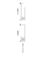
- FIG. 2A shows a load factor (CPU load factor) and a usage rate (memory usage rate) of the storage unit 24 in a predetermined period (for example, a scene where the actuator is operating) of the calculation unit 23 of the control device 20 that controls the actuator 210A.
- the average value is shown.
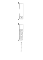
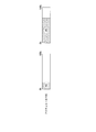
- FIG. 2B shows an average value of the CPU load rate and the memory usage rate of the actuator 210B and FIG.
- the average CPU load factor of the actuator 210A is 20%, and the average memory usage rate is 20%.
- the average CPU load factor of the actuator 210B is 70%, and the average memory usage rate is 20%.
- the average CPU load factor of the actuator 210C is 20%, and the average memory usage rate is 70%.
- the threshold for determining whether there is a margin in the memory usage rate and CPU load rate is 50%.
- the actuator 210B has a margin in the memory usage rate (20%) but does not have a margin in the CPU load rate (70%).
- the actuator 210C has a margin in the CPU load rate (20%), but has no margin in the memory usage rate (70%).
- the actuator 210A has both a CPU load factor (20%) and a memory usage rate (20%). In such a case, if the turbo ECUs 21B and 21C are mounted on the control devices 20B and 20C of the actuators 210B and 210C, resources are insufficient. Therefore, there is a possibility that a delay occurs in the processing of the turbo ECU unit 21 and the turbocharger cannot be controlled accurately.
- the turbo ECU unit 21A is mounted on the control device 20A of the actuator 210A, there is little possibility of delay in the processing of the turbo ECU unit 21A because the control device 20A has enough resources. There is also an advantage that the resources of the control device 20A can be effectively used. Therefore, in this embodiment, the availability of the resources of the control devices 20 (20A to 20C) of the actuators is grasped by preliminary verification, and the turbo ECU 21 is mounted on the control device 20A having a margin.
- the turbo ECU unit 21 when the capacity of the non-volatile memory (ROM, FLASH) is sufficient in the storage unit 24B of the control device 20B, the turbo ECU unit 21 is mounted on the storage unit 24B, and further the volatilization of the storage unit 24 of the control device 20C.
- the turbo ECU unit 21 may be executed using the calculation unit 23C and the storage unit 24C (RAM).
- the hardware of any one of the control devices 20 may be increased, and the turbo ECU 21 may be mounted on the control device 20. In general, this hardware enhancement is less costly and space-saving than the case where the hardware for the Turb ECU is provided independently.
- the supercharger is an example of an auxiliary machine that assists the output of the main machine that is a power source.
- the actuator drive unit 22 is an example of a drive control unit.
- the turbo ECU unit 21 is an example of an auxiliary machine control unit.
- the resources of the control device mounted on the actuator provided in the turbocharger can be effectively utilized, and space saving and cost reduction of the turbo ECU can be realized. Can do.
- Control system 10 Engine ECU DESCRIPTION OF SYMBOLS 20
- Control apparatus 21 Turbo ECU part 22
- Actuator drive part 23 Calculation part 24 Memory
- storage part Input / output part 26
- Communication part 100
- Engine 200 Turbocharger 210 Actuator
Landscapes
- Engineering & Computer Science (AREA)
- General Engineering & Computer Science (AREA)
- Computer Hardware Design (AREA)
- Chemical & Material Sciences (AREA)
- Combustion & Propulsion (AREA)
- Mechanical Engineering (AREA)
- Microelectronics & Electronic Packaging (AREA)
- Supercharger (AREA)
Abstract
制御装置は、動力源である主機の出力を補助する補機を駆動する駆動装置を制御する制御装置であって、前記駆動装置の制御を行うための駆動制御部と、前記駆動装置を含む前記補機が備える全ての駆動装置の制御を行い、前記補機の制御を行う補機制御部と、を備える。
Description
本発明は、制御装置、アクチュエータ、モータ装置及び過給機に関する。
本願は、2014年10月29日に、日本に出願された特願2014-219909号に基づき優先権を主張し、その内容をここに援用する。
本願は、2014年10月29日に、日本に出願された特願2014-219909号に基づき優先権を主張し、その内容をここに援用する。
ターボチャージャなどの過給機を備えたエンジンを搭載した車両が存在する。ターボチャージャは、エンジンが排出した排気ガスを利用してタービンを回転させ、そのタービンと同軸上に接続された圧縮機を回転させることで圧縮空気を生成する。ターボチャージャは、その圧縮空気をエンジンに供給することで、エンジンの出力効率を高める。
ターボチャージャを備えたエンジンの場合、制御システムには、主にエンジンを制御するためのエンジンECU(Electronic Control Unit)と、ターボチャージャを制御するためのターボECUが備えられている場合がある。その場合、エンジンECUとターボECUは、別々のハードウェアに搭載することが一般的である。
関連した技術として、特許文献1には、互いに独立したコンピュータを備えるメインECUとサブECUとからなるECUシステムが記載されている。
上述のようにターボECUを独立したハードウェアに配置することはスペースの占有、コストの増加につながる。
本発明は、上述の課題を解決することのできる制御装置、アクチュエータ、モータ装置及び過給機を提供する。
本発明の第1の態様によれば、制御装置は、動力源である主機の出力を補助する補機を駆動する駆動装置を制御する制御装置であって、前記駆動装置の制御を行うための駆動制御部と、前記駆動装置を含む前記補機が備える全ての駆動装置の制御を行い、前記補機の制御を行う補機制御部と、を備える。
本発明の第2の態様によれば、前記制御装置において、前記駆動装置は、アクチュエータである。
本発明の第3の態様によれば、前記制御装置において、前記補機は、電動式ターボチャージャであり、前記駆動装置は、モータ装置である。
本発明の第4の態様によれば、アクチュエータは、第2の態様に記載の制御装置を備える。
本発明の第5の態様によれば、モータ装置は、第3の態様に記載の制御装置を備える。
本発明の第6の態様によれば、過給機は、第4の態様に記載のアクチュエータと、第5の態様に記載のモータ装置とのうち、少なくとも一方を搭載する。
上記した制御装置、アクチュエータ、モータ装置及び過給機によれば、ターボチャージャが備えるアクチュエータ等に搭載された制御装置のリソースを有効に活用し、ターボECUの省スペース化、コストダウンを実現することができる。
以下、本発明の一実施形態によるシステムを図1、図2A、図2B、図2Cを参照して説明する。
図1は、本発明に係る一実施形態におけるターボエンジン・システムのブロック図の一例である。ターボエンジン・システムとは、ターボチャージャを搭載したエンジンとそれを制御するシステムのことをいう。本実施形態のターボエンジン・システム1は、エンジン100と、エンジンECU10と、ターボチャージャ200と、アクチュエータ210(210A、210B、210C)と、制御装置20(20A、20B、20C)とを含んで構成される。
図1は、本発明に係る一実施形態におけるターボエンジン・システムのブロック図の一例である。ターボエンジン・システムとは、ターボチャージャを搭載したエンジンとそれを制御するシステムのことをいう。本実施形態のターボエンジン・システム1は、エンジン100と、エンジンECU10と、ターボチャージャ200と、アクチュエータ210(210A、210B、210C)と、制御装置20(20A、20B、20C)とを含んで構成される。
エンジン100は、シリンダ内で燃料を燃焼させることで動力を取り出す内燃機関である。
エンジンECU10は、マイコン、メモリ、各種制御回路等から構成されている。エンジンECU11は、燃料噴射制御、点火制御などのエンジン100の動作を制御する。
ターボチャージャ200は、過給機の一種である。ターボチャージャ200は、エンジン100が排出した排気ガスを利用してタービンを回転させ、そのタービンと同軸上に接続された圧縮機を回転させて生成した圧縮空気をエンジンに供給する。
アクチュエータ210(210A、210B、210C)は、ターボチャージャ200に搭載されたターボチャージャ200を駆動する機構を備えた駆動装置である。アクチュエータ210とは、例えば、可変タービンノズルのアクチュエータや電動式ターボチャージャにおけるモータ装置である。あるいは、タービンに流入する排気ガスの流量を制御するバイパス弁の動作を制御するためのアクチュエータである。なお、電動式ターボチャージャとは、モータ装置によってタービンおよび同軸上のコンプレッサを回転させる機構を備えるターボチャージャである。電動式ターボチャージャを用いると、起動時などエンジンからの排気ガスが不足する状況でも、モータ装置によってタービンの回転を補うことができるのでターボチャージャの立ち上がり時間を短縮することができる。
制御装置20(20A、20B、20C)は、マイコン、メモリ、アクチュエータ駆動回路等から構成されるコントローラ(演算IC)である。制御装置20は、アクチュエータ210の動作を制御する。制御装置20は、アクチュエータ210と一体的に構成されていてもよい。
エンジンECU10は、マイコン、メモリ、各種制御回路等から構成されている。エンジンECU11は、燃料噴射制御、点火制御などのエンジン100の動作を制御する。
ターボチャージャ200は、過給機の一種である。ターボチャージャ200は、エンジン100が排出した排気ガスを利用してタービンを回転させ、そのタービンと同軸上に接続された圧縮機を回転させて生成した圧縮空気をエンジンに供給する。
アクチュエータ210(210A、210B、210C)は、ターボチャージャ200に搭載されたターボチャージャ200を駆動する機構を備えた駆動装置である。アクチュエータ210とは、例えば、可変タービンノズルのアクチュエータや電動式ターボチャージャにおけるモータ装置である。あるいは、タービンに流入する排気ガスの流量を制御するバイパス弁の動作を制御するためのアクチュエータである。なお、電動式ターボチャージャとは、モータ装置によってタービンおよび同軸上のコンプレッサを回転させる機構を備えるターボチャージャである。電動式ターボチャージャを用いると、起動時などエンジンからの排気ガスが不足する状況でも、モータ装置によってタービンの回転を補うことができるのでターボチャージャの立ち上がり時間を短縮することができる。
制御装置20(20A、20B、20C)は、マイコン、メモリ、アクチュエータ駆動回路等から構成されるコントローラ(演算IC)である。制御装置20は、アクチュエータ210の動作を制御する。制御装置20は、アクチュエータ210と一体的に構成されていてもよい。
エンジンECU10は、ターボエンジン・システム1を主導して制御する。しかし、ターボチャージャ200の動作については、ターボチャージャ用のECUであるターボECUに制御を任せる。例えば、エンジンECU10は、ターボECUに過給圧指令値を送信し、ターボECUは、その指令値に基づいて、ターボチャージャ200の過給圧を制御する。エンジンECU10は、ターボECUを介して、過給圧を調整することにより、エンジンの出力を制御する。
ここで、ターボECUの機能を搭載する装置について考えると、ターボECU専用にマイコン等を搭載した装置を設けるとコストの増大、スペースの占有を招くことになる。また、エンジン100とターボチャージャ200は、異なるメーカが製造することも多い。エンジンECUは、エンジンのメーカが作成し、ターボECUをターボチャージャ200のメーカが作成することが一般的である。従って、ターボECUの機能をエンジンECU10と同じハードウェア上に搭載することには様々な制約が加わり困難が伴うことが予想される。本実施形態では、ターボECUを、ターボチャージャ200に設けられたアクチュエータ210の制御装置20に実装する。このようにすると、ターボECU専用のハードウェアを導入する場合に比べ、コストダウンと省スペース化を達成することができ、ターボチャージャのメーカも、比較的自由にターボECU機能の搭載作業を行うことができる。
また、ターボECUの制御プログラムは、AUTOSAR(Automotive Open System Architecture)等の自動車ソフトウェアの標準仕様に沿って作成されており、ターボチャージャに設けられたアクチュエータやモータ装置の制御プログラムも同様の自動車ソフトウェアの標準仕様に沿って作成されている。従って、ターボチャージャメーカとアクチュエータのメーカが異なる場合でも、ターボECUの制御プログラムを、アクチュエータやモータ装置の制御装置20上に搭載することは、プログラムを他のプラットフォームに移植する場合に比べ容易である。
また、制御プログラム作成段階での同一制御装置20上のプログラムモジュール間(例えば、モータ装置におけるモータドライバのプログラムと新規に追加するターボECUの制御プログラム)の整合性確認は、自動車産業など製造業で多く導入されているモデルベース開発に則った検証により十分可能である。
また、制御プログラム作成段階での同一制御装置20上のプログラムモジュール間(例えば、モータ装置におけるモータドライバのプログラムと新規に追加するターボECUの制御プログラム)の整合性確認は、自動車産業など製造業で多く導入されているモデルベース開発に則った検証により十分可能である。
次にターボECUの機能を搭載した制御装置20について説明する。図1に示すように制御装置20は、ターボECU部21と、アクチュエータ駆動部22と、演算部23と、記憶部24と、入出力部25と、通信部26と、を備えている。
図1において、ターボECUの機能を搭載した制御装置20は、制御装置20Aであり、その他の制御装置20B、20CにはターボECUの機能が搭載されていないものとする。以下、制御装置20Aを例に、制御装置20の構成の説明を行う。
ターボECU部21Aは、ターボECUの機能を備えている。例えば、ターボECU部21Aは、エンジンECU10が指示する過給圧となるように、タービンに流入する排気ガスの流量を制御するバルブ(以下、タービン弁という)の弁開度を制御する弁開度指令信号を生成する。ターボECU部21Aは、この他にもターボチャージャの様々な機構を制御する機能を有しているが、本明細書では記載を省略する。
図1において、ターボECUの機能を搭載した制御装置20は、制御装置20Aであり、その他の制御装置20B、20CにはターボECUの機能が搭載されていないものとする。以下、制御装置20Aを例に、制御装置20の構成の説明を行う。
ターボECU部21Aは、ターボECUの機能を備えている。例えば、ターボECU部21Aは、エンジンECU10が指示する過給圧となるように、タービンに流入する排気ガスの流量を制御するバルブ(以下、タービン弁という)の弁開度を制御する弁開度指令信号を生成する。ターボECU部21Aは、この他にもターボチャージャの様々な機構を制御する機能を有しているが、本明細書では記載を省略する。
アクチュエータ駆動部22Aは、制御装置20Aが設けられたアクチュエータ210Aの動作を制御する制御信号を生成する。例えば、アクチュエータ210Aが上述のタービン弁を駆動するアクチュエータである場合、アクチュエータ駆動部22Aは、ターボECU部21が生成する弁開度指令に基づいて、タービン弁の弁開度を調節する制御信号を生成する。
演算部23Aは、DSP、マイコン、CPUなどの演算装置である。
記憶部24Aは、ROM,RAMなどのメモリである。
入出力部25Aは、自装置(制御装置20)が設けられたアクチュエータ210Aの他の装置とデータの入出力を行う。例えば、入出力部25Aは、アクチュエータ駆動部22Aが生成した制御信号をアクチュエータ210Aに出力する。
通信部26Aは、他の装置と通信を行う。例えば、通信部26は、エンジンECU10から、ターボECU部21Aへの制御信号を受信する。また、通信部26は、ターボECU部21Aが生成したアクチュエータの制御信号を、他のアクチュエータ(例えばアクチュエータ210B)へ送信する。
ターボECU部21、アクチュエータ駆動部22は、演算部23が記憶部24の記憶するプログラムを読み込んで実行することにより、制御装置20に備わる機能である。
なお、制御装置20B、制御装置20Cの構成は、制御装置20AからサブECU部21を除いた構成となる。
演算部23Aは、DSP、マイコン、CPUなどの演算装置である。
記憶部24Aは、ROM,RAMなどのメモリである。
入出力部25Aは、自装置(制御装置20)が設けられたアクチュエータ210Aの他の装置とデータの入出力を行う。例えば、入出力部25Aは、アクチュエータ駆動部22Aが生成した制御信号をアクチュエータ210Aに出力する。
通信部26Aは、他の装置と通信を行う。例えば、通信部26は、エンジンECU10から、ターボECU部21Aへの制御信号を受信する。また、通信部26は、ターボECU部21Aが生成したアクチュエータの制御信号を、他のアクチュエータ(例えばアクチュエータ210B)へ送信する。
ターボECU部21、アクチュエータ駆動部22は、演算部23が記憶部24の記憶するプログラムを読み込んで実行することにより、制御装置20に備わる機能である。
なお、制御装置20B、制御装置20Cの構成は、制御装置20AからサブECU部21を除いた構成となる。
また、ターボECU部21が搭載される制御装置20は、好ましくは、センサが一体的に組み込まれた、いわゆるスマートアクチュエータを制御する制御装置、又は、電動式ターボチャージャにおけるモータ装置に搭載された制御装置である。これら、スマートアクチュエータやモータ装置は、一般的なアクチュエータよりも複雑な制御が必要であるため、一般的なアクチュエータに組み込まれた制御装置よりも処理能力の高い制御装置が搭載される。制御装置の処理能力に余裕があればターボECU部21を搭載することが可能になる。
ターボECU部21Aは、ターボチャージャ200全体の動作を制御する。つまり、ターボECU部21Aは、アクチュエータ210A~210Cの制御信号を生成し、その制御信号を各アクチュエータ210A~210Cに出力する。アクチュエータ210Aについては、ターボECU部21Aは、アクチュエータ駆動部22Aへ制御信号を出力する。アクチュエータ210Bについては、ターボECU部21Aは、通信部26Aを介して制御装置20Bへ制御信号を出力する。制御装置20Bでは、通信部26Bを介してアクチュエータ駆動部22Bが制御信号を取得する。アクチュエータ210Cについてもアクチュエータ210Bと同様である。
ターボECUの機能が独立したハードウェアに搭載されていても、本実施形態のようにアクチュエータの制御装置20Aに搭載されていても、エンジンECU10の機能・構成に大きな影響はない。また、他のアクチュエータ210B、210Cについても同様に、ターボECUの機能がどこに搭載されても、アクチュエータ210B、210Cの機能・構成には大きな影響はない。アクチュエータ210Aについては、ターボECUからの制御信号を、通信部26Aを介して取得するか、ターボECU部21からメモリ(記憶部24A)を介して取得するかの違いだけで、ターボECUの機能をどの装置に搭載したとしても、アクチュエータ210Aの処理を行う上で大きな影響はない。また、制御装置20AにターボECU部21を搭載するのに必要なコストは、ターボECUの機能を独立したハードウェアに搭載するのに比べれば少なくて済む。本実施形態によれば、ターボECUの省スペース化、コストダウンを実現することができる。
図2Aは、本発明に係る一実施形態におけるターボECUを搭載する制御装置の選択方法を説明する第一の図である。図2Bは、本発明に係る一実施形態におけるターボECUを搭載する制御装置の選択方法を説明する第二の図である。図2Cは、本発明に係る一実施形態におけるターボECUを搭載する制御装置の選択方法を説明する第三の図である。
本実施形態では、制御装置を持つアクチュエータが複数ある場合には、演算部23の負荷率や記憶部24の使用量を比較して、最も余裕があると判断されたアクチュエータにサブECU部21を搭載する。
図2Aは、アクチュエータ210Aを制御する制御装置20の演算部23の所定の期間(例えばアクチュエータが動作している場面)における負荷率(CPU負荷率)及び記憶部24の使用率(メモリ使用率)の平均値を示している。同様に図2Bは、アクチュエータ210Bの、図2Cはアクチュエータ210Cの所定の期間におけるCPU負荷率及びメモリ使用率の平均値を示している。
アクチュエータ210Aの平均CPU負荷率は20%で、平均メモリ使用率は20%である。アクチュエータ210Bの平均CPU負荷率は70%で、平均メモリ使用率は20%である。アクチュエータ210Cの平均CPU負荷率は20%で、平均メモリ使用率は70%である。
本実施形態では、制御装置を持つアクチュエータが複数ある場合には、演算部23の負荷率や記憶部24の使用量を比較して、最も余裕があると判断されたアクチュエータにサブECU部21を搭載する。
図2Aは、アクチュエータ210Aを制御する制御装置20の演算部23の所定の期間(例えばアクチュエータが動作している場面)における負荷率(CPU負荷率)及び記憶部24の使用率(メモリ使用率)の平均値を示している。同様に図2Bは、アクチュエータ210Bの、図2Cはアクチュエータ210Cの所定の期間におけるCPU負荷率及びメモリ使用率の平均値を示している。
アクチュエータ210Aの平均CPU負荷率は20%で、平均メモリ使用率は20%である。アクチュエータ210Bの平均CPU負荷率は70%で、平均メモリ使用率は20%である。アクチュエータ210Cの平均CPU負荷率は20%で、平均メモリ使用率は70%である。
ここで、メモリ使用率及びCPU負荷率に余裕があるかどうかを判定する閾値を50%とする。アクチュエータ210Bは、メモリ使用率(20%)には余裕があるが、CPU負荷率(70%)には余裕がない。アクチュエータ210Cは、CPU負荷率(20%)には余裕があるが、メモリ使用率(70%)には余裕がない。アクチュエータ210Aは、CPU負荷率(20%)、メモリ使用率(20%)共に余裕がある。このような場合、アクチュエータ210B、210Cの制御装置20B、20CにターボECU部21B、21Cを搭載すると、リソースが不足する。そのため、ターボECU部21の処理に遅延が生じ、ターボチャージャの制御が正確にできない可能性がある。一方、アクチュエータ210Aの制御装置20Aに、ターボECU部21Aを搭載すれば、制御装置20Aのリソースには余裕があるため、ターボECU部21Aの処理に遅延が生じる可能性が少ない。また、制御装置20Aのリソースを有効に活用できるという利点も存在する。従って、本実施形態では、事前検証により各アクチュエータの制御装置20(20A~20C)のリソースの空き具合を把握し、余裕のある制御装置20AにターボECU21を搭載する。
なお、制御装置20Bの記憶部24Bのうち不揮発性メモリ(ROM、FLASH)の容量に余裕がある場合は、ターボECU部21を記憶部24Bに搭載し、さらに制御装置20Cの記憶部24の揮発性メモリ(RAM)には余裕がある場合、演算部23Cと記憶部24C(RAM)を用いてターボECU部21を実行するようにしてもよい。
また、どのアクチュエータにも十分な余裕がない場合は、どれか1つの制御装置20のハードウェアを増強し、その制御装置20にターボECU21を搭載するようにしてもよい。このハードウェア増強は、一般的には、タービECU用のハードウェアを独立して設ける場合に比べれば、コストが安く済み、省スペース化も実現できる。
また、どのアクチュエータにも十分な余裕がない場合は、どれか1つの制御装置20のハードウェアを増強し、その制御装置20にターボECU21を搭載するようにしてもよい。このハードウェア増強は、一般的には、タービECU用のハードウェアを独立して設ける場合に比べれば、コストが安く済み、省スペース化も実現できる。
本実施形態によれば、ターボECU21用の新たなハードウェアを設ける必要がないため、ターボECU21の省スペース化、コストダウンを実現することができる。
その他、本発明の趣旨を逸脱しない範囲で、上記した実施の形態における構成要素を周知の構成要素に置き換えることは適宜可能である。また、この発明の技術範囲は上記の実施形態に限られるものではなく、本発明の趣旨を逸脱しない範囲において種々の変更を加えることが可能である。なお、過給機は、動力源である主機の出力を補助する補機の一例である。アクチュエータ駆動部22は、駆動制御部の一例である。ターボECU部21は、補機制御部の一例である。
上述した制御装置、アクチュエータ、モータ装置及び過給機によれば、ターボチャージャが備えるアクチュエータ等に搭載された制御装置のリソースを有効に活用し、ターボECUの省スペース化、コストダウンを実現することができる。
1 制御システム
10 エンジンECU
20 制御装置
21 ターボECU部
22 アクチュエータ駆動部
23 演算部
24 記憶部
25 入出力部
26 通信部
100 エンジン
200 ターボチャージャ
210 アクチュエータ
10 エンジンECU
20 制御装置
21 ターボECU部
22 アクチュエータ駆動部
23 演算部
24 記憶部
25 入出力部
26 通信部
100 エンジン
200 ターボチャージャ
210 アクチュエータ
Claims (6)
- 動力源である主機の出力を補助する補機を駆動する駆動装置を制御する制御装置であって、
前記駆動装置の制御を行うための駆動制御部と、
前記駆動装置を含む前記補機が備える全ての駆動装置の制御を行い、前記補機の制御を行う補機制御部と、
を備える制御装置。 - 前記駆動装置は、アクチュエータである
請求項1に記載の制御装置。 - 前記補機は、電動式ターボチャージャであり、
前記駆動装置は、モータ装置である
請求項1に記載の制御装置。 - 請求項2に記載の制御装置を備えたアクチュエータ。
- 請求項3に記載の制御装置を備えたモータ装置。
- 請求項4に記載のアクチュエータと、請求項5に記載のモータ装置とのうち、
少なくとも一方を搭載した過給機。
Priority Applications (3)
| Application Number | Priority Date | Filing Date | Title |
|---|---|---|---|
| US15/504,682 US20170276073A1 (en) | 2014-10-29 | 2015-02-06 | Control device, actuator, motor device, and turbocharger |
| CN201580042824.8A CN106574570A (zh) | 2014-10-29 | 2015-02-06 | 控制装置、执行机构、马达装置及增压器 |
| EP15856021.9A EP3171007A4 (en) | 2014-10-29 | 2015-02-06 | Control device, actuator, motor device, and turbocharger |
Applications Claiming Priority (2)
| Application Number | Priority Date | Filing Date | Title |
|---|---|---|---|
| JP2014-219909 | 2014-10-29 | ||
| JP2014219909A JP6134306B2 (ja) | 2014-10-29 | 2014-10-29 | 制御装置、アクチュエータ、モータ装置及び過給機 |
Publications (1)
| Publication Number | Publication Date |
|---|---|
| WO2016067643A1 true WO2016067643A1 (ja) | 2016-05-06 |
Family
ID=55857004
Family Applications (1)
| Application Number | Title | Priority Date | Filing Date |
|---|---|---|---|
| PCT/JP2015/053406 Ceased WO2016067643A1 (ja) | 2014-10-29 | 2015-02-06 | 制御装置、アクチュエータ、モータ装置及び過給機 |
Country Status (5)
| Country | Link |
|---|---|
| US (1) | US20170276073A1 (ja) |
| EP (1) | EP3171007A4 (ja) |
| JP (1) | JP6134306B2 (ja) |
| CN (1) | CN106574570A (ja) |
| WO (1) | WO2016067643A1 (ja) |
Citations (6)
| Publication number | Priority date | Publication date | Assignee | Title |
|---|---|---|---|---|
| JP2003148237A (ja) * | 2001-11-08 | 2003-05-21 | Toyota Motor Corp | 内燃機関の制御装置 |
| JP2006177171A (ja) * | 2004-12-20 | 2006-07-06 | Toyota Motor Corp | 電動機付き過給機の制御装置及びその制御装置を備えた自動車 |
| JP2007127099A (ja) * | 2005-11-07 | 2007-05-24 | Toyota Motor Corp | 電動過給機 |
| JP2007187080A (ja) * | 2006-01-13 | 2007-07-26 | Mazda Motor Corp | エンジンの過給装置 |
| JP2008115751A (ja) * | 2006-11-02 | 2008-05-22 | Toyota Motor Corp | 電動過給機 |
| JP2008121477A (ja) * | 2006-11-10 | 2008-05-29 | Toyota Motor Corp | 電動過給機 |
Family Cites Families (9)
| Publication number | Priority date | Publication date | Assignee | Title |
|---|---|---|---|---|
| JPH10159576A (ja) * | 1996-11-29 | 1998-06-16 | Aisin Seiki Co Ltd | 回転電機付ターボチャージャの制御装置 |
| ATE314565T1 (de) * | 2000-03-03 | 2006-01-15 | Honeywell Int Inc | Intelligenter elektrischer stellantrieb zur steuerung eines turboladers mit integriertem abgasrückführungsventil |
| US6360541B2 (en) * | 2000-03-03 | 2002-03-26 | Honeywell International, Inc. | Intelligent electric actuator for control of a turbocharger with an integrated exhaust gas recirculation valve |
| US6705084B2 (en) * | 2001-07-03 | 2004-03-16 | Honeywell International Inc. | Control system for electric assisted turbocharger |
| JP2004106663A (ja) * | 2002-09-17 | 2004-04-08 | Toyota Motor Corp | 総合駆動制御システムおよび総合駆動制御方法 |
| JP4415912B2 (ja) * | 2004-10-06 | 2010-02-17 | 株式会社デンソー | エンジン制御システム |
| CN100404834C (zh) * | 2004-10-06 | 2008-07-23 | 株式会社电装 | 发动机控制系统 |
| EP1848882A1 (en) * | 2005-02-16 | 2007-10-31 | Honeywell International, Inc. | Turbocharging device and control method for controlling the turbocharging device |
| EP1749990B1 (en) * | 2005-08-03 | 2013-07-03 | Honda Motor Co., Ltd. | An engine system with a supercharger |
-
2014
- 2014-10-29 JP JP2014219909A patent/JP6134306B2/ja not_active Expired - Fee Related
-
2015
- 2015-02-06 EP EP15856021.9A patent/EP3171007A4/en not_active Withdrawn
- 2015-02-06 WO PCT/JP2015/053406 patent/WO2016067643A1/ja not_active Ceased
- 2015-02-06 CN CN201580042824.8A patent/CN106574570A/zh active Pending
- 2015-02-06 US US15/504,682 patent/US20170276073A1/en not_active Abandoned
Patent Citations (6)
| Publication number | Priority date | Publication date | Assignee | Title |
|---|---|---|---|---|
| JP2003148237A (ja) * | 2001-11-08 | 2003-05-21 | Toyota Motor Corp | 内燃機関の制御装置 |
| JP2006177171A (ja) * | 2004-12-20 | 2006-07-06 | Toyota Motor Corp | 電動機付き過給機の制御装置及びその制御装置を備えた自動車 |
| JP2007127099A (ja) * | 2005-11-07 | 2007-05-24 | Toyota Motor Corp | 電動過給機 |
| JP2007187080A (ja) * | 2006-01-13 | 2007-07-26 | Mazda Motor Corp | エンジンの過給装置 |
| JP2008115751A (ja) * | 2006-11-02 | 2008-05-22 | Toyota Motor Corp | 電動過給機 |
| JP2008121477A (ja) * | 2006-11-10 | 2008-05-29 | Toyota Motor Corp | 電動過給機 |
Non-Patent Citations (1)
| Title |
|---|
| See also references of EP3171007A4 * |
Also Published As
| Publication number | Publication date |
|---|---|
| JP6134306B2 (ja) | 2017-05-24 |
| JP2016084792A (ja) | 2016-05-19 |
| EP3171007A1 (en) | 2017-05-24 |
| US20170276073A1 (en) | 2017-09-28 |
| CN106574570A (zh) | 2017-04-19 |
| EP3171007A4 (en) | 2017-11-08 |
Similar Documents
| Publication | Publication Date | Title |
|---|---|---|
| US6418719B2 (en) | Control of a variable geometry turbocharger by sensing exhaust pressure | |
| JP2008157236A (ja) | モデルに基づくターボチャージャ制御 | |
| US20130008161A1 (en) | Charged internal combustion engine | |
| CN112377296B (zh) | 增压器控制方法、装置、车辆及存储介质 | |
| CN105545451A (zh) | 用于汽车内燃机的冷却系统的冷却剂泵和/或控制阀的控制 | |
| CN104373231A (zh) | 发动机控制方法和系统 | |
| CN104373230A (zh) | 发动机控制方法和系统 | |
| JP2014163320A (ja) | 制御装置 | |
| JP6824421B2 (ja) | 圧縮空気タービン直流発電機システム | |
| CN101457689A (zh) | 用于运行压缩机的方法 | |
| WO2016067643A1 (ja) | 制御装置、アクチュエータ、モータ装置及び過給機 | |
| CN110914530B (zh) | 用于致动燃料泵的紧急操作方法 | |
| US20130060450A1 (en) | Method and device for performing a control, in particular for use in a motor vehicle | |
| JP5080643B2 (ja) | 内燃機械用のスーパーチャージャ・システムの制御装置 | |
| CN107228020B (zh) | 运行机动车驱动装置的方法以及相应的驱动装置 | |
| US8823312B2 (en) | Electric motor assembly, method for operating an electric motor, and motor control device | |
| JP5306162B2 (ja) | 燃料ポンプ制御装置 | |
| KR20160077560A (ko) | 전자식 웨이스트 게이트를 통한 림프홈 모드 제어 방법 및 시스템 | |
| JP5005249B2 (ja) | 車両搭載用クレーンの圧油供給量制御装置 | |
| JP2014215871A (ja) | 電子制御装置 | |
| KR20170067523A (ko) | 하이브리드 차량의 제어 장치 및 방법 | |
| CN114198494B (zh) | 驱动装置 | |
| US9043084B2 (en) | Method for configuring a control apparatus for a motor vehicle, computer program and control apparatus | |
| JP4591290B2 (ja) | エンジンの過給装置 | |
| CN109983644A (zh) | 用于调节耗电器的功率的方法和设备 |
Legal Events
| Date | Code | Title | Description |
|---|---|---|---|
| 121 | Ep: the epo has been informed by wipo that ep was designated in this application |
Ref document number: 15856021 Country of ref document: EP Kind code of ref document: A1 |
|
| REEP | Request for entry into the european phase |
Ref document number: 2015856021 Country of ref document: EP |
|
| WWE | Wipo information: entry into national phase |
Ref document number: 2015856021 Country of ref document: EP |
|
| WWE | Wipo information: entry into national phase |
Ref document number: 15504682 Country of ref document: US |
|
| NENP | Non-entry into the national phase |
Ref country code: DE |