WO2016067645A1 - 車両用ドアラッチ装置 - Google Patents
車両用ドアラッチ装置 Download PDFInfo
- Publication number
- WO2016067645A1 WO2016067645A1 PCT/JP2015/055301 JP2015055301W WO2016067645A1 WO 2016067645 A1 WO2016067645 A1 WO 2016067645A1 JP 2015055301 W JP2015055301 W JP 2015055301W WO 2016067645 A1 WO2016067645 A1 WO 2016067645A1
- Authority
- WO
- WIPO (PCT)
- Prior art keywords
- auxiliary cover
- cover
- hinge shaft
- casing
- open position
- Prior art date
- Legal status (The legal status is an assumption and is not a legal conclusion. Google has not performed a legal analysis and makes no representation as to the accuracy of the status listed.)
- Ceased
Links
Images


Classifications
-
- E—FIXED CONSTRUCTIONS
- E05—LOCKS; KEYS; WINDOW OR DOOR FITTINGS; SAFES
- E05B—LOCKS; ACCESSORIES THEREFOR; HANDCUFFS
- E05B85/00—Details of vehicle locks not provided for in groups E05B77/00 - E05B83/00
- E05B85/02—Lock casings
-
- B—PERFORMING OPERATIONS; TRANSPORTING
- B60—VEHICLES IN GENERAL
- B60J—WINDOWS, WINDSCREENS, NON-FIXED ROOFS, DOORS, OR SIMILAR DEVICES FOR VEHICLES; REMOVABLE EXTERNAL PROTECTIVE COVERINGS SPECIALLY ADAPTED FOR VEHICLES
- B60J5/00—Doors
-
- E—FIXED CONSTRUCTIONS
- E05—LOCKS; KEYS; WINDOW OR DOOR FITTINGS; SAFES
- E05B—LOCKS; ACCESSORIES THEREFOR; HANDCUFFS
- E05B79/00—Mounting or connecting vehicle locks or parts thereof
- E05B79/10—Connections between movable lock parts
- E05B79/20—Connections between movable lock parts using flexible connections, e.g. Bowden cables
Definitions
- the present invention relates to a vehicle door latch device.
- an end of an operation lever that is rotatably accommodated in a casing (housing) is exposed from an opening provided in the casing, and an operation force transmitting member is provided at the end of the operation lever.
- an auxiliary cover (cover) see, for example, Patent Document 1.
- the auxiliary cover described in Patent Document 1 can be turned to a closed position for closing the connection portion of the operation lever and the operation cable and an end portion of the operation cable, and an open position for opening those portions.
- the casing is pivotally supported so as to be rotatable and detachable.
- the auxiliary cover in the open position rotates freely, so that the auxiliary cover is in the open position so that it does not interfere with the assembly work of the door latch device to the door or the operation of connecting the operation lever and the operation cable.
- Temporary fixing means for temporary holding is provided.
- the structure of the hinge portion that pivotally supports the auxiliary cover on the casing is complex, and the temporary fixing means for temporarily holding the auxiliary cover in the open position includes the casing. Since it is provided on both the cover side and the cover side and the structure thereof is complicated, there is a problem that the cost for molding the casing and the auxiliary cover increases.
- an object of the present invention is to provide a vehicle door latch device in which an auxiliary cover can be temporarily held by being stopped at an open position by simple means.
- 1st invention can connect the connection part which is a terminal and the terminal of the operation force transmission member which is provided in the said casing and can transmit the operation force of an operating device through the opening part provided in the said casing.
- An operation lever having a connected portion and the casing are formed separately from each other, and a connecting region portion including a portion in which the connecting portion of the operating force transmission member is connected to the connected portion of the operating lever can be closed.
- a vehicle door latch device comprising an auxiliary cover
- One of the casing and the auxiliary cover is provided with a hinge shaft, and the other is provided with a pair of elastic holding pieces facing each other, and the hinge shaft is provided between the elastic holding pieces.
- the auxiliary cover is provided with a stoppered portion, and is fitted to the closed position for closing the connecting region portion and the open position for opening the connecting region portion.
- a contactable stopper portion is provided and the auxiliary cover is rotated in the opening direction, the stopper portion moves over the tip of the stopper portion and moves to the opposite side, and the auxiliary cover rotates in the closing direction. In this case, the auxiliary cover can be temporarily held in the open position.
- a rotation restricting portion capable of temporarily holding the auxiliary cover in the second open position by restricting relative rotation between the hinge shaft and the elastic holding piece is provided.
- the hinge shaft has a substantially elliptical cross-sectional shape, and the rotation restricting portion is provided on the outer circumferential surface in the major axis direction.
- the rotation restricting portions are provided on both outer circumferential surfaces of the hinge shaft in the major axis direction so as to be parallel to each other, and the both rotation restricting portions are both elastically held.
- the auxiliary cover is temporarily held at the second open position opened approximately 180 degrees by elastically contacting the opposing surface of the piece.
- the hinge shaft provided on one of the casing and the auxiliary cover is rotatably fitted between a pair of elastic holding pieces provided on the other, and the auxiliary cover is rotated in the open position direction.
- the stopper part moves over the tip of the stopper part and moves to the opposite side to prevent the auxiliary cover from rotating in the closing direction, so that the auxiliary cover can be temporarily held in the open position.
- the structure of the means for temporarily holding the cover in the open position is simpler than the temporary fixing means of the conventional door latch device, and the cost for molding the casing and the auxiliary cover is reduced.
- FIG. 6 is an enlarged sectional view taken along line VIII-VIII in FIG. 5.
- FIG. 6 is an enlarged cross-sectional view taken along the line IX-IX in FIG. 5.
- It is an expanded sectional view of the same site
- it is an expanded sectional view of the state where the auxiliary cover was temporarily held in the second open position.
- FIG. 6 It is an expanded sectional view of the same site
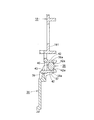
- FIGS. 1 to 9 show a door latch device according to a first embodiment of the present invention.
- the door latch device 1 is, for example, a door in a right front door (hereinafter referred to as a door) D of a vehicle.
- D is fixed to the rear end portion of the inner panel D1, and includes a meshing unit 2 for holding the door D in a closed state and an operation unit 3 for operating the meshing unit 2. 2 and the operation unit 3 are integrated.
- the meshing unit 2 is made of a synthetic resin box-like body 4 and fixed to the rear surface of the body 4 and is fixed to the rear part of the inner panel D1 in the door D together with the body 4 by three bolts 5.
- a meshing mechanism 7 that restrains the door in a closed state is accommodated.
- the body 4 and the cover plate 6 are formed with substantially the same shape of the striker entry groove 9 into which the striker 8 on the vehicle body side enters as the door D is closed.
- One female screw hole 10a is formed above the striker entry groove 9 in the cover plate 6, and two front and rear female screw holes 10b and 10c are formed downward by burring.
- the meshing unit 2 is fixed to the inner panel D1 by screwing the bolts 5 into the female screw holes 10a, 10b, and 10c (see FIG. 1).
- the meshing mechanism 7 is pivotally supported in the body 4 by a pivot 11 and is urged in an open direction (clockwise in FIG. 2) by a spring (not shown) to engage with the striker 8. And a ratchet 14 which is pivotally supported by a pivot 13 and engageable with the outer peripheral edge of the latch 12.
- a locking lever 20 (to be described later) of the operation unit 3 is in the unlock position, an outside handle provided on the outside of the door D or an inside handle provided on the inside of the vehicle (both not shown) is opened.
- an outside lever 24 or an inside lever 22 described later is rotated based on the operation, a ratchet engaged with the outer peripheral edge of the latch 12 by an open lever (not shown) linked to the outside lever 24.
- the door D can be opened by being operated to release and rotating in the release direction (clockwise in FIG. 2).
- the operation unit 3 includes a synthetic resin casing 15 having a substantially L shape in plan view.
- the casing 15 is disposed in the door D in the vicinity of the side surface on the inner side of the inner panel D1, and has a first casing 151 made of synthetic resin having an operation mechanism accommodating portion 16 that opens on the inner side of the inner panel D1.
- a second casing 152 made of synthetic resin having a body housing portion 17 that extends from the rear end portion of the middle portion in the vertical direction toward the outside of the vehicle at a substantially right angle and opens on the rear surface side, and housing the operating mechanism of the first casing 151.
- a synthetic resin cover 18 that closes the opening of the portion 16 by exposing the vicinity of the striker entry groove 9 of the body 4 in the meshing unit 2 is provided.
- the operation mechanism includes an actuator (not shown) including a motor that automatically performs a lock / unlock operation, a key lever (not shown) that interlocks with the operation of the key cylinder, and a lock knob (not shown) provided on the inner side of the door D.
- a locking lever 20 that is linked to a locking position and an unlocking position by an operation of a lock knob or an actuator, and a door D.
- the inside handle (not shown) provided inside the vehicle is linked via a second Bowden cable 21 (see FIG. 5), which is an operation force transmission member, and is rotated in conjunction with the opening operation of the inside handle.
- the components of the operation mechanism are not directly related to the present invention, and are well-known components incorporated in a normal door latch device, and thus detailed description thereof is omitted.
- a support shaft 23 in the front-rear direction is integrally provided rearwardly on the lower portion of the rear surface of the second casing 152 protruding downward from the meshing unit 2.
- An intermediate portion of the outside lever 24 facing inward and outward is pivotally supported so that an end portion on the outer side of the vehicle protrudes from the second casing 152 so as to be rotatable in the vertical direction.
- the rear surface of the support shaft 23 and the rear surface in the vicinity of the middle portion of the outside lever 24 are covered with the lower end portion of a metal back plate 25 that is fixed to the front surface (back surface) of the body 4 and faces the vertical direction. .
- a female screw hole 26 is formed in the lower end portion of the back plate 25 facing the support shaft 23, and a bolt 27 inserted from the front side of the second casing 152 is threaded into the female screw hole 26 through the support shaft 23.
- the intermediate portion of the outside lever 24 is rotatably held on the opposing surface of the second casing 152 and the back plate 25.
- the end of the outside lever 24 on the vehicle inner side is connected to an open lever (not shown) that forms part of the operation mechanism housed in the operation mechanism housing portion 16 in the first casing 151.
- a bowl-shaped upper rainwater guide protrusion 28 and a lower rainwater guide protrusion 29 that protrude in the vehicle direction and incline rearwardly downward. Is formed.
- the upper rainwater guide protrusions 28 and the lower rainwater guide protrusions 29 are for guiding rainwater that flows down the surface of the cover 18 to the rear and downward to prevent the rainwater from flowing toward the cable connection region 181 described later. It is.
- the cable connection region portion 181 is provided along the lower rainwater guide projection 29 and the front edge of the cover 18, and the front wall portion 30 in the oblique vertical direction protruding toward the vehicle interior, and the bottom inclined to the rear downward of the cover 18. It is provided along the edge and surrounded by a lower wall portion 31 in the front-rear direction that protrudes toward the inside of the vehicle.
- the cable connection region portion 181 is opposed to the front wall portion 30 and protrudes in the vertical direction in the up-down direction, and in the up-and-down direction which faces it slightly behind the intermediate wall portion 32 and protrudes in the in-vehicle direction.
- the cable holding portion 33 of the casing 15 is opened to communicate with the inside of the operation mechanism accommodating portion 16 of the casing 15, and the elongated hole 34 having a shape along the turning locus of the lower end portion of the locking lever 20 is used.
- a lower end portion of the inside lever 22 protrudes toward the cable connection region 181 side, and a notch 35 having a shape along a rotation locus of the lower end portion is formed.
- the front wall portion 30 is formed with two fitting grooves 30a and 30a into which the ends of the outer tubes 191 and 211 of the first and second Bowden cables 19 and 21 are fitted, respectively.
- both large diameter end portions are fitted into the cable holding portion 33 by fitting respective annular grooves formed at the distal end portions of the large diameter end portions 192 and 212 of the first and second Bowden cables 19 and 21.
- Holding grooves 33a and 33a for holding 192 and 212 in an axially immovable manner are formed.
- a connecting portion 193a having a spherical shape at a terminal portion of the inner cable 193 in the first Bowden cable 19 is fitted into a hemispherical concave portion 20a formed at the lower end portion of the locking lever 20 and opened through the elongated hole 34.
- a connecting portion 213 a that forms an axial shape of the end portion of the inner cable 213 in the second Bowden cable 21 is fitted in a fitting hole 22 a formed in a lower end portion protruding from the notch 35 in the inside lever 22.
- Both the connecting portions 193a and 213a are prevented from being detached from the recess 20a and the fitting hole 22a by an auxiliary cover 36 described later that closes the cable connecting region 181.
- the concave portion 20a of the locking lever 20 and the fitting hole 22a of the inside lever 22 correspond to a connected portion.
- the cable connection region 181 is closed by a synthetic resin auxiliary cover 36 which is separate from the cover 18 after the first and second Bowden cables 19 and 21 are connected to the locking lever 20 and the inside lever 22, respectively. It has become.
- the auxiliary cover 36 has substantially the same shape as the cable connection region portion 181, and the front edge contacts the front surface of the front wall portion 30 of the cover 18 in a state where the cable connection region portion 181 is closed.
- the side wall part 361 which protrudes is protruded toward the cable connection area
- the auxiliary cover 36 has an upper wall portion 362 that can come into contact with the side surface on the vehicle inner side in the lower portion close to the lower rainwater guiding projection 29 of the cover 18 in a state where the cable connection region portion 181 is closed. 361 protrudes in the direction of the cable connection region 181 so as to be continuous with 361.
- the side wall 361 is formed with presser grooves 361a and 361a that can hold and hold the outer tubes 191 and 211 of the first and second Bowden cables 19 and 21 from the vehicle inner side in a state where the cable connection region 181 is closed. ing.
- the front portion of the back surface of the auxiliary cover 36 (the surface facing it when the cable connection region portion 181 is closed) is intermediate the front wall portion 30 of the cover 18 when the cable connection region portion 181 is closed.
- the first intermediate side wall portion 363 located between the wall portions 32 and the second intermediate side wall portion 364 located between the intermediate wall portion 32 of the cover 18 and the cable holding portion 33 are each directed toward the cable connection region portion 181. It is protruding.
- the first intermediate side wall 363 and the second intermediate side wall 364 hold the large-diameter ends 192 and 212 of the first and second Bowden cables 19 and 21 from the inside of the vehicle in a state where the cable connection region 181 is closed.
- the presser grooves 363a and 364a are formed in the upper and lower two pieces that can be held in this manner.
- the upper end of the auxiliary cover 36 (the lower end in the state where the cable connection region 181 is closed) 365 is located at the center in the front-rear direction and the front is bent back and forth.
- a pair of projecting pieces 37, 37 are integrally projected upward, and a hinge shaft 38 facing in the front-rear direction is spaced apart in parallel with the upper end surface 365 between the opposing surfaces of the tip portions of both projecting pieces 37. In this manner, the protrusions 37 are integrally provided.
- the cross-sectional shape orthogonal to the longitudinal direction of the hinge shaft 38 is substantially elliptical, and flat portions 38a and 38a that are parallel to each other are formed in the longitudinal direction (front-rear direction) on the upper and lower outer peripheral surfaces that are the major axis direction. It is formed along.
- the dimension between the upper and lower flat portions 38a, 38a is slightly smaller than the dimension between the opposing surfaces of a pair of upper and lower elastic holding pieces 42, 42 described later provided on the cover 18.
- a central portion between the front and rear projecting pieces 37 on the upper end surface 365 of the auxiliary cover 36 rotates around the hinge shaft 38 together with the auxiliary cover 36, thereby overcoming a stopper portion 43, which will be described later, provided on the cover 18.
- a tapered stoppered portion 39 that can move to the opposite side is provided so as to protrude upward (downward when the cable connection region portion 181 is closed).
- the auxiliary cover has a rectangular opening 40 at the center in the front-rear direction of the lower end of the cable connection region 181 in the cover 18 that forms a part of the casing 15.
- a plate-like mounting portion 41 for mounting 36 is provided so as to protrude downward, and a pair of upper and lower elastic holding pieces for rotatably holding the hinge shaft 38 of the auxiliary cover 36 is provided on the inner surface of the mounting portion 41.
- 42 and 42 are integrally projected toward the in-vehicle direction so as to face each other with the opening 40 interposed therebetween.
- Claw portions 42a and 42a that are opposed to each other are projected inwardly at the tip portions of the upper and lower elastic holding pieces 42.
- the dimension between the opposing surfaces of the two claw portions 42a is slightly smaller than the minimum outer diameter dimension of the hinge shaft 38 in the short axis direction so that the hinge shaft 38 fitted between the two elastic holding pieces 42 is not detached. ing.
- the stopper cover 39 comes into contact with the upper end of the lower elastic holding piece 42 from above to temporarily hold the auxiliary cover 36 at the first open position.
- the stopper portion 43 is integrally connected so as to be positioned on the rotation locus of the tip portion of the stopper portion 39 (detailed description will be described later).
- the front end portion and the rear portion of the back surface adjacent to the upper end surface 365 of the auxiliary cover 36 face the vehicle outward direction in a state where the cable connection region portion 181 is closed, and the engagement claws 45 a at the front end portion. Engagement pieces 45 and 45 having a 45a are projected. Engaging claw portions 46 and 46 project from the lower surfaces of the front and rear end portions of the upper wall portion 362 of the auxiliary cover 36 (the upper surface when the cable connection region portion 181 is closed).
- the front and rear engaging pieces 45 When the cable connecting region 181 is closed by the auxiliary cover 36, the front and rear engaging pieces 45 have engaging holes 47 provided at the front end and the rear of the lower end of the cable connecting region 181 in the cover 18, 47, and the engaging claws 45a and 45a are engaged with the opening edges of their rear ends. Further, the engaging claws 46 are engaged claws provided at both front and rear ends of the lower surface of the lower rainwater guiding protrusion 29 in the cover 18 when the cable connection region 181 is closed by the auxiliary cover 36. It engages with the parts 48, 48. By means of the two engagement front and rear engagement 45 and engagement claw portions 46, the four locations of the auxiliary cover 36 are stably fixed to the cable connection region portion 181 of the cover 18 without any difficulty.
- a hinge shaft 38 provided on the auxiliary cover 36 is fitted between the upper and lower elastic holding pieces 42 while elastically deforming both elastic holding pieces 42 in the expanding direction. To do. At this time, when the hinge shaft 38 is fitted from the long axis direction, the elastic deformation amount of both elastic holding pieces 42 becomes small, so that the fitting is easy.
- the auxiliary cover 36 is temporarily held at a closed position for closing the cable connection region 181 and at a position opened, for example, approximately 210 degrees from the closed position as shown in FIGS.
- the first open position can be rotated up and down around the hinge shaft 38.
- the stopper portion 43 is elastically deformed downward by the stopper portion 39, contrary to the above, so that the auxiliary cover 36 is moved to the closing position direction. It can be rotated without hindrance. If the hinged shaft 38 can be moved greatly to the opening 40 side so that the stopper portion 39 gets over the tip of the stopper portion 43, the stopper portion 43 is not elastically deformed by the stopper portion 39. It is also possible to temporarily hold the auxiliary cover 36 in the first open position by bringing the lower surface of the stopper portion 39 into contact with the upper surface of the stopper portion 43.
- the auxiliary cover 36 when the auxiliary cover 36 can be temporarily held in the first open position, the auxiliary cover 36 is reliably prevented from rotating in the closing direction, so that the door latch device can be assembled in the door D or the cable.
- the first and second Bowden cables 19 and 21 are assembled to the connection region 181 or when the inner cables 193 and 213 are connected to the locking lever 20 and the inside lever 22, the auxiliary cover 36 rotates unnaturally. There is no risk of getting in the way, and the workability can be improved.
- the hinge shaft 38 provided on the auxiliary cover 36 can be rotated between the pair of elastic holding pieces 42 and 42 provided on the cover 18.
- the stopper 39 moves over the tip of the stopper 43 and moves to the opposite side to prevent the auxiliary cover 36 from rotating in the closing direction. Since the auxiliary cover 36 can be temporarily held in the first open position, the structure of the means for temporarily holding the auxiliary cover 36 in the first open position is simpler than the temporary fixing means of the conventional door latch device. The cost for molding the casing 15 and the auxiliary cover 36 is reduced.
- FIG.10 and FIG.11 shows sectional drawing of the auxiliary
- the upper and lower flat portions 38a, 38a formed on the hinge shaft 38 are used as rotation restricting portions so that the auxiliary cover 36 can be temporarily held at the second open position opened almost 180 degrees. It is a thing.
- the dimension between the opposing surfaces of the upper and lower elastic holding pieces 42, 42 is more required than the vertical dimension between the upper and lower flat portions (rotation restricting portions) 38a, 38a of the hinge shaft 38.
- the auxiliary cover 36 is fitted between the elastic holding pieces 42 when the auxiliary cover 36 is in the closed position for closing the cable connection area 181 and the second open position for rotating the cable 180 by 180 degrees to open the cable connection area 181.
- the opposing surfaces of the two elastic holding pieces 42 can be elastically pressed against the upper and lower flat portions 38a, 38a of the combined hinge shaft 38.
- both elastic holdings are maintained when the auxiliary cover 36 is in the closed position and the second open position.
- the amount of elastic deformation of the piece 42 in the expanding direction is maximized, and the reaction force is also maximized.
- both elastic holding pieces 42 are in strong pressure contact with the upper and lower flat portions 38a, the relative rotation between the hinge shaft 38 and both elastic holding pieces 42 is restricted, and the auxiliary cover 36 is stopped at the second open position.
- the holding force for temporary holding becomes large.
- the auxiliary cover 36 rotates from the closed position toward the second opening position or vice versa, the elastic deformation amount of both elastic holding pieces 42 gradually decreases, and the pressing force applied to the hinge shaft 38 is reduced. Therefore, the auxiliary cover 36 can be rotated without resistance.
- the auxiliary cover 36 in the closed position when the auxiliary cover 36 in the closed position is rotated 180 degrees in the opening direction, the opposing surfaces of the upper and lower elastic holding pieces 42 of the cover 18 are hinge shafts as described above.
- the upper cover 38 is elastically pressed against the upper and lower flat portions 38 a, the relative rotation between the hinge shaft 38 and both elastic holding pieces 42 is restricted, and the rotation of the auxiliary cover 36 in the opening and closing direction is also restricted.
- 36 is stopped and temporarily held at the second opening position opened 180 degrees.
- the tip (upper end) of the stopper portion 39 approaches or contacts the lower surface of the stopper portion 43. Does not rotate beyond the second open position.
- the auxiliary cover 36 if the auxiliary cover 36 is rotated beyond the second open position, the auxiliary cover 36 is temporarily held in the first open position as in the first embodiment. Is also possible.
- the auxiliary cover 36 is provided with a substantially elliptic hinge shaft 38 having flat portions (rotation restricting portions) 38a, 38a parallel to each other on the upper and lower outer peripheral surfaces.
- the auxiliary cover 36 can be temporarily held by being stopped at the second open position opened 180 degrees, so that the configuration of the means for temporarily holding the auxiliary cover 36 in the open position is compared with the temporary fixing means of the conventional door latch device.
- the cost for molding the cover 18 and the auxiliary cover 36 is reduced.
- auxiliary cover 36 can be stopped and temporarily held at the second open position opened 180 degrees, as in the first embodiment, the assembly workability when the door latch device is assembled in the door D, The workability of assembling the first and second Bowden cables 19 and 21 to the cable connection region 181 can be improved.
- the hinge shaft 38 is provided on the auxiliary cover 36 side, and this hinge shaft 38 is fitted between the pair of upper and lower elastic holding pieces 42 provided on the cover 18 side. May be reversed as shown in FIG. That is, for example, a pair of opposing mounting portions 49 for attaching the auxiliary cover 36 are provided on the lower surface of the cover 18 so as to protrude downward, and between the opposing surfaces of the both mounting portions 49, the same as in the first embodiment.
- a hinge shaft 38 is provided, and a pair of upper and lower elastic holding pieces 42, 42 protruding from the lower surface of the auxiliary cover 36 and fitted in the hinge shaft 38 are fitted in a freely rotatable manner from the inside of the vehicle.
- a stoppered portion 39 and a stopper portion 43 similar to those in the above embodiment are provided on the lower end portion (upper end portion in the closed state) of the auxiliary cover 36 and the lower surface of the cover 18, respectively, and the auxiliary cover 36 is turned 180 degrees.
- the stopper portion 39 gets over the stopper portion 43 when it is rotated in the opening direction to the position exceeding the first position, the auxiliary cover 36 is moved to the first position as in the first embodiment. It can be temporarily held by being stopped at the open position.
- the flat portions (rotation restricting portions) 38a are provided on the upper and lower surfaces of the hinge shaft 38 in the major axis direction, but the upper and lower flat portions 38a may be omitted. . Even in this case, when the auxiliary cover 36 is rotated 180 degrees, either one of the flat portions 38a is elastically pressed against either one of the upper and lower elastic holding pieces 42, so that the auxiliary cover 36 is opened to the second position. Temporarily held in position. When either one of the upper and lower flat portions 38a is omitted, in order to increase the temporary holding force of the auxiliary cover 36 by the elastic holding pieces 42, the front and rear dimensions (width dimensions) of the flat portions 38a are set as described above. It should be larger than the form.
- the hinge shaft 38 and the elastic holding piece 42 are provided at the center portions in the front-rear direction of the auxiliary cover 36 and the cover 18, respectively. You may provide in two places of a part.
- the cross-sectional shape of the hinge shaft 38 may be circular, and a flat portion 38a may be provided on both upper and lower surfaces or any one of the surfaces.
Landscapes
- Engineering & Computer Science (AREA)
- Mechanical Engineering (AREA)
- Lock And Its Accessories (AREA)
Abstract
簡単な手段で、補助カバーを開放位置に停止させて仮保持しうるようにした車両用ドアラッチ装置を提供する。 補助カバー36に設けたヒンジ軸38を、ケーシングの一部をなすカバー18に設けた1対の弾性保持片42間に回転可能に嵌合し、補助カバー36に被ストッパ部39を、カバー18に、被ストッパ部39が当接可能なストッパ部43を設け、補助カバー36を開方向へ回転させた場合に、被ストッパ部39がストッパ部43の先端部を乗り越えて反対側に移動することにより、補助カバー36を開放位置に仮保持しうるようにする。
Description
本発明は、車両用ドアラッチ装置に関する。
従来の車両用ドアラッチ装置には、ケーシング(ハウジング)内に回動可能に収容された操作レバーの端部を、ケーシングに設けた開口より露出させて、操作レバーの端部に、操作力伝達部材である操作ケーブルの端末部を連結した後、それらの連結部と操作ケーブルの端部を、補助カバー(カバー)により覆ったものがある(例えば特許文献1参照)。
この特許文献1に記載の補助カバーは、操作レバーと操作ケーブルとの連結部及び操作ケーブルの端部を閉塞する閉塞位置と、それらの部分を開放する開放位置とに回動しうるように、ケーシングに回転可能かつ着脱可能に枢支されている。
また、開放位置にある補助カバーが自由に回転して、ドアへのドアラッチ装置の組付作業や、操作レバーと操作ケーブルとの連結作業に支障を来さないように、補助カバーを開放位置に仮保持するための仮止め手段が設けられている。
また、開放位置にある補助カバーが自由に回転して、ドアへのドアラッチ装置の組付作業や、操作レバーと操作ケーブルとの連結作業に支障を来さないように、補助カバーを開放位置に仮保持するための仮止め手段が設けられている。
上記特許文献1に記載のドアラッチ装置においては、ケーシングに補助カバーを回転可能に枢支するヒンジ部の構造が複雑であるとともに、補助カバーを開放位置に仮保持するための仮止め手段が、ケーシング側とカバー側の両方に設けられ、かつその構造も複雑であるので、ケーシングや補助カバーを成形する際のコストが増大するという問題がある。
本発明は、上記問題点に鑑み、簡単な手段で、補助カバーを開放位置に停止させて仮保持しうるようにした車両用ドアラッチ装置を提供することを目的としている。
本発明によると、上記課題は、次のようにして解決される。
第1の発明は、ケーシングと、前記ケーシング内に設けられ、操作装置の操作力を伝達可能な操作力伝達部材の端末である連結部を、前記ケーシングに設けた開口部を介して連結可能な被連結部を有する操作レバーと、前記ケーシングとは別体に形成され、前記操作レバーの前記被連結部に前記操作力伝達部材の前記連結部を連結した部分を含む連結領域部を閉塞可能な補助カバーとを備える車両用ドアラッチ装置において、
前記ケーシングと前記補助カバーとのいずれか一方にヒンジ軸を、同じく他方に、互いに対向する1対の弾性保持片をそれぞれ設け、前記両弾性保持片間に、前記ヒンジ軸を、前記補助カバーが前記連結領域部を閉塞する閉塞位置及び前記連結領域部を開放する開放位置に回転しうるように嵌合し、前記補助カバーに被ストッパ部を設けるとともに、前記ケーシングに、前記被ストッパ部が当接可能なストッパ部を設け、前記補助カバーを開方向へ回転させた場合に、前記被ストッパ部が前記ストッパ部の先端部を乗り越えて反対側に移動し、前記補助カバーの閉方向への回転を阻止することにより、前記補助カバーを前記開放位置に仮保持しうるようにしたことを特徴としている。
第2の発明は、上記第1の発明において、前記ヒンジ軸の外周面に、前記補助カバーを開方向へ回転させた場合に、前記両弾性保持片の対向面の少なくともいずれか一方に弾性的に面接触し、前記ヒンジ軸と前記弾性保持片との相対回転を規制することにより、前記補助カバーを第2開放位置に仮保持可能な回転規制部を設けたことを特徴としている。
第3の発明は、上記第2の発明において、前記ヒンジ軸の横断面形状をほぼ楕円形とし、その長軸方向の外周面に前記回転規制部を設けたことを特徴とする請求項2に記載の車両用ドアラッチ装置。
第4の発明は、上記第3の発明において、前記ヒンジ軸における長軸方向の両外周面に、前記回転規制部を、互いに平行をなすように設け、前記両回転規制部が前記両弾性保持片の対向面に弾性的に面接触することにより、前記補助カバーがほぼ180度開いた第2開放位置に仮保持されるようにしたことを特徴としている。
本発明によると、ケーシングと補助カバーとのいずれか一方に設けたヒンジ軸を、同じく他方に設けた1対の弾性保持片間に回転可能に嵌合し、補助カバーを開放位置方向へ回転させた場合に、被ストッパ部がストッパ部の先端部を乗り越えて反対側に移動し、補助カバーの閉方向への回転を阻止して補助カバーを開放位置に仮保持しうるようにしたので、補助カバーを開放位置に仮保持する手段の構成が、従来のドアラッチ装置の仮止め手段に比して簡単であり、ケーシングや補助カバーを成形する際のコストが低減される。
以下、本発明に係るドアラッチ装置を、図面に基づいて説明する。
図1~図9は、本発明の第1の実施形態に係るドアラッチ装置を示すもので、このドアラッチ装置1は、例えば車両の右側のフロントドア(以下、ドアと略称する)D内において、ドアDのインナパネルD1の後端部に固定されるもので、ドアDを閉状態に保持するための噛合ユニット2と、この噛合ユニット2を操作するための操作ユニット3とからなり、これら噛合ユニット2と操作ユニット3とを一体化することにより構成されている。
図1~図9は、本発明の第1の実施形態に係るドアラッチ装置を示すもので、このドアラッチ装置1は、例えば車両の右側のフロントドア(以下、ドアと略称する)D内において、ドアDのインナパネルD1の後端部に固定されるもので、ドアDを閉状態に保持するための噛合ユニット2と、この噛合ユニット2を操作するための操作ユニット3とからなり、これら噛合ユニット2と操作ユニット3とを一体化することにより構成されている。
噛合ユニット2は、合成樹脂製の箱状のボディ4と、ボディ4の後面に固定され、かつ3本のボルト5により、ボディ4と共にドアD内のインナパネルD1の後部に固定される金属製のカバープレート6とを有し、ボディ4とカバープレート6との間の内部空間には、ドアを閉状態に拘束する噛合機構7が収容されている。ボディ4とカバープレート6には、ドアDを閉めるのに応じて車体側のストライカ8が進入するほぼ同形のストライカ進入溝9が形成されている。
カバープレート6におけるストライカ進入溝9の上方には、1個の雌ねじ孔10aが、また同じく下方には、前後2個の雌ねじ孔10b、10cがバーリング加工により前方に向かってそれぞれ形成され、これらの雌ねじ孔10a、10b、10cに、ボルト5を螺合することにより、噛合ユニット2はインナパネルD1に固定される(図1参照)。
噛合機構7は、ボディ4内に枢軸11により枢支されるとともに、図示しないばねによりオープン方向(図2において時計方向)に付勢され、ストライカ8と係合可能なラッチ12と、ボディ4内に枢軸13により枢支され、ラッチ12の外周縁に係合可能なラチェット14とを有している。ドアDが閉じられると、ストライカ8がラッチ12に係合するとともに、ラチェット14がラッチ12の外周縁に係合し、ラッチ12のオープン方向への回動を阻止することにより、ドアDが閉状態に保持される。
また、操作ユニット3の後述するロッキングレバー20がアンロック位置にある場合に、ドアDの車外側に設けられたアウトサイドハンドル、または車内側に設けられたインサイドハンドル(いずれも図示略)の開操作に基づいて、後述するアウトサイドレバー24またはインサイドレバー22が回動させられると、アウトサイドレバー24に連係されたオープンレバー(図示略)により、ラッチ12の外周縁に係合しているラチェット14がリリース作動させられ、解除方向(図2において時計方向)へ回動することにより、ドアDを開けることができる。
操作ユニット3は、平面視ほぼL字状をなす合成樹脂製のケーシング15を備えている。ケーシング15は、ドアD内においてインナパネルD1の車内側の側面に近接して配置され、車内側が開口する操作機構収容部16を有する合成樹脂製の第1ケーシング151と、この第1ケーシング151における上下方向の中間部の後端部から、車外方向に向かってほぼ直角に延出し、後面側が開口するボディ収容部17を有する合成樹脂製の第2ケーシング152と、第1ケーシング151の操作機構収容部16の開口部を、噛合ユニット2におけるボディ4のストライカ進入溝9付近を露出させて閉塞する合成樹脂製のカバー18とを備えている。
第1ケーシング151の操作機構収容部16とカバー18との間に形成される収容空間には、噛合ユニット2の噛合機構7を操作することにより、噛合機構7を、ストライカ8との係合状態を解除可能とするアンロック状態、及び解除不能とするロック状態に切り替え可能な操作機構が収容されている。操作機構は、ロック・アンロック操作を自動で行うモータを含むアクチュエータ(図示略)と、キーシリンダの操作に連動するキーレバー(いずれも図示略)と、ドアDの車内側に設けられるロックノブ(図示略)に、操作力伝達部材である第1ボーデンケーブル19(図5参照)を介して連係され、ロックノブの操作またはアクチュエータによりロック位置とアンロック位置とに作動させられるロッキングレバー20と、ドアDの車内側に設けられるインサイドハンドル(図示略)に、操作力伝達部材である第2ボーデンケーブル21(図5参照)を介して連係され、インサイドハンドルの開操作に連動して回動させられるインサイドレバー22と、ドアDの車外側に設けられるアウトサイドハンドル(図示略)の開操作に連動する後述のアウトサイドレバー24の車内側の端部に連結されるとともに、キーレバー及びロッキングレバー20に連係され、ロック位置とアンロック位置とに移動可能なオープンレバー(図示略)等とからなっている。なお、操作機構の構成部品は、本発明とは直接関係せず、また、通常のドアラッチ装置に組み込まれる公知のものであるので、その詳細な説明は省略する。
図2に示すように、噛合ユニット2よりも下方に突出する第2ケーシング152の後面下部には、前後方向の支持軸23が後向きに一体的に突設され、この支持軸23には、車内外方向を向くアウトサイドレバー24の中間部が、車外側の端部が第2ケーシング152より突出するようにして、上下方向に回動可能に枢支されている。
支持軸23の後面及びアウトサイドレバー24の中間部付近の後面は、ボディ4の前面(裏面)に固定される上下方向を向く金属製のバックプレート25の下端部により覆われるようになっている。支持軸23と対向するバックプレート25の下端部には、雌ねじ孔26が形成され、この雌ねじ孔26に、第2ケーシング152の前面側から挿入したボルト27を、支持軸23を貫通させて螺合することにより、アウトサイドレバー24の中間部が、第2ケーシング152とバックプレート25との対向面に回動可能に保持されている。アウトサイドレバー24の車内側の端部は、第1ケーシング151における操作機構収容部16内に収容された操作機構の一部をなすオープンレバー(図示略)に連結されている。
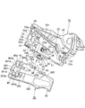
図5及び図6に示すように、カバー18における車内側を向く側面の下部には、車内方向に突出し、かつ後下がりに傾斜する庇状の上部雨水誘導突部28と下部雨水誘導突部29が形成されている。この上部雨水誘導突部28と下部雨水誘導突部29は、カバー18の表面を伝って流れ落ちる雨水を後下方に誘導し、後述するケーブル連結領域部181に向かって流れるのを防止するためのものである。
カバー18における下部雨水誘導突部29の下方には、第1、第2ボーデンケーブル19、21を、それぞれロッキングレバー20とインサイドレバー22に連結するためのケーブル連結領域部181が、後下がりに傾斜するようにして形成されている。このケーブル連結領域部181は、下部雨水誘導突部29とカバー18の前縁に沿って設けられ、車内側へ突出する斜め上下方向の前壁部30と、カバー18の後下がりに傾斜する下縁に沿って設けられ、車内側へ突出する前後方向の下壁部31とにより囲まれて形成されている。
ケーブル連結領域部181には、前壁部30と対向し、車内方向に突出する上下方向の中間壁部32と、この中間壁部32のやや後方においてそれと対向し、車内方向に突出する上下方向のケーブル保持部33と、ケーシング15の操作機構収容部16の内部に連通するように開口し、ロッキングレバー20の下端部の回動軌跡に沿う形状の長孔34と、同じく操作機構収容部16の内部に連通し、インサイドレバー22の下端部がケーブル連結領域部181側に突出するとともに、その下端部の回動軌跡に沿う形状の切欠き35とが形成されている。前壁部30には、第1、第2ボーデンケーブル19、21のアウタチューブ191、211の端部がそれぞれ嵌合される2個の嵌合溝30a、30aが形成され、中間壁部32には、第1、第2ボーデンケーブル19、21の大径端部192、212がそれぞれ嵌合される2個の嵌合溝32a、32aが形成されている。また、ケーブル保持部33には、第1、第2ボーデンケーブル19、21の大径端部192、212の先端部に形成されたそれぞれの環状溝を嵌合することにより、両大径端部192、212を軸方向に移動不能に保持する保持溝33a、33aが形成されている。
第1ボーデンケーブル19におけるインナケーブル193の端末部の球形をなす連結部193aは、ロッキングレバー20の下端部に形成された車内側が開口する半球面状の凹部20aに、長孔34を介して嵌合されている。また、第2ボーデンケーブル21におけるインナケーブル213の端末部の軸状をなす連結部213aは、インサイドレバー22における切欠き35より突出する下端部に形成された嵌合孔22aに嵌合されている。両連結部193a、213aは、ケーブル連結領域部181を閉塞する後述の補助カバー36により、凹部20a及び嵌合孔22aから離脱するのが防止される。なお、上記ロッキングレバー20の凹部20aとインサイドレバー22の嵌合孔22aは、被連結部に相当する。
ケーブル連結領域部181は、第1、第2ボーデンケーブル19、21をそれぞれロッキングレバー20とインサイドレバー22に連結した後、カバー18と別体をなす合成樹脂製の補助カバー36により閉塞されるようになっている。
図3に示すように、補助カバー36は、ケーブル連結領域部181とほぼ同形をなし、前縁には、ケーブル連結領域部181を閉塞した状態において、カバー18の前壁部30の前面と接触する側壁部361が、ケーブル連結領域部181方向に向かって突出されている。また、補助カバー36には、ケーブル連結領域部181を閉塞した状態において、カバー18の下部雨水誘導突部29と近接する下方において車内側の側面に当接可能な上壁部362が、側壁部361と連続するようにして、ケーブル連結領域部181方向に向かって突出されている。側壁部361には、ケーブル連結領域部181を閉塞した状態において、第1、第2ボーデンケーブル19、21のアウタチューブ191、211を車内側から押さえて保持可能な押え溝361a、361aが形成されている。
さらに、補助カバー36の裏面(ケーブル連結領域部181を閉塞した状態において、それと対向する面)の前部には、ケーブル連結領域部181を閉塞した状態において、カバー18の前壁部30と中間壁部32間に位置する第1中間側壁部363と、カバー18の中間壁部32とケーブル保持部33間に位置する第2中間側壁部364とが、それぞれケーブル連結領域部181方向に向かって突出されている。第1中間側壁部363と第2中間側壁部364には、ケーブル連結領域部181を閉塞した状態において、第1、第2ボーデンケーブル19、21の大径端部192、212を車内側から押えて保持可能な上下2個ずつの押え溝363a、364aが形成されている。
図3~図7に示すように、補助カバー36の上端面(ケーブル連結領域部181を閉塞した状態においては下端面)365の前後方向の中央部には、上部が裏面方向に屈曲された前後1対の突片37、37が上向きに一体的に突設され、両突片37の先端部の対向面間には、前後方向を向くヒンジ軸38が、上端面365と平行に離間するようにして、両突片37と一体的に設けられている。
ヒンジ軸38の長手方向と直交する横断面形状は、ほぼ楕円形とされ、その長軸方向である上下の外周面には、互いに平行をなす平坦部38a、38aが、長手方向(前後方向)に沿って形成されている。なお、この実施形態では、上下の平坦部38a、38a間の寸法を、カバー18に設けられた後述する上下1対の弾性保持片42、42の対向面間の寸法より僅かに小としてある。
補助カバー36の上端面365における前後の突片37、37間の中央部には、補助カバー36と共にヒンジ軸38回りに回転することにより、カバー18に設けられた後述するストッパ部43を乗り越えてその反対側に移動可能な先細り形状の被ストッパ部39が、上向きに(ケーブル連結領域部181を閉塞した状態においては下向きに)突設されている。
図3及び図7の断面図に示すように、ケーシング15の一部をなしているカバー18におけるケーブル連結領域部181の下端の前後方向の中央部には、方形の開口40を有する、補助カバー36を取付けるための板状の取付部41が下向きに突設され、この取付部41の車内側の面には、補助カバー36のヒンジ軸38を回転可能に保持する上下1対の弾性保持片42、42が、開口40を挟んで対向するように、車内方向に向かって一体的に突設されている。
上下の弾性保持片42の先端部には、互いに対向する爪部42a、42aが内向きに突設されている。両爪部42aの対向面間の寸法は、両弾性保持片42間に嵌合されたヒンジ軸38が離脱しないように、ヒンジ軸38の短軸方向の最小外径寸法よりも若干小とされている。下方の弾性保持片42の車外側の端部には、図9に示すように、被ストッパ部39が上方より当接することにより、補助カバー36を第1開放位置に停止させて仮保持するためのストッパ部43が、被ストッパ部39の先端部の回転軌跡上に位置するようにして一体的に連設されている(詳細な説明は後述する)。
カバー18におけるケーブル連結領域部181の下端には、補助カバー36が前後方向に移動するのを規制する前後動規制片44、44が、取付部41を挟んで対向するように下向きに突設されている。この両前後動規制片44の対向面間の寸法は、補助カバー36における前後の突片37、37の外側面の離間寸法よりも僅かに大とされ、上下の弾性保持片42間にヒンジ軸38を嵌合した際に、前後の突片37の外側面が1対の前後動規制片44の対向面に近接または接触することにより、カバー18に対し補助カバー36が前後方向に移動するのが防止されるようになっている(図5、図6参照)。
図3に示すように、補助カバー36の上端面365と近接する裏面の前端部と後部には、ケーブル連結領域部181を閉塞した状態では車外方向を向き、かつ先端部に係合爪45a、45aを有する係合片45、45が突設されている。
また、補助カバー36の上壁部362における前後両端部の下面(ケーブル連結領域部181を閉塞した状態においては上面)には、係合爪部46、46が突設されている。
また、補助カバー36の上壁部362における前後両端部の下面(ケーブル連結領域部181を閉塞した状態においては上面)には、係合爪部46、46が突設されている。
上記前後の両係合片45は、ケーブル連結領域部181を補助カバー36により閉塞した際に、カバー18におけるケーブル連結領域部181の下端部の前端部と後部に設けられた係合孔47、47に嵌合されて、それらの奥端の開口縁に係合爪45a、45aが係合するようになっている。
また、上記の両係合爪部46は、ケーブル連結領域部181を補助カバー36により閉塞した際に、カバー18における下部雨水誘導突部29の下面の前後両端部に設けられた被係合爪部48、48に係合するようになっている。これら前後2個ずつの係合45と係合爪部46により、補助カバー36の4箇所が、カバー18のケーブル連結領域部181に、がたなく安定的に固定される。
また、上記の両係合爪部46は、ケーブル連結領域部181を補助カバー36により閉塞した際に、カバー18における下部雨水誘導突部29の下面の前後両端部に設けられた被係合爪部48、48に係合するようになっている。これら前後2個ずつの係合45と係合爪部46により、補助カバー36の4箇所が、カバー18のケーブル連結領域部181に、がたなく安定的に固定される。
補助カバー36をカバー18に取付けるには、カバー18の上下の弾性保持片42間に、補助カバー36に設けたヒンジ軸38を、両弾性保持片42を拡開方向に弾性変形させながら嵌合する。この際、ヒンジ軸38を長軸方向から嵌合すると、両弾性保持片42の弾性変形量が小さくなるので、嵌合し易い。
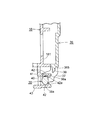
補助カバー36は、図6及び図7に示すように、ケーブル連結領域部181を閉塞する閉塞位置と、図5及び図9に示すように、閉塞位置から例えばほぼ210度開いた位置で仮保持される第1開放位置に、ヒンジ軸38を中心として上下方向に回転することができる。
補助カバー36を図9に示す第1開放位置に仮保持する場合は、ヒンジ軸38を取付部41の開口40側(車外方向)に移動させながら開方向に回転させる。すると、図8に示すように、カバー18に設けたストッパ部43の先端部が、補助カバー36に設けた被ストッパ部39の先端により上方に弾性変形させられ、図9に示すように、被ストッパ部39がストッパ部43の先端を乗り越えてその上方に移動する。これにより、被ストッパ部39の下面がストッパ部43の先端部の上面に当接し、補助カバー36の閉方向の回転が阻止されることにより、補助カバー36は第1開放位置に確実に停止して仮保持される。
第1開放位置に停止している補助カバー36を閉方向に回転させると、上記と反対に、ストッパ部43が被ストッパ部39により下向きに弾性変形させられるので、補助カバー36を閉塞位置方向まで支障なく回転させることができる。なお、ヒンジ軸38を開口40側に大きく移動させうるようにして、被ストッパ部39がストッパ部43の先端を乗り越えるようにすれば、ストッパ部43を被ストッパ部39により弾性変形させることなく、被ストッパ部39の下面をストッパ部43の上面に当接させて、補助カバー36を第1開放位置に仮保持することも可能である。
このように、補助カバー36を第1開放位置に仮保持させうるようにすると、補助カバー36が閉方向に回転するのが確実に阻止されるので、ドアラッチ装置をドアD内に組み付けたり、ケーブル連結領域部181に第1、第2ボーデンケーブル19、21を組付けたり、インナケーブル193、213をロッキングレバー20及びインサイドレバー22に連結したりする際に、補助カバー36が妄りに回転して邪魔になるというおそれがなく、それらの作業性を向上させることができる。
以上説明したように、上記第1の実施形態に係るドアラッチ装置1においては、補助カバー36に設けたヒンジ軸38を、カバー18に設けた1対の弾性保持片42、42間に回転可能に嵌合し、補助カバー36を開方向へ回転させた場合に、被ストッパ部39がストッパ部43の先端部を乗り越えて反対側に移動し、補助カバー36の閉方向への回転を阻止して補助カバー36を第1開放位置に仮保持しうるようにしたので、補助カバー36を第1開放位置に仮保持する手段の構成が、従来のドアラッチ装置の仮止め手段に比して簡単であり、ケーシング15や補助カバー36を成形する際のコストが低減される。
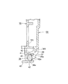
図10及び図11は、第2の実施形態に係るドアラッチ装置の補助カバー36取付部の断面図を示す。この第2の実施形態では、ヒンジ軸38に形成された上下の平坦部38a、38aを回転規制部として、補助カバー36を、ほぼ180度開放された第2開放位置に仮保持しうるようにしたものである。
すなわち、この第2の実施形態においては、上下の弾性保持片42、42の対向面間の寸法を、ヒンジ軸38における上下の平坦部(回転規制部)38a、38a間の上下寸法よりも所要寸法小とし、補助カバー36が、ケーブル連結領域部181を閉塞する閉塞位置、及び180度回転してケーブル連結領域部181を開放する第2開放位置にあるとき、両弾性保持片42間に嵌合されたヒンジ軸38の上下の平坦部38a、38aに、両弾性保持片42の対向面が弾性的に圧接しうるようにしたものである。
すなわち、この第2の実施形態においては、上下の弾性保持片42、42の対向面間の寸法を、ヒンジ軸38における上下の平坦部(回転規制部)38a、38a間の上下寸法よりも所要寸法小とし、補助カバー36が、ケーブル連結領域部181を閉塞する閉塞位置、及び180度回転してケーブル連結領域部181を開放する第2開放位置にあるとき、両弾性保持片42間に嵌合されたヒンジ軸38の上下の平坦部38a、38aに、両弾性保持片42の対向面が弾性的に圧接しうるようにしたものである。
ヒンジ軸38の断面形状をほぼ楕円形とし、その長軸方向の外周面に回転規制部としての平坦部38aを設けると、補助カバー36が閉塞位置及び第2開放位置にあるとき、両弾性保持片42の拡開方向への弾性変形量が最大となり、その反力も最大となる。その結果、上下の平坦部38aに両弾性保持片42が強く圧接するため、ヒンジ軸38と両弾性保持片42との相対回転が規制されて、補助カバー36を第2開放位置に停止させて仮保持する保持力が大となる。また、補助カバー36が上記閉塞位置から第2開放位置方向へ、またはその逆方向へ回転する際には、両弾性保持片42の弾性変形量が徐々に小さくなり、ヒンジ軸38に加わる押圧力も小となるので、補助カバー36を抵抗なく回転させることができる。
第2の実施形態に係るドアラッチ装置においては、閉塞位置にある補助カバー36を開方向へ180度回転させると、上述したように、カバー18の上下の弾性保持片42の対向面が、ヒンジ軸38の上下の平坦部38aに弾性的に圧接し、ヒンジ軸38と両弾性保持片42との相対回転が規制されて、補助カバー36の開閉方向への回転も規制されることにより、補助カバー36は、180度開いた第2開放位置に停止して仮保持される。なお、図11に示すように、補助カバー36が第2開放位置に停止しているときには、被ストッパ部39の先端(上端)が、ストッパ部43の下面に近接または当接するので、補助カバー36が第2開放位置を超えて回転することはない。また、この第2の実施形態においては、補助カバー36を第2開放位置を超えて回転させれば、上記第1の実施形態と同様に、補助カバー36を第1開放位置に仮保持することも可能である。
第2の実施形態に係るドアラッチ装置においても、補助カバー36に、上下の外周面に互いに平行をなす平坦部(回転規制部)38a、38aを有するほぼ楕円形のヒンジ軸38を設け、このヒンジ軸38を、カバー18側に設けた上下1対の弾性保持片42、42間に嵌合して、上下の回転規制部38aに両弾性保持片42を弾性的に圧接させるだけの簡単な構成で、補助カバー36を、180度開いた第2開放位置に停止させて仮保持しうるので、補助カバー36を開放位置に仮保持する手段の構成が、従来のドアラッチ装置の仮止め手段に比して簡単であり、カバー18や補助カバー36を成形する際のコストが低減される。
また、補助カバー36を180度開いた第2開放位置に停止させて仮保持しうるので、上記第1の実施形態と同様に、ドアラッチ装置をドアD内に組み付ける際の組付作業性や、ケーブル連結領域部181への第1、第2ボーデンケーブル19、21の組付け作業性等を向上させることができる。
以上、本発明の実施形態について説明したが、本発明の要旨を逸脱しない範囲内で、本実施形態に対して、例えば次のような種々の変形や変更を施すことが可能である。
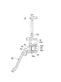
上記実施形態では、補助カバー36側にヒンジ軸38を設け、このヒンジ軸38を、カバー18側に設けた上下1対の弾性保持片42間に嵌合しているが、それらの嵌合関係を、図12に示すように逆としてもよい。すなわち、例えばカバー18の下面に、補助カバー36取付用の互いに対向する1対の取付部49を下向きに突設し、両取付部49の対向面間に、上記第1の実施形態と同様のヒンジ軸38を設け、このヒンジ軸38に、補助カバー36の下面に突設された、上記実施形態とは逆向きの上下1対の弾性保持片42、42を、車内側より回転自在に嵌合する。また、例えば補助カバー36の下端部(閉塞状態では上端部)とカバー18の下面とに、それぞれ、上記実施形態と同様の被ストッパ部39とストッパ部43を設け、補助カバー36を180度を超える位置まで開方向へ回転させたとき、被ストッパ部39がストッパ部43を乗り越えるようにすれば、図13に示すように、補助カバー36を、上記第1の実施形態と同様に、第1開放位置に停止させて仮保持することができる。
上記実施形態では、補助カバー36側にヒンジ軸38を設け、このヒンジ軸38を、カバー18側に設けた上下1対の弾性保持片42間に嵌合しているが、それらの嵌合関係を、図12に示すように逆としてもよい。すなわち、例えばカバー18の下面に、補助カバー36取付用の互いに対向する1対の取付部49を下向きに突設し、両取付部49の対向面間に、上記第1の実施形態と同様のヒンジ軸38を設け、このヒンジ軸38に、補助カバー36の下面に突設された、上記実施形態とは逆向きの上下1対の弾性保持片42、42を、車内側より回転自在に嵌合する。また、例えば補助カバー36の下端部(閉塞状態では上端部)とカバー18の下面とに、それぞれ、上記実施形態と同様の被ストッパ部39とストッパ部43を設け、補助カバー36を180度を超える位置まで開方向へ回転させたとき、被ストッパ部39がストッパ部43を乗り越えるようにすれば、図13に示すように、補助カバー36を、上記第1の実施形態と同様に、第1開放位置に停止させて仮保持することができる。
上記第2の実施形態では、ヒンジ軸38における長軸方向の上下両面に平坦部(回転規制部)38aを設けているが、上下いずれか一方の平坦部38aを省略して実施することもある。このようにしても、補助カバー36を180度回転させたとき、いずれか一方の平坦部38aが、上下いずれか一方の弾性保持片42に弾性的に圧接するので、補助カバー36を第2開放位置に仮保持することができる。なお、上下いずれか一方の平坦部38aを省略した場合には、弾性保持片42による補助カバー36の仮保持力を大とするために、平坦部38aの前後寸法(幅寸法)を、上記実施形態よりも大とするのがよい。
上記実施形態では、ヒンジ軸38と弾性保持片42を、それぞれ補助カバー36とカバー18の前後方向の中央部に設けているが、それらを、例えば、補助カバー36とカバー18における前後方向の両端部の2箇所に設けてもよい。
ヒンジ軸38の断面形状を円形とし、その上下両面、またはいずれか一方の面に、平坦部38aを設けてもよい。
1 ドアラッチ装置
2 噛合ユニット
3 操作ユニット
4 ボディ
5 ボルト
6 カバープレート
7 噛合機構
8 ストライカ
9 ストライカ進入溝
10a、10b、10c 雌ねじ孔
11 枢軸
12 ラッチ
13 枢軸
14 ラチェット
15 ケーシング
16 操作機構収容部
17 ボディ収容部
18 カバー
19 第1ボーデンケーブル(操作力伝達部材)
20 ロッキングレバー(操作レバー)
20a 凹部(被連結部)
21 第2ボーデンケーブル(操作力伝達部材)
22 インサイドレバー(操作レバー)
22a 嵌合孔(被連結部)
23 支持軸
24 アウトサイドレバー
25 バックプレート
26 雌ねじ孔
27 ボルト
28 上部雨水誘導突部
29 下部雨水誘導突部
30 前壁部
30a 嵌合溝
31 下壁部
32 中間壁部
32a 嵌合溝
33 ケーブル保持部
33a 保持溝
34 長孔(開口部)
35 切欠き(開口部)
36 補助カバー
37 突片
38 ヒンジ軸
38a 平坦部(回転規制部)
39 被ストッパ部
40 開口
41 取付部
42 弾性保持片
42a 爪部
43 ストッパ部
44 前後動規制片
45 係合片
45a 係合爪
46 係合爪部
47 係合孔
48 被係合爪部
49 取付部
151 第1ケーシング
152 第2ケーシング
181 ケーブル連結領域部
191、211 アウタチューブ
192、212 大径端部
193、213 インナケーブル
193a、213a 連結部
361 側壁部
361a 押え溝
362 上壁部
363 第1中間側壁部
364 第2中間側壁部
363a、364a 押え溝
365 上端面
D ドア
D1 インナパネル
Claims (4)
- ケーシングと、
前記ケーシング内に設けられ、操作装置の操作力を伝達可能な操作力伝達部材の端末である連結部を、前記ケーシングに設けた開口部を介して連結可能な被連結部を有する操作レバーと、
前記ケーシングとは別体に形成され、前記操作レバーの前記被連結部に前記操作力伝達部材の前記連結部を連結した部分を含む連結領域部を閉塞可能な補助カバーとを備える車両用ドアラッチ装置において、
前記ケーシングと前記補助カバーとのいずれか一方にヒンジ軸を、同じく他方に、互いに対向する1対の弾性保持片をそれぞれ設け、
前記両弾性保持片間に、前記ヒンジ軸を、前記補助カバーが前記連結領域部を閉塞する閉塞位置及び前記連結領域部を開放する開放位置に回転しうるように嵌合し、
前記補助カバーに被ストッパ部を設けるとともに、前記ケーシングに、前記被ストッパ部が当接可能なストッパ部を設け、前記補助カバーを開方向へ回転させた場合に、前記被ストッパ部が前記ストッパ部の先端部を乗り越えて反対側に移動し、前記補助カバーの閉方向への回転を阻止することにより、前記補助カバーを前記開放位置に仮保持しうるようにしたことを特徴とする車両用ドアラッチ装置。 - 前記ヒンジ軸の外周面に、前記補助カバーを開方向へ回転させた場合に、前記両弾性保持片の対向面の少なくともいずれか一方に弾性的に面接触し、前記ヒンジ軸と前記弾性保持片との相対回転を規制することにより、前記補助カバーを第2開放位置に仮保持可能な回転規制部を設けたことを特徴とする請求項1に記載の車両用ドアラッチ装置。
- 前記ヒンジ軸の横断面形状をほぼ楕円形とし、その長軸方向の外周面に前記回転規制部を設けたことを特徴とする請求項2に記載の車両用ドアラッチ装置。
- 前記ヒンジ軸における長軸方向の両外周面に、前記回転規制部を、互いに平行をなすように設け、前記両回転規制部が前記両弾性保持片の対向面に弾性的に面接触することにより、前記補助カバーがほぼ180度開いた第2開放位置に仮保持されるようにしたことを特徴とする請求項3に記載の車両用ドアラッチ装置。
Priority Applications (3)
| Application Number | Priority Date | Filing Date | Title |
|---|---|---|---|
| CN201580058656.1A CN107075886B (zh) | 2014-10-28 | 2015-02-24 | 车门闩锁装置 |
| EP15853816.5A EP3214242B1 (en) | 2014-10-28 | 2015-02-24 | Vehicle door latching device |
| US15/521,158 US10526823B2 (en) | 2014-10-28 | 2015-02-24 | Vehicle door latching device |
Applications Claiming Priority (2)
| Application Number | Priority Date | Filing Date | Title |
|---|---|---|---|
| JP2014219535A JP6379438B2 (ja) | 2014-10-28 | 2014-10-28 | 車両用ドアラッチ装置 |
| JP2014-219535 | 2014-10-28 |
Publications (1)
| Publication Number | Publication Date |
|---|---|
| WO2016067645A1 true WO2016067645A1 (ja) | 2016-05-06 |
Family
ID=55857005
Family Applications (1)
| Application Number | Title | Priority Date | Filing Date |
|---|---|---|---|
| PCT/JP2015/055301 Ceased WO2016067645A1 (ja) | 2014-10-28 | 2015-02-24 | 車両用ドアラッチ装置 |
Country Status (5)
| Country | Link |
|---|---|
| US (1) | US10526823B2 (ja) |
| EP (1) | EP3214242B1 (ja) |
| JP (1) | JP6379438B2 (ja) |
| CN (1) | CN107075886B (ja) |
| WO (1) | WO2016067645A1 (ja) |
Families Citing this family (8)
| Publication number | Priority date | Publication date | Assignee | Title |
|---|---|---|---|---|
| JP6379438B2 (ja) * | 2014-10-28 | 2018-08-29 | 三井金属アクト株式会社 | 車両用ドアラッチ装置 |
| US10941592B2 (en) * | 2015-05-21 | 2021-03-09 | Magna Closures Inc. | Latch with double actuation and method of construction thereof |
| CN107620529B (zh) | 2016-07-15 | 2020-12-15 | 株式会社安成 | 车辆用门锁装置 |
| JP6627729B2 (ja) * | 2016-11-25 | 2020-01-08 | 株式会社アンセイ | 車両用ドアロック装置 |
| JP6627920B2 (ja) * | 2018-06-26 | 2020-01-08 | 株式会社アンセイ | 車両用ドアロック装置 |
| JP6710734B2 (ja) * | 2018-10-02 | 2020-06-17 | アイシン精機株式会社 | 車両用ドアロック装置 |
| DE102021105156A1 (de) * | 2021-03-03 | 2022-09-08 | Brose Schließsysteme GmbH & Co. Kommanditgesellschaft | Komponentengehäuse für eine Kraftfahrzeugschließkomponente |
| JP7827980B2 (ja) | 2022-06-06 | 2026-03-11 | 株式会社アンセイ | 車両用開閉体のロック装置 |
Citations (4)
| Publication number | Priority date | Publication date | Assignee | Title |
|---|---|---|---|---|
| JP4050609B2 (ja) * | 2002-12-24 | 2008-02-20 | 三井金属鉱業株式会社 | ドアラッチ装置 |
| JP2013113008A (ja) * | 2011-11-29 | 2013-06-10 | Yuhshin Co Ltd | ドアロック装置 |
| JP2013256185A (ja) * | 2012-06-12 | 2013-12-26 | Daihatsu Motor Co Ltd | 車両のドアロック |
| JP5509377B1 (ja) * | 2013-08-09 | 2014-06-04 | アイシン精機株式会社 | 車両用ドアロック装置 |
Family Cites Families (9)
| Publication number | Priority date | Publication date | Assignee | Title |
|---|---|---|---|---|
| US5048715A (en) * | 1989-09-07 | 1991-09-17 | Dart Industries, Inc. | Closure assembly with hinged cover |
| US6733052B2 (en) * | 2000-12-14 | 2004-05-11 | Delphi Technologies, Inc. | Power operated vehicle door latch |
| WO2011023262A2 (de) * | 2009-07-15 | 2011-03-03 | Johnson Controls Gmbh | Mechatronisches entriegelungsmittel |
| JP5447860B2 (ja) * | 2010-03-24 | 2014-03-19 | アイシン精機株式会社 | 車両用ドアロック装置 |
| JP5668468B2 (ja) * | 2010-12-28 | 2015-02-12 | アイシン精機株式会社 | 車両用ドアロック装置 |
| JP5495163B2 (ja) * | 2011-03-02 | 2014-05-21 | 三井金属アクト株式会社 | 自動車用ドアロック装置 |
| JP5437309B2 (ja) * | 2011-04-22 | 2014-03-12 | アイシン精機株式会社 | 回転レバーの位置保持装置および該回転レバーの位置保持装置を備える車両用ドアロック装置 |
| JP5966813B2 (ja) * | 2012-09-24 | 2016-08-10 | アイシン精機株式会社 | 車両用ドアロック装置 |
| JP6379438B2 (ja) * | 2014-10-28 | 2018-08-29 | 三井金属アクト株式会社 | 車両用ドアラッチ装置 |
-
2014
- 2014-10-28 JP JP2014219535A patent/JP6379438B2/ja active Active
-
2015
- 2015-02-24 WO PCT/JP2015/055301 patent/WO2016067645A1/ja not_active Ceased
- 2015-02-24 US US15/521,158 patent/US10526823B2/en active Active
- 2015-02-24 EP EP15853816.5A patent/EP3214242B1/en active Active
- 2015-02-24 CN CN201580058656.1A patent/CN107075886B/zh active Active
Patent Citations (4)
| Publication number | Priority date | Publication date | Assignee | Title |
|---|---|---|---|---|
| JP4050609B2 (ja) * | 2002-12-24 | 2008-02-20 | 三井金属鉱業株式会社 | ドアラッチ装置 |
| JP2013113008A (ja) * | 2011-11-29 | 2013-06-10 | Yuhshin Co Ltd | ドアロック装置 |
| JP2013256185A (ja) * | 2012-06-12 | 2013-12-26 | Daihatsu Motor Co Ltd | 車両のドアロック |
| JP5509377B1 (ja) * | 2013-08-09 | 2014-06-04 | アイシン精機株式会社 | 車両用ドアロック装置 |
Non-Patent Citations (1)
| Title |
|---|
| See also references of EP3214242A4 * |
Also Published As
| Publication number | Publication date |
|---|---|
| JP6379438B2 (ja) | 2018-08-29 |
| US20170314303A1 (en) | 2017-11-02 |
| EP3214242A4 (en) | 2018-06-06 |
| US10526823B2 (en) | 2020-01-07 |
| CN107075886A (zh) | 2017-08-18 |
| EP3214242B1 (en) | 2020-05-20 |
| CN107075886B (zh) | 2019-12-13 |
| JP2016084661A (ja) | 2016-05-19 |
| EP3214242A1 (en) | 2017-09-06 |
Similar Documents
| Publication | Publication Date | Title |
|---|---|---|
| JP6379438B2 (ja) | 車両用ドアラッチ装置 | |
| JP6368954B2 (ja) | 車両用ドアラッチ装置 | |
| JP4765123B2 (ja) | 自動車用ドアラッチ装置 | |
| WO2015136775A1 (ja) | 車両用ドアラッチ装置 | |
| US7302818B2 (en) | Apparatus for locking and unlocking vehicle door | |
| WO2016143082A1 (ja) | ドアラッチ装置 | |
| US10597908B2 (en) | Vehicle door latch device | |
| WO2017130362A1 (ja) | 車両用ドアラッチ装置 | |
| JP2018091109A (ja) | リッド開閉装置 | |
| JP5005047B2 (ja) | 車両用ドアラッチ装置 | |
| JP6543837B2 (ja) | 車両用ドアラッチ装置 | |
| US10471810B2 (en) | Vehicle door lock device | |
| JP2015137509A (ja) | 車両用ドアラッチ装置 | |
| JP2007153155A (ja) | リッド構造 | |
| JP2017150173A (ja) | チャイルドロック機構付きドアラッチ装置及びチャイルドロック機構の組付方法 | |
| WO2020049856A1 (ja) | 車両用リッドロック装置 | |
| JP6492349B2 (ja) | 車両用ドアラッチ装置 | |
| JP6347090B2 (ja) | 車両ドアラッチ装置 | |
| JP5938840B2 (ja) | 車両用ドアラッチ装置 | |
| JP4801812B2 (ja) | 車両用シリンダ錠装置 | |
| JP2014001568A (ja) | 車両用ドアのラッチ解除操作装置 | |
| JP2012112242A (ja) | 車両用ドアラッチ装置におけるアクチュエータ | |
| JP2006016884A (ja) | キーシリンダキャップの取付構造 | |
| US20110041571A1 (en) | Vehicle door locking system | |
| JP2011127324A (ja) | 車両用ドアラッチ装置 |
Legal Events
| Date | Code | Title | Description |
|---|---|---|---|
| 121 | Ep: the epo has been informed by wipo that ep was designated in this application |
Ref document number: 15853816 Country of ref document: EP Kind code of ref document: A1 |
|
| REEP | Request for entry into the european phase |
Ref document number: 2015853816 Country of ref document: EP |
|
| WWE | Wipo information: entry into national phase |
Ref document number: 15521158 Country of ref document: US |
|
| NENP | Non-entry into the national phase |
Ref country code: DE |