WO2016072003A1 - Convertisseur de puissance et procédé de commande de convertisseur de puissance - Google Patents
Convertisseur de puissance et procédé de commande de convertisseur de puissance Download PDFInfo
- Publication number
- WO2016072003A1 WO2016072003A1 PCT/JP2014/079519 JP2014079519W WO2016072003A1 WO 2016072003 A1 WO2016072003 A1 WO 2016072003A1 JP 2014079519 W JP2014079519 W JP 2014079519W WO 2016072003 A1 WO2016072003 A1 WO 2016072003A1
- Authority
- WO
- WIPO (PCT)
- Prior art keywords
- braking
- current
- voltage
- power
- power converter
- Prior art date
- Legal status (The legal status is an assumption and is not a legal conclusion. Google has not performed a legal analysis and makes no representation as to the accuracy of the status listed.)
- Ceased
Links
Images






Classifications
-
- H—ELECTRICITY
- H02—GENERATION; CONVERSION OR DISTRIBUTION OF ELECTRIC POWER
- H02P—CONTROL OR REGULATION OF ELECTRIC MOTORS, ELECTRIC GENERATORS OR DYNAMO-ELECTRIC CONVERTERS; CONTROLLING TRANSFORMERS, REACTORS OR CHOKE COILS
- H02P6/00—Arrangements for controlling synchronous motors or other dynamo-electric motors using electronic commutation dependent on the rotor position; Electronic commutators therefor
- H02P6/24—Arrangements for stopping
-
- H—ELECTRICITY
- H02—GENERATION; CONVERSION OR DISTRIBUTION OF ELECTRIC POWER
- H02P—CONTROL OR REGULATION OF ELECTRIC MOTORS, ELECTRIC GENERATORS OR DYNAMO-ELECTRIC CONVERTERS; CONTROLLING TRANSFORMERS, REACTORS OR CHOKE COILS
- H02P3/00—Arrangements for stopping or slowing electric motors, generators, or dynamo-electric converters
- H02P3/06—Arrangements for stopping or slowing electric motors, generators, or dynamo-electric converters for stopping or slowing an individual dynamo-electric motor or dynamo-electric converter
- H02P3/18—Arrangements for stopping or slowing electric motors, generators, or dynamo-electric converters for stopping or slowing an individual dynamo-electric motor or dynamo-electric converter for stopping or slowing an AC motor
Definitions
- the present invention relates to a power converter and a method for controlling the power converter.
- Patent Document 1 JP 2013-188000 A
- Patent Document 2 JP 2000-217388 A
- the gazette states that “While the vehicle decelerates from the rotational speed at the start of deceleration to the braking system switching speed, braking is performed by the short brake system with low deceleration efficiency but no heat generation, from the braking system switching speed to the deceleration target speed.
- the braking is performed by the reverse braking system with a high deceleration rate although heat is generated in the transistors Q1 to Q6.
- the short brake period and the reverse brake period are not necessarily the same length period, but the first half of the braking period
- Patent Document 1 by applying a voltage between the terminals of the motor 3 with a phase delayed from the phase of the induced voltage, torque is generated in a direction that hinders the rotation of the motor 3, and the rotation of the motor 3 is prevented.
- a method of switching from delayed phase control for braking to short-circuit braking for short-circuiting between terminals of the motor 3 at low speed short-circuit braking is performed using the voltage generated by the magnet motor at a low speed. Therefore, when the rotation speed decreases and the generated voltage decreases, the generated voltage of the magnet motor is less than the voltage drop of the elements of the power converter. When it becomes low, the electric current which contributes to braking force will become extremely small, and there exists a subject that braking force will fall extremely.
- Patent Document 2 braking is executed by a short brake method in which the field coils L1 to L3 are at the same potential, and when the motor falls below a predetermined speed, the field coils L1 to L3 are excited in the reverse direction.
- a method of switching to the reverse brake system is shown. In this method, since a reverse voltage having the same period as the phase of the induced voltage is applied, the induced voltage becomes small in the low speed region, and when a voltage in the reverse direction is applied, the voltage may cause reverse rotation. There is a problem of being.
- a motor and an electric motor are synonymous, and an inverter and a power converter are synonymous.
- an object of the present invention is to provide a power conversion device that quickly brakes an electric motor to which a load having a large inertia is connected without reversing, and a control method for the power conversion device.
- the present invention controls an AC converter that converts DC power into desired AC power, a current detector that detects a current flowing through the AC converter, and an output of the AC converter. And a control unit that performs the AC conversion under the condition that the AC motor connected to the power conversion device does not apply a rotational force to the AC motor while the AC motor is in a deceleration mode. It has an electric power converter characterized by performing alternating current braking which performs braking by flowing current.
- FIG. 3 is a flowchart of a braking command unit in the first embodiment. It is an example of the figure which showed the relationship between the braking force and braking current in Example 1.
- FIG. It is the figure which showed the example of the flow path of the braking force and electric current at the time of applying a short circuit braking. It is the figure which showed the example of the flow path of braking force and electric current at the time of applying an alternating current braking.
- 6 is a flowchart relating to control switching of a braking command unit according to the second embodiment. It is an example of the figure which showed the relationship of the braking current in Example 2.
- FIG. 1 It is an example of the figure which showed the relationship between the braking force and braking current in Example 1.
- 12 is a flowchart regarding end determination by time of an output control unit according to the third embodiment. It is the example of the figure which showed the mode of the braking in Example 3, and the relationship of time. 14 is a flowchart relating to end determination based on an average current of an output control unit according to a fourth embodiment. It is the example of the figure which showed the mode of the braking in Example 4, and the relationship of time.
- the deceleration mode is a mode in which the rotation speed of the AC motor decreases when the AC motor is stopped, and is a state where a command to decelerate the AC motor is given to the power converter.
- the deceleration mode includes operations such as DC braking and short-circuit braking in addition to the case where the power conversion device performs three-phase AC voltage output for deceleration.
- Short-circuit braking is to perform braking by, for example, turning on an element connected to the N line of the AC conversion unit 104 and short-circuiting the three lines of the AC motor.
- the direct current braking is performed by applying direct current in the phase direction determined by the alternating current motor. Since AC braking is characterized by applying an AC voltage, it is called AC braking in the present invention. In other words, AC braking is an operation in which braking is performed by applying a high-frequency AC voltage to the AC motor. The operation of AC braking is specifically shown in FIG.
- FIG. 1 is an example of a configuration diagram of the power conversion device according to the first, second, and third embodiments.
- the block diagram which the three-phase alternating current power supply 101 and the alternating current motor 105 were connected to the power converter device of a present Example is shown.
- the power conversion device includes a DC conversion unit 102, a smoothing capacitor 103, an AC conversion unit 104, a current detector 106, a control calculation unit 107, a current detection unit 108, an output control unit 110, a braking command unit 109, an output generation unit 111, and a storage.
- the three-phase AC power source 101 is, for example, a three-phase AC voltage supplied from an electric power company or an AC voltage supplied from a generator, and outputs it to the DC converter 102.
- the DC conversion unit 102 includes, for example, a DC conversion circuit including a diode and a DC conversion circuit using an IGBT and a flywheel diode, and converts an AC voltage input from the three-phase AC power source 101 into a DC voltage. Output to the smoothing capacitor 103.
- FIG. 1 shows a direct current conversion unit formed of a diode.
- the smoothing capacitor 103 smoothes the DC voltage input from the DC converter 102 and outputs the DC voltage to the AC converter 104.
- the smoothing capacitor 103 may be input with a DC voltage directly from the generator without passing through the DC converter 106.
- the AC conversion unit 104 is configured by an AC conversion circuit using, for example, an IGBT and a flywheel diode.
- the AC conversion unit 104 receives the DC voltage of the smoothing capacitor 103 as an input, and converts the DC voltage from the PWM by the PWM output waveform input from the drive unit 114. The voltage is converted to a voltage and output to the AC motor 105.
- AC motor 105 receives the PWM output output from AC converter 104 as an input and drives a load.
- a case of a synchronous motor will be described.
- the current detector 106 is composed of, for example, a Hall CT or a shunt resistor, detects a current flowing between the AC converter 104 and the AC motor 105, and outputs it to the current detector 108.
- the control calculation unit 107 includes, for example, a microcomputer, an ASIC, a memory, and the like.
- the control calculation unit 107 inputs a current signal of the current detector 106 and an operation command from the operation unit 113, performs various calculations, and outputs the calculation result to the operation unit 113 and the AC. Output to the converter 104.
- the current detection unit 108 receives the current data of each phase output from the current detector 106, converts the acquired alternating current value of each phase into an effective current value that is an effective value, and acquires each acquired phase.
- Each AC current value is averaged or converted to an AC average current value through a filter, the AC average current value is converted to an average effective current value that is an effective value, and each current data is output to the output control unit 110.
- the output control unit 110 receives the AC current value, effective current value, AC average current value and average effective current value of each phase from the current detection unit 108, and the braking command from the braking command unit 109 as an output.
- a command or an AC braking command is calculated and output to the output generation unit 111.
- the output control unit 110 calculates an output phase command and an output voltage command as an output command from the output frequency command, the acquired current and various motor constants.
- the output control unit 110 detects the rotation speed of the motor from the phase of the AC current of each phase input from the current detection unit 108 during AC braking and the phase change of the AC average current of each phase during AC braking. And used for AC braking start and stop operation determination.
- the braking command unit 109 includes a stop command output from the operation unit 113, an AC current value of each phase, an effective current value, an AC average current value and an average effective current value of each phase from the current detection unit 108, and a storage unit 112.
- the braking time stored in is input, the braking command is calculated, and the command is output to the output control unit 110.
- the output generation unit 111 receives the output command information output from the output control unit 110, generates PWM output waveform data, and outputs the PWM output waveform data to the drive unit 114.
- the storage unit 112 is composed of, for example, a magnetic disk, an optical disk, a flash memory, or an EEPROM, and stores various data from, for example, the operation unit 113 as input.
- the storage unit 112 also receives a data acquisition request from the output control unit 110 or the braking command unit 109 and outputs data corresponding to the acquisition request to each request source.
- the operation unit 113 has, for example, an output terminal unit that gives a signal to the outside, and receives the braking command information from the braking command unit 109 and outputs a signal to the connected external device. Further, the operation unit 113 has an input terminal unit for inputting an external signal, for example, and outputs a braking command to the braking command unit 109 when a signal is input to the input terminal unit.
- the drive unit 114 receives the PWM data output from the output generation unit 111 and outputs a PWM output waveform to each element of the AC conversion unit 104.
- FIG. 2 is a flowchart for instructing AC braking of the output control unit 110 in the first embodiment.
- the output control unit 110 outputs a command for driving the connected synchronous motor and simultaneously monitors the braking command input from the braking command unit 109 (S201).
- the output control unit 110 determines whether there is an AC braking command (S202). If there is no AC braking command permission signal, the output control unit 110 continues to issue a command to drive the synchronous motor, and if there is, outputs an AC braking command. The data is output to the generation unit 111 (S203).
- the output control unit 110 presets and monitors, for example, a current value that needs to be protected for abnormality of the power monitoring device, for example, whether the current effective value detected by the current detection unit 108 is abnormal (S204). If there is no abnormality, the AC braking command is continued, and if there is an abnormality, the output is interrupted and AC braking is restarted (S205).
- a threshold value indicating whether or not to restart may be stored in the storage unit 112 in advance, and the data may be read at the time of restarting to determine whether or not to restart. Further, the output control unit 110 obtains the rotation speed of the electric motor from the phase of the AC average current of each phase input from the current detection unit, and the obtained rotation frequency can be determined in advance as a stop frequency, for example, a start frequency of the power converter. It is determined whether or not the set value or a fixed value of low rotation of 0.1 Hz is below (S206). If not, AC braking is continued, and if it is below, it is determined that the rotation of the motor has stopped. AC braking is then terminated (S207). The power converter may be restarted or stopped after the AC braking is finished.
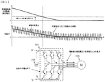
- FIG. 3 is an example of a diagram illustrating the relationship between the braking force and the braking current in the AC braking according to the first embodiment.
- FIG. 3 shows an example of current that flows during braking when an AC single shaft voltage is applied at a frequency higher than the shaft rotation frequency of the synchronous motor.
- the braking current includes a current (broken line) that flows due to the induced voltage generated by the rotation of the synchronous motor and a current (dotted line) that flows due to the AC voltage output of the power converter, and the combined current (solid line) actually enters the AC converter. Flowing.
- the upper part of FIG. 3 shows an enlarged view of part of the current during braking.
- the current (broken line) that flows due to the induced voltage generated by the rotation of the synchronous motor flows according to the relationship between the direction of the magnetic field generated by the magnet of the synchronous motor and the rotation direction of the magnet according to the general Fleming left-hand rule.
- the braking force due to the rotation of the magnet is directly opposite to the rotation direction of the magnet from the flowing current and the direction of the magnetic field generated by the magnet according to Fleming's left-hand rule.
- the current (dotted line) that flows due to the AC voltage output of the power converter is an AC current because the AC voltage is applied at a frequency higher than the rotational frequency of the synchronous motor.
- the output control unit 110 stores the maximum frequency for driving the synchronous motor in the storage unit 112.
- a cycle five times the machine time constant calculated from the inertia load or a frequency five times the maximum frequency is uniaxial.
- the frequency of the AC voltage to be applied may be based on the current frequency of the synchronous motor, as long as the synchronous motor is out of step and cannot continue to rotate. Since an AC voltage that does not generate a rotational force is applied at a frequency higher than the rotational frequency of the synchronous motor, for example, it is instantaneously synchronized between (A) and (E) or (B) and (D) in FIG.
- the force applied to the electric motor is offset and only the braking force due to the rotation of the motor shaft remains.
- the combined current of the braking currents corresponds to the alternating current of each phase, and only the braking current due to the rotation of the motor shaft, that is, the alternating current average can be detected by using averaging or a low-pass filter.
- the rotation speed of the electric motor can be detected from the cycle of the AC average current that is a braking current generated by the rotation of the motor shaft. Thereby, the power converter device performs braking of the synchronous motor.
- FIG. 4 is a diagram showing an example of the braking force and current flow path when short-circuit braking is applied.
- FIG. 4 shows that when the rotational speed of the synchronous motor decreases, the braking force decreases when the synchronous motor falls below a certain voltage level.
- short-circuit braking as shown in the lower part of FIG. 4, in order to short-circuit the three phases of the synchronous motor, for example, by switching the element of the AC conversion unit 104 so as to have the same potential as the N line of the smoothing capacitor 103, Current flows according to the voltage generated by the motor.
- the voltage generated by the synchronous motor becomes a voltage lower than the voltage drop determined by each element due to the voltage drop of each element of the AC conversion unit 104, such as an IGBT or a diode, Current stops flowing and braking force disappears.
- the inertia load is large, the synchronous motor continues to rotate due to inertia.
- AC braking is performed to avoid a decrease in braking force due to a voltage drop.
- FIG. 5 is a diagram showing an example of the braking force and current flow path when AC braking is applied.
- FIG. 5 shows a state in which the braking force follows the rotational speed of the synchronous motor even when the rotational speed of the synchronous motor decreases and falls below a certain voltage level.
- the DC voltage stored in the smoothing capacitor 103 is instantaneously applied. Therefore, the influence of the voltage drop of each element of the AC conversion unit 104, for example, IGBT or diode is reduced. Can continue to flow and maintain braking force.
- AC braking AC is applied at a high frequency that does not rotate the synchronous motor. Therefore, the braking force is canceled in the long term, and the actual braking force indicated by the solid line in FIG. 5 is applied during braking. It will be.
- the power conversion apparatus provides a mechanism capable of applying and stopping the braking force only in the direction of stopping until the stop, even when the inertia load is large, by the method as described above.
- FIG. 6 is a flowchart regarding control switching of the braking command unit in the second embodiment.
- the braking command unit 109 monitors the average effective current value input from the current detection unit 108 (S601), and determines whether the average effective current value is equal to or less than a preset AC braking threshold value (S602).
- the AC braking threshold is, for example, equivalent to 10% or more of the rated current of the synchronous motor from the resistance value and inductance of the synchronous motor and the voltage obtained by subtracting the voltage drop of the element of the AC converter 104 from the induced voltage generated by rotation. Is set to flow as an output. In this way, if the AC braking threshold is set, even if the rotational speed of the synchronous motor decreases and the induced voltage decreases, applying a high-frequency AC voltage instantaneously exceeds the voltage drop. Since voltage is applied to each element, current continues to flow. Since the alternating current generated by applying the alternating voltage includes a braking current due to rotation, the braking force can be maintained.
- FIG. 7 shows a state in which AC braking is started by the AC braking threshold.
- the alternating current which flows into the U phase of a synchronous motor is shown as an example of braking current.
- the current effective value calculated from the three-phase alternating current is shown. The current effective value is calculated using, for example, the following equations 1 and 2.
- Equation 1 shows that the U-phase current (Iu) and the W-phase current (Iw) among the three-phase AC currents are converted to current values set in the U-phase direction (I ⁇ ) and the axial direction (I ⁇ ) orthogonal to the U-phase. Represents a conversion.
- Equation 2 obtains the magnitude of the effective current Ioutput from the current in the biaxial direction calculated in Equation 1.
- the average effective current can be calculated by a method similar to the calculation of the effective current by replacing the alternating current of (Equation 1) and (Equation 2) with an alternating average current.
- the magnitude of the AC voltage applied by AC braking is controlled so that the effective current becomes constant as the rotational speed of the synchronous motor decreases so that the braking current does not become too small.
- the power conversion apparatus provides a mechanism capable of applying and stopping the braking force only in the direction of stopping until the stop, even when the inertia load is large, by the method as described above.
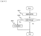
- FIG. 8 is a flowchart relating to the end control of the output control unit 110 according to time.
- Example 3 is an example in which the end determination (S207) (S208) part of FIG. 2 shown in Example 1 is changed from (S801) to (S803) shown in FIG.
- the output control unit 110 updates the braking time of AC braking when AC braking is started (S801).
- the output control unit 110 compares the braking stop time stored in the storage unit 112 in advance with the updated braking time (S802). If the braking stop time is within the braking stop time, the braking is continued. The AC braking is terminated (S803).
- the power converter may be restarted or stopped after the AC braking is finished. Setting the braking stop time is effective when braking is required even after the AC motor is stopped.
- FIG. 9 is an example of a diagram showing the relationship between the state of braking and time.
- an alternating current flowing in the U phase of the synchronous motor and an effective current are shown as an example of the braking current.
- FIG. 9 shows a state where the output is interrupted after a certain time has elapsed since the start of AC braking as described in FIG.
- a braking time for completely stopping by the AC braking is set in advance.
- the power conversion device provides a mechanism that can apply a braking force only in the direction to stop until the stop, monitor the time, and stop by the above-described method even when the inertia load is large.
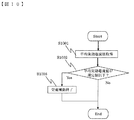
- FIG. 10 is a flowchart regarding the end determination based on the average current of the output control unit 110.
- Example 3 is an example in which the end determination (S207) (S208) part of FIG. 2 shown in Example 1 is changed from (S1001) to (S1003) shown in FIG.
- the output control unit 110 acquires an average effective current value when AC braking is started (S1001).
- the output control unit 110 compares the specified value of the stop determination current stored in the storage unit 112 in advance with the acquired average effective current value (S1002). If this happens, the AC braking is terminated (S803).
- the power converter may be restarted or stopped after the AC braking is finished. Setting the stop determination current can be determined to be a stop using the average effective current value that flows due to rotation, so that it is possible to prevent the AC voltage from being applied unnecessarily for a long time and to reduce deterioration of the constituent elements of the AC conversion unit 104. be able to.
- FIG. 11 is an example of a diagram showing the relationship between the state of braking and time.
- the current flowing in the U phase of the synchronous motor and the average effective current value are shown as an example of the braking current.
- FIG. 11 shows a state in which the output is shut off after the average effective current value falls below the end determination threshold after the AC braking is started as described in FIG.
- the AC braking end determination threshold value is set in advance to a current value at which the synchronous motor can be regarded as stopped.
- the power conversion device provides a mechanism that can apply the braking force only in the direction to stop until the stop and monitor and stop the output current even when the inertial load is large by the method as described above. .
- the present embodiment discloses an embodiment of the power conversion device described below and a control method for these power conversion devices.
- An AC converter that includes an AC converter that converts DC power into desired AC power, a current detector that detects a current flowing through the AC converter, and a controller that controls the output of the AC converter. Then, the control unit performs AC braking in which braking is performed by flowing an AC current under a condition that does not apply rotational force to the AC motor while the AC motor connected to the power converter is in a deceleration mode. It is the power converter device characterized by the above.
- the AC braking performed by the control unit is performed by applying an AC voltage having a frequency higher than the rotational frequency of the AC motor.
- the application of the AC voltage in the control unit is performed by fixing the phase in an arbitrary axial direction and applying the AC voltage in one axial direction.
- the control unit controls the AC voltage based on a comparison between an output current value obtained by converting the current detected by the current detector and a predetermined value. Device.
- control unit is a power conversion device that controls an AC voltage based on a predetermined voltage value determined due to an element of the AC conversion unit.
- control unit is a power conversion device that performs short-circuit braking in which three phases are short-circuited to perform braking, and performs AC braking when a predetermined speed or less is reached.
- control unit is a power conversion device that performs the AC braking for a predetermined time set in advance and ends the braking.
- control unit is a power conversion device that ends a braking operation based on a predetermined AC average current value.
- this invention is not limited to an above-described Example, Various modifications are included.
- the above-described embodiments have been described in detail for easy understanding of the present invention, and are not necessarily limited to those having all the configurations described.
- a part of the configuration of one embodiment can be replaced with the configuration of another embodiment, and the configuration of another embodiment can be added to the configuration of one embodiment.
- Each of the above-described configurations, functions, processing units, processing means, and the like may be realized by hardware by designing a part or all of them with, for example, an integrated circuit.
- Each of the above-described configurations, functions, and the like may be realized by software by interpreting and executing a program that realizes each function by the processor.
- Information such as programs, tables, and files for realizing each function can be stored in a recording device such as a memory, a hard disk, an SSD (Solid State Drive), or a recording medium such as an IC card, an SD card, or a DVD.
- the control lines and information lines indicate what is considered necessary for the explanation, and not all the control lines and information lines on the product are necessarily shown. Actually, it may be considered that almost all the components are connected to each other.
Landscapes
- Engineering & Computer Science (AREA)
- Power Engineering (AREA)
- Stopping Of Electric Motors (AREA)
- Control Of Ac Motors In General (AREA)
Abstract
Priority Applications (4)
| Application Number | Priority Date | Filing Date | Title |
|---|---|---|---|
| CN201480081055.8A CN107078679B (zh) | 2014-11-07 | 2014-11-07 | 电力转换装置和电力转换装置的控制方法 |
| PCT/JP2014/079519 WO2016072003A1 (fr) | 2014-11-07 | 2014-11-07 | Convertisseur de puissance et procédé de commande de convertisseur de puissance |
| JP2016557412A JP6353925B2 (ja) | 2014-11-07 | 2014-11-07 | 電力変換装置および電力変換装置の制御方法 |
| EP14905548.5A EP3229367B1 (fr) | 2014-11-07 | 2014-11-07 | Convertisseur de puissance et procédé de commande de convertisseur de puissance |
Applications Claiming Priority (1)
| Application Number | Priority Date | Filing Date | Title |
|---|---|---|---|
| PCT/JP2014/079519 WO2016072003A1 (fr) | 2014-11-07 | 2014-11-07 | Convertisseur de puissance et procédé de commande de convertisseur de puissance |
Publications (1)
| Publication Number | Publication Date |
|---|---|
| WO2016072003A1 true WO2016072003A1 (fr) | 2016-05-12 |
Family
ID=55908755
Family Applications (1)
| Application Number | Title | Priority Date | Filing Date |
|---|---|---|---|
| PCT/JP2014/079519 Ceased WO2016072003A1 (fr) | 2014-11-07 | 2014-11-07 | Convertisseur de puissance et procédé de commande de convertisseur de puissance |
Country Status (4)
| Country | Link |
|---|---|
| EP (1) | EP3229367B1 (fr) |
| JP (1) | JP6353925B2 (fr) |
| CN (1) | CN107078679B (fr) |
| WO (1) | WO2016072003A1 (fr) |
Cited By (2)
| Publication number | Priority date | Publication date | Assignee | Title |
|---|---|---|---|---|
| CN107317527A (zh) * | 2017-08-11 | 2017-11-03 | 常州机电职业技术学院 | 无刷直流电机、无刷直流电机制动控制方法及装置 |
| GB2565059A (en) * | 2017-07-28 | 2019-02-06 | Edwards Ltd | Induction motor control |
Families Citing this family (1)
| Publication number | Priority date | Publication date | Assignee | Title |
|---|---|---|---|---|
| JPH0642809Y2 (ja) | 1990-04-17 | 1994-11-09 | 石原機械工業株式会社 | コアドリル |
Citations (3)
| Publication number | Priority date | Publication date | Assignee | Title |
|---|---|---|---|---|
| JPS62261398A (ja) * | 1986-05-09 | 1987-11-13 | 株式会社東芝 | 脱水用モ−タの制動装置 |
| JP2008220100A (ja) * | 2007-03-06 | 2008-09-18 | Jtekt Corp | モータ制御装置 |
| JP2013188000A (ja) * | 2012-03-07 | 2013-09-19 | Tsubaki Emerson Co | モータ駆動装置 |
Family Cites Families (5)
| Publication number | Priority date | Publication date | Assignee | Title |
|---|---|---|---|---|
| JPS59117477A (ja) * | 1982-12-24 | 1984-07-06 | Toshiba Corp | 電動機の制御装置 |
| US6262555B1 (en) * | 1998-10-02 | 2001-07-17 | Robicon Corporation | Apparatus and method to generate braking torque in an AC drive |
| US6831432B2 (en) * | 2001-12-05 | 2004-12-14 | Matsushita Electric Industrial Co., Ltd. | Motor driving device and motor driving method |
| JP5372705B2 (ja) * | 2009-11-04 | 2013-12-18 | 株式会社日立産機システム | 電力変換装置 |
| WO2012011184A1 (fr) * | 2010-07-22 | 2012-01-26 | トヨタ自動車株式会社 | Système de commande de véhicule |
-
2014
- 2014-11-07 EP EP14905548.5A patent/EP3229367B1/fr active Active
- 2014-11-07 CN CN201480081055.8A patent/CN107078679B/zh active Active
- 2014-11-07 JP JP2016557412A patent/JP6353925B2/ja active Active
- 2014-11-07 WO PCT/JP2014/079519 patent/WO2016072003A1/fr not_active Ceased
Patent Citations (3)
| Publication number | Priority date | Publication date | Assignee | Title |
|---|---|---|---|---|
| JPS62261398A (ja) * | 1986-05-09 | 1987-11-13 | 株式会社東芝 | 脱水用モ−タの制動装置 |
| JP2008220100A (ja) * | 2007-03-06 | 2008-09-18 | Jtekt Corp | モータ制御装置 |
| JP2013188000A (ja) * | 2012-03-07 | 2013-09-19 | Tsubaki Emerson Co | モータ駆動装置 |
Non-Patent Citations (1)
| Title |
|---|
| See also references of EP3229367A4 * |
Cited By (3)
| Publication number | Priority date | Publication date | Assignee | Title |
|---|---|---|---|---|
| GB2565059A (en) * | 2017-07-28 | 2019-02-06 | Edwards Ltd | Induction motor control |
| CN107317527A (zh) * | 2017-08-11 | 2017-11-03 | 常州机电职业技术学院 | 无刷直流电机、无刷直流电机制动控制方法及装置 |
| CN107317527B (zh) * | 2017-08-11 | 2019-05-03 | 常州机电职业技术学院 | 无刷直流电机、无刷直流电机制动控制方法及装置 |
Also Published As
| Publication number | Publication date |
|---|---|
| JP6353925B2 (ja) | 2018-07-04 |
| EP3229367A1 (fr) | 2017-10-11 |
| EP3229367A4 (fr) | 2018-07-11 |
| CN107078679B (zh) | 2020-03-31 |
| EP3229367B1 (fr) | 2020-10-07 |
| CN107078679A (zh) | 2017-08-18 |
| JPWO2016072003A1 (ja) | 2017-06-29 |
Similar Documents
| Publication | Publication Date | Title |
|---|---|---|
| JP5866034B2 (ja) | 電動機駆動装置 | |
| JP6277288B2 (ja) | 監視装置と監視方法およびそれらを備える制御装置と制御方法 | |
| JP5954313B2 (ja) | モータ制御システム、制御装置及び制御方法 | |
| JP6241453B2 (ja) | モータ駆動装置 | |
| JP6203784B2 (ja) | 同期電動機の制御装置 | |
| JP6353925B2 (ja) | 電力変換装置および電力変換装置の制御方法 | |
| WO2015045529A1 (fr) | Dispositif de conversion d'énergie et procédé de conversion d'énergie | |
| JP6967470B2 (ja) | 制御装置 | |
| JP6286450B2 (ja) | 電力変換装置 | |
| JP5476788B2 (ja) | インバータ装置 | |
| JP6282338B2 (ja) | 電力変換装置及び電力変換方法 | |
| JP5516087B2 (ja) | 誘導電動機の制御方法 | |
| CN103166560A (zh) | 电动机的控制装置 | |
| JP6471352B2 (ja) | 洗濯機のモータ制御装置 | |
| JP6357648B2 (ja) | 直流電動機駆動装置とそれを搭載した天井埋込型換気装置 | |
| CN111987974B (zh) | 旋转电机控制装置 | |
| JP5631200B2 (ja) | 同期電動機の制御装置、及び同期発電機の制御装置 | |
| JP5659330B2 (ja) | 電力変換装置 | |
| JP6357649B2 (ja) | 直流電動機駆動装置とそれを搭載した天井埋込型換気装置 | |
| JP2013135516A (ja) | 電力変換装置及び空気調和機 | |
| JP5997953B2 (ja) | モータの駆動制御装置 | |
| WO2018164000A1 (fr) | Dispositif d'entraînement de moteur | |
| JP2009148065A (ja) | 電動機制御装置及びこれを搭載した空気調和機 | |
| WO2024247146A1 (fr) | Dispositif de commande de moteur, dispositif de direction assistée électrique, et véhicule | |
| KR101620853B1 (ko) | 유도전동기 구동 제어 장치 |
Legal Events
| Date | Code | Title | Description |
|---|---|---|---|
| 121 | Ep: the epo has been informed by wipo that ep was designated in this application |
Ref document number: 14905548 Country of ref document: EP Kind code of ref document: A1 |
|
| REEP | Request for entry into the european phase |
Ref document number: 2014905548 Country of ref document: EP |
|
| WWE | Wipo information: entry into national phase |
Ref document number: 2014905548 Country of ref document: EP |
|
| ENP | Entry into the national phase |
Ref document number: 2016557412 Country of ref document: JP Kind code of ref document: A |
|
| NENP | Non-entry into the national phase |
Ref country code: DE |