WO2016072004A1 - Appareil d'enregistrement/de reproduction d'hologramme - Google Patents
Appareil d'enregistrement/de reproduction d'hologramme Download PDFInfo
- Publication number
- WO2016072004A1 WO2016072004A1 PCT/JP2014/079520 JP2014079520W WO2016072004A1 WO 2016072004 A1 WO2016072004 A1 WO 2016072004A1 JP 2014079520 W JP2014079520 W JP 2014079520W WO 2016072004 A1 WO2016072004 A1 WO 2016072004A1
- Authority
- WO
- WIPO (PCT)
- Prior art keywords
- hologram recording
- recording medium
- opening
- reproducing apparatus
- signal
- Prior art date
- Legal status (The legal status is an assumption and is not a legal conclusion. Google has not performed a legal analysis and makes no representation as to the accuracy of the status listed.)
- Ceased
Links
Images


Classifications
-
- G—PHYSICS
- G03—PHOTOGRAPHY; CINEMATOGRAPHY; ANALOGOUS TECHNIQUES USING WAVES OTHER THAN OPTICAL WAVES; ELECTROGRAPHY; HOLOGRAPHY
- G03H—HOLOGRAPHIC PROCESSES OR APPARATUS
- G03H1/00—Holographic processes or apparatus using light, infrared or ultraviolet waves for obtaining holograms or for obtaining an image from them; Details peculiar thereto
- G03H1/04—Processes or apparatus for producing holograms
-
- G—PHYSICS
- G03—PHOTOGRAPHY; CINEMATOGRAPHY; ANALOGOUS TECHNIQUES USING WAVES OTHER THAN OPTICAL WAVES; ELECTROGRAPHY; HOLOGRAPHY
- G03H—HOLOGRAPHIC PROCESSES OR APPARATUS
- G03H1/00—Holographic processes or apparatus using light, infrared or ultraviolet waves for obtaining holograms or for obtaining an image from them; Details peculiar thereto
- G03H1/22—Processes or apparatus for obtaining an optical image from holograms
-
- G—PHYSICS
- G11—INFORMATION STORAGE
- G11B—INFORMATION STORAGE BASED ON RELATIVE MOVEMENT BETWEEN RECORD CARRIER AND TRANSDUCER
- G11B7/00—Recording or reproducing by optical means, e.g. recording using a thermal beam of optical radiation by modifying optical properties or the physical structure, reproducing using an optical beam at lower power by sensing optical properties; Record carriers therefor
- G11B7/004—Recording, reproducing or erasing methods; Read, write or erase circuits therefor
- G11B7/0065—Recording, reproducing or erasing by using optical interference patterns, e.g. holograms
-
- G—PHYSICS
- G11—INFORMATION STORAGE
- G11B—INFORMATION STORAGE BASED ON RELATIVE MOVEMENT BETWEEN RECORD CARRIER AND TRANSDUCER
- G11B7/00—Recording or reproducing by optical means, e.g. recording using a thermal beam of optical radiation by modifying optical properties or the physical structure, reproducing using an optical beam at lower power by sensing optical properties; Record carriers therefor
- G11B7/12—Heads, e.g. forming of the optical beam spot or modulation of the optical beam
- G11B7/135—Means for guiding the beam from the source to the record carrier or from the record carrier to the detector
Definitions
- the present invention relates to an apparatus for performing recording or reproduction using holography.
- Hologram recording technology is a method in which signal light having page data information two-dimensionally modulated by a spatial light modulator is superimposed on reference light inside the recording medium, and the interference fringe pattern generated at that time is placed in the recording medium. This is a technique for recording information on a recording medium by causing refractive index modulation.
- Japanese Patent Laid-Open No. 2004-151867 states, “As a problem for the practical application of a hologram recording apparatus, when the apparatus vibrates during the exposure time, the optical paths of the reference light and the signal light change, or the optical paths of the signal light and the reference light fluctuate. In some cases, the interference fringes change and recording cannot be performed properly.
- Patent Document 2 discloses a configuration in which a disturbance observer is applied to an optical disc apparatus with respect to a problem of vibration or impact applied from the outside.
- hologram recording technology One major advantage of hologram recording technology is that it can record large amounts of data. However, when an increase in recording capacity is pursued, it is necessary to improve the accuracy and robustness of positioning control regarding the position where the signal light and the reference light are irradiated, as compared with the conventional case.
- an object of the present invention is to provide a hologram recording / reproducing apparatus that realizes suitable recording and / or reproduction with respect to a hologram recording medium even when vibration or impact is applied from the outside.
- the above problem is solved by, for example, the invention described in the scope of claims.
- the present application includes a plurality of means for solving the above-mentioned problems.
- a hologram is formed on a hologram recording medium by interference between signal light and reference light, and information is recorded.
- a hologram recording / reproducing apparatus for reproducing information by irradiating a hologram formed on a recording medium with reference light, an optical system for irradiating the hologram recording medium with the signal light and / or the reference light, and An opening through which either or both of signal light and diffracted light generated when the hologram is irradiated with the reference light, an opening position control unit that controls the position of the opening, and the hologram recording medium include the opening An irradiation position changing unit that changes an irradiation position irradiated with the signal light or the reference light; an irradiation position control unit that controls the irradiation position changing unit; and the holo A detection unit that detects information on the position of either the ram recording medium or the optical system, and the opening position control unit controls the position of the opening based on an output signal of the detection unit. To do.
- a hologram recording / reproducing apparatus that realizes suitable recording and / or reproduction with respect to a hologram recording medium even when external vibration or impact is applied.
- FIG. 1 is a block diagram showing a hologram recording / reproducing apparatus of Example 1.
- FIG. FIG. 3 is a diagram for explaining a recording principle of the hologram recording / reproducing apparatus of Example 1. It is a figure explaining the reproduction
- FIG. FIG. 3 is a block diagram illustrating an opening position control circuit according to the first embodiment. It is a figure explaining SES in Example 1.
- FIG. It is a figure explaining the X-axis displacement of the opening part in Example 1.
- FIG. FIG. 3 is a block diagram illustrating a spindle error signal generation circuit and a spindle control circuit according to the first embodiment.
- FIG. 3 is a block diagram illustrating a radius error signal generation circuit and a radial direction conveyance control circuit according to the first embodiment.
- FIG. 3 is a block diagram illustrating a focus error signal generation circuit and a focus control circuit according to the first exemplary embodiment. It is a flowchart until the preparation of recording or reproduction
- FIG. 6 is a block diagram showing a hologram recording / reproducing apparatus of Example 3.
- FIG. 10 is a block diagram illustrating an opening position control circuit according to a third embodiment. 6 is a block diagram showing a hologram recording / reproducing apparatus in Example 4.
- FIG. 10 is a block diagram illustrating an opening position control circuit according to a fourth embodiment.
- FIG. 10 is a block diagram showing a hologram recording / reproducing apparatus in Example 5.
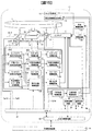
- FIG. 1 is a block diagram showing a recording / reproducing apparatus for a holographic recording medium that records and / or reproduces digital information using holography.
- the hologram recording / reproducing device 10 is connected to an external control device 91 via an input / output control circuit 90.
- the hologram recording / reproducing apparatus 10 receives an information signal to be recorded from the external control device 91 by the input / output control circuit 90.
- the hologram recording / reproducing device 10 transmits the reproduced information signal to the external control device 91 by the input / output control circuit 90.
- the hologram recording medium 1 in this embodiment has a disk shape and has an angle detection mark for detecting the rotation angle of the hologram recording medium 1.
- the hologram recording / reproducing apparatus 10 includes a pickup 11, a reproduction reference light optical system 12, a cure optical system 13, a rotation angle detection sensor 14, a radial position detection sensor 15, a focus detection sensor 17, a spindle motor 50, and a radial direction conveyance unit 51. , A Z stage 52 is provided.
- the spindle motor 50 has a medium attaching / detaching portion (not shown) that allows the hologram recording medium 1 to be attached to and detached from the rotation axis.
- the hologram recording medium 1 is configured to be rotatable by the spindle motor 50.
- the hologram recording medium 1 is configured to be movable in the radial direction by the radial transport unit 51 with reference to the position of the pickup 11.
- the hologram recording medium 1 is configured to be movable by a Z stage 52 in a direction parallel to the rotation axis (hereinafter referred to as a focus direction) with reference to the position of the pickup 11.
- the pickup 11 is used when information is recorded on the hologram recording medium 1 and when information recorded on the hologram recording medium 1 is reproduced.
- the hologram recording medium 1 is irradiated with reference light and signal light, and digital information is recorded on the recording medium using holography.
- the information signal to be recorded is sent to the spatial light modulator 212 (described later) in the pickup 11 by the controller 80 via the signal generation circuit 81, and the signal light is modulated by the spatial light modulator 212.
- the reproduction reference light optical system 12 When reproducing the information recorded on the hologram recording medium 1, the reproduction reference light optical system 12 generates a light wave that causes the reference light emitted from the pickup 11 to enter the hologram recording medium 1 in the direction opposite to that during recording. To do. Diffracted light reproduced by the reproduction reference light is detected by a photodetector 226 described later in the pickup 11, and a signal is reproduced by a signal processing circuit 82.
- Adjustment of the irradiation time of the reference light and the signal light with which the hologram recording medium 1 is irradiated is performed by the controller 80 transmitting a signal to the shutter control circuit 84, and the shutter control circuit 84 using the signal transmitted from the controller 80. Control is performed to open and close.
- the cure optical system 13 plays a role of generating a light beam used for pre-cure and post-cure of the hologram recording medium 1.
- Pre-curing is a pre-process for irradiating a predetermined light beam in advance before irradiating the reference light and signal light to the desired position when recording information at the desired position in the hologram recording medium 1.
- Post-cure is a post-process for irradiating a predetermined light beam after recording information at a desired position in the hologram recording medium 1 so that additional recording cannot be performed at the desired position.
- the light beam used for pre-cure and post-cure is preferably incoherent light, that is, light with low coherence.
- the light source drive circuit 83 supplies a predetermined light source drive current to the light sources in the pickup 11 and the cure optical system 13 in accordance with an instruction from the controller 80.
- the light source of the light source in the pickup 11 and the cure optical system 13 emits a light beam with a predetermined light amount.
- the pickup 11, the reproduction reference light optical system 12, the cure optical system 13, and the angle error detection optical system 30 may be simplified by combining some optical system configurations or all optical system configurations. .
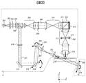
- FIG. 2 shows a recording principle in an example of a basic optical system configuration of the pickup 11 and the reproducing reference light optical system 12 in the hologram recording / reproducing apparatus 10.
- the reproduction reference light optical system 12 includes an actuator 224 and a galvanometer mirror 225.
- the light beam emitted from the light source 201 passes through the collimator lens 202 and enters the shutter 203.
- the optical element 204 composed of, for example, a half-wave plate or the like, adjusts the light quantity ratio of p-polarized light and s-polarized light to a desired ratio.
- the light beam enters a PBS (Polarization Beam Splitter) prism 205.
- the light beam that has passed through the PBS prism 205 functions as signal light 206, and after the light beam diameter is expanded by the beam expander 208, the light beam passes through the phase mask 209, the relay lens 210, and the PBS prism 211 and passes through the spatial light modulator 212. Is incident on.
- the signal light 206 to which information is added by the spatial light modulator 212 is reflected by the PBS prism 211 and propagates through the opening 214 whose position can be adjusted by the relay lens 213 and the actuator 230.
- the opening 214 functions as a spatial filter. Thereafter, the signal light is condensed on the hologram recording medium 1 by the objective lens 215.
- the coordinate axes (x, y, z) are taken as shown in FIG.
- the y-axis is a direction perpendicular to the paper surface and is a direction perpendicular to the incident surface of the reference light.
- the x-axis is a direction parallel to the hologram recording medium 1 in the drawing, and the z-axis is a direction perpendicular to the hologram recording medium 1.
- These axes can be rephrased as follows.
- the x-axis is the moving direction of the hologram recording medium 1 when the spindle motor 50 is driven
- the y-axis is the moving direction of the hologram recording medium 1 when the radial transport unit 51 is driven
- the z-axis is driving the Z stage 52. This is the moving direction of the hologram recording medium 1 at the time.
- the actuator 230 in this embodiment can individually control each of the x axis, the y axis, and the z axis. That is, the position of the opening 214 functioning as a spatial filter can be controlled with three degrees of translation. This control is referred to as opening position control.
- the light beam reflected from the PBS prism 205 acts as reference light 207, which is set by the polarization direction conversion element 216 to a predetermined polarization direction according to recording or reproduction, and then passes through the mirror 217 and the galvanometer mirror 218.
- the galvanometer mirror 220 can adjust the angle in the paper surface by the actuator 221, and the incident angle of the reference light incident on the hologram recording medium 1 after passing through the lens 222 and the lens 223 can be set to a desired angle.
- an element that converts the wavefront of the reference light may be used instead of the galvanometer mirror.
- the galvanometer mirror 218 can adjust the angle in the direction perpendicular to the paper surface by the actuator 219, and the incident angle in the direction perpendicular to the paper surface of the reference light incident on the hologram recording medium 1 after passing through the lens 222 and the lens 223 is set to a desired angle. Can be set.
- the signal light 206 and the reference light 207 are incident on the hologram recording medium 1 so as to overlap each other, whereby an interference fringe pattern is formed in the hologram recording medium 1, and this pattern is written to the hologram recording medium 1. Record information with.
- the incident angle of the reference light incident on the hologram recording medium 1 can be changed by the galvanometer mirror 220, recording by angle multiplexing is possible.
- holograms corresponding to each incident angle are called pages, and a set of pages angle-multiplexed in the same area is called a book. To do.
- FIG. 3 shows a reproduction principle in an example of a basic optical system configuration of the pickup 11 and the reproduction reference light optical system 12 in the hologram recording / reproduction apparatus 10.
- the reference beam 207 is incident on the hologram recording medium 1 as described above, and the light beam transmitted through the hologram recording medium 1 is reflected by the galvanometer mirror 225 whose angle can be adjusted by the actuator 224.
- the reproduction reference light is generated.
- the diffracted light reproduced by the reproduction reference light propagates through the objective lens 215, the relay lens 213, and the opening 214. Thereafter, the diffracted light passes through the PBS prism 211 and enters the photodetector 226, and the recorded signal can be reproduced.
- an image sensor such as a CMOS image sensor or a CCD image sensor can be used as the photodetector 226.
- any element may be used as long as page data can be reproduced.
- the opening 214 has a photodetector (not shown). By providing this photodetector, it is possible to detect whether the diffracted light regenerated by the regenerative reference light is appropriately passing through the opening 214. That is, by using the signal of the photodetector provided in the opening 214, it is possible to detect the positional deviation of the opening 214 during reproduction.
- the position where signal light and / or reference light is irradiated (hereinafter referred to as the irradiation position) is determined by the position of the pickup 11 and is a position fixed to the apparatus.
- the spindle motor 50, the radial conveyance unit 51, and the Z stage 52 function as means for changing the position on the hologram recording medium 1 to which the signal light and / or reference light is irradiated.
- the rotation angle detection sensor 14 detects the rotation angle of the hologram recording medium 1 using an angle detection mark (not shown) provided on the hologram recording medium 1.
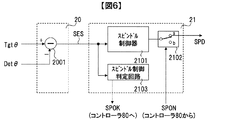
- the spindle error signal generation circuit 20 outputs the difference between the rotation angle target value Tgt ⁇ output from the controller 80 and the value det ⁇ detected by the rotation angle detection sensor 14 as a spindle error signal SES.
- the spindle control circuit 21 When changing the rotation angle irradiated with the signal light and / or the reference light, the spindle control circuit 21 generates a drive signal based on the SES and drives the spindle motor 50 via the spindle drive circuit 22. Thereby, the hologram recording medium 1 rotates, and the rotation angle at which the signal light and / or the reference light is irradiated can be controlled. This control is called spindle control.
- a scale 16 having a predetermined pattern is fixed to the movable part of the radial direction transport part 51.
- the radial position detection sensor 15 detects the position of the movable part of the radial direction transport part 51 using the scale 16.
- the radius error signal generation circuit 23 outputs the difference between the radius target value TgtR output from the controller 80 and the value detR detected by the radius position detection sensor 15 as a radius error signal RES.
- the radial transport control circuit 24 When changing the radial position irradiated with the signal light and / or the reference light, the radial transport control circuit 24 generates a drive signal based on the RES, and the radial transport unit 51 via the radial transport drive circuit 25. Drive.
- the hologram recording medium 1 is conveyed in the radial direction, and the radial position irradiated with the signal light and / or the reference light can be controlled. This control is called radial position control.
- the focus detection sensor 17 irradiates light on the surface of the hologram recording medium 1 and detects the reflected light to measure the distance to the hologram recording medium 1, that is, the focus position.
- the focus error signal generation circuit 26 outputs the difference between the predetermined value and the value detZ detected by the focus detection sensor 17 as the focus error signal FES.
- the focus control circuit 27 generates a drive signal based on the FES, and drives the Z stage 52 via the focus drive circuit 28. Thereby, the hologram recording medium 1 is conveyed in the focus direction, and the focus position where the signal light and / or the reference light is irradiated can be controlled. This control is referred to as focus control.
- the spindle control circuit 21, the radial direction conveyance control circuit 24, and the focus control circuit 27 return information to the controller 80 as to whether or not each drive has been completed.
- SES, RES, and FES are also input to the opening position control circuit 30.
- the opening position control circuit 30 generates a drive signal based on a command signal from the controller 80 and drives the actuator 230 in the pickup 11 via the opening position drive circuit 31. Thereby, the position of the opening 214 is controlled.
- the incident angle control circuit 70 controls the angles of the actuator 221 in the pickup 11 and the actuator 224 in the reproduction reference light optical system 12 via the incident angle drive circuit 71.
- the incident angle control circuit 70 receives a target angle Tgt ⁇ from the controller 80, an output signal of an angle detection sensor (not shown) provided in the actuator 221, and an output signal of an angle detection sensor (not shown) provided in the actuator 224. As input. If the output signal of the angle detection sensor provided in the actuator 221 is used, the incident angle at which the reference light reflected by the galvano mirror 220 is incident on the hologram recording medium 1 can be calculated, so that the incident angle becomes Tgt ⁇ . It can be controlled. The same applies to the actuator 224.
- the incident angle of the reference light incident on the hologram recording medium 1 is controlled.
- an optical encoder can be used as the angle detection sensor provided in the actuator 221, the actuator 224, and the actuator 219.
- the recording technique using the principle of angle multiplexing of holography tends to have a very small tolerance for deviation of the incident angle of the reference beam. Therefore, a mechanism for detecting the shift amount of the incident angle of the reference light is provided in the pickup 11 without using the angle detection sensor provided in the actuator 221, and the incident angle control circuit 70 inputs the output signal of the mechanism. As a configuration, a signal for use in controlling the incident angle of the reference light may be generated.
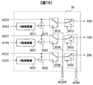
- the opening position control circuit 30 includes a displacement conversion gain 3010, an X axis compensator 3011, an X axis control switch 3012, a Y axis compensator 3021, a Y axis control switch 3022, a Z axis compensator 3031, and a Z axis control switch 3032.
- the displacement conversion gain 3010 receives SES, multiplies the gain k designated by the controller 80, and outputs a signal converted into displacement on the hologram recording medium 1. Since SES is a signal indicating the difference between the current rotation angle and the target rotation angle, when the hologram recording medium 1 rotates by a predetermined amount, the signal light emitted from the objective lens 215 and the amount of change in voltage of SES and The conversion coefficient k when converting to the displacement (unit: ⁇ m) of the irradiation position of the reference light is inversely proportional to the radius R. This is clear from the fact that even when the rotation angle is the same, the drawn arc becomes longer as the radius increases.
- the controller 80 designates the gain k of the displacement conversion gain 3010 from the information on the radius R.
- the X-axis compensator 3011 performs gain and phase compensation on the output signal of the displacement conversion gain 3010, and outputs a drive signal for controlling the position of the opening 214 in the X-axis direction.
- the X-axis compensator 3011 can be configured as a digital filter including an integrator, for example.
- the X-axis control switch 3012 switches whether to output the output signal of the X-axis compensator 3011 according to the control signal APON from the controller 80, and outputs it as an XDS signal.
- XDS is supplied to the actuator 230 via the opening position drive circuit 31, and the position of the opening 214 in the X-axis direction is controlled.
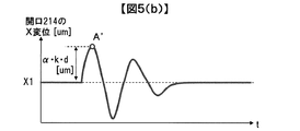
- the SES is input to the X-axis compensator 3011 as a target trajectory. Therefore, by appropriately designing the gains of the variable gain 3010 and the X-axis compensator 3011, the X-axis displacement of the opening 214 can be controlled by ⁇ times the displacement indicated by the SES.
- FIG. 5A shows SES
- FIG. 5B shows the X-axis displacement of the opening 214.
- SES is an electrical signal
- the unit is volts.
- d [V] be the difference between the voltage at point A and the value before application of external vibration.
- the amount of vibration at point A due to external vibration is k ⁇ d [ ⁇ m]. That is, the displacement indicated by the displacement of the SES of d [V] is k ⁇ d [ ⁇ m].
- the waveform can be approximately equal to the waveform.
- X1 be the X-axis displacement of the opening 214 before application of external vibration.
- a ′ a point corresponding to the point A in SES.
- the gain of the X-axis compensator 3011 is designed so that the difference between the displacement at the point A ′ and the displacement before application of external vibration is ⁇ ⁇ (k ⁇ d) [ ⁇ m].
- the opening 214 moves in the X-axis direction by a displacement that is ⁇ times the displacement amount.
- the description of whether the SES polarity matches the X axis is omitted.
- the polarity of SES is opposite to that of the X axis, and actually, the opening 214 is displaced in the opposite direction to the direction of displacement of the hologram recording medium 1 indicated by the displacement of SES. The reason for this will be described later.
- the Y-axis compensator 3021 performs gain and phase compensation for the RES, and outputs a drive signal for controlling the position of the opening 214 in the Y-axis direction.
- the Y-axis compensator 3021 can be configured as a digital filter including an integrator, for example.
- the gain of the Y-axis compensator 3021 is designed so that the opening 214 moves in the Y-axis direction by a displacement ⁇ times the displacement amount.
- the Z-axis compensator 3031 performs gain and phase compensation on the EES, and outputs a drive signal for controlling the position of the opening 214 in the Z-axis direction.
- the Z-axis compensator 3031 can be configured as a digital filter including an integrator, for example.
- the Z-axis compensator when the hologram recording medium 1 is displaced in the Z-axis direction by external vibration, the Z-axis compensator so that the opening 214 moves in the Z-axis direction by a displacement ⁇ times the displacement amount.
- a gain of 3031 is designed.
- the Y-axis control switch 3022 switches whether to output the output signal of the Y-axis compensator 3021 according to the control signal APON from the controller 80, and outputs it as a YDS signal.
- the Z-axis control switch 3032 switches whether to output the output signal of the Z-axis compensator 3031 according to the control signal APON from the controller 80 and outputs it as a ZDS signal.
- YDS and ZDS are supplied to the actuator 230 via the opening position drive circuit 31, and the positions of the opening 214 in the Y-axis and Z-axis directions are controlled.
- the X-axis control switch 3012, the Y-axis control switch 3022, and the Z-axis control switch 3032 output the output signal of the compensator for each axis when the APON signal is High, and turn off the output when the APON signal is Low. .
- the spindle error signal generation circuit 20 includes a subtractor 2001.
- the subtracter 2001 subtracts Tgt ⁇ and Det ⁇ , and outputs the value of (Tgt ⁇ Det ⁇ ) as SES.
- the spindle control circuit 21 includes a spindle controller 2101, a spindle output control switch 2102, and a spindle control determination circuit 2103.
- the spindle controller 2101 performs gain and phase compensation for the SES, and outputs a drive signal for controlling the rotation angle of the spindle motor 50.
- the subtractor 2001 and the spindle controller 2101 constitute a feedback control system for controlling the rotation angle of the spindle motor 50. Further, the target value of the feedback control system is Tgt ⁇ , and control is performed so that the rotation angle of the spindle motor 50 becomes Tgt ⁇ .
- the spindle output control switch 2102 switches whether to output the output signal of the spindle controller 2101 according to the control signal SPON from the controller 80, and outputs it as an SPD signal.
- the spindle output control switch 2102 outputs the output signal of the spindle controller 2101 when the SPON signal is High, and turns off the output when the SPON signal is Low.
- the spindle control determination circuit 2103 receives the SES, determines whether or not the rotation angle of the hologram recording medium 1 is near the angle command value Tgt ⁇ , and outputs it as a SPOK signal. When the rotation angle of the hologram recording medium 1 is a value in the vicinity of the angle command value Tgt ⁇ , the SPOK signal is assumed to be High.
- the spindle control determination circuit 2103 can be realized, for example, by measuring an elapsed time after the SES becomes a predetermined threshold value or less and making a determination by continuing the measurement time for a predetermined time or more.
- the SPOK signal that is the determination result is input to the controller 80. With the above configuration, the spindle control determination circuit 2103 functions as a circuit for determining convergence of spindle control.
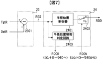
- the radius error signal generation circuit 23 includes a subtracter 2301.
- the subtracter 2301 subtracts TgtR and DetR and outputs the value of (TgtR ⁇ DetR) as RES.
- the radial direction conveyance control circuit 24 includes a radial position controller 2401, a radial position output control switch 2402, and a radial position control determination circuit 2403.
- the radial position controller 2401 performs gain and phase compensation for the RES, and outputs a drive signal for controlling the position of the movable part of the radial transport part 51.
- the subtractor 2301 and the radial position controller 2401 constitute a feedback control system for controlling the position of the movable part of the radial transport unit 51. Further, the target value of the feedback control system is TgtR, and the control is performed so that the position of the movable portion of the radial transport unit 51 is TgtR.
- the radial position output control switch 2402 switches whether to output the output signal of the radial position controller 2401 according to the control signal RDON from the controller 80, and outputs it as an RDDD signal.
- the radial position output control switch 2402 outputs the output signal of the radial position controller 2401 when the RDON signal is High, and turns off the output when the RDON signal is Low.
- the radial position control determination circuit 2403 receives RES, determines whether or not the position of the movable part of the radial direction transport part 51 is a value near the position command value TgtR, and outputs it as an RDOK signal. In addition, when the position of the movable part of the radial direction conveyance part 51 is a value in the vicinity of the position command value TgtR, the RDOK signal is assumed to be High.
- the radial position control determination circuit 2403 can be realized, for example, by measuring an elapsed time after the RES becomes a predetermined threshold value or less and making a determination by continuing the measurement time for a predetermined time or more.
- the RDOK signal that is the determination result is input to the controller 80. With the above configuration, the radial position control determination circuit 2403 functions as a circuit that determines the convergence of the radial position control.
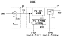
- the focus error signal generation circuit 26 includes a subtracter 2601.
- the subtractor 2601 performs subtraction between DetZ and a predetermined value Znorm, and outputs the value of (DetZ ⁇ Zorm) as FES.
- the focus control circuit 27 includes a focus controller 2701, a focus output control switch 2702, and a focus control determination circuit 2703.
- the focus controller 2701 compensates the gain and phase for the FES and outputs a drive signal for controlling the focus position of the hologram recording medium 1.
- the subtractor 2601 and the focus controller 2701 constitute a feedback control system for controlling the focus position of the hologram recording medium 1.
- the target value of the feedback control system is Znorm, and control is performed so that the distance from the focus detection sensor 17 to the hologram recording medium 1 becomes Znorm.
- the focus output control switch 2702 switches whether to output the output signal of the focus controller 2701 according to the control signal FOON from the controller 80, and outputs it as an FOD signal.
- the focus output control switch 2702 outputs the output signal of the focus controller 2701 when the FOON signal is High, and turns off the output when the FOON signal is Low.
- the focus control determination circuit 2703 receives the FES, determines whether or not the focus position of the hologram recording medium 1 is a value near Znorm, and outputs it as a FOOK signal. It is assumed that the FOOK signal becomes High when the focus position of the hologram recording medium 1 is a value near Znorm.
- the focus control determination circuit 2703 can be realized, for example, by measuring an elapsed time after the FES becomes equal to or less than a predetermined threshold and making a determination by continuing the measurement time for a predetermined time or more.
- the FOOK signal that is the determination result is input to the controller 80.
- the focus control determination circuit 2703 functions as a circuit that determines convergence of focus control.
- FIG. 9 shows a flowchart of recording and reproduction in the hologram recording / reproducing apparatus 10.
- processing relating to recording / reproduction using holography in particular will be described.
- a process from when the hologram recording medium 1 is inserted into the hologram recording / reproducing apparatus 10 until preparation for recording or reproduction is completed is referred to as a setup process.
- the process of recording information on the hologram recording medium 1 from the ready state is called a recording process
- the process of reproducing information recorded on the hologram recording medium 1 from the ready state is called a playback process.
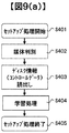
- FIG. 9A shows a flowchart of the setup process
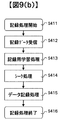
- FIG. 9B shows a flowchart of the recording process
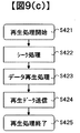
- FIG. 9C shows a flowchart of the reproduction process.
- the hologram recording / reproducing apparatus 10 determines whether, for example, the inserted medium is a medium for recording or reproducing digital information using holography. The medium is determined (step S402).
- the hologram recording / reproducing apparatus 10 reads control data provided on the hologram recording medium 1 (step S403). For example, information on the hologram recording medium 1 and information on various setting conditions at the time of recording and reproduction are obtained.
- the hologram recording / reproducing apparatus 10 After reading the control data, the hologram recording / reproducing apparatus 10 performs various adjustments according to the control data and learning processing related to the pickup 11 (step S404). Thereby, the hologram recording / reproducing apparatus 10 completes preparation for recording or reproduction, and ends the setup process (step S405).
- the hologram recording / reproducing device 10 receives the recording data from the external control device 91 (step S412), and the signal generation circuit 81 generates two-dimensional data corresponding to the data.
- the light is sent to the spatial light modulator 212 in the pickup 11.
- the holographic recording / reproducing apparatus 10 learns for various recordings such as optimization of the power of the light source 201 and optimization of the exposure time by the shutter 203 so that high quality information can be recorded on the holographic recording medium 1. Processing is performed in advance (step S413).
- the hologram recording / reproducing apparatus 10 controls the spindle motor 50 and the radial transport unit 51 using the spindle control circuit 21 and the radial transport control circuit 24.
- the hologram recording medium 1 is positioned so that the light beam irradiated from the pickup 11 and the cure optical system 13 is irradiated to a predetermined position of the hologram recording medium 1.
- the address information is reproduced, and it is confirmed whether the irradiation position of the light beam is positioned at a position corresponding to the address information.
- the spindle control circuit 21 and the radial direction conveyance control circuit 24 are used again to calculate the spindle. The operation of controlling and positioning the motor 50 and the radial conveyance unit 51 is repeated.
- the hologram recording / reproducing apparatus 10 performs a data recording process for recording data to be recorded as a hologram on the hologram recording medium 1 (step S415).
- the light irradiation angle is changed by a predetermined angle, and a hologram different from the already recorded hologram is stored to form a book.
- the recording process is terminated (step S416). Note that data recorded in the hologram storage medium 1 may be verified as necessary.
- the hologram recording / reproduction apparatus 10 first uses the spindle control circuit 21 and the radial direction conveyance control circuit 24 in the seek process (step S422), and uses the pickup 11 and the reproduction reference light optical system.
- the hologram recording medium 1 is positioned so that the light beam irradiated from 12 is irradiated to a predetermined position of the hologram recording medium 1.
- the address information is reproduced, and it is confirmed whether the irradiation position of the light beam is positioned at a position corresponding to the address information.
- the spindle control circuit 21 and the radial direction conveyance control circuit 24 are used again to calculate the spindle. The operation of controlling and positioning the motor 50 and the radial conveyance unit 51 is repeated.
- the hologram recording / reproducing apparatus 10 emits the reference beam 207 from the pickup 11 to the hologram storage medium 1.
- the diffracted light reproduced by the reference light is detected as two-dimensional data by the photodetector 226, and the signal processing circuit 82 processes the two-dimensional data to read out the data recorded on the hologram recording medium 1 (step). S423).
- the hologram recording / reproducing device 10 transmits the read data to the external control device 91 as reproduced data (step S424). When transmission of the reproduction data is completed, the reproduction process is terminated (step S425).
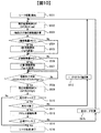
- the seek process S414 in this embodiment will be described with reference to the flowchart of FIG. Note that the same flowchart is applied to the seek process S422.
- the radius r and the rotation angle ⁇ are parameters.
- the drive shaft having the radius r is referred to as r-axis
- the drive shaft having the rotation angle ⁇ is referred to as ⁇ -axis.
- the movement of the hologram recording medium 1 in the r-axis direction and the ⁇ -axis direction is performed by the spindle motor 50 and the radial direction conveyance unit 51.
- step S501 the controller 80 sets the APON signal to low and turns off the opening position control (step S502). Subsequently, the difference between the coordinates (r, ⁇ ) of the book where the hologram of the target address is located and the current irradiation position is calculated, and the movement amount is calculated for the r axis and the ⁇ axis (step S503). Next, it is determined whether the amount of movement in the r-axis direction is other than zero (step S504). If the amount of movement in the r-axis direction is other than zero (Yes in step S504), the target radius TgtR is changed and movement in the r-axis direction is started (step S505). After step S505, the process proceeds to step S506 described later. If the amount of movement in the r-axis direction is zero (No in step S504), the process proceeds to step S506 without performing step S505.
- step S506 it is determined whether the amount of movement in the ⁇ -axis direction is other than zero. If the movement amount in the ⁇ -axis direction is other than zero (Yes in step S506), the target rotation angle Tgt ⁇ is changed and movement in the ⁇ -axis direction is started (step S507). After step S507, the process proceeds to step S508 described later. If the amount of movement in the ⁇ -axis direction is zero (No in step S506), the process proceeds to step S508 without performing step S507.
- step S508 it is determined whether or not the movement of the r-axis direction, the ⁇ -axis direction, and the focus axis has been completed.
- the focus control is always controlled. Therefore, when the position of the hologram recording medium 1 is changed in step S505 or step S507 and the focus position is changed due to the surface shake of the hologram recording medium 1, the focus position is adjusted by the focus control circuit 27.
- step S508 If it is determined that the movement has not been completed (No in step S508), the process returns to step S508 again. That is, if any one of the RDOK signal, the SPOK signal, and the FOOK signal is at a low level, it is not determined that the movement has been completed, and the operation waits until all the three signals simultaneously become a high level. It becomes.
- step S508 If it is determined that the movement has been completed (Yes in step S508), the controller 80 sets the APON signal to high to turn on the opening position control (step S509).
- step S510 it is determined whether or not the seek process during reproduction is performed. If it is not the seek process at the time of reproduction (No in step S510), the process proceeds to step S516 described later, and the seek process is terminated. In the case of seek processing at the time of reproduction (Yes in step S510), the seek processing is not finished with this, and finally, the address information obtained by reproducing the recorded hologram is used to set the target address. Continue seeking until it is correctly positioned. This is because the seek process at the time of recording is a seek process to an unrecorded portion in the hologram recording medium 1, and address information cannot be obtained.
- step S510 In the case of seek processing during playback (Yes in step S510), the first page in the book recorded at the coordinates represented by the r-axis and ⁇ -axis is played back, and the page concerned Is reproducible (step S511). If reproduction is impossible (No in step S511), it is confirmed that the hologram recording medium 1 cannot be accurately moved by the spindle motor 50 and the radial direction conveyance unit 51 from step S502 to step S509. means. Therefore, based on the predetermined retry parameter, the r-axis and ⁇ -axis retry values are calculated (step S512), and the process returns to step S502. As a result, seek processing for moving to the vicinity of the positioning is performed.
- step S511 If the hologram can be reproduced (Yes in step S511), the address information included in the reproduced hologram is acquired (step S513). Subsequently, it is determined whether or not the acquired address is a target address (step S514). If the acquired address is not the target address (No in step S514), it means that positioning has not been performed correctly. Therefore, the difference between the coordinates (r, ⁇ ) of the acquired address and the coordinates (r, ⁇ ) of the target address is calculated (step S515), and the process returns to step S502. Thereby, a seek process based on the address information of the hologram is performed.
- step S5136 If the acquired address is the target address (Yes in step S514), the seek process is terminated (step S516).
- the hologram recording medium 1 Since the hologram recording medium 1 has a large inertia, it is difficult to increase the control band for spindle control, radial position control, and focus control for controlling the position of the hologram recording medium 1. For this reason, once the hologram recording medium 1 starts to vibrate, it is difficult to converge the vibration at high speed.
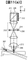
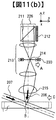
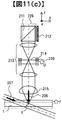
- FIG. 11 shows the light beam through which the signal light 206 passes, the reference light 207, and the hologram recording medium 1 during recording.
- the numbers in the figure are the same as those in FIG.
- FIG. 11A shows a case where the hologram recording medium 1 is at the design center position.
- the light beam exiting the spatial light modulator 212 is condensed at the position of the opening 214 due to the lens effect of the relay lens 213.
- FIG. 11B shows a case where the hologram recording medium 1 is displaced in the negative direction of the y-axis due to external vibration or the like in this embodiment, and FIG. The cases of displacement in the positive direction of the z-axis due to factors are shown.
- a light beam when the actuator 230 is displaced in the positive direction of the y-axis will be described with reference to FIG.
- the position where the signal light 206 is collected by the objective lens 215 is as shown in FIG. It moves in the negative direction of the y-axis as indicated by point B. That is, when the actuator 230 is displaced in the positive direction of the y axis, the position of the hologram formed by the interference between the signal light 206 and the reference light 207 moves in the negative direction of the y axis.
- the actuator 230 is displaced by a predetermined amount in the positive y-axis direction as shown by an arrow C in FIG.
- the influence of the displacement due to external vibration can be canceled.
- the actuator 230 is displaced by a predetermined amount in the positive direction of the z-axis as indicated by an arrow F in FIG.
- the influence of the displacement due to the external vibration can be canceled.
- the hologram recording medium 1 is irradiated with both the signal light 206 and the reference light 207 to record the hologram.
- the reference light 207 is irradiated onto the hologram recording medium 1 to generate diffracted light, thereby generating the hologram.
- reproduction In other words, by considering the propagation direction of the signal light 206 in FIG. Therefore, even when the hologram is reproduced, the influence of the displacement due to the external vibration can be canceled by displacing the actuator 230.
- the opening 214 moves in the X-axis direction by a displacement that is ⁇ times the displacement amount.
- the opening 214 moves in the Y-axis direction by a displacement that is ⁇ times the displacement
- the opening 214 moves in the Y-axis direction by a displacement ⁇ times the displacement amount.
- ⁇ , ⁇ , and ⁇ are parameters determined by the design of the optical system, and values calculated from the design information of the optical system are used.
- the X axis and the Y axis are opposite to the displacement direction of the hologram recording medium 1, and the Z axis is the same direction as the displacement direction of the hologram recording medium 1.
- FIG. 10 which is a flowchart in the present embodiment
- the position control of the actuator 230 is turned on when the seek process for the hologram recording medium 1 is completed. Therefore, when a disturbance such as vibration or impact is applied from the outside of the apparatus after the positioning is completed, the disturbance is detected by SES, RES, and FES, and the position of the opening 214 is controlled by the opening position control circuit 30. As a result, the influence of the displacement of the hologram recording medium 1 due to the disturbance can be canceled as described with reference to FIG.
- the opening position control by the actuator 230 is off until it is determined in step S508 that the movement has been completed.
- the movable range of the actuator 230 is limited. That is, if the opening position control by the actuator 230 is turned on while the hologram recording medium 1 is moving, for example, a very large value can be generated immediately after the movement as SER. The actuator 230 tries to be displaced by a value multiplied by ⁇ to this value. However, if it exceeds the movable range, the follow-up control cannot be performed, and the actuator 230 may be destroyed. For this reason, it is desirable to turn off the opening position control by the actuator 230 while the hologram recording medium 1 is moving.
- the first embodiment will be described using SES as an example, and is configured to perform two controls of spindle control and opening position control of the X axis using a common signal called SES.
- SES spindle control
- the present embodiment is an embodiment that focuses on this point and improves the stability of control.
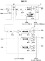
- FIG. 1 is a block diagram of the first embodiment.
- the difference in configuration from the first embodiment is the internal configuration of the spindle control circuit 21 and the opening position control circuit 30.
- a low-pass filter (LPF) 2104 is added to the spindle control circuit 21.
- the low-pass filter 2104 receives the SES and attenuates the high frequency component of the SES.
- the output signal of the low pass filter 2104 is input to the spindle controller 2101.
- a high pass filter (HPF) 3013 is added to the opening position control circuit 30.
- HPF high pass filter
- a high-pass filter 3013 receives SES and attenuates low frequency components of ES.
- the output signal of the high-pass filter 3013 is input to the X-axis compensator 3011 via the displacement conversion gain 3010.
- the spindle controller 2101 and the X-axis compensator 3011 are configured to perform control using a common SES.
- the spindle control controls the hologram recording medium 1 with respect to the SES variation of the same frequency component, while the opening position control controls the opening 214.
- the stability of the control is lowered and it takes time until both the two controls converge.
- the spindle control is performed based on the signal obtained by extracting the low-frequency component of the SES by the low-pass filter 2104, and the opening position control is performed based on the signal obtained by extracting the high-frequency component of the SES by the high-pass filter 3013. It was set as the structure which controls. As a result, the time can be shortened until both of the two controls converge.
- the low-pass filter 2104 is provided.
- the low-pass filter 2104 is not always essential. This is because the inertia of the hologram recording medium 1 is large and the band of the spindle control system cannot be increased compared to the opening position control. For this reason, since the frequency band to which the spindle control system responds is inevitably low, a configuration in which the low-pass filter 2104 is deleted from FIG. 12 is also conceivable. The same applies to the radial position control and the focus control since the inertia to be controlled is common.
- the opening position is controlled based on the result of detecting the displacement of the hologram recording medium 1.
- the opening position is controlled using a signal indicating the positional deviation of the opening 214 generated from the diffracted light during reproduction.
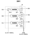
- FIG. 13 is a block diagram showing a recording / reproducing apparatus for a hologram recording medium for recording and / or reproducing digital information using holography.
- the same number is attached
- the difference in configuration from the first embodiment is that an internal configuration of the opening position control circuit 30 and a reproduction opening error signal generation circuit 32 are provided.
- the reproduction opening error signal generation circuit 32 uses a signal from the photodetector provided in the opening 214 to generate a signal AXES indicating the positional deviation in the X-axis direction with respect to the position of the opening 214 during reproduction.
- a signal AYES indicating a positional shift and a signal AZES indicating a positional shift in the Z-axis direction are generated.
- the opening position error signal at the time of reproduction is named as a general term for AXES, AYES, and AZES.
- AXES, AYES, and AZES are input to the opening position control circuit 30.
- an X-axis opening position error signal selector 3014 receives a signal AESEN indicating whether or not the reproduction opening position error signal is a valid period.
- the controller 80 receives a signal AESEN indicating whether or not the reproduction opening position error signal is a valid period.
- the AESEN signal is at a high level, it indicates that the reproduction opening position error signal (AXES, AYES, AZES) is a valid period.
- the X-axis opening position error signal selection selector 3014 receives the output signal of the displacement conversion gain 3010 and AXES, outputs AXES when the AESEN signal is high level, and outputs the displacement conversion gain 3010 when the AESEN signal is low level. Output a signal.
- the Y-axis opening position error signal selector 3024 receives RES and AYES, outputs AYES when the AESEN signal is high level, and outputs RES when the AESEN signal is low level.
- the Z-axis opening position error signal selector 3034 receives FES and AZES, outputs AZES when the AESEN signal is high level, and outputs FES when the AESEN signal is low level.
- the opening position control when the reproduction opening position error signal is not valid (when the AESEN signal is at a low level), the opening position control is the same as in the first embodiment. On the other hand, when the reproduction opening position error signal is valid (when the AESEN signal is at a high level), the opening position control is performed based only on the reproduction opening position error signal.
- the opening position can be controlled based on the information on the positional deviation generated from the diffracted light during reproduction, the influence of the displacement of the hologram recording medium 1 when disturbance such as vibration is applied during reproduction. Can be canceled and the reproduction performance can be further improved. Further, since the opening position control is performed based on the result of detecting the displacement of the hologram recording medium 1 at the time of recording, the influence of the displacement of the hologram recording medium 1 when a disturbance such as vibration is applied at the time of recording can be canceled.
- the opening position is controlled based on the result of detecting the displacement of the hologram recording medium 1.
- the acceleration applied to the hologram recording apparatus 10 is detected, and the opening position is controlled based on the detected acceleration.
- the present embodiment will be described as a modification of the third embodiment.
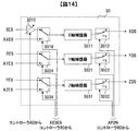
- FIG. 15 is a block diagram showing a recording / reproducing apparatus for a holographic recording medium for recording and / or reproducing digital information using holography.
- the same number is attached
- the difference in configuration from the third embodiment is that the internal configuration of the opening position control circuit 30 and the acceleration detection sensor 18 are provided.
- the acceleration detection sensor 18 individually measures accelerations in the X-axis, Y-axis, and Z-axis directions applied to the hologram recording apparatus 10, and outputs voltages proportional to the respective axis directions as ACX, ACY, and ACZ signals.
- the X-axis compensator 3011 receives the AXES signal indicating the positional deviation in the X-axis direction of the opening 214 during reproduction and outputs a drive signal.
- the X-axis adder 3015 outputs a signal obtained by adding the output signal of the X-axis compensator 3011 and the ACCX signal indicating the detected acceleration in the X-axis direction.
- the X-axis acceleration control selector 3016 receives the ACCX signal and the output signal of the X-axis adder 3015, outputs ACCX when the AESEN signal is low, and outputs the X-axis adder 3015 when the AESEN signal is high. Output a signal.
- the opening position control is performed based on the ACCX signal indicating the detected acceleration in the X-axis direction.
- the reproduction opening position error signal is valid (when the AESEN signal is at a high level)
- opening position control based on the reproduction opening position error signal and the ACCX signal is performed.
- the Y-axis compensator 3021 receives the AYES signal, and the output signal and the ACCY signal are added by the Y-axis adder 3025.
- the Y-axis acceleration control selector 3016 receives the ACCY signal and the output signal of the Y-axis adder 3025, outputs ACCY when the AESEN signal is low level, and outputs the Y-axis adder 3025 when the AESEN signal is high level. Output a signal.
- the Z-axis compensator 3031 receives the AZES signal, and the output signal and the ACCZ signal are added by the Z-axis adder 3035.
- the Z-axis acceleration control selector 3036 receives the ACCZ signal and the output signal of the Z-axis adder 3035, outputs ACCZ when the AESEN signal is low level, and outputs the Z-axis adder 3035 when the AESEN signal is high level. Output a signal.
- the acceleration applied to the hologram recording / reproducing apparatus 10 can be detected, and the opening position can be controlled based on the detected acceleration.
- the acceleration feedforward control is additionally performed on the feedback control system based on the reproduction opening position error signal.
- robustness against disturbance can be improved.
- the present embodiment has been described as a modification of the third embodiment where a reproduction opening position error signal is used.
- the reproduction opening position error signal is not used, the same control as when the reproduction opening position error signal is not valid (when the AESEN signal is at the low level) may be performed. That is, the opening position control based on the acceleration can be performed by generating the drive signal based on the detected acceleration.
- the direction of displacement by the spindle motor 50, the radial transport unit 51, and the Z stage 52 that changes the position on the hologram recording medium 1 irradiated with the signal light and / or the reference light is set at the opening 214.
- the configuration coincides with the drive shaft (x, y, z).
- a present Example is a modification in case this does not correspond.
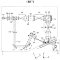
- FIG. 17 shows an optical system configuration of the pickup 11 and the reproduction reference light optical system 12 in the hologram recording / reproduction apparatus 10 in the present embodiment.
- the signal light 206 collected by the objective lens 215 with respect to the hologram recording medium 1 is incident at an angle rather than a right angle. That is, the hologram recording medium 1 is installed obliquely with respect to the first embodiment.
- the components of the pickup 11 and the reproducing reference beam optical system 12 and the components of the hologram recording / reproducing apparatus 10 are the same as those in the first embodiment.
- the direction of change of the irradiation position by the spindle motor 50 is the ⁇ axis
- the direction of change of the irradiation position by the radial transport unit 51 is the r axis
- the direction of change of the irradiation position by the Z stage 52 is the f axis.
- the position of the opening 214 in this embodiment can be changed along the three drive axes (x, y, z). Further, the position of the hologram recording medium 1 can be changed along the three drive axes (r, ⁇ , f).
- the actuator 230 capable of adjusting the position of the opening 214 in this embodiment is composed of an electromagnetic actuator and a stepping motor (both not shown), and (x, z) movement in two axes by the electromagnetic actuator, and y by the stepping motor.
- the axis is moved.
- the movement of the opening 214 in the y-axis direction takes longer than the movement in the x-axis direction and the movement in the z-axis direction due to the configuration.
- the frequency of changing the irradiation position in the direction of the ⁇ axis by the spindle motor 50 is greater in the radial direction conveyance unit 51.
- the frequency of changing the irradiation position in the r-axis direction is set higher.
- the spindle motor 50 is moved a plurality of times to record a hologram in an arc shape with the same radius on the hologram recording medium 1, and then the radial transport unit 51 is driven to change the radius again.
- the rotation motor 50 is driven to drive the hologram recording medium 1 at a speed higher than the speed at which the radial conveyance unit 51 is driven to move the hologram recording medium 1 by the distance between the books.
- the speed of moving by the distance between books is faster.
- the hologram recording medium 1 is in contact with the rotary motor 50 and rotates integrally with the rotary shaft. For this reason, the load applied to the rotary motor 50 is only the hologram recording medium 1.
- the radial transport unit 51 since the radial transport unit 51 is in contact with the rotary motor 50, the load applied to the radial transport unit 51 is the rotary motor 50 and the hologram recording medium 1. That is, the radial conveyance unit 51 is driven in a state where the weight of the rotary motor 50 is applied. As a result, the above speed difference occurs.
- the frequency of changing the irradiation position in the ⁇ -axis direction by the spindle motor 50 is greater by the radial transport unit 51.
- the transfer speed of recording or reproduction can be performed at a high speed.
- the opening 214 may be moved in the x-axis direction and the z-axis direction.
- the opening 214 must be moved in the r-axis direction. Since the x-axis direction and the z-axis direction that can be driven by the electromagnetic actuator are shorter, the movement in the ⁇ -axis direction is more advantageous from the viewpoint of the movement time of the opening 214 accompanying the change of the irradiation position.
- the r-axis coincides with the drive axis (y-axis) having the longest movement time among the three drive axes of the opening 214.
- a series of information recording processing or a series of information on the hologram recording medium 1 is performed.
- the accumulated time of the movement time of the opening 214 can be minimized.
- the three drive axes (x, y, z) of the opening 214 do not coincide with the three drive axes (r, ⁇ , f) that change the irradiation position of the hologram recording medium 1.
- the movement direction (r-axis) by the radial transport unit 51 that can move only at the lowest speed in moving the irradiation position and one of the three drive shafts of the opening 214 (more specifically, three of the opening 214) It is desirable to match the drive axis having the longest movement time among the two drive axes. Thereby, the transfer speed of recording or reproduction can be performed at high speed.
- the spindle control circuit 21, the radial conveyance control circuit 24, the focus control circuit 27, and the opening position control circuit 30 in the above embodiment are control circuits that constitute a feedback control system as described with reference to FIG. .
- it may be a control circuit that constitutes a two-degree-of-freedom control system having feed-forward control in addition to feedback control.
- the radial transport unit 51 in the first embodiment is used as a mechanism for controlling the light beam irradiated from the pickup 11 and the cure optical system 13 to be irradiated to a predetermined position of the hologram recording medium.
- the hologram recording medium 1 is transported.
- the mechanism for sharing the irradiation position of the light beam is not limited to this.
- the hologram recording medium may be fixed, and an optical system including the pickup 11 and the cure optical system 13 may be conveyed.
- the mechanism for transporting the optical system functions as means for changing the position on the hologram recording medium 1 to which the signal light and / or the reference light is irradiated.
- the present invention can be similarly applied if a sensor that detects the position of the optical system is used instead of detecting the position of the hologram recording medium 1.
- the rotation angle detection sensor 14, the radial position detection sensor 15, and the focus detection sensor 17 in the above embodiment detect information related to the position of the hologram recording medium 1 with reference to the position of the optical system including the pickup 11.
- these sensors can be rephrased as a detection unit capable of detecting information on the relative positions of the detection units and the hologram recording medium 1.
- Each detection unit can also be referred to as a detection unit that can detect information on the relative position between the objective lens 215 and the hologram recording medium 1.
- the present invention can be applied to a hologram recording / reproducing apparatus that uses signal light or diffracted light as parallel light without using the objective lens 215.
- the optical system and the hologram recording medium 1 can be used.
- it can be referred to as a detection unit capable of detecting information on relative positions.
- the detection unit capable of detecting information related to the relative position may not necessarily detect the position directly.
- a sensor for detecting the relative speed between the optical system and the hologram recording medium 1 may be provided, the position may be calculated by integrating the detected speed, and the position may be replaced with the position in the above embodiment.
- a sensor for detecting acceleration may be provided, the position may be calculated from the detected acceleration, and the position may be replaced with the position of the above-described embodiment.
- the position may be directly added to the control circuit in the opening position control circuit 30 without being converted into the position.
- the information on the detected position does not necessarily have to be converted into the position, and is characterized in that the position of the opening 214 is controlled based on the information on the detected position.
- the opening 214 has three drive shafts (x, y, z) by the actuator 230, but may have only one of the drive shafts.
- the opening 214 may be configured to be driven only in the x axis.
- the hologram recording / reproducing apparatus 10 of the present invention is configured to perform both information recording and information reproducing.
- the present invention can be similarly applied to a recording-dedicated apparatus or a reproduction-dedicated apparatus. It is.
- the photodetector 226 is unnecessary, and in the case of a reproduction-only device, the spatial light modulator 212 is not required.
- the light passing through the opening 214 whose position is changed by opening position control is signal light in the case of a recording-only device, and diffracted light in the case of a reproduction-only device.
- the present invention is not limited to the above-described embodiments, and includes various modifications in addition to the above-described modifications.
- the above-described embodiments have been described in detail for easy understanding of the present invention, and are not necessarily limited to those having all the configurations described.
- a part of the configuration of one embodiment can be replaced with the configuration of another embodiment, and the configuration of another embodiment can be added to the configuration of one embodiment.
- each of the above-described configurations, functions, processing units, processing means, and the like may be realized by hardware by designing a part or all of them with, for example, an integrated circuit.
- Each of the above-described configurations, functions, and the like may be realized by software by interpreting and executing a program that realizes each function by the processor.
- Information such as programs, tables, and files that realize each function can be stored in a memory, a hard disk, a recording device such as an SSD (Solid State Drive), or a recording medium such as an IC card, an SD card, or a DVD.
- control lines and information lines indicate what is considered necessary for the explanation, and not all the control lines and information lines on the product are necessarily shown. Actually, it may be considered that almost all the components are connected to each other.
- SYMBOLS 1 DESCRIPTION OF SYMBOLS 1 ... Hologram recording medium 10 ... Hologram recording / reproducing apparatus 11 ... Pickup 12 ... Reproduction reference light optical system 13 ... Cure optical system 14 ... Rotation angle detection sensor 15 ... Radius position detection sensor 17 ... Focus detection sensor 30 ... Opening position control circuit DESCRIPTION OF SYMBOLS 31 ... Opening position drive circuit 50 ... Spindle motor 51 ... Radial direction conveyance part 52 ... Z stage 201 ... Light source 206 ... Signal light 207 ... Reference light 212 ... Spatial light modulator 214 ... Opening part 215 ... Objective lens 226 ... Optical detector 230 ... Actuator 3010 ... Displacement conversion gain 3011 ... X-axis compensator 3012 ... X-axis control switch 3021 ... Y-axis compensator 3022 ... Y-axis control switch 3031 ... Z-axis compensator 3032 ... Z-axis control switch
Landscapes
- Physics & Mathematics (AREA)
- General Physics & Mathematics (AREA)
- Optics & Photonics (AREA)
- Holo Graphy (AREA)
- Optical Recording Or Reproduction (AREA)
Abstract
La présente invention concerne un appareil d'enregistrement/de reproduction d'hologramme qui permet d'obtenir un enregistrement préféré et/ou une reproduction préférée sur un support d'enregistrement d'hologramme. Un exemple de solution est un appareil d'enregistrement/de reproduction d'hologramme qui enregistre des informations par formation d'un hologramme sur un support d'enregistrement d'hologramme par l'intermédiaire de l'interférence entre une lumière de signal et une lumière de référence et/ou qui reproduit des informations par exposition d'un hologramme formé sur le support d'enregistrement d'hologramme à la lumière de référence. L'appareil d'enregistrement/de reproduction d'hologramme comprend : un système optique destiné à exposer le support d'enregistrement d'hologramme à la lumière de signal et/ou à la lumière de référence ; une ouverture qui laisse passer la lumière de signal et/ou une lumière diffractée générée lorsque l'hologramme est exposé au rayonnement de la lumière de référence ; une unité de commande de position d'ouverture destinée à commander la position de l'ouverture ; une unité de changement de position d'exposition à un rayonnement destinée à changer une position d'exposition à un rayonnement au niveau de laquelle le support d'enregistrement d'hologramme est exposé au rayonnement de la lumière de signal ou de la lumière de référence ; une unité de commande de position d'exposition à un rayonnement destinée à commander l'unité de changement de position d'exposition à un rayonnement ; et une unité de détection destinée à détecter des informations relatives à la position soit du support d'enregistrement d'hologramme, soit du système optique, l'unité de commande de position d'ouverture commandant la position de l'ouverture sur la base d'un signal de sortie provenant de l'unité de détection.
Priority Applications (1)
| Application Number | Priority Date | Filing Date | Title |
|---|---|---|---|
| PCT/JP2014/079520 WO2016072004A1 (fr) | 2014-11-07 | 2014-11-07 | Appareil d'enregistrement/de reproduction d'hologramme |
Applications Claiming Priority (1)
| Application Number | Priority Date | Filing Date | Title |
|---|---|---|---|
| PCT/JP2014/079520 WO2016072004A1 (fr) | 2014-11-07 | 2014-11-07 | Appareil d'enregistrement/de reproduction d'hologramme |
Publications (1)
| Publication Number | Publication Date |
|---|---|
| WO2016072004A1 true WO2016072004A1 (fr) | 2016-05-12 |
Family
ID=55908756
Family Applications (1)
| Application Number | Title | Priority Date | Filing Date |
|---|---|---|---|
| PCT/JP2014/079520 Ceased WO2016072004A1 (fr) | 2014-11-07 | 2014-11-07 | Appareil d'enregistrement/de reproduction d'hologramme |
Country Status (1)
| Country | Link |
|---|---|
| WO (1) | WO2016072004A1 (fr) |
Citations (5)
| Publication number | Priority date | Publication date | Assignee | Title |
|---|---|---|---|---|
| JPH06274914A (ja) * | 1993-03-23 | 1994-09-30 | Ricoh Co Ltd | 光情報記録再生装置 |
| JP2002222522A (ja) * | 2001-01-24 | 2002-08-09 | Matsushita Electric Ind Co Ltd | 情報ディスク記録再生装置、及び情報ディスク記録再生装置の振動検出方法 |
| WO2014083619A1 (fr) * | 2012-11-27 | 2014-06-05 | 日立コンシューマエレクトロニクス株式会社 | Dispositif d'enregistrement et de lecture d'informations optiques, et procédé d'enregistrement et de lecture d'informations optiques |
| WO2014097412A1 (fr) * | 2012-12-19 | 2014-06-26 | 日立コンシューマエレクトロニクス株式会社 | Appareil de lecture d'informations optiques et procédé de lecture d'informations optiques |
| WO2014167659A1 (fr) * | 2013-04-10 | 2014-10-16 | 日立コンシューマエレクトロニクス株式会社 | Enregistrement d'informations optiques et dispositif de reconstruction |
-
2014
- 2014-11-07 WO PCT/JP2014/079520 patent/WO2016072004A1/fr not_active Ceased
Patent Citations (5)
| Publication number | Priority date | Publication date | Assignee | Title |
|---|---|---|---|---|
| JPH06274914A (ja) * | 1993-03-23 | 1994-09-30 | Ricoh Co Ltd | 光情報記録再生装置 |
| JP2002222522A (ja) * | 2001-01-24 | 2002-08-09 | Matsushita Electric Ind Co Ltd | 情報ディスク記録再生装置、及び情報ディスク記録再生装置の振動検出方法 |
| WO2014083619A1 (fr) * | 2012-11-27 | 2014-06-05 | 日立コンシューマエレクトロニクス株式会社 | Dispositif d'enregistrement et de lecture d'informations optiques, et procédé d'enregistrement et de lecture d'informations optiques |
| WO2014097412A1 (fr) * | 2012-12-19 | 2014-06-26 | 日立コンシューマエレクトロニクス株式会社 | Appareil de lecture d'informations optiques et procédé de lecture d'informations optiques |
| WO2014167659A1 (fr) * | 2013-04-10 | 2014-10-16 | 日立コンシューマエレクトロニクス株式会社 | Enregistrement d'informations optiques et dispositif de reconstruction |
Similar Documents
| Publication | Publication Date | Title |
|---|---|---|
| JP5707147B2 (ja) | 光情報再生方法および光情報再生装置 | |
| JP5183667B2 (ja) | 再生装置および再生方法 | |
| JP5753768B2 (ja) | 光情報記録装置、光情報再生装置、光情報記録再生装置、光情報記録方法、光情報再生方法および光情報記録再生方法 | |
| JP5581111B2 (ja) | 光情報再生装置および光情報再生方法 | |
| JP4969558B2 (ja) | 光情報再生装置、光情報記録再生装置 | |
| CN103123792B (zh) | 光信息记录再现装置和方法 | |
| JPWO2014167659A1 (ja) | 光情報記録再生装置 | |
| JPWO2014199504A1 (ja) | 光情報記録再生装置、及び調整方法 | |
| WO2016072004A1 (fr) | Appareil d'enregistrement/de reproduction d'hologramme | |
| JP6078636B2 (ja) | ホログラム記録再生装置及びホログラム再生方法 | |
| JP5816132B2 (ja) | ホログラム用光ピックアップ装置及び光情報記録再生装置 | |
| JP2017021881A (ja) | 光情報記録装置、光情報記録方法および光情報記録媒体 | |
| JP6093778B2 (ja) | 記録再生装置及び記録媒体 | |
| JP5993956B2 (ja) | 光情報記録再生装置および光情報記録再生方法 | |
| JP2015204121A (ja) | 光情報装置 | |
| US20170162221A1 (en) | Optical Information Recording/Reproduction Device and Optical Information Recording/Reproduction Method | |
| JP2016091572A (ja) | ホログラム再生装置、ホログラム再生方法 | |
| WO2014097412A1 (fr) | Appareil de lecture d'informations optiques et procédé de lecture d'informations optiques | |
| JP2009151901A (ja) | 光ディスク装置及び光情報記録方法 | |
| JP2017004576A (ja) | 光情報記録再生装置および光情報記録再生方法 | |
| WO2015075827A1 (fr) | Dispositif de reconstruction d'hologramme et procédé de reconstruction d'hologramme | |
| JP2016009508A (ja) | 光情報再生装置、光情報再生方法 | |
| JP2015130215A (ja) | 光情報記録装置および光情報記録方法 | |
| WO2014083944A1 (fr) | Dispositif de lecture et/ou d'enregistrement d'hologramme | |
| JP2018005966A (ja) | 情報記録再生装置及び情報記録再生方法 |
Legal Events
| Date | Code | Title | Description |
|---|---|---|---|
| 121 | Ep: the epo has been informed by wipo that ep was designated in this application |
Ref document number: 14905385 Country of ref document: EP Kind code of ref document: A1 |
|
| NENP | Non-entry into the national phase |
Ref country code: DE |
|
| 122 | Ep: pct application non-entry in european phase |
Ref document number: 14905385 Country of ref document: EP Kind code of ref document: A1 |
|
| NENP | Non-entry into the national phase |
Ref country code: JP |