WO2016072460A1 - Système de culture cellulaire et récipient de culture cellulaire - Google Patents
Système de culture cellulaire et récipient de culture cellulaire Download PDFInfo
- Publication number
- WO2016072460A1 WO2016072460A1 PCT/JP2015/081200 JP2015081200W WO2016072460A1 WO 2016072460 A1 WO2016072460 A1 WO 2016072460A1 JP 2015081200 W JP2015081200 W JP 2015081200W WO 2016072460 A1 WO2016072460 A1 WO 2016072460A1
- Authority
- WO
- WIPO (PCT)
- Prior art keywords
- medium
- cell culture
- culture container
- supply
- temporary holding
- Prior art date
- Legal status (The legal status is an assumption and is not a legal conclusion. Google has not performed a legal analysis and makes no representation as to the accuracy of the status listed.)
- Ceased
Links
- 0 *=*1CCCC1 Chemical compound *=*1CCCC1 0.000 description 1
- OHDLZTDSTWANIC-UHFFFAOYSA-N C[I]1CCCC1 Chemical compound C[I]1CCCC1 OHDLZTDSTWANIC-UHFFFAOYSA-N 0.000 description 1
Images




















Classifications
-
- C—CHEMISTRY; METALLURGY
- C12—BIOCHEMISTRY; BEER; SPIRITS; WINE; VINEGAR; MICROBIOLOGY; ENZYMOLOGY; MUTATION OR GENETIC ENGINEERING
- C12M—APPARATUS FOR ENZYMOLOGY OR MICROBIOLOGY; APPARATUS FOR CULTURING MICROORGANISMS FOR PRODUCING BIOMASS, FOR GROWING CELLS OR FOR OBTAINING FERMENTATION OR METABOLIC PRODUCTS, i.e. BIOREACTORS OR FERMENTERS
- C12M41/00—Means for regulation, monitoring, measurement or control, e.g. flow regulation
- C12M41/44—Means for regulation, monitoring, measurement or control, e.g. flow regulation of volume or liquid level
-
- C—CHEMISTRY; METALLURGY
- C12—BIOCHEMISTRY; BEER; SPIRITS; WINE; VINEGAR; MICROBIOLOGY; ENZYMOLOGY; MUTATION OR GENETIC ENGINEERING
- C12M—APPARATUS FOR ENZYMOLOGY OR MICROBIOLOGY; APPARATUS FOR CULTURING MICROORGANISMS FOR PRODUCING BIOMASS, FOR GROWING CELLS OR FOR OBTAINING FERMENTATION OR METABOLIC PRODUCTS, i.e. BIOREACTORS OR FERMENTERS
- C12M23/00—Constructional details, e.g. recesses, hinges
- C12M23/40—Manifolds; Distribution pieces
-
- C—CHEMISTRY; METALLURGY
- C12—BIOCHEMISTRY; BEER; SPIRITS; WINE; VINEGAR; MICROBIOLOGY; ENZYMOLOGY; MUTATION OR GENETIC ENGINEERING
- C12M—APPARATUS FOR ENZYMOLOGY OR MICROBIOLOGY; APPARATUS FOR CULTURING MICROORGANISMS FOR PRODUCING BIOMASS, FOR GROWING CELLS OR FOR OBTAINING FERMENTATION OR METABOLIC PRODUCTS, i.e. BIOREACTORS OR FERMENTERS
- C12M23/00—Constructional details, e.g. recesses, hinges
- C12M23/34—Internal compartments or partitions
-
- C—CHEMISTRY; METALLURGY
- C12—BIOCHEMISTRY; BEER; SPIRITS; WINE; VINEGAR; MICROBIOLOGY; ENZYMOLOGY; MUTATION OR GENETIC ENGINEERING
- C12M—APPARATUS FOR ENZYMOLOGY OR MICROBIOLOGY; APPARATUS FOR CULTURING MICROORGANISMS FOR PRODUCING BIOMASS, FOR GROWING CELLS OR FOR OBTAINING FERMENTATION OR METABOLIC PRODUCTS, i.e. BIOREACTORS OR FERMENTERS
- C12M29/00—Means for introduction, extraction or recirculation of materials, e.g. pumps
-
- C—CHEMISTRY; METALLURGY
- C12—BIOCHEMISTRY; BEER; SPIRITS; WINE; VINEGAR; MICROBIOLOGY; ENZYMOLOGY; MUTATION OR GENETIC ENGINEERING
- C12M—APPARATUS FOR ENZYMOLOGY OR MICROBIOLOGY; APPARATUS FOR CULTURING MICROORGANISMS FOR PRODUCING BIOMASS, FOR GROWING CELLS OR FOR OBTAINING FERMENTATION OR METABOLIC PRODUCTS, i.e. BIOREACTORS OR FERMENTERS
- C12M29/00—Means for introduction, extraction or recirculation of materials, e.g. pumps
- C12M29/10—Perfusion
Definitions
- the present invention relates to a cell culture system and a cell culture container that can automatically replace the medium in the cell culture container.
- the present invention has been made in view of the above-described circumstances, and it is possible to easily and automatically replace the medium in the cell culture container in the cell culture space, and to make a system trouble by making the system simple.
- a cell culture system and a cell culture container that can reduce the risk of the occurrence of the above.
- One aspect of the present invention is a medium storage means for holding a medium for culturing cells, a holding space connected to the medium storage means and temporarily holding the medium supplied from the medium storage means, A temporary holding means having a discharge port for discharging the medium, a medium supply means connected to the discharge port of the temporary holding means and supplying the medium discharged from the temporary holding means to a cell culture container, and the cells
- the supply means is a cell culture system provided with a flow path capable of intermittently supplying a medium from the temporary holding means to the cell culture container according to the principle of siphon.
- a solution such as a medium can be intermittently supplied to the cell culture container with a simple configuration.
- Another aspect of the present invention is a medium storage means for holding a medium for culturing cells, a holding space connected to the medium storage means and temporarily holding the medium supplied from the medium storage means, A temporary holding means having a discharge port for discharging the medium; a medium supply means connected to the discharge port of the temporary holding means and supplying the medium discharged from the temporary holding means to the cell culture container; A medium discharge means for discharging a medium from the cell culture container, wherein the cell culture container is connected to the medium supply means at a position lower than the medium supply means in the direction of gravity,
- the culture medium supply means is a cell culture system including a supply gate that opens a flow path when the culture medium in the holding space reaches a predetermined amount.
- the temporary holding means employs a gate that opens and closes according to the amount of the medium in the medium, so that a solution such as a medium can be intermittently supplied to the cell culture container with a simple configuration.
- the medium supply unit is configured so that the medium before being supplied to the cell culture container is positioned above the discharge port of the temporary holding unit in the direction of gravity and has a maximum height in the direction of gravity of the holding space. You may provide the flow path which lets a lower position pass.
- the discharge port is disposed on a side surface of the temporary holding unit at a predetermined height from the bottom surface of the temporary holding unit, and the medium supply unit is disposed outside the temporary holding unit from the discharge port.
- a flow path may be formed.
- the medium supply means forms a flow path from the discharge port of the temporary holding means to the inside of the temporary holding means, and is connected to the discharge port of the temporary holding means.
- the opposite end may have an opening in the vicinity of a gap from the bottom surface of the temporary holding means.
- the supply gate opens the flow path when the medium in the holding space reaches a predetermined weight or when the upper surface of the medium in the holding space reaches a predetermined height. May be.
- the cell culture container may include a discharge port for discharging the medium to the outside when the height of the inner medium upper surface reaches a predetermined height. This makes it possible to automatically supply and discharge a solution such as a medium to and from the cell culture container with a simple configuration.
- a supply speed adjusting means for controlling a supply speed of the medium supplied from the medium storage means to the temporary holding means may be provided. This makes it possible to arbitrarily set the cycle for intermittently supplying the medium to the cell culture container.
- Another aspect of the present invention is a cell culture container including a supply port for supplying a culture medium, a discharge port for discharging the culture medium, and a tubular member connected to the discharge port, the tubular member Is a cell culture container that forms a flow path capable of intermittently discharging the medium in the cell culture container according to the principle of siphon.
- the tubular member may form a flow path that passes through a position above the discharge port in the direction of gravity and lower than the maximum height in the direction of gravity of the space in the cell culture vessel.
- the said discharge port is arrange
- the said tubular member is the said cell culture container from the said discharge port.
- a channel may be formed outside.
- the tubular member forms a flow path from the outlet to the inside of the cell culture container, and an end opposite to an end connected to the outlet of the tubular member is the cell culture.
- You may have an opening part in the vicinity which opened the gap
- Another aspect of the present invention is a cell culture system comprising the cell culture container described above and a medium supply means for supplying a medium from the supply port of the cell culture container.
- the present invention it is possible to change the medium even when the worker is not present, and the number of times the worker enters the work space can be reduced. This can reduce labor and costs such as changing to disposable work clothes, and can reduce the risk of contamination of the cell culture system by bacteria and the like. Moreover, since the system configuration is simple, the risk of system errors can be reduced, and the risk of affecting the culture conditions due to errors can be avoided.
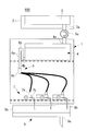
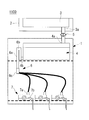
- a cell culture system 100 according to the present embodiment is a system having the configuration shown in FIGS. 1A and 1B, and is a system for exchanging a medium in a cell culture container (culture container) installed in an incubator.
- the medium storage means 3 is installed outside the incubator 1 and stores the medium (cell culture solution) inside.
- a temperature control means 2 is provided in order to maintain the temperature of the culture medium at a temperature suitable for storage (for example, 4 ° C.).
- the medium storage means 3 is connected to a temporary holding means 4 installed inside the incubator 1 via a tubular member (tube or the like). Since the culture medium storage means 3 is installed at a position above the temporary holding means 4 in the direction of gravity, the culture medium in the culture medium storage means 3 is supplied to the temporary holding means 4 via a tubular member (tube or the like) by gravity. The The medium supplied to the temporary holding means 4 is held in a space (holding space) in the temporary holding means 4 and warmed to a temperature in an incubator (for example, 37 ° C.) that is a temperature suitable for cell culture.
- a temperature in an incubator for example, 37 ° C.
- the tubular member connecting the medium storage means 3 and the temporary holding means 4 is provided with a supply speed adjusting means 5, and the medium flow rate in the tubular member is controlled to control the flow rate of the medium flowing from the medium storage means 3 to the temporary holding means 4.
- the supply rate of the medium can be adjusted.
- the medium heated to a temperature suitable for cell culture (for example, 37 ° C.) by the temporary holding means 4 is supplied to the cell culture container 7 through the medium supply means 6 in the incubator 1.
- the temporary holding means 4 includes a supply port 4a through which a culture medium is supplied from the culture medium holding means 3 via a tubular member, and a discharge port 4b through which the culture medium is discharged to the culture medium supply means 6.
- the installation position of the supply port 4a is arbitrary, it is preferable that the culture medium installed and supplied in the upper part of the temporary holding means 4 is dripped in internal space. Thereby, the back flow of the medium can be prevented, and the medium in the medium storage means 3 can be prevented from being contaminated (contamination occurs).
- the installation place of the discharge port 4b is preferably a place where the internal medium can be discharged to the end, that is, the bottom surface of the temporary holding means 4 or the lower part of the side surface.
- the medium supply means 6 includes a siphon mechanism 6a (medium intermittent supply mechanism).
- the siphon mechanism 6 a is connected to the discharge port 4 b of the temporary holding means 4.
- the flow path as shown in FIGS. 1A and 1B is folded. That is, the flow path of the siphon mechanism 6a extends from the discharge port 4b of the temporary holding means 4 upward to a predetermined height in the direction of gravity, and then turns back to extend downward in the direction of gravity.
- the predetermined height at which the flow path of the siphon mechanism 6a reaches upward in the direction of gravity is set to a position lower than the maximum height at which the medium retained in the temporary holding means 4 can reach in the direction of gravity (hereinafter referred to as “the height of the medium”).
- This set height is referred to as “folding point 6b”).
- folding point 6b the medium in the temporary holding means 4 is discharged through the flow path of the siphon mechanism 6a according to the siphon principle.
- the discharge continues until the height of the medium in the temporary holding means 4 reaches the discharge port 4b of the temporary holding means 4.
- the height of the medium in the temporary holding means 4 starts to rise due to the medium supplied from the medium storage means 3, and discharge occurs again when the position reaches a position higher than the turn-around point 6b of the flow path of the siphon mechanism 6a. repeat.
- the flow path of the siphon mechanism 6a rises upward in the direction of gravity from the discharge port 4b side of the temporary medium holding means 4 to the folding point 6b, passes through the folding point 6b, and descends downward in the direction of gravity to reach the branching means 6c. .
- a plurality of tubular members (tubes or the like) branch from the branching means 6c. The plurality of branched tubular members are connected to different cell culture containers 7 to supply a medium.
- the cell culture container 7 has a supply port 7a connected to the tubular member of the medium supply means 6, and a discharge port 7b for discharging the medium outside the cell culture container.
- the discharge port 7b is arranged on the side surface of the cell culture container 7, and when the amount of medium (height of the medium) in the cell culture container exceeds a certain value, the medium is discharged to the medium discharge means 8 through the discharge port 7b. ing.
- the amount of the medium retained in the cell culture container 7 is determined by the installation height of the discharge port 7b.
- the installation position of the supply port 7a is arbitrary, but the conversion efficiency of the medium can be increased by separating the distance from the discharge port 7b as much as possible.
- the medium that is installed and supplied at the top of the cell culture container 7 is dropped inside the cell culture container, the medium can be prevented from flowing back, and the medium supply means 6 and the temporary medium holding means that are arranged upstream of the system. 4. It is possible to prevent the medium in the medium storage means 3 from being contaminated (contamination occurs).
- the medium discharge means 8 includes a waste liquid holding means 8a.
- the waste liquid holding means 8a includes a waste liquid supply port 8b connected to the tubular member from the cell culture vessel 7, and a waste liquid discharge port 8c for discharging the medium outside the waste liquid holding means 8a.
- the waste liquid supply port 8b is installed on the upper surface of the waste liquid holding means 8a, and the medium supplied from the waste liquid supply port 8b is dropped in the space in the waste liquid holding means 8a and discharged through the waste liquid discharge port 8c. In this way, the medium is dropped in the space in the waste liquid holding means 8a, so that the back flow of the medium can be prevented and the inside of the cell culture container 7 can be prevented from being contaminated (contamination occurs). it can.
- the supply speed adjusting means 5 is disposed on a tubular member (tube or the like) that connects the discharge port 3a of the culture medium storage means 3 and the supply port 4a of the temporary holding means 4, and is deformed by applying an external force to the tubular member. By reducing the cross-sectional area of the cavity, the flow rate of the solution is limited to suppress the flow rate. Conversely, when the external force is released, the tubular member returns to its original state by the elastic force of the tubular member, and the flow velocity can be increased. As described above, the supply speed adjusting means 5 adjusts the flow rate of the solution flowing in the tubular member by the strength of the external force applied to the tubular member.
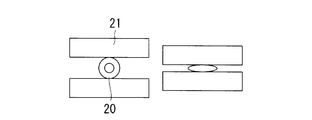
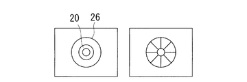
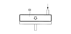
- FIGS. 2A to 2D Examples of how external force is applied to the tubular member by the supply speed adjusting means 5 are shown in FIGS. 2A to 2D.
- 2A shows an example in which the tubular member 20 is sandwiched by two plate-like members 21
- FIG. 2B shows an example in which the tubular member 20 passed through the through hole 23 is sandwiched by a plurality of spherical (or cylindrical) members 22
- FIG. 2D shows an example in which the inner diameter of the through hole 26 through the tubular member 20 is reduced and the tubular member is deformed.
- a liquid feed pump such as a peristaltic pump may be used as the supply speed adjusting means 5.
- the user of this system sets the system to a state where the supply rate of the culture medium is 0, that is, a state where the supply is stopped, by the supply rate adjusting means 5 and replenishes the culture medium storage means 3 with the culture medium.
- a cell culture container 7 containing a culture medium and cells is prepared.
- the supply port 7a of the cell culture container 7 is used as a tubular member of the medium supply means 6, and the discharge port 7b of the cell culture container 7 is used as a waste liquid through the tubular member. Connected to the waste liquid supply port 8b of the holding means 8a.
- the user first adjusts the supply speed adjusting means 5 to set the supply speed to an appropriate speed.
- the supply rate adjusting unit 5 releases the state where the supply rate is 0, the medium starts to drip in the temporary medium holding unit 4 due to gravity.
- the adjustment of the supply speed may be set to a predetermined speed, or may be adjusted to an appropriate supply speed while being visually observed by the user.
- a culture medium is supplied to the temporary culture medium holding means 4, and the medium level in the temporary culture medium holding means 4 rises (FIG. 3A).
- the level of the medium in the temporary medium holding means 4 becomes higher than the height of the turning point 6b of the medium supply means 6 (FIG. 3B)
- the medium in the temporary holding means 4 is discharged via the medium supply means 6 according to the principle of siphon.
- the discharge continues until the height of the medium in the temporary holding means 4 reaches the discharge port 4b of the temporary holding means 4, and the discharge stops (FIG. 3D). Thereafter, the height of the medium in the temporary holding means 4 starts to rise due to the medium supplied from the medium storage means 3, and the process of discharging again when reaching a position higher than the turning point 6b of the medium supply means 6 is repeated.
- the medium discharged from the temporary holding means 4 is supplied to the plurality of cell culture containers 7 via the branching means 6 c of the medium supply means 6.
- the medium exceeding the specified amount in the cell culture container 7 is discharged from the discharge port 7b of the cell culture container 7, and is discharged outside the incubator through the waste liquid holding means 8a.
- the old medium in the cell culture vessel 7 is replaced with a new medium, and the rate at which the medium deteriorates can be reduced.
- the siphon mechanism 6a may be formed of a tubular member (tube or the like) that forms a flow path. That is, the tubular member connected to the discharge port 4b of the temporary holding means 4 only needs to have a structure that extends upward in the direction of gravity to the height of the folding point 6b and then folds back and extends downward in the direction of gravity.
- the tubular member extending downward past the turning point 6b reaches the branching means 6c, and the plurality of tubular members branched from the branching means 6c are connected to different cell culture vessels 7 to supply the medium.
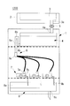
- the cell culture system 300 is a system having the configuration shown in FIGS. 4A and 4B and is a system for exchanging a medium in a cell culture container (culture container) installed in an incubator.
- the medium storage means 3 is installed outside the incubator 1 and stores the medium (cell culture solution) inside.
- a temperature control means 2 is provided in order to maintain the temperature of the culture medium at a temperature suitable for storage (for example, 4 ° C.).
- the medium storage means 3 is connected to a temporary holding means 4 installed inside the incubator 1 via a tubular member (tube or the like). Since the culture medium storage means 3 is installed at a position above the temporary holding means 4 in the direction of gravity, the culture medium in the culture medium storage means 3 is supplied to the temporary holding means 4 via a tubular member (tube or the like) by gravity. The The medium supplied to the temporary holding means 4 is warmed to a temperature in an incubator (for example, 37 ° C.) that is a temperature suitable for cell culture.
- the tubular member connecting the medium storage means 3 and the temporary holding means 4 is provided with a supply speed adjusting means 5, and the medium flow rate in the tubular member is controlled to control the flow rate of the medium flowing from the medium storage means 3 to the temporary holding means 4. The supply rate of the medium can be adjusted.
- the medium heated to a temperature suitable for cell culture (for example, 37 ° C.) by the temporary holding means 4 is supplied to the cell culture container 7 through the medium supply means 6 in the incubator 1.
- the temporary holding means 4 includes a supply port 4a through which a culture medium is supplied from the culture medium holding means 3 via a tubular member, and a discharge port 4b through which the culture medium is discharged to the culture medium supply means 6.
- the installation position of the supply port 4a is arbitrary, it is preferable that the culture medium installed and supplied in the upper part of the temporary holding means 4 is dripped in internal space. Thereby, the back flow of the medium can be prevented, and the medium in the medium storage means 3 can be prevented from being contaminated (contamination occurs).
- the installation place of the discharge port 4b is preferably the temporary holding means 4 that can discharge the internal culture medium to the end.
- the culture medium supply means 6 includes a supply gate 6d (medium intermittent supply mechanism) at the connection with the temporary culture medium holding means 4.
- the supply gate 6d is a means capable of opening and closing the flow path in accordance with the amount of the medium in the temporary holding means 4, and when the medium in the temporary medium holding means 4 exceeds a predetermined amount, the gate is opened and the medium from the temporary holding means 4 is opened. When the medium in the temporary holding means 4 is reduced to a predetermined amount, the gate is closed and the discharge of the medium from the temporary holding means 4 is blocked.
- the supply gate 6d is connected to the cell culture container 7 through a tubular member.
- the tubular member of the culture medium supply means 6 coming out from the supply gate 6d branches into a plurality of tubular members when reaching the branching means 6c.
- the plurality of branched tubular members are connected to different cell culture containers 7 to supply a medium.
- the cell culture container 7 has a supply port 7a connected to the tubular member of the medium supply means 6, and a discharge port 7b for discharging the medium outside the cell culture container.
- the discharge port 7b is arranged on the side surface of the cell culture container 7, and when the amount of medium (height of the medium) in the cell culture container exceeds a certain value, the medium is discharged to the medium discharge means 8 through the discharge port 7b. ing.
- the amount of the medium retained in the cell culture container is determined by the installation height of the discharge port 7b.
- the installation position of the supply port 7a is arbitrary, but the conversion efficiency of the medium can be increased by separating the distance from the discharge port 7b as much as possible.
- the medium discharge means 8 includes a waste liquid holding means 8a.
- the waste liquid holding means 8a includes a waste liquid supply port 8b connected to the tubular member from the cell culture vessel 7, and a waste liquid discharge port 8c for discharging the medium outside the waste liquid holding means 8a.
- the waste liquid supply port 8b is installed on the upper surface of the waste liquid holding means 8a, and the medium supplied from the waste liquid supply port 8b is dropped in the space in the waste liquid holding means 8a and discharged through the waste liquid discharge port 8c. In this way, the medium is dropped in the space in the waste liquid holding means 8a, so that the back flow of the medium can be prevented and the inside of the cell culture container 7 can be prevented from being contaminated (contamination occurs). it can.
- the supply speed adjusting means 5 is the same as that in the first embodiment.
- the supply gate 6d is a means capable of opening and closing the flow path in accordance with the amount of the medium in the temporary holding means 4, and has a configuration as shown in FIGS. 5A to 5D, for example.
- 5A and 5B are examples in which the flow path is blocked by the valve 31.
- FIG. The valve 31 is disposed at a position where the flow path is blocked by the elastic force when no force is applied.
- the pressure from the culture medium in the temporary holding means 4 exceeds the threshold value, the valve 31 is opened to open the flow path. Is opened, and the medium is discharged from the temporary holding means 4.
- the pressure applied to the valve 31 from the culture medium begins to decrease.
- FIG. 5A is an aspect in which the ring member 32 prevents the valve 31 from falling in the reverse direction of the flow path
- FIG. 5B is a view in which the valve 31 is reverse to the flow path by adopting a structure in which the flow path expands in the flow direction. There is a mode for preventing the body from falling in the direction.
- FIG. 5C and 5D are examples in which the flow path is blocked by the balls 33.
- FIG. 1 In a state where no force is applied to the ball 33, the ball 33 is arranged at a position to close the flow path by being pushed by the ring member 32 by an elastic member 34 (for example, a spring), but the pressure from the medium in the temporary holding means 4 Exceeds the threshold, the ball 33 is pushed in the flow direction to open the flow path, and the medium is discharged from the temporary holding means 4.
- the pressure applied to the ball 33 from the medium decreases, and when the pressure becomes lower than the threshold, the ball 33 returns to the position where the elastic member 34 closes the flow path, and the medium from the temporary holding means 4 is returned. Is blocked.
- FIG. 5C shows a mode in which the ball 33 is pressed against the ring member 32 to block the flow path
- FIG. 5D has a structure in which the flow path expands in the flow path direction, and the ball 33 is pressed against the narrowed flow path.
- the user of this system first sets the system to a state where the supply rate is zero, that is, the state where the supply is stopped, by the supply rate adjusting means 5, and replenishes the culture medium storage means 3 with the medium.
- a cell culture container 7 containing a culture medium and cells is prepared.
- the supply port 7a of the cell culture container 7 is used as a tubular member of the medium supply means 6, and the discharge port 7b of the cell culture container 7 is used as a waste liquid through the tubular member. Connected to the waste liquid supply port 8b of the holding means 8a.
- the user first adjusts the supply speed adjusting means 5 to set the supply speed to an appropriate speed.
- the supply rate adjusting unit 5 releases the state where the supply rate is 0, the medium starts to drip in the temporary medium holding unit 4 due to gravity.
- the adjustment of the supply speed may be set to a predetermined speed, or may be adjusted to an appropriate supply speed while being visually observed by the user.
- the medium is supplied to the temporary medium holding means 4, and the amount of medium in the temporary medium holding means 4 increases.
- the gate opens, and the medium in the temporary holding means 4 begins to be discharged through the medium supply means 6, and the temporary pressure applied to the supply gate 6d.
- the discharge continues until the pressure from the medium in the medium holding means 4 decreases to the threshold value, and when the pressure decreases to the threshold value, the discharge stops. Thereafter, the amount of the medium in the temporary holding means 4 starts to increase due to the medium supplied from the medium storage means 3, and discharge occurs again when the pressure from the medium in the temporary medium holding means 4 applied to the supply gate 4d exceeds the threshold value. Repeat the process.
- the medium discharged from the temporary holding means 4 is supplied to the plurality of cell culture containers 7 via the branching means 6 c of the medium supply means 6.
- the medium exceeding the specified amount in the cell culture container 7 is discharged from the discharge port 7b of the cell culture container 7, and is discharged outside the incubator through the waste liquid holding means 8a.
- the old medium in the cell culture vessel 7 is replaced with a new medium, and the rate at which the medium deteriorates can be reduced.
- FIGS. 6A to 6D Another aspect of the supply gate of this embodiment is shown in FIGS. 6A to 6D.
- 6A and 6B are examples in which the flow path is blocked by the valve 41.
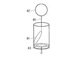
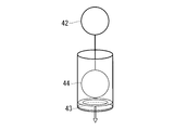
- FIG. The valve 41 is connected to the float 42 via a string-like member 45.
- the float 42 has a structure that floats on the upper surface of the medium in the temporary holding means 4. When the medium in the temporary holding means 4 increases, the height of the upper surface of the medium rises, and the float 42 rises accordingly. As the float 42 rises, tension is generated in the string-like member 45, and the valve 41 receives an upward force by the string-like member 45.
- the valve 41 When the height of the upper surface of the medium exceeds the threshold value, the valve 41 is opened to open the flow path, and the medium is discharged from the temporary holding means 4.
- the upper surface of the culture medium in the temporary holding means 4 starts to descend, and the float 42 also descends, whereby the tension of the string-like member 45 is reduced, and the valve 41 has a flow path by its elastic force (or gravity).
- the valve 41 Returning to the position where the medium is closed, the discharge of the medium from the temporary holding means 4 is blocked. Thereafter, when the amount of the culture medium in the temporary holding means 4 increases and the height of the upper surface of the culture medium exceeds the threshold value, the valve 41 is raised again to open the flow path.
- FIG. 6A is a mode in which the valve 41 is prevented from falling in the reverse direction of the flow path by the ring member 43
- FIG. 6B is a view in which the valve 41 is reverse to the flow path by adopting a structure in which the flow path narrows in the flow direction.
- 6C and 6D are examples in which the flow path is blocked by a ball 44 instead of the valve 41.
- FIG. 6C shows a mode in which the ball 44 is pressed against the ring member 43 to block the flow path
- FIG. 6D has a structure in which the flow path is narrowed in the flow path direction, and the ball 44 is pressed against the narrowed flow path.
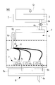
- the cell culture system 500 according to the present embodiment is different from the above embodiments in that it includes pressure load means 51 for applying pressure to the medium in the medium storage means 3.
- FIG. 7 is an example corresponding to the first embodiment, but the other embodiments are also the same.
- An example of the pressure loading means 51 is a means for sending gas into the culture medium storage means 3 by a pump. Thereby, the pressure of the air layer in the culture medium storage means 3 is increased, and an external pressure can be applied to the culture medium. It is preferable to use a sterilized gas to be fed into the culture medium storage means 3.
- gas (or liquid) is fed into the bag-like member 61, and pressure is applied to the culture medium with the bag having an increased volume.
- the member 62 may be used to block the air layer 63 and the medium, and a gas (or liquid) may be sent to the air layer 63 to apply pressure to the medium using the isolation member 62. This can reduce the risk of medium contamination. As shown in FIG.
- the weight 65 having a predetermined weight is placed on the upper portion of the separating member 64 for isolation.
- a constant pressure may be applied to the member 64.
- the medium holding means and the partition member are structured like a syringe cylinder and a pusher (plunger), respectively, and the partition member, which is a pusher (plunger), is mechanically moved to apply pressure to the medium inside the medium holding means. It is okay to spend.
- the movement of the partition member may be controlled by the control unit in a wired or wireless manner.
- the medium holding means has a cylindrical structure
- the partition wall member has a disk-like structure that fits on the inner wall of the cylindrical structure
- the screw structure that meshes with the inner wall of the cylindrical structure and the outer periphery of the disk-like structure.
- the pressure load means 51 is preferably controlled so that the pressure in the culture medium storage means 3 does not rise above a certain level.
- the culture medium storage unit 3 does not necessarily have to be installed at a higher position than the temporary holding unit 4.
- the temporary holding means 4 is not necessarily installed at a position higher than the medium supply means 6.
- the cell culture system 600 As shown in FIG. 9, the cell culture system 600 according to this embodiment is different from the above embodiments in that it includes negative pressure supply means 71 for applying a negative pressure to the discharge port 7 b of the cell culture container 7. ing. Other than that is the same as each said embodiment.
- FIG. 9 is an example corresponding to the first embodiment, but the other embodiments are also the same.
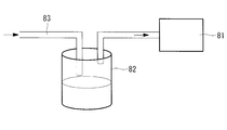
- Examples of the negative pressure supply means 71 include a means provided with a pump 81 and a waste liquid container 82 as shown in FIG.
- the suction port 83 of the negative pressure supply means 71 By connecting the suction port 83 of the negative pressure supply means 71 to the waste liquid discharge port 8b of the waste liquid holding means 8a, the inside of the waste liquid holding means 8a is set to a negative pressure, and the discharge port 7b of the cell culture vessel 7 is set to a negative pressure. It is possible to aspirate the culture medium from the container 7.
- a liquid feed pump such as a peristaltic pump may be used as a pump for the negative pressure supply means. In this case, a liquid feed pump may be installed on the tubular member of the suction port 83.
- the cell culture system 700 can be remotely operated wirelessly or wired by the control unit 19 in which the supply speed adjusting means 5 is installed outside the incubator. It has become. Other than that is the same as each said embodiment.
- FIG. 11 is an example corresponding to the first embodiment, but the other embodiments are also the same.
- the supply speed adjusting means 5 is capable of exchanging information with a control unit 19 installed outside the incubator by wireless or wired, and remotely supplies a solution such as a medium flowing in a tubular member (tube or the like).
- the flow rate can be controlled.
- the user remotely adjusts the supply speed adjusting means 5 by the control unit 19 to set the supply speed to an appropriate speed.
- the supply speed may be adjusted to a predetermined speed, or may be adjusted to an appropriate supply speed while monitoring the dropping speed with a monitoring system (not shown).
- the user can remotely start medium exchange at any timing during cell culture or can remotely change the supply rate.
- a system not shown
- it can start medium exchange remotely at any time during cell culture according to the state of cells, or remotely The feeding speed can be changed.
- the user can work without entering the work space, so that the labor and cost of changing to disposable work clothes can be reduced, and contamination of the cell culture system by bacteria etc. can be reduced. Risk can be reduced.
- the control unit 19 of this embodiment can exchange information with the temperature control means 2, the pressure application means 51, and the negative pressure supply means 71 in each of the above embodiments wirelessly or by wire, and can control them remotely. Also good. As a result, the efficiency of remote work by the user can be increased.
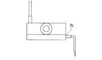
- the discharge port of the cell culture container is the mode shown in FIG. 12A, that is, the discharge port 7 b is arranged on the side surface of the cell culture container 7, and the amount of medium (height of the medium) in the cell culture container is constant.
- the mode in which the medium is discharged to the medium discharging unit 8 through the discharge port 7b is shown.
- the present invention is not limited to this.
- the modes shown in FIGS. 12A, 12B, 12C, and 12D are not limited to this.
- the modes shown in FIGS. 12A, 12B, 12C, and 12D are examples of the modes shown in FIGS. 12A, 12B, 12C, and 12D .
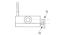
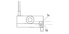
- the mode of FIG. 12B and FIG. 12C is a mode provided with the mechanism (discharge siphon mechanism 7d) similar to the siphon mechanism 6a of the culture medium supply means 6. That is, the discharge siphon mechanism 7d has a structure in which a flow path extends upward to a predetermined height in the direction of gravity from the discharge port 7b of the cell culture container, and then the flow path folds back and extends downward in the direction of gravity.
- the predetermined height at which the flow path extends upward in the direction of gravity is set to a position lower than the maximum height that the medium retained in the cell culture container can reach in the direction of gravity (hereinafter, this set height is referred to as the “turning point”). 7e ").
- the discharge siphon mechanism 7d functions as a medium intermittent discharge mechanism.
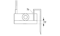
- the aspect of FIG. 12D is an aspect applicable to the system provided with the negative pressure supply means 71 for applying a negative pressure to the cell culture container 7.
- the tubular member of the medium discharge means 8 penetrates through the discharge port 7b of the cell culture container and extends from the bottom surface of the cell culture container to a predetermined height (7f).
- the predetermined height (7f) is set according to the type of cells to be cultured and the culture conditions.
- FIGS. 12A to 12D show a flask-like cell culture container, but a petri-like cell culture container or the like may be used as shown in FIGS. 13A to 13D.
- FIGS. 13A to 13D portions corresponding to FIGS. 12A to 12D are assigned the same numbers.
- a flask-like culture container is shown as a cell culture container to be used in the drawings, but a petri dish-like culture container or the like may be used as shown in FIGS. 13A to 13D.
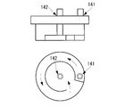
- a cell culture container having a threshold for forming a flow path may be used. If the supply port 141 and the discharge port 142 are installed at positions separated along the flow path using the container, the exchange efficiency of the medium is improved.
- FIG. 15A is an example corresponding to 1st Embodiment, other embodiment is also the same.
- a backup discharge port 4c may be installed in the temporary holding means 4. If the backup discharge port 4c is connected to the medium supply means 6 (for example, the branching means 6c) by a tubular member, the medium is removed when the medium in the temporary holding means 4 reaches the backup discharge port 4c without the siphon mechanism 6a functioning. It can be discharged to the medium supply means.
- the tubular member from the backup discharge port 4c may be connected to the medium discharge means 8 instead of the medium supply means 6, or may be connected to the medium storage means 3, for example.
- FIG. 15B is an example corresponding to the first embodiment, but the other embodiments are also the same.
- the medium storage means 3 is connected to the temporary holding means 4 via a tubular member (tube or the like), and the medium storage means 3 is installed at a position higher than the temporary holding means 4 in the direction of gravity. Therefore, although the culture medium in the culture medium storage means 3 has been shown to be supplied to the temporary holding means 4 via a tubular member (such as a tube) by gravity, for example, as shown in FIG. 16, the culture medium storage means and the temporary storage means A liquid feeding pump 5a such as a peristaltic pump may be installed as a supply speed adjusting means in a tubular member (tube or the like) connecting the medium, and the medium may be supplied from the medium storage means 3 to the temporary holding means 4.
- a liquid feeding pump 5a such as a peristaltic pump
- the culture medium holding means 3 does not necessarily have to be installed at a position above the temporary holding means 4 in the direction of gravity, and the degree of freedom of the installation place of the culture medium holding means 3 is increased.
- the liquid feed pump 5a such as a peristaltic pump may be remotely operated by the control means. The remote operation may be wired or wireless.
- FIG. 16 is an example corresponding to the first embodiment, but the other embodiments are also the same.
- the medium supply means 6 may include a supply speed adjusting means 5b.
- the installation location is preferably installed upstream of the branching means 6c.
- the configuration of the supply speed adjusting means 5b may be the same as that of the supply speed adjusting means 5 connected to the medium storage means 3 and the temporary holding means, which is installed in a tubular member (tube or the like).
- the control means may be remotely operated by wire or wirelessly.
- the waste liquid discharged from the discharge port of the culture container has been shown to be discharged through the waste liquid holding means.
- FIG. 18A is an example corresponding to 1st Embodiment, other embodiment is also the same.
- the suction port of the negative pressure supply means may be connected to each discharge port of the cell culture container.
- the medium temperature monitoring means for monitoring the medium temperature may be installed in the temporary holding means. At this time, information on the medium temperature monitored by the medium temperature monitoring means may be sent to the control unit remotely. As a result, it is possible to prevent a medium having a temperature not suitable for cell culture from being erroneously supplied.
- the medium exchange efficiency can be improved by making the amount of the medium retained in the cell culture container as small as possible. What is necessary is just to optimize the quantity of the culture medium hold
- a control unit installed outside the incubator can exchange information wirelessly or by wire with a temperature control unit, a pressure applying unit, a negative pressure supply unit, a liquid feed pump in each of the above embodiments, and remotely. You may be able to control them. As a result, the efficiency of remote work by the user can be increased.
- control unit may remotely operate the medium replacement based on a schedule (program) set in advance by the user.
- the temporary holding means may be installed outside the incubator.
- a temperature control means for maintaining the solution in the temporary holding means at a temperature suitable for cell culture (for example, 37 ° C.).
- the waste liquid holding unit may be installed outside the incubator.
- the waste liquid holding unit may be installed in the incubator.
- control unit of the present invention is a PC, and the PC can perform control executed by the control unit in each of the above embodiments. That is, the control unit is, for example, a PC having a CPU and a memory, and the function as the control unit is realized by the CPU executing a control program described in the memory.
- the medium temperature in the medium storage means 3 may be set to an appropriate temperature depending on the culture conditions. You may maintain at 37 degreeC with the temperature control means 2.
- FIG. Moreover, the culture medium storage means 3 may be installed in the incubator. In this case, the temperature control means 2 may be omitted if the culture medium temperature is maintained at 37 ° C.
- the medium storage means and the temporary medium holding means are means capable of holding a culture medium and other solutions (for example, a washing solution) and function as solution holding means.
- a culture medium and other solutions for example, a washing solution
- Each of the medium storage means and the temporary medium holding means functions as a solution holding means, and both means function as a solution holding means as a unit.
- medium storage means for holding a medium for culturing cells
- a temporary holding means connected to the medium storage means, a holding space for temporarily holding the medium supplied from the medium storage means, and a discharge port for discharging the medium
- Medium supply means connected to the discharge port of the temporary holding means and supplying the medium discharged from the temporary holding means to a cell culture container
- Medium discharge means for discharging the medium from the cell culture vessel
- a cell culture system comprising:
- the medium supply means can provide a cell culture system provided with a medium intermittent supply mechanism for supplying the medium discharged from the temporary holding means intermittently to the cell culture container at a predetermined cycle.
- medium storage means for holding a medium for culturing cells
- a temporary holding means connected to the medium storage means, a holding space for temporarily holding the medium supplied from the medium storage means, and a discharge port for discharging the medium
- Medium supply means connected to the discharge port of the temporary holding means and supplying the medium discharged from the temporary holding means to a cell culture container
- Medium discharge means for discharging the medium from the cell culture vessel
- a cell culture system comprising:
- the medium discharge means can provide a cell culture system provided with a medium intermittent discharge mechanism for discharging the medium inside the cell culture container to the outside intermittently at a predetermined cycle.
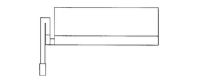
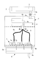
- the siphon mechanism 6a is installed outside the temporary holding unit 4.
- the tubular member forming the flow path of the siphon mechanism 6a extends upward from the discharge port 4b of the temporary holding means 4 toward the inside of the temporary holding means 4 to a predetermined height in the gravitational direction, and then turns back in the direction of gravity. It has a structure that extends downward.
- the end of the tubular member extending downward in the direction of gravity has a structure having an opening 6d in the vicinity of a gap from the bottom surface of the temporary holding means 4.
- the predetermined height at which the flow path of the siphon mechanism 6a reaches upward in the direction of gravity is set to a position lower than the maximum height at which the medium retained in the temporary holding means 4 can reach in the direction of gravity (hereinafter referred to as “the height of the medium”). This set height is referred to as “folding point 6b”).
- the siphon mechanism 6a of the present invention is a mechanism provided with a flow channel capable of intermittently supplying the medium from the temporary holding means 4 to the cell culture container according to the siphon principle.
- a cell culture container comprising a supply port for supplying a culture medium, a discharge port for discharging the culture medium, and a tubular member (discharge siphon mechanism) connected to the discharge port,
- the tubular member can provide a cell culture container that forms a flow path capable of intermittently discharging the medium in the cell culture container according to the principle of siphon.
- the cell culture vessel 7 illustrated in FIGS. 12B, 12C, 13B, and 13C can be provided. That is, the cell culture vessel 7 includes a supply port 7a for supplying a culture medium, a discharge port 7b for discharging the culture medium, and a tubular member (discharge siphon mechanism) connected to the discharge port 7b.
- the outlet 7b is disposed on the side of the container at a predetermined height from the bottom of the container, and the tubular member is positioned above the discharge port 7b in the direction of gravity and lower than the maximum height in the direction of gravity of the space in the container. It is the cell culture container 7 which forms the flow path to pass.
- the cell culture container 7 illustrated in FIGS. 20A and 20B can be provided. That is, the cell culture container 7 includes a supply port 7a for supplying a culture medium, a discharge port 7b for discharging the culture medium, and a tubular member (discharge siphon mechanism) connected to the discharge port 7b.
- the member is installed inside the cell culture container 7 and forms a flow path that passes through a position above the discharge port 7b in the direction of gravity and lower than the maximum height in the direction of gravity of the space in the container, and the discharge port of the tubular member
- the other end opposite to the end connected to 7b is the cell culture container 7 having an opening in the vicinity of the gap from the bottom surface of the cell culture container 7.
- the medium supply means 6 for supplying a medium to the inside of the cell culture container 7 can be connected to the supply port of the cell culture container 7 to form a cell culture system.
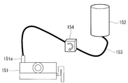
- a medium storage container 152 and a supply port 151a may be connected by a tubular member 153 such as a tube, and a liquid feed pump 154 may be installed on the tubular member 153.
- the supply port may be disposed on the upper surface of the cell culture vessel 7 and the medium may be dropped from the supply port onto the upper surface of the medium by the medium supply means 6.
- a medium is supplied into the cell culture container 7 by the medium supply means 6, and when the medium in the cell culture container 7 exceeds a predetermined amount, the discharge siphon mechanism 6a is set in accordance with the principle of siphon.
- the medium is discharged to a height, and the old medium and the new medium can be intermittently replaced.
- FIG. 22A An example of the cell culture container in this embodiment is shown in FIG. 22A.
- a culture medium and cells are accommodated in the cell culture bag 162 made of a porous membrane.
- the cell culture bag 162 is stored in the dialysis container 161 in a state immersed in a solution such as dialysis solution.
- the dialysis container 161 includes a supply port 161a for supplying a solution to the inside and a discharge port 161b for discharging the solution to the outside.
- the dialysis container 161 and the cell culture bag 162 function as the cell culture container in each of the above embodiments and modifications thereof.
- FIG. 22B Another example of the cell culture container is shown in FIG. 22B.
- a culture medium and cells are stored in the culture container 164.
- a solution such as dialysate is stored inside the dialysis bag 163 made of a porous membrane, and stored in the culture vessel 164 while immersed in a culture medium.
- the dialysis bag 163 includes a supply port 163a for supplying a solution to the inside and a discharge port 163b for discharging the solution to the outside.
- the dialysis bag 163 and the culture container 164 function as the cell culture container in each of the above embodiments and modifications thereof. According to this embodiment, the present invention can be applied not only to adherent cells but also to floating cells.
- Solution storage means for holding the solution
- Temporary holding means connected to the solution storage means, temporarily holding a solution supplied from the solution storage means, and a discharge port for discharging the solution
- a solution supply means connected to the discharge port of the temporary holding means and supplying the solution discharged from the temporary holding means to a cell culture container
- Discharging means for discharging the solution from the cell culture vessel
- a cell culture system comprising: The cell culture container is connected to the solution supply means at a position below the solution supply means in the direction of gravity, The solution supply means can provide a cell culture system provided with a flow path capable of intermittently supplying the solution from the temporary holding means to the cell culture container according to the principle of siphon.
- Temporary holding means having a solution storage means for holding the solution, a holding space for temporarily holding the solution supplied from the solution storage means, and a discharge port for discharging the solution, connected to the solution storage means
- a solution supply means connected to the discharge port of the temporary holding means and supplying the solution discharged from the temporary holding means to a cell culture container;
- Discharging means for discharging the solution from the cell culture vessel;
- a cell culture system comprising: The cell culture container is connected to the solution supply means at a position below the solution supply means in the direction of gravity, The solution supply means can provide a cell culture system including a supply gate that opens a flow path when a medium in the holding space reaches a predetermined amount.
Landscapes
- Health & Medical Sciences (AREA)
- Chemical & Material Sciences (AREA)
- Wood Science & Technology (AREA)
- Life Sciences & Earth Sciences (AREA)
- Engineering & Computer Science (AREA)
- Bioinformatics & Cheminformatics (AREA)
- Organic Chemistry (AREA)
- Zoology (AREA)
- Biomedical Technology (AREA)
- Sustainable Development (AREA)
- Microbiology (AREA)
- Biochemistry (AREA)
- General Engineering & Computer Science (AREA)
- General Health & Medical Sciences (AREA)
- Genetics & Genomics (AREA)
- Biotechnology (AREA)
- Clinical Laboratory Science (AREA)
- Analytical Chemistry (AREA)
- Apparatus Associated With Microorganisms And Enzymes (AREA)
Abstract
L'invention vise à permettre l'échange simple et automatique de milieu dans un récipient de culture cellulaire installé dans un incubateur. Le système de culture cellulaire de l'invention est pourvu : d'un moyen de stockage de milieu (3) pour stocker un milieu de culture cellulaire ; d'un moyen de maintien temporaire (4) relié au moyen de stockage de milieu (3) et pourvu d'un espace de maintien destiné à maintenir temporairement le milieu fourni à partir du moyen de stockage de milieu (3) et d'une sortie pour évacuer le milieu ; d'un moyen d'alimentation en milieu (6) relié à la sortie du moyen de maintien temporaire (4), le moyen d'alimentation en milieu (6) fournissant le milieu évacué à partir du moyen de maintien temporaire (4) à un récipient de culture cellulaire (7) ; et d'un moyen d'évacuation (8) pour évacuer le milieu à partir du récipient de culture cellulaire (4). Le moyen d'alimentation en milieu est pourvu d'un mécanisme d'alimentation intermittente en milieu permettant de fournir de manière intermittente le milieu évacué à partir du moyen de maintien temporaire au récipient de culture cellulaire (4) selon un cycle prescrit.
Priority Applications (4)
| Application Number | Priority Date | Filing Date | Title |
|---|---|---|---|
| EP15857361.8A EP3216857A4 (fr) | 2014-11-06 | 2015-11-05 | Système de culture cellulaire et récipient de culture cellulaire |
| CN201580059368.8A CN107109336A (zh) | 2014-11-06 | 2015-11-05 | 细胞培养系统以及细胞培养容器 |
| JP2016557801A JPWO2016072460A1 (ja) | 2014-11-06 | 2015-11-05 | 細胞培養システムおよび細胞培養容器 |
| US15/495,435 US20170226465A1 (en) | 2014-11-06 | 2017-04-24 | Cell culture system and cell culture vessel |
Applications Claiming Priority (2)
| Application Number | Priority Date | Filing Date | Title |
|---|---|---|---|
| JP2014225781 | 2014-11-06 | ||
| JP2014-225781 | 2014-11-06 |
Related Child Applications (1)
| Application Number | Title | Priority Date | Filing Date |
|---|---|---|---|
| US15/495,435 Continuation US20170226465A1 (en) | 2014-11-06 | 2017-04-24 | Cell culture system and cell culture vessel |
Publications (1)
| Publication Number | Publication Date |
|---|---|
| WO2016072460A1 true WO2016072460A1 (fr) | 2016-05-12 |
Family
ID=55909184
Family Applications (1)
| Application Number | Title | Priority Date | Filing Date |
|---|---|---|---|
| PCT/JP2015/081200 Ceased WO2016072460A1 (fr) | 2014-11-06 | 2015-11-05 | Système de culture cellulaire et récipient de culture cellulaire |
Country Status (5)
| Country | Link |
|---|---|
| US (1) | US20170226465A1 (fr) |
| EP (1) | EP3216857A4 (fr) |
| JP (1) | JPWO2016072460A1 (fr) |
| CN (1) | CN107109336A (fr) |
| WO (1) | WO2016072460A1 (fr) |
Cited By (4)
| Publication number | Priority date | Publication date | Assignee | Title |
|---|---|---|---|---|
| WO2016157865A1 (fr) * | 2015-03-27 | 2016-10-06 | 川崎重工業株式会社 | Dispositif de pipettage de solution de médicament, système de transport de solution de médicament, et procédé de transport de solution de médicament |
| WO2018186426A1 (fr) * | 2017-04-07 | 2018-10-11 | オリンパス株式会社 | Dispositif d'échange de milieu de culture et système de culture |
| KR102019437B1 (ko) * | 2018-05-21 | 2019-09-09 | 주식회사 다나그린 | 세포 배양액 자동공급시스템 |
| WO2024150585A1 (fr) * | 2023-01-12 | 2024-07-18 | パナソニックIpマネジメント株式会社 | Récipient de culture et dispositif de culture cellulaire |
Families Citing this family (7)
| Publication number | Priority date | Publication date | Assignee | Title |
|---|---|---|---|---|
| JP7451877B2 (ja) * | 2019-04-27 | 2024-03-19 | 東洋製罐グループホールディングス株式会社 | 細胞培養システム |
| CN112574883B (zh) * | 2020-12-15 | 2022-10-14 | 山东省农业科学院畜牧兽医研究所 | 一种动物肌肉细胞培养用装置 |
| EP4303295A4 (fr) * | 2021-03-26 | 2024-11-06 | TERUMO Kabushiki Kaisha | Système de culture cellulaire |
| JP7720162B2 (ja) * | 2021-04-27 | 2025-08-07 | 株式会社日立製作所 | 細胞培養システム |
| CN113353307B (zh) * | 2021-06-03 | 2022-08-02 | 北京君立康生物科技有限公司 | 物料分装设备 |
| US12606791B2 (en) | 2023-01-19 | 2026-04-21 | Drsignal Biotechnology Co., Ltd. | Gravitational liquid-splitting device, cell passaging device with the same, and cell passaging method |
| EP4410950B1 (fr) * | 2023-02-02 | 2025-05-28 | Drsignal Biotechnology Co., Ltd | Dispositif gravitationnel de séparation de liquides, dispositif de passage de cellules doté de celui-ci et procédé de passage de cellules |
Citations (3)
| Publication number | Priority date | Publication date | Assignee | Title |
|---|---|---|---|---|
| JPH06165624A (ja) * | 1992-12-02 | 1994-06-14 | Iwate Pref Gov | 植物体の培養方法及びバイオリアクタ |
| JP2002159241A (ja) * | 2000-11-27 | 2002-06-04 | Central Res Inst Of Electric Power Ind | 魚介類飼育装置 |
| JP2004089137A (ja) * | 2002-09-03 | 2004-03-25 | Olympus Corp | 培養装置および培地交換方法 |
Family Cites Families (6)
| Publication number | Priority date | Publication date | Assignee | Title |
|---|---|---|---|---|
| GB2314343B (en) * | 1996-06-18 | 2000-08-23 | Liau Ming Yi | Method and apparatus for cultivating anchorage dependent monolayer cells |
| CN2582624Y (zh) * | 2002-09-08 | 2003-10-29 | 高建国 | 一次性自动控制输液器 |
| CN2827400Y (zh) * | 2005-09-14 | 2006-10-18 | 王佰河 | 自动报警输液器 |
| CN101457205B (zh) * | 2009-01-08 | 2011-11-16 | 上海交通大学 | 虹吸式间歇喷雾生物反应器 |
| CN102998198B (zh) * | 2012-12-04 | 2014-10-15 | 上海交通大学 | 测定植物离体根比生长速率的装置和方法 |
| CN203820795U (zh) * | 2014-05-05 | 2014-09-10 | 王贺民 | 虹吸式高密度细胞培养瓶 |
-
2015
- 2015-11-05 EP EP15857361.8A patent/EP3216857A4/fr not_active Withdrawn
- 2015-11-05 WO PCT/JP2015/081200 patent/WO2016072460A1/fr not_active Ceased
- 2015-11-05 JP JP2016557801A patent/JPWO2016072460A1/ja active Pending
- 2015-11-05 CN CN201580059368.8A patent/CN107109336A/zh active Pending
-
2017
- 2017-04-24 US US15/495,435 patent/US20170226465A1/en not_active Abandoned
Patent Citations (3)
| Publication number | Priority date | Publication date | Assignee | Title |
|---|---|---|---|---|
| JPH06165624A (ja) * | 1992-12-02 | 1994-06-14 | Iwate Pref Gov | 植物体の培養方法及びバイオリアクタ |
| JP2002159241A (ja) * | 2000-11-27 | 2002-06-04 | Central Res Inst Of Electric Power Ind | 魚介類飼育装置 |
| JP2004089137A (ja) * | 2002-09-03 | 2004-03-25 | Olympus Corp | 培養装置および培地交換方法 |
Non-Patent Citations (1)
| Title |
|---|
| See also references of EP3216857A4 * |
Cited By (10)
| Publication number | Priority date | Publication date | Assignee | Title |
|---|---|---|---|---|
| WO2016157865A1 (fr) * | 2015-03-27 | 2016-10-06 | 川崎重工業株式会社 | Dispositif de pipettage de solution de médicament, système de transport de solution de médicament, et procédé de transport de solution de médicament |
| WO2018186426A1 (fr) * | 2017-04-07 | 2018-10-11 | オリンパス株式会社 | Dispositif d'échange de milieu de culture et système de culture |
| KR102019437B1 (ko) * | 2018-05-21 | 2019-09-09 | 주식회사 다나그린 | 세포 배양액 자동공급시스템 |
| WO2019225893A1 (fr) * | 2018-05-21 | 2019-11-28 | 주식회사 다나그린 | Incubateur de cellules automatisé 3d |
| JP2021524284A (ja) * | 2018-05-21 | 2021-09-13 | ダナグリーン カンパニー リミテッドDanagreen Co., Ltd. | 3次元自動細胞培養装置 |
| JP7263508B2 (ja) | 2018-05-21 | 2023-04-24 | ダナグリーン カンパニー リミテッド | 3次元自動細胞培養装置 |
| JP2023089137A (ja) * | 2018-05-21 | 2023-06-27 | ダナグリーン カンパニー リミテッド | 3次元自動細胞培養装置 |
| US11884908B2 (en) | 2018-05-21 | 2024-01-30 | Danagreen Co., Ltd. | 3D cell automated incubator |
| JP7573901B2 (ja) | 2018-05-21 | 2024-10-28 | ダナグリーン カンパニー リミテッド | 3次元自動細胞培養装置 |
| WO2024150585A1 (fr) * | 2023-01-12 | 2024-07-18 | パナソニックIpマネジメント株式会社 | Récipient de culture et dispositif de culture cellulaire |
Also Published As
| Publication number | Publication date |
|---|---|
| EP3216857A4 (fr) | 2018-08-01 |
| EP3216857A1 (fr) | 2017-09-13 |
| US20170226465A1 (en) | 2017-08-10 |
| JPWO2016072460A1 (ja) | 2017-08-31 |
| CN107109336A (zh) | 2017-08-29 |
Similar Documents
| Publication | Publication Date | Title |
|---|---|---|
| WO2016072460A1 (fr) | Système de culture cellulaire et récipient de culture cellulaire | |
| JP6675309B2 (ja) | 細胞培養システム | |
| US20150017711A1 (en) | Cell culture systems | |
| US11441114B2 (en) | Liquid feed device, and cell culture device and method using same | |
| WO2016027800A1 (fr) | Sac, dispositif et réceptacle pour la culture cellulaire | |
| US20160194591A1 (en) | Bioreactor with addition tube | |
| JP4732187B2 (ja) | 自動培養装置 | |
| JP2012508675A5 (fr) | ||
| JP2015084686A (ja) | 細胞培養用ジグおよび自動培地交換システム | |
| JP2017023131A (ja) | 細胞培養装置 | |
| US20170275579A1 (en) | Cell culture apparatus and cell culture bag | |
| JPWO2015111348A1 (ja) | 細胞培養装置 | |
| TWI756886B (zh) | 細胞培養裝置 | |
| JP6294485B2 (ja) | 送液装置、及び細胞培養装置 | |
| KR102350723B1 (ko) | 자동 배지 교체 시스템 | |
| JPWO2017122658A1 (ja) | 細胞培養容器および容器ホルダ | |
| JP6858653B2 (ja) | 送液装置およびそれを用いた細胞培養装置 | |
| CN102670412A (zh) | 微量补液装置 | |
| AU2014205437B2 (en) | Multiple channel single spike for a liquid dispensing system | |
| JP7237225B1 (ja) | 充填針モジュール及び充填装置 | |
| JP6604467B2 (ja) | 細胞懸濁液の供給装置 | |
| JP2008292186A (ja) | バッチプラントにおける精密計量システム | |
| JPWO2017154124A1 (ja) | 培養容器、培養装置、培養方法 | |
| JP2015099134A (ja) | 液体計量ユニットおよび液体供給装置 |
Legal Events
| Date | Code | Title | Description |
|---|---|---|---|
| 121 | Ep: the epo has been informed by wipo that ep was designated in this application |
Ref document number: 15857361 Country of ref document: EP Kind code of ref document: A1 |
|
| ENP | Entry into the national phase |
Ref document number: 2016557801 Country of ref document: JP Kind code of ref document: A |
|
| NENP | Non-entry into the national phase |
Ref country code: DE |
|
| REEP | Request for entry into the european phase |
Ref document number: 2015857361 Country of ref document: EP |