WO2016076108A1 - Batterie secondaire prismatique - Google Patents
Batterie secondaire prismatique Download PDFInfo
- Publication number
- WO2016076108A1 WO2016076108A1 PCT/JP2015/080308 JP2015080308W WO2016076108A1 WO 2016076108 A1 WO2016076108 A1 WO 2016076108A1 JP 2015080308 W JP2015080308 W JP 2015080308W WO 2016076108 A1 WO2016076108 A1 WO 2016076108A1
- Authority
- WO
- WIPO (PCT)
- Prior art keywords
- current collector
- electrode current
- negative electrode
- positive electrode
- collector plate
- Prior art date
- Legal status (The legal status is an assumption and is not a legal conclusion. Google has not performed a legal analysis and makes no representation as to the accuracy of the status listed.)
- Ceased
Links
Images







Classifications
-
- H—ELECTRICITY
- H01—ELECTRIC ELEMENTS
- H01M—PROCESSES OR MEANS, e.g. BATTERIES, FOR THE DIRECT CONVERSION OF CHEMICAL ENERGY INTO ELECTRICAL ENERGY
- H01M50/00—Constructional details or processes of manufacture of the non-active parts of electrochemical cells other than fuel cells, e.g. hybrid cells
- H01M50/50—Current conducting connections for cells or batteries
- H01M50/531—Electrode connections inside a battery casing
-
- H—ELECTRICITY
- H01—ELECTRIC ELEMENTS
- H01M—PROCESSES OR MEANS, e.g. BATTERIES, FOR THE DIRECT CONVERSION OF CHEMICAL ENERGY INTO ELECTRICAL ENERGY
- H01M10/00—Secondary cells; Manufacture thereof
- H01M10/05—Accumulators with non-aqueous electrolyte
- H01M10/058—Construction or manufacture
- H01M10/0587—Construction or manufacture of accumulators having only wound construction elements, i.e. wound positive electrodes, wound negative electrodes and wound separators
-
- H—ELECTRICITY
- H01—ELECTRIC ELEMENTS
- H01M—PROCESSES OR MEANS, e.g. BATTERIES, FOR THE DIRECT CONVERSION OF CHEMICAL ENERGY INTO ELECTRICAL ENERGY
- H01M50/00—Constructional details or processes of manufacture of the non-active parts of electrochemical cells other than fuel cells, e.g. hybrid cells
- H01M50/10—Primary casings; Jackets or wrappings
- H01M50/102—Primary casings; Jackets or wrappings characterised by their shape or physical structure
- H01M50/103—Primary casings; Jackets or wrappings characterised by their shape or physical structure prismatic or rectangular
-
- H—ELECTRICITY
- H01—ELECTRIC ELEMENTS
- H01M—PROCESSES OR MEANS, e.g. BATTERIES, FOR THE DIRECT CONVERSION OF CHEMICAL ENERGY INTO ELECTRICAL ENERGY
- H01M50/00—Constructional details or processes of manufacture of the non-active parts of electrochemical cells other than fuel cells, e.g. hybrid cells
- H01M50/10—Primary casings; Jackets or wrappings
- H01M50/147—Lids or covers
-
- H—ELECTRICITY
- H01—ELECTRIC ELEMENTS
- H01M—PROCESSES OR MEANS, e.g. BATTERIES, FOR THE DIRECT CONVERSION OF CHEMICAL ENERGY INTO ELECTRICAL ENERGY
- H01M50/00—Constructional details or processes of manufacture of the non-active parts of electrochemical cells other than fuel cells, e.g. hybrid cells
- H01M50/10—Primary casings; Jackets or wrappings
- H01M50/172—Arrangements of electric connectors penetrating the casing
- H01M50/174—Arrangements of electric connectors penetrating the casing adapted for the shape of the cells
- H01M50/176—Arrangements of electric connectors penetrating the casing adapted for the shape of the cells for prismatic or rectangular cells
-
- Y—GENERAL TAGGING OF NEW TECHNOLOGICAL DEVELOPMENTS; GENERAL TAGGING OF CROSS-SECTIONAL TECHNOLOGIES SPANNING OVER SEVERAL SECTIONS OF THE IPC; TECHNICAL SUBJECTS COVERED BY FORMER USPC CROSS-REFERENCE ART COLLECTIONS [XRACs] AND DIGESTS
- Y02—TECHNOLOGIES OR APPLICATIONS FOR MITIGATION OR ADAPTATION AGAINST CLIMATE CHANGE
- Y02E—REDUCTION OF GREENHOUSE GAS [GHG] EMISSIONS, RELATED TO ENERGY GENERATION, TRANSMISSION OR DISTRIBUTION
- Y02E60/00—Enabling technologies; Technologies with a potential or indirect contribution to GHG emissions mitigation
- Y02E60/10—Energy storage using batteries
-
- Y—GENERAL TAGGING OF NEW TECHNOLOGICAL DEVELOPMENTS; GENERAL TAGGING OF CROSS-SECTIONAL TECHNOLOGIES SPANNING OVER SEVERAL SECTIONS OF THE IPC; TECHNICAL SUBJECTS COVERED BY FORMER USPC CROSS-REFERENCE ART COLLECTIONS [XRACs] AND DIGESTS
- Y02—TECHNOLOGIES OR APPLICATIONS FOR MITIGATION OR ADAPTATION AGAINST CLIMATE CHANGE
- Y02P—CLIMATE CHANGE MITIGATION TECHNOLOGIES IN THE PRODUCTION OR PROCESSING OF GOODS
- Y02P70/00—Climate change mitigation technologies in the production process for final industrial or consumer products
- Y02P70/50—Manufacturing or production processes characterised by the final manufactured product
Definitions
- the present invention relates to a prismatic secondary battery having a group of electrodes formed in a flat shape by winding a strip-like positive electrode and a negative electrode with a separator interposed therebetween.
- Patent Document 1 as an electrode group of a nonaqueous electrolyte battery, a plurality of positive current collecting tabs and a plurality of negative current collecting tabs are aligned from the end surface on one side in the winding axis direction in a flat shape. An electrode group with a protruding configuration is shown. This electrode group is fixed by laser welding to a cap body in which positive and negative electrode current collecting tabs are provided with current terminals for external extraction.
- the nonaqueous electrolyte battery was formed by inserting an electrode group with a cap body into an outer can, sealing the cap body to the outer can by laser welding, and injecting a nonaqueous electrolyte from an inlet provided in the cap body. It is produced by sealing the injection port later with a sealing plug.
- Patent Document 1 When the electrode group shown in Patent Document 1 is applied to a relatively large one used for an electric vehicle EV or a hybrid vehicle HEV, for example, vibration or impact is applied due to traveling or the like, and the current terminal for external extraction is applied. There is a concern about the influence on the strength of the joint between the current collector tab and the current collector plate to be fixed.
- the present invention has been made in view of the above points, and an object of the present invention is to obtain a prismatic secondary battery with high reliability against impact and vibration.
- the prismatic secondary battery of the present invention that solves the above problems includes a flat wound group in which a positive electrode and a negative electrode are wound with a separator interposed therebetween, a battery can that accommodates the wound group, and the battery
- a prismatic secondary battery having a battery lid for sealing a can, and a positive electrode current collector plate and a negative electrode current collector plate provided on the battery lid, wherein the winding group is arranged on one side in the winding axis direction.
- a plurality of positive electrode current collecting tabs and a plurality of negative electrode current collecting tabs are separately arranged in a pair of diagonal areas set in advance on the end face and joined to the positive electrode current collecting plate and the negative electrode current collecting plate, respectively. It is supported by the battery lid.
- FIG. 1 is an external perspective view of a prismatic secondary battery in Example 1.
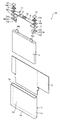
- FIG. 1 is an exploded perspective view of a prismatic secondary battery in Example 1.
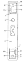
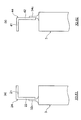
- FIG. FIG. 6 is a cross-sectional view taken along line X1-X1 and line X2-X2 in FIG. The figure explaining the joining state of the winding group and current collector plate in Example 2.
- FIG. FIG. 8 is a cross-sectional view taken along line X1-X1 and line X2-X2 in FIG. The figure explaining the joining state of the winding group and current collector plate in Example 3.
- FIG. 10 is an arrow view of the X1-X1 line cross section and the X2-X2 line cross section of FIG. 9.
- FIG. 6 is an exploded perspective view of a prismatic secondary battery in Example 4. The figure explaining the joining state of the winding group and current collection board in Example 4.
- FIG. 6 is an exploded perspective view of a prismatic secondary battery in Example 4. The figure explaining the joining state of the winding group and current collection board in Example 4.
- this embodiment is not limited to the following contents and is disclosed in the present specification. Various changes and modifications can be made by those skilled in the art within the scope of the technical idea to be made.
- components having the same function are denoted by the same reference numerals, and repeated description thereof may be omitted.
- the prismatic secondary battery is a lithium ion secondary battery
- the present invention is not limited to a lithium ion secondary battery, and other prismatic secondary batteries. It is applicable to.
- FIG. 1 is an external perspective view of the prismatic secondary battery according to the first embodiment
- FIG. 2 is an exploded perspective view of the prismatic secondary battery according to the first embodiment.
- the prismatic secondary battery 100 has a structure in which a flat wound group 3 is enclosed in a battery container together with an electrolyte solution (not shown).
- the battery container includes a battery can 1 and a battery lid 6.
- the battery can 1 has a pair of opposed wide side surfaces 1b having a relatively large area, a pair of opposed narrow side surfaces 1c and a bottom surface 1d having a relatively small area, and the upper portion is opened by an opening 1a. ing.
- the wound group 3 is accommodated in the battery can 1, and the opening 1 a of the battery can 1 is sealed by the battery lid 6.
- the battery lid 6 has a substantially rectangular flat plate shape, and is welded so as to close the opening 1 a of the battery can 1 to seal the battery can 1.
- an electrolytic solution is injected into the battery can 1 from a liquid injection port 9 that opens in the battery lid 6, and then a liquid injection stopper 11 is joined to the battery lid 6 by laser welding. It is sealed by sealing.
- the battery lid 6 is provided with a positive external terminal 14 and a negative external terminal 12.
- the positive external terminal 14 and the negative external terminal 12 are provided with a gasket 5 and an insulating plate 7 therebetween in order to electrically insulate from the battery lid 6.
- the battery cover 6 is integrally provided with a gas discharge valve 10, and when the pressure in the battery container rises, the gas discharge valve 10 opens to discharge gas from the inside, and the pressure in the battery container is reduced. Thereby, the safety of the prismatic secondary battery 100 is ensured.
- a wound group 3 is accommodated in the battery can 1 via an insulating protective film 2.
- the insulating protective film 2 is folded so as to wrap the wound group 3 and is inserted into the battery can 1 together with the wound group 3.
- the wound group 3 Since the wound group 3 is wound in a flat shape, the wound group 3 has a pair of opposed curved portions having a semicircular cross section and a flat portion formed continuously between the pair of curved portions. Yes.
- a plurality of positive electrode current collecting tabs 34 c made of a positive electrode metal foil exposed portion of the positive electrode 34 and a plurality of negative electrode metal foil exposed portions of the negative electrode 32 are formed on one end surface of the winding group 3 in the winding axis direction.
- a negative electrode current collecting tab 32c is provided so as to protrude.
- the plurality of positive electrode current collecting tabs 34c and the plurality of negative electrode current collecting tabs 32c are separately arranged in a pair of diagonal regions on the end surface on one side in the winding axis direction of the winding group. Each of them forms a tab group by projecting together.
- the tab group of the positive electrode current collecting tab 34c and the tab group of the negative electrode current collecting tab 32c are joined to the positive electrode current collecting plate 44 and the negative electrode current collecting plate 24 of the battery cover 6, respectively. It is supported by.
- the winding group 3 is inserted into the battery can 1 from one side in the winding axis direction so that the winding axis direction is along the longitudinal width direction (height direction) of the battery can 1, and the positive electrode current collecting tab 34 c and the negative electrode current collector 34 are arranged.
- Winding axis direction in which the other end surface of the winding axis direction where the electric tab 32c does not protrude is arranged to face the bottom surface 1d of the battery can 1, and the positive current collecting tab 34c and the negative current collecting tab 32c protrude.
- One end face is disposed on the opening 1 a side of the battery can 1.
- the winding group 3 in the present embodiment has a configuration in which both the positive electrode current collecting tab 34c of the positive electrode 34 and the negative electrode current collecting tab 32c of the negative electrode 32 are arranged on one side in the winding axis direction.
- the battery can When the size of 1 is the same, the width of the electrode mixture layer can be made wider. That is, the dead space in the battery can 1 can be reduced, the volume occupied by the electrode mixture layer in the battery can 1 can be increased, and the capacity of the battery can be increased.
- the tab group of the positive electrode current collecting tab 34 c is bundled so as to overlap each other in the thickness direction of the winding group 3, and is joined to the positive electrode current collector plate (current collector terminal) 44.
- the positive electrode external terminal 14 provided on the lid 6 is electrically connected.
- the tab group of the negative electrode current collecting tab 32c is bundled together in the thickness direction of the wound group 3, and joined to the negative electrode current collector plate (current collector terminal) 24. And is electrically connected to the negative external terminal 12 provided on the battery lid 6. Thereby, the wound group 3 is supported by the battery lid 6 in the battery can 1.
- Examples of the material for forming the positive electrode external terminal 14 and the positive electrode current collector plate 44 include an aluminum alloy, and examples of the material for forming the negative electrode external terminal 12 and the negative electrode current collector plate 24 include a copper alloy.
- Examples of the material for forming the insulating plate 7 and the gasket 5 include resin materials having insulating properties such as polybutylene terephthalate, polyphenylene sulfide, and perfluoroalkoxy fluororesin.
- the battery lid 6 has an injection port 9 for injecting an electrolyte into the battery container.
- the injection port 9 is sealed by an injection plug 11 after the electrolyte is injected into the battery container. Stopped.
- a non-aqueous electrolytic solution in which a lithium salt such as lithium hexafluorophosphate (LiPF 6 ) is dissolved in a carbonate ester-based organic solvent such as ethylene carbonate is used. Can be applied.
- the positive external terminal 14 and the negative external terminal 12 have a weld joint that is welded to a bus bar or the like.
- the weld joint has a rectangular parallelepiped block shape protruding upward from the battery lid 6, and has a configuration in which the lower surface faces the surface of the battery lid 6 and the upper surface is parallel to the battery lid 6 at a predetermined height position. Have.
- the positive electrode connection portion 14a and the negative electrode connection portion 12a have cylindrical shapes that protrude from the lower surfaces of the positive electrode external terminal 14 and the negative electrode external terminal 12, respectively, and have tips that can be inserted into the positive electrode side through hole 6B and the negative electrode side through hole 6A. Have.
- the positive electrode connection part 14a and the negative electrode connection part 12a penetrate the battery lid 6 and protrude to the inner side of the battery can 1 from the current collector plate bases 41 and 21 of the positive electrode current collector plate 44 and the negative electrode current collector plate 24, The tip is caulked, and the positive electrode external terminal 14, the negative electrode external terminal 12, the positive electrode current collector plate 44, and the negative electrode current collector plate 24 are integrally fixed to the battery lid 6.
- a gasket 5 is interposed between the positive electrode external terminal 14 and the negative electrode external terminal 12 and the battery lid 6, and an insulating plate 7 is interposed between the positive electrode current collector plate 44, the negative electrode current collector plate 24 and the battery lid 6. Intervened.
- the positive electrode current collector plate 44 and the negative electrode current collector plate 24 are rectangular plate-shaped current collector plate base portions 41 and 21 disposed opposite to the lower surface of the battery lid 6, and side ends of the current collector plate base portions 41 and 21, respectively. It is bent, protrudes toward the bottom surface 1d side along the wide side surface 1b of the battery can 1, and faces and overlaps the tab group of the positive electrode current collecting tab 34c of the wound group 3 and the tab group of the negative electrode current collecting tab 32c. In this state, there are joined end portions 42 and 22 joined to these tab groups. Opening holes 43 and 23 through which the positive electrode connecting portion 14a and the negative electrode connecting portion 12a are inserted are formed in the current collector plate base portions 41 and 21, respectively.
- the insulating protective film 2 is wound around the winding group 3 with the direction along the flat portion of the winding group 3 and the direction perpendicular to the winding axis direction of the winding group 3 as the central axis direction.
- the insulating protective film 2 is made of a single sheet or a plurality of film members made of synthetic resin such as PP (polypropylene), for example, and is a direction parallel to the flat surface of the wound group 3 and perpendicular to the winding axis direction. Can be wrapped around the winding group 3.
- FIG. 3 is an exploded perspective view showing a state in which a part of the wound electrode group is developed.
- the winding group 3 is configured by winding the negative electrode 32 and the positive electrode 34 in a flat shape with the separators 33 and 35 interposed therebetween.
- the outermost electrode is the negative electrode 32, and the separators 33 and 35 are wound outside thereof.
- the separators 33 and 35 have a role of insulating between the positive electrode 34 and the negative electrode 32.
- the positive electrode 34 has a positive electrode mixture layer 34b in which a positive electrode active material mixture is applied to both surfaces of a positive electrode metal foil that is a positive electrode current collector, and a positive electrode at the long side end on one side in the width direction of the positive electrode metal foil.
- a positive electrode metal foil exposed portion to which no active material mixture is applied is provided, and a plurality of positive electrode current collecting tabs 34c are formed in the positive electrode metal foil exposed portion.
- the negative electrode 32 has a negative electrode mixture layer 32b in which a negative electrode active material mixture is applied on both sides of a negative electrode metal foil that is a negative electrode current collector, and a negative electrode at the long side end on one side in the width direction of the negative electrode metal foil.
- a negative electrode metal foil exposed portion to which no active material mixture is applied is provided, and a plurality of negative electrode current collecting tabs 32c are formed in the negative electrode metal foil exposed portion.
- the negative electrode mixture layer 32b of the negative electrode 32 is larger in the winding width direction than the positive electrode mixture layer 34b of the positive electrode 34.
- the positive electrode mixture layer is It is configured to be sandwiched between the negative electrode mixture layers.
- the positive electrode 34 and the negative electrode 32 are wound on each other so that the exposed portions of the metal foil are arranged on one side in the winding axis direction.
- the plurality of positive electrode current collecting tabs 34 c and the plurality of negative electrode current collecting tabs 32 c are provided at predetermined intervals in the longitudinal direction of the positive electrode 34 and the negative electrode 32, and are wound around the positive electrode 34 and the negative electrode 32. In this state, each of the flat portions of the winding group 3 is formed at a position overlapping in the thickness direction of the winding group 3.
- the tab group of the positive electrode current collecting tab 34c and the tab group of the negative electrode current collector tab 32c protrude from the separators 33 and 35 to one side in the winding axis direction, that is, in a diagonal position.
- the relative positions in the longitudinal direction of the positive electrode 34 and the negative electrode 32 are determined and wound so as to be divided into a pair of preset diagonal regions on one end face in the axial direction. Specifically, the relative positions of the positive electrode 34 and the negative electrode 32 are adjusted so that the positive electrode current collecting tab 34c of the positive electrode 34 is disposed at an intermediate position between the negative electrode current collecting tabs 32c adjacent to each other. Then they are wound on top of each other.
- region is a position where the winding group 3 was separated into one side and the other side in the thickness direction of the winding group 3 on the end surface on one side in the winding axis direction. Two regions which are biased toward one bending portion side and the other bending portion side are shown.
- the tab group of the positive electrode current collecting tab 34c and the tab group of the negative electrode current collecting tab 32c are bundled in the thickness direction of the winding group 3 at the flat portion of the winding group 3, respectively.
- the negative electrode current collector plate 24 is joined to the joining end 22 by ultrasonic welding or the like. Thereby, the wound group 3 is supported in a state of being suspended from the battery lid 6 by the positive electrode current collector plate 44 and the negative electrode current collector plate 24.
- the separators 33 and 35 are wider in the winding width direction than the portion where the negative electrode mixture layer is applied, but are wound at positions where the metal foil surface at the end is exposed at the positive foil exposed portion and the negative foil exposed portion. Therefore, it does not hinder bundle welding.
- negative electrode 32 10 parts by weight of polyvinylidene fluoride (hereinafter referred to as PVDF) is added as a binder to 100 parts by weight of amorphous carbon powder as a negative electrode active material, and N as a dispersion solvent.
- NMP kneading methylpyrrolidone
- amorphous carbon is used as the negative electrode active material, but the present invention is not limited to this.
- Natural graphite capable of inserting and removing lithium ions and various artificial graphite materials Carbonaceous materials such as coke, compounds such as Si and Sn (for example, SiO, TiSi 2 etc.), or composite materials thereof may be used. It is not limited.
- the positive electrode 34 10 parts by weight of flaky graphite as a conductive material and 10 parts by weight of PVDF as a binder are added to 100 parts by weight of lithium manganate (chemical formula LiMn 2 O 4 ) as a positive electrode active material.
- a positive electrode mixture was prepared by adding and kneading NMP as a dispersion solvent. The positive electrode mixture was applied to both surfaces of an aluminum foil (positive metal foil) having a thickness of 20 ⁇ m leaving a welded portion (positive electrode uncoated portion). Thereafter, a positive electrode 34 having a thickness of 90 ⁇ m in the thickness of the positive electrode active material coating portion not including an aluminum foil was obtained through drying, pressing, and cutting processes.
- lithium manganate is used as the positive electrode active material
- other lithium manganate having a spinel crystal structure or a lithium manganese composite oxide or layered in which a part is substituted or doped with a metal element A lithium cobalt oxide or lithium titanate having a crystal structure, or a lithium-metal composite oxide obtained by substituting or doping a part thereof with a metal element may be used.
- PVDF polytetrafluoroethylene
- polyethylene polyethylene
- polystyrene polybutadiene
- butyl rubber nitrile rubber
- styrene Use polymers such as butadiene rubber, polysulfide rubber, nitrocellulose, cyanoethyl cellulose, various latexes, acrylonitrile, vinyl fluoride, vinylidene fluoride, propylene fluoride, chloroprene fluoride, acrylic resins, and mixtures thereof.
- PTFE polytetrafluoroethylene
- polystyrene polystyrene
- polybutadiene butyl rubber
- nitrile rubber styrene
- styrene Use polymers such as butadiene rubber, polysulfide rubber, nitrocellulose, cyanoethyl cellulose, various latexes, acrylonitrile, vinyl fluoride, vinylidene fluoride, propylene fluoride, chlor
- the wound group 3 may be either a type having an axis or a type having no axis, but in this embodiment, a type having an axis is used. Used.
- the shaft core for example, a structure in which a resin sheet having higher bending rigidity than any of the positive electrode metal foil, the negative electrode metal foil, and the separators 33 and 35 is wound can be used.
- FIG. 4 is a view of the battery lid as seen from the bottom side of the battery can
- FIG. 5 is a view for explaining the joining state of the winding group and the current collector plate in Example 1
- FIG. It is an arrow view of a X1-line cross section and a X2-X2 line cross section.
- the end surface of the winding group 3 on one side in the winding axis direction is divided into four regions A1 to A4 by the thickness direction center line Cd and the winding width direction center line Cw.
- the tab group of the positive electrode current collecting tab 34c and the tab group of the negative electrode current collecting tab 32c are separately arranged in the regions A1 and A3 at diagonal positions.
- the tab group of the positive electrode current collecting tab 34c is arranged in the diagonal area A1
- the tab group of the negative electrode current collecting tab 32c is arranged in the diagonal area A3.
- the battery lid 6 is disposed at a position where the joining end portion 42 of the positive electrode current collector plate 44 faces and faces the plurality of positive electrode current collector tabs 34 c, and the negative electrode current collector plate
- the 24 joining end portions 22 are arranged at positions where they face and face the plurality of negative electrode current collecting tabs 32c.
- the tab group of the positive electrode current collecting tab 34c and the tab group of the negative electrode current collecting tab 32c are bundled in the thickness direction of the wound group 3, as shown in FIGS.
- the tab group of the positive electrode current collecting tab 34c is arranged so that the joining end portion 42 of the positive electrode current collector plate 44 faces the inner side in the thickness direction of the winding group 3, and the tab group of the negative electrode current collecting tab 32c is
- the joining end 22 of the negative electrode current collector plate 24 is disposed opposite to the outer side in the thickness direction of the rotating group 3 and joined by ultrasonic welding or the like. Therefore, the connection position between the tab group of the positive electrode current collecting tab 34 c and the joint end portion 42 of the positive electrode current collector plate 44 is a diagonal region A 1, and the joint end of the tab group of the negative electrode current collector tab 32 c and the negative electrode current collector plate 24.
- the connection position with the part 22 is a diagonal region A3.
- the tab group of the positive electrode current collecting tab 34c and the tab group of the negative electrode current collecting tab 32c are bundled so as to approach toward the thickness direction center of each tab group. Therefore, the height of the positive electrode current collection tab 34c and the negative electrode current collection tab 32c can be shortened rather than being bundled near one side in the thickness direction of each tab group, and the positive electrode 34 and the negative electrode 32 are correspondingly reduced. Therefore, the size of the mixture layer can be secured widely, and the battery capacity can be increased.
- the tab group of the positive electrode current collecting tab 34c and the tab group of the negative electrode current collecting tab 32c are bundled near the center in the thickness direction of each tab group, whereby the positive electrode current collecting tab 34c and the negative electrode current collecting tab 32c are bundled.
- the position where each tab group is moved is not limited to the center of the tab group in the thickness direction, and may be shifted toward one side in the thickness direction.
- the winding group 3 includes a tab group of the positive electrode current collecting tab 34c in a pair of diagonal areas A1 and A3 set in advance on one end face in the winding axis direction.
- the tab group of the negative electrode current collecting tab 32c is arranged separately, and is supported by the battery lid 6 by being joined to the positive electrode current collecting plate 44 and the negative electrode current collecting plate 24, respectively. Therefore, when a force in the thickness direction or the winding width direction of the winding group 3 is applied to the winding group 3, the collection disposed in one of the pair of diagonal regions A1 and A3.
- the electric tab and the current collector plate can be supported and can resist the force.
- the joint end 22 of the tab 32c and the negative electrode current collector plate 24 is supported and stretched, and the winding group 3 can be prevented from moving in the winding width direction. Further, since the winding group 3 having a flat shape is accommodated in the rectangular battery can 1, movement in the rotation direction is restricted when a force in the rotation direction about the winding center acts.
- the wound group 3 can be stably supported in the battery can 1 and a prismatic secondary battery with high reliability against impact and vibration can be obtained.
- the joining end portion 42 of the positive electrode current collector plate 44 is disposed to face the outer side in the thickness direction of the wound group 3 with respect to the tab group of the positive electrode current collector tab 34c, and the negative electrode current collector plate 24 joining end portions 22 are arranged to face the inner side in the thickness direction of the wound group 3 with respect to the tab group of the negative electrode current collecting tab 32c.
- the positive electrode current collecting plate 44 and the negative electrode current collecting plate 24 is disposed sideways, and the tab group of the positive electrode current collecting tab 34c and the negative electrode are disposed on the bonding end portion 42 of the positive electrode current collecting plate 44 and the bonding end portion 22 of the negative electrode current collecting plate 24.
- the winding group 3 is arranged so that the tab groups of the current collecting tabs 32c are positioned, and ultrasonic welding can be performed by sandwiching them from above and below with a horn and an anvil. Therefore, the operation of joining the current collecting tab and the current collecting plate can be facilitated, and the productivity of the rectangular secondary battery can be improved.
- connection position between the joining end portion 42 of the positive electrode current collecting plate 44 and the plurality of positive electrode current collecting tabs 34c, the joining end portion 22 of the negative electrode current collecting plate 24, and the plurality of negative electrode current collecting tabs 32c are connected to the winding group 3 in a point-symmetrical position with respect to the winding center (intersection of Cd and Cw). Therefore, the wound group 3 can be supported with a good balance with respect to the battery lid 6.
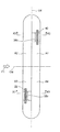
- FIG. 7 is a diagram for explaining a joining state of the winding group and the current collector plate in Example 2, and FIG. 8 is a cross-sectional view taken along lines X1-X1 and X2-X2 in FIG.
- the separation distance in the thickness direction of the wound group 3 between the connection position and the connecting position can be ensured larger than that in the first embodiment.
- the wound group 3 can be stably supported in the battery can 1 and a prismatic secondary battery with high reliability against impact and vibration can be obtained.
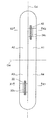
- FIG. 9 is a diagram for explaining the joining state of the winding group and the current collector plate in Example 3, and FIG. 10 is a cross-sectional view taken along lines X1-X1 and X2-X2 in FIG.
- the distance in the thickness direction of the wound group 3 between the first and second windings can be made smaller than that in the first embodiment.
- FIG. 11 is an exploded perspective view of the prismatic secondary battery in Example 4
- FIG. 12 is a diagram for explaining a joined state between the winding group and the current collector plate in Example 4.
- the joining end portion 42 of the positive current collector plate 44 and the joining end portion 22 of the negative current collector plate 24 are wound on the same side with respect to the current collector base portions 41 and 21. This is provided at the side end of the group 3 on one side in the thickness direction.
- the positive electrode current collector plate 44 has a substantially L-shaped intermediate portion 45 between the current collector plate base portion 41 and the joining end portion 42, as shown in FIGS.
- the intermediate portion 45 is arranged with the joining end portion 42 facing the inner side in the thickness direction of the wound group 3 with respect to the tab group of the positive electrode current collecting tab 34c.
- the negative electrode current collector plate 24 is arranged with the joining end portion 22 facing the outer side in the thickness direction of the wound group 3 with respect to the tab group of the negative electrode current collector tab 32c.
- the thickness of the winding group 3 that is the same side with respect to the current collector plate bases 41, 21 as the joint end portion 42 of the positive current collector plate 44 and the joint end portion 22 of the negative current collector plate 24. Since it is provided at one side end in the vertical direction, the joining end portion 42 of the positive current collector plate 44 and the joining end portion 22 of the negative current collector plate 24 are connected to the tab group of the positive current collector tab 34c and the tab of the negative current collector tab 32c. When joining the group, the joining end portion 42 does not get in the way, and the joining work can be easily performed. Further, by providing an L-shape, it is possible to increase the degree of freedom of other shapes.
- the present invention is not limited to the above-described embodiments, and various designs can be made without departing from the spirit of the present invention described in the claims. It can be changed.
- the above-described embodiment has been described in detail for easy understanding of the present invention, and is not necessarily limited to one having all the configurations described.
- a part of the configuration of an embodiment can be replaced with the configuration of another embodiment, and the configuration of another embodiment can be added to the configuration of an embodiment.
Landscapes
- Chemical & Material Sciences (AREA)
- Chemical Kinetics & Catalysis (AREA)
- Electrochemistry (AREA)
- General Chemical & Material Sciences (AREA)
- Engineering & Computer Science (AREA)
- Manufacturing & Machinery (AREA)
- Connection Of Batteries Or Terminals (AREA)
- Secondary Cells (AREA)
Abstract
La présente invention concerne une batterie très fiable qui ne présente pas de dysfonctionnement lorsqu'elle est soumise à une vibration ou à un impact. Cette batterie secondaire prismatique 100 a un groupe enroulé 3 de forme plate comprenant une électrode de pôle positif 34 et une électrode de pôle négatif 32 qui sont enroulées via des séparateurs 33, 35 placés entre les électrodes, un boîtier de batterie 1 logeant le groupe enroulé 3, un couvercle de batterie 6 étanchéifiant le boîtier de batterie 1, et, disposé sur le couvercle de batterie 6, une plaque collectrice d'électrode positive 44 et une plaque collectrice d'électrode négative 24. Ensuite, le groupe enroulé 3 est supporté par le couvercle de batterie 6 en ce qu'il a, sur une surface d'extrémité sur un côté de la direction axiale d'enroulement, une pluralité de pattes collectrices d'électrode positive 34c et une pluralité de pattes collectrices d'électrode négative 32c disposées séparément dans une paire préréglée de régions d'angle opposées A1, A3 à joindre respectivement à la plaque collectrice d'électrode positive 44 et à la plaque collectrice d'électrode négative 24.
Priority Applications (1)
| Application Number | Priority Date | Filing Date | Title |
|---|---|---|---|
| JP2016558962A JP6382336B2 (ja) | 2014-11-10 | 2015-10-28 | 角形二次電池 |
Applications Claiming Priority (2)
| Application Number | Priority Date | Filing Date | Title |
|---|---|---|---|
| JP2014-228401 | 2014-11-10 | ||
| JP2014228401 | 2014-11-10 |
Publications (1)
| Publication Number | Publication Date |
|---|---|
| WO2016076108A1 true WO2016076108A1 (fr) | 2016-05-19 |
Family
ID=55954200
Family Applications (1)
| Application Number | Title | Priority Date | Filing Date |
|---|---|---|---|
| PCT/JP2015/080308 Ceased WO2016076108A1 (fr) | 2014-11-10 | 2015-10-28 | Batterie secondaire prismatique |
Country Status (2)
| Country | Link |
|---|---|
| JP (1) | JP6382336B2 (fr) |
| WO (1) | WO2016076108A1 (fr) |
Cited By (2)
| Publication number | Priority date | Publication date | Assignee | Title |
|---|---|---|---|---|
| WO2018042928A1 (fr) * | 2016-09-05 | 2018-03-08 | 日立オートモティブシステムズ株式会社 | Batterie secondaire prismatique |
| CN116505205A (zh) * | 2022-01-25 | 2023-07-28 | 株式会社Lg新能源 | 集电板以及包括其的圆筒形二次电池 |
Citations (5)
| Publication number | Priority date | Publication date | Assignee | Title |
|---|---|---|---|---|
| JP2011065981A (ja) * | 2009-09-18 | 2011-03-31 | Samsung Sdi Co Ltd | 二次電池用電極組立体の製造方法 |
| JP2011171079A (ja) * | 2010-02-17 | 2011-09-01 | Toshiba Corp | 電池 |
| JP3187576U (ja) * | 2013-09-23 | 2013-12-05 | 迪吉亞科技股▲ふん▼有限公司 | 多極端子を備えた単巻芯及び該単巻を備えたリチウム電池 |
| JP2014032814A (ja) * | 2012-08-02 | 2014-02-20 | Toyota Industries Corp | 蓄電装置及び二次電池 |
| JP2014182993A (ja) * | 2013-03-21 | 2014-09-29 | Toyota Industries Corp | 蓄電装置 |
Family Cites Families (2)
| Publication number | Priority date | Publication date | Assignee | Title |
|---|---|---|---|---|
| JP2010118315A (ja) * | 2008-11-14 | 2010-05-27 | Toshiba Corp | 非水電解質電池 |
| JP2016051544A (ja) * | 2014-08-29 | 2016-04-11 | 日立オートモティブシステムズ株式会社 | 扁平捲回式二次電池 |
-
2015
- 2015-10-28 WO PCT/JP2015/080308 patent/WO2016076108A1/fr not_active Ceased
- 2015-10-28 JP JP2016558962A patent/JP6382336B2/ja active Active
Patent Citations (5)
| Publication number | Priority date | Publication date | Assignee | Title |
|---|---|---|---|---|
| JP2011065981A (ja) * | 2009-09-18 | 2011-03-31 | Samsung Sdi Co Ltd | 二次電池用電極組立体の製造方法 |
| JP2011171079A (ja) * | 2010-02-17 | 2011-09-01 | Toshiba Corp | 電池 |
| JP2014032814A (ja) * | 2012-08-02 | 2014-02-20 | Toyota Industries Corp | 蓄電装置及び二次電池 |
| JP2014182993A (ja) * | 2013-03-21 | 2014-09-29 | Toyota Industries Corp | 蓄電装置 |
| JP3187576U (ja) * | 2013-09-23 | 2013-12-05 | 迪吉亞科技股▲ふん▼有限公司 | 多極端子を備えた単巻芯及び該単巻を備えたリチウム電池 |
Cited By (3)
| Publication number | Priority date | Publication date | Assignee | Title |
|---|---|---|---|---|
| WO2018042928A1 (fr) * | 2016-09-05 | 2018-03-08 | 日立オートモティブシステムズ株式会社 | Batterie secondaire prismatique |
| US11322790B2 (en) | 2016-09-05 | 2022-05-03 | Vehicle Energy Japan Inc. | Prismatic secondary battery |
| CN116505205A (zh) * | 2022-01-25 | 2023-07-28 | 株式会社Lg新能源 | 集电板以及包括其的圆筒形二次电池 |
Also Published As
| Publication number | Publication date |
|---|---|
| JPWO2016076108A1 (ja) | 2017-07-06 |
| JP6382336B2 (ja) | 2018-08-29 |
Similar Documents
| Publication | Publication Date | Title |
|---|---|---|
| JP6328271B2 (ja) | 角形二次電池 | |
| JP6214758B2 (ja) | 角形二次電池 | |
| CN113287222B (zh) | 二次电池 | |
| JP6446239B2 (ja) | 二次電池 | |
| JP5779562B2 (ja) | 角形電池 | |
| WO2018062231A1 (fr) | Batterie secondaire en forme de carré | |
| JP2017188338A (ja) | 二次電池 | |
| JP6715936B2 (ja) | 角形二次電池 | |
| JP2016143618A (ja) | 角形二次電池 | |
| JP2016178053A (ja) | 角形二次電池 | |
| JP6562726B2 (ja) | 角形二次電池及びその製造方法 | |
| JP6494159B2 (ja) | 二次電池 | |
| JP6182061B2 (ja) | 二次電池 | |
| JP6216203B2 (ja) | 捲回式二次電池 | |
| JP6382336B2 (ja) | 角形二次電池 | |
| JP6606400B2 (ja) | 蓄電素子 | |
| JP6978500B2 (ja) | 二次電池 | |
| JP2016110787A (ja) | 角形二次電池 | |
| WO2015125223A1 (fr) | Batterie secondaire | |
| WO2017130702A1 (fr) | Accumulateur rectangulaire | |
| JP6504994B2 (ja) | 角形蓄電素子 | |
| JP6431089B2 (ja) | 角形二次電池 | |
| JP6360305B2 (ja) | 角形二次電池 | |
| JP6752737B2 (ja) | 角形二次電池 | |
| JP6892338B2 (ja) | 蓄電装置および蓄電装置の製造方法 |
Legal Events
| Date | Code | Title | Description |
|---|---|---|---|
| 121 | Ep: the epo has been informed by wipo that ep was designated in this application |
Ref document number: 15858319 Country of ref document: EP Kind code of ref document: A1 |
|
| ENP | Entry into the national phase |
Ref document number: 2016558962 Country of ref document: JP Kind code of ref document: A |
|
| NENP | Non-entry into the national phase |
Ref country code: DE |
|
| 122 | Ep: pct application non-entry in european phase |
Ref document number: 15858319 Country of ref document: EP Kind code of ref document: A1 |