WO2016076156A1 - 燃料電池用流路部材の製造方法 - Google Patents
燃料電池用流路部材の製造方法 Download PDFInfo
- Publication number
- WO2016076156A1 WO2016076156A1 PCT/JP2015/080932 JP2015080932W WO2016076156A1 WO 2016076156 A1 WO2016076156 A1 WO 2016076156A1 JP 2015080932 W JP2015080932 W JP 2015080932W WO 2016076156 A1 WO2016076156 A1 WO 2016076156A1
- Authority
- WO
- WIPO (PCT)
- Prior art keywords
- fuel cell
- resin
- groove
- flow path
- grooved base
- Prior art date
- Legal status (The legal status is an assumption and is not a legal conclusion. Google has not performed a legal analysis and makes no representation as to the accuracy of the status listed.)
- Ceased
Links
Images


Classifications
-
- H—ELECTRICITY
- H01—ELECTRIC ELEMENTS
- H01M—PROCESSES OR MEANS, e.g. BATTERIES, FOR THE DIRECT CONVERSION OF CHEMICAL ENERGY INTO ELECTRICAL ENERGY
- H01M8/00—Fuel cells; Manufacture thereof
- H01M8/02—Details
-
- H—ELECTRICITY
- H01—ELECTRIC ELEMENTS
- H01M—PROCESSES OR MEANS, e.g. BATTERIES, FOR THE DIRECT CONVERSION OF CHEMICAL ENERGY INTO ELECTRICAL ENERGY
- H01M8/00—Fuel cells; Manufacture thereof
- H01M8/02—Details
- H01M8/0202—Collectors; Separators, e.g. bipolar separators; Interconnectors
-
- H—ELECTRICITY
- H01—ELECTRIC ELEMENTS
- H01M—PROCESSES OR MEANS, e.g. BATTERIES, FOR THE DIRECT CONVERSION OF CHEMICAL ENERGY INTO ELECTRICAL ENERGY
- H01M8/00—Fuel cells; Manufacture thereof
- H01M8/10—Fuel cells with solid electrolytes
-
- Y—GENERAL TAGGING OF NEW TECHNOLOGICAL DEVELOPMENTS; GENERAL TAGGING OF CROSS-SECTIONAL TECHNOLOGIES SPANNING OVER SEVERAL SECTIONS OF THE IPC; TECHNICAL SUBJECTS COVERED BY FORMER USPC CROSS-REFERENCE ART COLLECTIONS [XRACs] AND DIGESTS
- Y02—TECHNOLOGIES OR APPLICATIONS FOR MITIGATION OR ADAPTATION AGAINST CLIMATE CHANGE
- Y02E—REDUCTION OF GREENHOUSE GAS [GHG] EMISSIONS, RELATED TO ENERGY GENERATION, TRANSMISSION OR DISTRIBUTION
- Y02E60/00—Enabling technologies; Technologies with a potential or indirect contribution to GHG emissions mitigation
- Y02E60/30—Hydrogen technology
- Y02E60/50—Fuel cells
-
- Y—GENERAL TAGGING OF NEW TECHNOLOGICAL DEVELOPMENTS; GENERAL TAGGING OF CROSS-SECTIONAL TECHNOLOGIES SPANNING OVER SEVERAL SECTIONS OF THE IPC; TECHNICAL SUBJECTS COVERED BY FORMER USPC CROSS-REFERENCE ART COLLECTIONS [XRACs] AND DIGESTS
- Y02—TECHNOLOGIES OR APPLICATIONS FOR MITIGATION OR ADAPTATION AGAINST CLIMATE CHANGE
- Y02P—CLIMATE CHANGE MITIGATION TECHNOLOGIES IN THE PRODUCTION OR PROCESSING OF GOODS
- Y02P70/00—Climate change mitigation technologies in the production process for final industrial or consumer products
- Y02P70/50—Manufacturing or production processes characterised by the final manufactured product
Definitions
- the present invention relates to a manufacturing method of a fuel cell flow path member, and more particularly, to a manufacturing method for forming a flow path member having good resin processing and good conductivity.
- a fuel cell is a power generator that obtains electricity by a chemical reaction between stored hydrogen or hydrogen obtained by reforming alcohol or ether, and oxygen in the air.
- Typical fuel cells include a phosphoric acid fuel cell (PAFC), a molten carbonate fuel cell (MCFC), a solid oxide fuel cell (SOFC), and a polymer electrolyte fuel cell (PEFC).
- PAFC phosphoric acid fuel cell
- MCFC molten carbonate fuel cell
- SOFC solid oxide fuel cell
- PEFC polymer electrolyte fuel cell
- the polymer electrolyte fuel cell is suitable for miniaturization as compared with other types. Therefore, the polymer electrolyte fuel cell is suitable for mounting on a transport machine such as a passenger car that is subject to many restrictions on installation locations.
- separators are provided on both sides of a fuel electrode (negative electrode / anode) for supplying hydrogen and an air electrode (positive electrode / cathode) for supplying oxygen.
- the membrane electrode assembly (MEA: Membrane Electrode Assembly) is sandwiched between both separators.
- This membrane electrode assembly is configured by stacking a catalyst layer, a water repellent layer on both sides of a proton conductive film, and a gas diffusion layer on the outside thereof. A necessary number of these combinations are connected to form a fuel cell (see, for example, Patent Documents 1 and 2).
- the surface area of the flow path is expanded by using fine flow paths. Further, by forming a fine flow path, it is possible to incorporate it into a battery such as the membrane electrode assembly described above. If it does so, the heat_generation
- the present invention has been proposed in view of the above situation, and is more convenient in combination with a separator of a polymer electrolyte fuel cell and a membrane electrode assembly while ensuring conductivity, and forming a finer flow path.
- the present invention provides a fuel cell flow path member manufacturing method that is suitable for the distribution of various fluids such as hydrogen, oxygen, and a cooling refrigerant, and that is inexpensive and simple to manufacture.
- the invention of claim 1 includes a step of obtaining a sheet-like first conductive portion containing a first resin and a carbon material, and a second resin and a carbon material having a lower melting point than the first resin.
- a step of covering the groove portion by integrating the grooved base portion and the third conductive portion by heat fusion.
- the invention of claim 2 relates to a method of manufacturing a fuel cell flow path member according to claim 1, wherein the groove is provided on the side of the grooved base portion on which the second conductive portion is laminated.
- the invention of claim 3 relates to a method of manufacturing a fuel cell flow path member according to claim 1, wherein the groove portions are provided on both surfaces of the grooved base portion.
- a fourth aspect of the present invention relates to the fuel cell channel member manufacturing method according to the first aspect, wherein the groove portion is provided on a surface of the grooved base portion opposite to a surface on which the second conductive portion is laminated. .
- the present invention in the fuel cell according to the first aspect, in place of the third conductive portion, another grooved base portion is laminated on a surface side of the grooved base portion where the groove portion is formed.
- the present invention relates to a method for manufacturing a flow path member.
- the invention of claim 7 relates to the method of manufacturing a fuel cell channel member according to claim 6, wherein the uneven groove portion has a structure in which the groove portion and the stripe portion are continuous in parallel.
- the invention according to claim 8 is the method for manufacturing a fuel cell flow path member according to claim 6, wherein the groove depth of the uneven groove portion is 50 to 200 ⁇ m, and the groove width of the uneven groove portion is 100 to 400 ⁇ m. Concerning.
- the invention of claim 10 relates to the method of manufacturing a fuel cell flow path member according to claim 9, wherein the metal plate is provided with an adhesive resin layer containing a carbon material.
- the invention of claim 11 relates to the fuel cell channel member manufacturing method according to claim 1 or 10, wherein the carbon material is at least one of carbon nanotubes, granular graphite, and carbon fibers.
- a step of obtaining a sheet-like first conductive part containing the first resin and the carbon material, and a lower melting point than the first resin A step of laminating a sheet-like second conductive part containing a second resin and a carbon material on at least one surface side of the first conductive part to form a sheet-like base part; and a surface of the base part
- a step of transferring the groove mold surface to form a grooved base portion provided with a groove portion; and a sheet-like third conductive portion containing a third resin having a melting point lower than that of the first resin and a carbon material A step of laminating a sheet-like second conductive part containing a second resin and a carbon material on at least one surface side of the first conductive part to form a sheet-like base part; and a surface of the base part
- a fuel cell channel member that is highly convenient, can be formed into finer channels, is suitable for the distribution of various fluids such as hydrogen, oxygen, and cooling refrigerant, and is inexpensive and simple to manufacture. Can be produced.
- the groove portion is provided on the surface side of the grooved base portion on which the second conductive portion is laminated. Heat sealing with the sheet-like third conductive portion described later and covering the groove portion are facilitated.
- the groove portion is provided on both surfaces of the grooved base portion, a plurality of channels are formed by batch processing. It can be easily formed in the vertical direction.
- the groove portion is formed on a surface opposite to the surface on which the second conductive portion is laminated in the grooved base portion. Since it is provided, it is convenient for combination with another member in the fuel cell in addition to the other grooved base portion.
- the grooved base portion is laminated instead of the third conductive portion.
- the grooved base portion is laminated instead of the third conductive portion.
- the groove is an uneven groove, it can be formed relatively easily, and waste is not easily generated. There are advantages.
- the concave and convex groove portion has a structure in which the groove portion and the strip portion are continuous in parallel, the mold itself The manufacturing burden is reduced.
- the groove depth of the uneven groove portion is 50 to 200 ⁇ m, and the groove width of the uneven groove portion is 100. Therefore, it is appropriate from the viewpoint of the cooling efficiency by supplying the cooling refrigerant in the fuel cell and the efficiency of supplying and diffusing hydrogen and oxygen to the separator and membrane electrode assembly.
- the fuel cell flow path member manufacturing method of the ninth aspect of the invention in the first aspect of the invention, since the grooved base portion is provided with the metal plate, the fuel cell flow path member is fixed. It can be used as a holding part. Moreover, it is convenient for connection with external wiring.
- the metal plate is provided with an adhesive resin layer containing a carbon material.
- the conductivity is increased.
- the carbon material is at least one of carbon nanotubes, granular graphite, or carbon fibers. Even though the conductive portion is formed of a resin material, conductivity can be obtained due to the carbon material.
- the fuel cell flow path member manufactured according to the present invention is a member mainly incorporated in a polymer electrolyte fuel cell (PEFC). Therefore, the flow path is for supplying hydrogen and oxygen for power generation by an electrochemical reaction and further supplying a cooling medium such as water for temperature control of the fuel cell.
- the characteristics of the flow path member are that it is inexpensive and has electrical conductivity while adopting a relatively simple structure. First, the structure of each conductive portion and the manufacturing process will be described.
- FIG. 1 is a partially enlarged schematic cross-sectional view showing an outline of each conductive portion of a fuel cell channel member such as a first conductive portion described below.
- carbon nanotubes 2 Carbon nanotubes
- a resin 1 first resin, which will be described later.
- granular graphite 3 spherical graphite
- carbon fiber 4 Carbon fiber
- the carbon nanotube 2 is a carbon compound composed of only carbon atoms having a diameter of 10 nm to 150 nm. Carbon nanotubes occupy 15 to 30% by weight of the total weight of each conductive part. If the amount of carbon nanotubes is excessively increased, the viscosity of the resin will increase, which tends to cause molding defects. Therefore, the above range is desirable.
- the carbon nanotube itself has conductivity. However, it is about 1/1000 the size of other carbon materials and very fine. Rather than improving the electrical conductivity of the resin itself with only carbon nanotubes, it is added to each conductive part for the purpose of assisting the electrical conductivity of the granular graphite 3 or the carbon fiber 4 described below.
- the granular graphite 3 is a substantially spherical graphite, and its diameter (particle diameter) is 5 ⁇ m or more, preferably 10 to 30 ⁇ m.
- the weight ratio of the granular graphite in the total weight of each conductive part is 30 to 60% by weight.
- the granular graphites are arranged close to or in contact with each other in each conductive part, and the direct conductivity is improved.
- the carbon fiber 4 is a fibrous material obtained by carbonizing resin fibers, and the fiber diameter (cross-sectional diameter) is about 5 to 30 ⁇ m.
- the fiber length is approximately 50 to 200 ⁇ m.
- the weight ratio of the carbon fiber to the total weight of each conductive part is 5 to 30% by weight.
- the carbon fibers are also arranged close to or in contact with each other in each conductive part, and the conductivity is improved. Moreover, since it is fibrous, a network structure is formed in the conductive part, which contributes to strength improvement.
- FIG. 1 (a), (b), or (c) The structure of FIG. 1 (a), (b), or (c) is adopted for the first conductive portion, the second conductive portion, or the third conductive portion described in FIG. In consideration of the properties of the resin, etc. Of course, although not shown, it is good also as a mixture of only one kind of carbon material. In order to further increase the electrical conductivity and ensure the strength of the conductive portion, it is desirable to combine two or more types of carbon materials as illustrated.
- each conductive part is non-conductive.
- the insulating region also increases.
- the upper limit is defined from the viewpoint of maintaining the strength of the conductive portion.
- the space between the granular graphites or the carbon fibers spreads.
- the addition of carbon nanotubes creates a new path for electrons that connect between the graphite particles or carbon fibers that are present apart from each other. Therefore, more preferred is a blend of carbon nanotubes and spherical graphite, or carbon nanotubes and carbon fibers, and even more preferred is a blend of all types of carbon nanotubes, granular graphite, and carbon fibers.
- FIG. 2A a sheet-like first conductive portion 11 containing the carbon material and the first resin (R1) is formed.
- the first resin (R1) is a resin that constitutes the main part of the fuel cell flow path member. Therefore, it is selected from resins that are relatively excellent in durability and easy to process. For example, ethylene homopolymer, propylene homopolymer (homopolypropylene), ethylene and propylene, 1-butene, 1-pentene, 1-hexene, 4-methyl-1-pentene, etc. Examples thereof include random copolymers with olefins and block copolymers having the above composition. Further, it is a polyolefin resin such as a mixture of these polymers described above, and a hydrocarbon resin such as petroleum resin and terpene resin.
- At least one or more of carbon nanotubes, granular graphite, or carbon fiber is added to the first resin (R1) as the carbon material described above. Then, the carbon material is contained in the first resin to form the sheet-like first conductive portion 11 (step of FIG. 2A).
- a second resin (R2) having a lower melting point than the first resin (R1) is prepared.
- This second resin is a resin used for the purpose of heat fusion.
- the second resin corresponds to the adhesive for the first conductive portion 11.
- the second resin (R2) can also be selected from acid-modified polyolefin resins.
- the acid-modified polyolefin resin a polyolefin-based resin modified with an unsaturated carboxylic acid or a derivative thereof is preferably used.
- unsaturated carboxylic acids include acrylic acid, methacrylic acid, maleic acid, fumaric acid, crotonic acid, itaconic acid, citraconic acid, and the like, and esters and anhydrides thereof can also be used.
- examples of the derivatives include methyl acrylate, methyl methacrylate, ethyl acrylate, propyl acrylate, butyl acrylate, butyl methacrylate, vinyl acetate, glycidyl acrylate, glycidyl methacrylate, acrylamide, methacrylamide, sodium acrylate, and the like. It is done.
- the amount of the unsaturated carboxylic acid or derivative thereof contained in the polyolefin resin is preferably 0.001 to 3% by weight, more preferably 0.01 to 1% by weight, particularly preferably 0.03 to 0%. .5% by weight.
- Adhesive properties can be improved by blending these adhesive resins with rubber and elastomer components such as polyisobutylene and ethylene-propylene rubber, and polyolefin resins that are different from the base polyolefin resin of the adhesive resin. It is useful.
- the second resin (R2) at least one of carbon nanotubes, granular graphite, or carbon fibers is added as the above-described carbon material. And the carbon material is contained in the second resin, and the sheet-like second conductive portion 21 is formed.
- the second conductive portion 21 is stacked on at least one surface side of the first conductive portion 11.
- the sheet-like base portion 13 is formed (step of FIG. 2B).
- a mold 50 is prepared for forming a flow path in the flow path member.
- the mold 50 is provided with a concave and convex groove-shaped surface 51 in a comb-like shape.
- the mold 50 is pressed against the surface of the flat sheet-like base portion 13.
- the groove mold surface 51 of the mold 50 is transferred to the base portion 13 to form the groove portion 15.
- another smooth plate-shaped mold 55 is prepared and pressed on the surface where the groove mold surface is not transferred.
- the pressing using the mold is performed at a stage where the fluidity of the constituent resin of the base portion 13 is provided.
- the grooved base portion 16 having the groove portion 15 is formed (step of FIG. 2C).
- the groove portion 15 is provided on the surface side on which the second conductive portion 21 is laminated. Since the groove portion is formed on the surface side, it becomes easy to heat-seal the groove-shaped third conductive portion and cover the groove portion.
- the groove mold surface 51 of the mold 50 shown in the figure has a continuous uneven shape, and each of the strips is parallel.
- the groove surface 51 of the mold 50 is transferred to the base portion 13, and an uneven groove portion Su in which the groove portion 15 (groove bottom) and the strip portion 19 continue in parallel is formed in the base portion 13.
- This shape can be formed relatively easily, and waste is hardly generated.
- the manufacturing burden of the mold itself is reduced.
- the size of the concavo-convex groove portion is appropriate, the groove depth is 50 to 200 ⁇ m and the groove width is 100 to 400 ⁇ m. These sizes are appropriate from the efficiency of cooling by supplying the cooling refrigerant in the fuel cell and the efficiency of supplying and diffusing hydrogen and oxygen to the separator and membrane electrode assembly.
- the concavo-convex groove portion has a structure in which the groove portion and the stripe portion are continuous in parallel.
- the shape of the groove surface of the mold is not limited to that shown in the figure and can be a required shape.
- the groove surface may be a continuous zigzag shape or the like.
- a third resin (R3) having a lower melting point than the first resin (R1) is prepared.
- the third resin is a resin that is heat-sealed with the second conductive portion.
- the compatibility between the third resin (R3) and the second resin (R2), the difficulty of peeling, etc., the low melting point and the same type of resin as the first resin, or the low melting point and the same type of resin as the second resin Is desirable.
- it can also be selected from acid-modified polyolefin resins similar to the second resin.
- the third resin (R3) at least one kind of carbon nanotube, granular graphite, or carbon fiber is added as the carbon material.
- the third resin also contains a carbon material to form a sheet-like third conductive portion 31.
- the 3rd electroconductive part 31 is laminated
- the groove portion 15 of the grooved base portion 16 is covered with the third conductive portion 31. That is, the third conductive portion 31 becomes a lid for the groove portion 15.
- the groove portion 15 becomes a pipe-like fluid flow path 18, and the fuel cell flow path member 10A is completed.
- the second resin (R2) of the second conductive portion 21 is heated.
- the third resin (R3) of the third conductive part 31 has a lower melting point than the first resin (R1) of the first conductive part 11, and therefore melts relatively faster than the first resin (R1). .
- the fusion of the second conductive portion 21 and the third conductive portion 31 of the grooved base portion 16 proceeds.
- the first conductive portion 11 of the grooved base portion 16 is not melted and the original shape is maintained.
- the groove portion can be easily covered and closed by utilizing the melting point difference.
- the melting point of the resin in the series of explanations is a value obtained by differential scanning calorimetry (DSC).
- DSC differential scanning calorimetry
- a desired carbon material is Predetermined amounts are weighed, kneaded by a heat-meltable blender or kneader, and homogenized in the resin. Thereafter, the kneaded product of each resin is laminated through co-extrusion from a T die or the like. Alternatively, the kneaded product of each resin is laminated as a single body, passed through a rolling roller or the like, and rolled until it reaches a predetermined thickness. For these processes, an appropriate technique and apparatus for resin processing are used.
- FIG. 3 is a schematic sectional view of the grooved base portion 16b of the second embodiment.
- a groove portion 15 first groove portion
- a groove portion 17 second groove portion
- FIG. 4 is a schematic cross-sectional view of the grooved base portion 16c of the third embodiment.
- the groove portion 17 second groove portion
- the groove portion 17 is provided on the surface opposite to the surface on which the second conductive portion 21 is laminated.
- the groove portions are provided on both surfaces as in the grooved base portion 16b, even if the groove directions of the respective groove portions are the same (FIG. 3A), they may be formed so as to be orthogonal to each other (that is, shifted by a predetermined angle). (FIG. 3B).
- the grooved base portion 16b of the second embodiment When the grooved base portion 16b of the second embodiment is adopted, a plurality of flow paths can be easily formed in the vertical direction by batch processing.
- the grooved base portion 16c of the third embodiment is convenient for combination with another member in the fuel cell in addition to the other grooved base portion.
- aggregation can be performed for each flow path such as an oxygen flow path and a hydrogen flow path, which further helps to reduce the member volume.
- the second conductive portion 21 can be laminated on both sides (not shown). In this case, lamination by heat fusion becomes easier.
- FIG. 5 is a schematic cross-sectional view of the fuel cell flow path member 10B of the second embodiment.
- the grooved base portion 16b (see FIGS. 3 and 4) is combined with the grooved base portion 16b in a stacked manner.
- the fuel cell channel member 10B is formed by heat fusion.
- the groove portion 15 is closed at the central portion to form a pipe-like fluid flow path 18.
- the grooves 17 and 15 are exposed on both surfaces of the fuel cell channel member 10B in the vertical direction.
- it is convenient for the combination with another member in the fuel cell.
- it can be used as a groove for air cooling.
- the second conductive portion 21 can be laminated on both sides (not shown).
- FIG. 6 is a schematic cross-sectional view of a fuel cell flow path member 10C of the third embodiment.
- the groove width itself is increased while the shape of the groove itself is a continuous uneven shape.
- the groove portion 19 (between the groove portions) of the grooved base portion 16e in which the groove portion 15e is formed on only one side is combined with the central portion of the groove portion of the grooved base portion 16d in which the groove portions 15d and 17d and the groove portion 19d are formed on both surfaces.
- any member is a resin processed product, the shape design is easy.
- the area of the longitudinal cross-section of a flow path can also be adjusted suitably by replacing
- the second conductive portion 21 is laminated on both surfaces.
- FIG. 7 is a schematic cross-sectional view of a fuel cell flow path member 10D of the fourth embodiment
- FIG. 8 is a cross-sectional schematic view of a fuel cell flow path member 10E of the fifth embodiment.
- the metal plate 40 is provided inside the grooved base portions 16f and 16g.
- the metal plate is used as a holding portion when connecting and fixing the fuel cell flow path member to the fuel cell.
- electrons can move in the metal plate, they are connected to external wiring. For example, it is effective for serial connection. Corrosion resistance and the like are considered for the material of the metal plate. Therefore, a metal plate such as a stainless steel plate, a titanium plate, or an aluminum plate is used.
- a metal plate for example, a gold-plated stainless steel plate obtained by subjecting the metal plate to a surface treatment such as gold plating, nickel plating, or carbon plating is also preferably used.
- the thickness of the metal plate is in the range of about 8 to 200 ⁇ m. When the thickness of the metal plate is reduced, the volume of the fuel cell itself can be reduced, and the power generation performance per battery volume can be increased.
- An adhesive resin layer 45 is preferably interposed between the first resin (R1) and the metal plate 40 in the grooved base portion 16f (16g). The adhesive resin layer enhances the adhesion between both the grooved base portion and the metal plate.
- the constituent resin of the adhesive resin layer 45 is selected from acid-modified polyolefin resins that are components of the second resin (R2) or the third resin (R3) described above.
- the acid-modified polyolefin resin is a polyolefin resin modified with an unsaturated carboxylic acid or a derivative thereof.
- the illustration of the corresponding resin type will be omitted for convenience of overlapping explanation.
- the resin of the adhesive resin layer 45 at least one of carbon nanotubes, granular graphite, or carbon fibers is added as a carbon material. This is to increase the conductivity of the adhesive resin layer 45 itself.
- the thickness of the adhesive resin layer 45 is adjusted at the extrusion molding and rolling stage. If it is too thick, the conductivity deteriorates even if it contains a carbon material. Therefore, the thickness of the adhesive resin layer 45 is approximately 100 ⁇ m or less, more preferably 50 ⁇ m or less.
- the acid-modified polyolefin resin has a polar group. For this reason, adhesion is strengthened by the influence of ionic bonding between the polar group of the resin and the metal atom.
- a resin sheet that will later become the adhesive resin layer 45 is disposed on both surfaces or one surface of the metal plate 40. These are carried in between a heating board and a heating roller, and heat fusion is performed. Thus, an integrated product of the metal plate 40 and the adhesive resin layer 45 is completed.
- the sheet-like first conductive portion 11 is laminated on both surfaces or one surface of the adhesive resin layer 45 integrated with the metal plate 40.
- a sheet-like second conductive portion 21 is also stacked on the first conductive portion 11.
- the first conductive portion 11 and the second conductive portion 21 may be stacked by stacking separate sheet-like materials or simultaneously extruding from a T die or the like.
- the sheet-like base portions 13f and 13g provided with the metal plate 40 are formed.
- a grooved surface is transferred to the base portions 13f and 13g to form grooved base portions 16f and 16g.
- FIG. 7 a grooved base portion 16f having groove portions 15 and 17 on both sides is prepared.
- the third conductive portion 31 is stacked on the surface side of the grooved base portion 16f where the second conductive portion 21 is stacked. Thereafter, similarly, the groove portion 15 of the grooved base portion 16f is covered with the third conductive portion 31 by integration accompanying heat fusion.
- FIG. 8 is an example corresponding to FIG. 5 described above, and two members are formed: a grooved base portion 16f having groove portions 15 and 17 on both surfaces, and a grooved base portion 16g having groove portions 15 on one surface.
- a surface side on which the second conductive portion 21 of the grooved base portion 16f is laminated and a surface side on which the second conductive portion 21 of the grooved base portion 16g is laminated. Can be pasted together.
- the groove portion 15 of the grooved base portion 16f is covered with the grooved base portion 16g by the integration accompanying heat fusion.
- the second conductive portion 21 can be laminated on both surfaces (not shown).
- FIG. 9 is a schematic sectional view of a fuel cell flow path member 10F of the fifth embodiment.
- the metal plate 40 is exposed to the outside.
- the adhesive resin layer 45, the first conductive portion 11 (first resin), and the second conductive portion 21 (second resin) are laminated on the metal plate 40 in this order.
- the groove mold surface is transferred to form the groove 15.
- the 3rd electroconductive part 31 is laminated
- the processing method in the fuel cell channel members 10D, 10E, and 10F disclosed in FIGS. 7 to 9 is the same as that of the fuel cell channel member 10A (see FIG. 2).
- the fuel cell channel member ensures conductivity while using resin, and allows a free shape design. Therefore, it can be adapted to the optimum form for the part required in the fuel cell. Therefore, it is not limited to the flow path of the cooling medium such as water, but can be effectively used for supplying oxygen and hydrogen, and exhausting the generated water vapor.
- Example 1 in accordance with the structures ([I] to [V]) in the cross-sectional schematic diagrams of FIGS. 10 and 11 based on the formulations disclosed in Tables 1 to 3 below.
- Example 1 to 8 were prepared.
- the fuel cell flow path member of each Example and a comparative example it is the structure (any one of [I] thru
- Carbon nanotube VGCF-X manufactured by Showa Denko KK (fiber diameter: 10 to 15 nm, hereinafter referred to as “CNT”)
- Granular graphite manufactured by Nippon Carbon Co., Ltd., Nikabeads P25B-ZG (average particle size: 25 ⁇ m, true density: 2.17 g / cm 3 , hereinafter referred to as “SG”)
- Carbon fiber manufactured by Mitsubishi Plastics Co., Ltd., DIALEAD K223HE (fiber diameter: 11 ⁇ m, true density: 2.0 g / cm 3 , hereinafter referred to as “CF”)
- a stainless steel plate (SUS316L, thickness 100 ⁇ m) with gold plating on both surfaces was used.
- gold plated stainless steel sheet A stainless steel plate (SUS316L, thickness 100 ⁇ m) with gold plating on both surfaces was used.
- gold plated stainless steel sheet Aluminum foil (manufactured by UACJ Co., Ltd., “Nippaku foil”, thickness 12 ⁇ m) was used. Hereinafter, it is referred to as “aluminum foil”.
- the mold for forming the groove part was formed into a continuous groove-shaped surface shape having a rectangular shape (rectangular shape) in cross-section with a space between the grooves of 350 ⁇ m, a groove width of 200 ⁇ m, and a groove depth of 100 ⁇ m.
- the smooth surface mold was left flat.
- the mold was common to all examples and comparative examples.
- the metal plate 40, the adhesive resin layer 45, the first conductive portion 11, and the second conductive portion 21 are laminated in this order to produce a grooved base portion 16x having the groove portion 15.
- the metal plate 40 provided with the adhesive resin layer 45 as the third conductive portion 31 was laminated and integrated by heat fusion (structure [I]).
- a grooved base portion 16x provided with a groove portion 15 was prepared by laminating the metal plate 40, the adhesive resin layer 45, the first conductive portion 11, and the second conductive portion 21 in this order.
- the composite 33 provided with the third conductive portion 31 was laminated on the sheet-like material 32 of the first resin containing the carbon material, and integrated by heat fusion (structure [II]).
- a grooved base portion 16 x provided with a groove portion 15 was produced by laminating the metal plate 40, the adhesive resin layer 45, the first conductive portion 11, and the second conductive portion 21 in this order.
- the metal plate 40 was laminated and integrated by thermal fusion (structure [III]).
- a grooved base portion 16x provided with a groove portion 15 was produced by laminating the metal plate 40, the adhesive resin layer 45, the first conductive portion 11 and the second conductive portion 21 in this order.
- the sheet-like material 32 of the first resin containing the carbon material was laminated and integrated by heat fusion (structure [IV]).
- a grooved base portion 16 y provided with a groove portion 15 was produced by laminating the metal plate 40, the adhesive resin layer 45, and the first conductive portion 11 in this order.
- the metal plate 40 provided with the adhesive resin layer 45 was laminated and integrated by heat fusion (structure [V]).
- Example 1 114 parts by weight of carbon nanotubes (CNT) and 241 parts by weight of granular graphite (SG) were mixed with 100 parts by weight of the first resin (PP) and uniformly kneaded while heating to 170 ° C. The sheet was passed through a calender roll machine heated to a temperature 1 to 5 ° C. lower than the melting point of the resin to obtain a sheet-like first conductive part having a thickness of 60 ⁇ m.
- CNT carbon nanotubes
- SG granular graphite
- the second conductive part and the adhesive resin layer are common, 100 parts by weight of maleic anhydride-modified low density polyethylene (modified LL), 73 parts by weight of carbon nanotubes (CNT), 159 parts by weight of granular graphite (SG), and carbon 123 parts by weight of fiber (CF) was blended and uniformly kneaded while heating to 140 ° C.
- the kneaded product was passed through a calender roll machine heated to a temperature 1 ° C. to 5 ° C. lower than the melting point of the resin to obtain a sheet-like second conductive portion and an adhesive resin layer having a thickness of 20 ⁇ m.
- a metal plate gold-plated stainless steel plate
- an adhesive resin layer a first conductive part, and a second conductive part are laminated in this order, and a release PET film (thickness 25 ⁇ m) is provided between the second conductive part and the mold.
- the whole laminate was bonded by heating and pressing from above and below using a mold having a flat plate shape and a groove mold surface.
- the pressing temperature at this time was set to 20 ° C. higher than the melting point of the first resin (PP).
- the press pressure was 30 MPa.
- a grooved base portion was produced.
- interval of grooves was 350 micrometers
- the groove width was 200 micrometers
- a metal plate gold-plated stainless steel plate
- an adhesive resin layer were laminated and bonded together by hot pressing from above and below using a flat plate mold.
- the pressing temperature at this time was set to 20 ° C. higher than the melting point of maleic anhydride-modified low density polyethylene (modified LL).
- the press pressure was 30 MPa. In this way, a third conductive portion provided with a metal plate was produced.
- the grooved base portion and the third conductive portion were integrated by heat pressing from above and below using a flat plate mold.
- the temperature was set to 130 ° C. and the press pressure was set to 2.4 MPa.
- a fuel cell channel member having the structure [I] in FIG. 10A was produced (Example 1).
- Example 2 ⁇ Example 2>
- the grooved base portion and the third conductive portion are common to those in Example 1 described above.
- the temperature was 140 ° C. and the pressing pressure was 2.4 MPa.
- a fuel cell channel member having the structure [I] in FIG. 10A was produced (Example 2).
- Example 3 In Example 3, the grooved base part and the third conductive part were shared with Example 1 described above. During the heat pressing of the grooved base portion and the third conductive portion, the temperature was 150 ° C. and the pressing pressure was 2.4 MPa. As a result, a fuel cell channel member having the structure [I] in FIG. 10A was produced (Example 3).
- Example 4 ⁇ Example 4>
- the grooved base part and the third conductive part were made common to Example 1 described above.
- the temperature was 140 ° C. and the pressing pressure was 3.1 MPa.
- a fuel cell channel member having the structure [I] in FIG. 10A was produced (Example 4).
- Example 5 In Example 5, the first conductive part and the third conductive part are the same as those in Example 1 described above, and the resin of the second conductive part is low density polyethylene (LL).
- the kneaded product was passed through a calender roll machine heated to a temperature 1 ° C. to 5 ° C. lower than the melting point of the resin to obtain a sheet-like second conductive part having a thickness of 20 ⁇ m.
- a metal plate (gold-plated stainless steel plate), an adhesive resin layer, a first conductive portion, and a second conductive portion are stacked in this order, and heated and pressed from above and below using a die having a flat plate shape and a grooved surface.
- the entire laminate was glued.
- the pressing temperature at this time was set to 20 ° C. higher than the melting point of the first resin (PP).
- the press pressure was 30 MPa.
- a grooved base portion was produced.
- a metal plate (gold-plated stainless steel plate) and an adhesive resin layer were laminated and bonded together by hot pressing from above and below using a flat plate mold.
- the pressing temperature at this time was set to 20 ° C. higher than the melting point of maleic anhydride-modified low density polyethylene (modified LL).
- the press pressure was 30 MPa. In this way, a third conductive portion provided with a metal plate was produced.
- the grooved base portion and the third conductive portion were integrated by heat pressing from above and below using a flat plate mold. During the heating press, the temperature was set to 145 ° C. and the press pressure was set to 2.4 MPa. As a result, a fuel cell flow path member having the structure [I] in FIG. 10A was produced (Example 5).
- Example 6 the grooved base part was manufactured by using the first conductive part and the second conductive part in common with Example 1 described above.
- the third conductive part was a composite including a third conductive part on a sheet of a first resin containing a carbon material. About the 1st resin sheet-like material containing a carbon material, it was made common with the 1st electroconductive part of Example 1.
- FIG. The third conductive part is common to the second conductive part of Example 5. In producing the composite of the third conductive part, it was passed through a calender roll machine heated to a temperature 1 to 5 ° C. lower than the melting point of the resin to obtain a sheet-like composite having a thickness of 20 ⁇ m.
- the grooved base portion and the composite serving as the third conductive portion were integrated by heat pressing from above and below using a flat plate mold. During the heating press, the temperature was set to 145 ° C. and the press pressure was set to 2.4 MPa. As a result, a fuel cell channel member having the structure [II] in FIG. 10B was produced (Example 6).
- Example 7 Production of the grooved base portion and the third conductive portion in Example 7 was the same as in Example 1 described above. However, the two metal plates used were changed from gold-plated stainless steel plates to aluminum foil. That is, the third conductive portion of Example 7 is an aluminum foil coated with an adhesive resin layer. During the hot pressing of the grooved base portion and the third conductive portion, the temperature was 130 ° C. and the pressing pressure was 2.4 MPa. As a result, a fuel cell channel member having the structure [I] in FIG. 10A was prepared (Example 7).
- Example 8 Production of the grooved base portion and the third conductive portion in Example 8 was the same as in Example 1 described above. However, only the metal plate laminated
- Comparative Example 1 In Comparative Example 1, the grooved base portion and the third conductive portion were common to the above-described Example 1. During the heat pressing of the grooved base portion and the third conductive portion, the temperature was set to 100 ° C. and the pressing pressure was set to 2.4 MPa. Therefore, although an attempt was made to produce a fuel cell channel member having the structure [I] in FIG. 10A, both were not thermally fused (Comparative Example 1).
- Comparative Example 2 In Comparative Example 2, the grooved base portion and the third conductive portion are common to those in Example 1 described above. During the heat pressing of the grooved base portion and the third conductive portion, the temperature was set to 165 ° C. and the pressing pressure was set to 2.4 MPa. As a result, a fuel cell channel member having the structure [I] in FIG. 10A was produced (Comparative Example 2).
- Comparative Example 3 In Comparative Example 3, the grooved base portion and the third conductive portion are common to those in Example 1 described above. During the hot pressing of the grooved base portion and the third conductive portion, the temperature was 140 ° C. and the pressing pressure was 4.1 MPa. As a result, a fuel cell channel member having the structure [I] in FIG. 10A was produced (Comparative Example 3).
- ⁇ Comparative example 4> In Comparative Example 4, a grooved base part was manufactured by using the first conductive part and the second conductive part in common with Example 1 described above. Instead of the third conductive part, only a metal plate (gold-plated stainless steel plate) was used. The grooved base portion and the metal plate were integrated by heating and pressing from above and below using a flat plate mold. During the hot pressing, the temperature was 140 ° C. and the pressing pressure was 2.5 MPa. As a result, a fuel cell channel member having the structure [III] in FIG. 11A was produced (Comparative Example 4).
- Comparative Example 5 In Comparative Example 5, the member used was common to Comparative Example 4. During the hot pressing, the temperature was 140 ° C. and the pressing pressure was 3.5 MPa. As a result, a fuel cell channel member having the structure [III] in FIG. 11A was produced (Comparative Example 5).
- Comparative Example 6 a grooved base portion was manufactured by using the first conductive portion and the second conductive portion in common with Example 1 described above. Instead of the third conductive part, only the first resin sheet was used. This first resin sheet was the same as in Example 6. The grooved base portion and the first resin sheet were integrated by heating and pressing from above and below using a flat plate mold. During the heating press, the temperature was 140 ° C. and the press pressure was 2.4 MPa. As a result, a fuel cell channel member having the structure [IV] in FIG. 11B was produced (Comparative Example 6).
- Comparative Example 7 In Comparative Example 7, the member used was common with Comparative Example 6. During the heating press, the temperature was set to 165 ° C., and the press pressure was set to 2.4 MPa. As a result, a fuel cell channel member having the structure [IV] in FIG. 11B was produced (Comparative Example 7).
- Comparative Example 8 the second conductive portion was omitted from the grooved base portion of Example 1.
- a metal plate (gold-plated stainless steel plate), an adhesive resin layer, and a first conductive part are laminated in this order, and the whole laminate is bonded by heating and pressing from above and below using a die having a flat plate shape and a grooved surface. did.
- the pressing temperature at this time was set to 20 ° C. higher than the melting point of the first resin (PP).
- the press pressure was 30 MPa.
- the 3rd electroconductive part provided with the metal plate common to Example 1 was integrated into this by heat-pressing from the upper and lower sides using the flat metal mold
- the fuel cell channel member of each example and comparative example was measured using a thickness measuring instrument (B-1 manufactured by Toyo Seiki Seisakusho Co., Ltd.), and the thickness ( ⁇ m) of each was determined.
- Comparative Example 4 has a structure in which the grooved base portion has the second conductive portion and only the metal plate is laminated thereon. From this, it was found that the adhesiveness is not sufficient only by fusing the resin of the second conductive part. In Comparative Example 5, although the pressure during the hot pressing was further increased as compared with Comparative Example 4 described above, sufficient adhesiveness could not be obtained.
- Comparative Example 6 is a first resin sheet having a second conductive portion in a grooved base portion and containing a carbon material. It has been found that even if the object of lamination is also a resin, adhesion is not sufficient only by fusing the resin of the second conductive part. In Comparative Example 7, although the pressure during the hot pressing was further increased as compared with Comparative Example 6 described above, sufficient adhesiveness could not be obtained.
- Comparative Example 8 is a grooved base portion in which the second conductive portion is omitted, and is an example in which a metal plate is laminated thereon. Even if an adhesive resin layer was provided on the metal plate side, sufficient adhesion could not be obtained.
- the temperature at the time of final heat pressing needs to be lower than the melting point of the resin of the main body portion of the grooved base part and higher than the melting point of the resin contributing to adhesion between the members. Considering these points, it is possible to suppress inadvertent shape deformation of the member and to form a good flow path inside. Furthermore, even if a metal plate was interposed in the member, good adhesion was exhibited by heat fusion. Therefore, it can be said that the fuel cell channel member is extremely convenient as a member to be incorporated into the fuel cell.
- a member having a fine flow path can be produced very easily and inexpensively from the selection of each member and the melting point difference. Therefore, it is promising as a member suitable for the distribution of various fluids such as a fuel such as hydrogen and oxygen supplied to the fuel cell and a cooling refrigerant. Of course, besides this, it can be used for various applications that require the characteristics of the present invention.
Landscapes
- Life Sciences & Earth Sciences (AREA)
- Engineering & Computer Science (AREA)
- Manufacturing & Machinery (AREA)
- Sustainable Development (AREA)
- Sustainable Energy (AREA)
- Chemical & Material Sciences (AREA)
- Chemical Kinetics & Catalysis (AREA)
- Electrochemistry (AREA)
- General Chemical & Material Sciences (AREA)
- Fuel Cell (AREA)
Abstract
Description
第1樹脂として、ホモポリプロピレン(日本ポリプロ株式会社製,ノバテックFL100A,融点161℃、以下「PP」とする。)を使用した。
第1樹脂よりも低融点の第2樹脂または第3樹脂として、以下の樹脂を使用した。
無水マレイン酸変性低密度ポリエチレン(三菱化学株式会社製,モディックM504,融点121℃、以下「変性LL」とする。)を使用した。
低密度ポリエチレン(宇部丸善ポリエチレン株式会社製,ユメリット4540F,融点134℃、以下「LL」とする。)
各基材樹脂とも、樹脂のペレットを凍結粉砕して粉末にして用いた。
カーボンナノチューブ:昭和電工株式会社製,VGCF-X(繊維径:10~15nm、以下「CNT」とする。)
粒状黒鉛:日本カーボン株式会社製,ニカビーズP25B-ZG(平均粒子径:25μm,真密度:2.17g/cm3、以下「SG」とする。)
炭素繊維:三菱樹脂株式会社製,ダイアリードK223HE(繊維径:11μm,真密度:2.0g/cm3、以下「CF」とする。)
両表面に金めっきしたステンレス鋼板(SUS316L,厚さ100μm)を使用した。以降「金めっきステンレス鋼板」とする。
アルミニウム箔(株式会社UACJ製箔製,「ニッパクホイル」,厚さ12μm)を使用した。以降、「アルミニウム箔」とする。
〈実施例1〉
第1樹脂(PP)100重量部に、カーボンナノチューブ(CNT)114重量部、粒状黒鉛(SG)241重量部を配合して170℃に加熱しながら均一に混練した。樹脂の融点より1℃ないし5℃低い温度に加熱したカレンダーロール機に通して厚さ60μmのシート状の第1導電部を得た。第2導電部及び接着性樹脂層については共通とし、無水マレイン酸変性低密度ポリエチレン(変性LL)100重量部に、カーボンナノチューブ(CNT)73重量部、粒状黒鉛(SG)159重量部、及び炭素繊維(CF)123重量部を配合して140℃に加熱しながら均一に混練した。混練物を樹脂の融点より1℃ないし5℃低い温度に加熱したカレンダーロール機に通して厚さ20μmのシート状の第2導電部及び接着性樹脂層を得た。
実施例2は、溝付ベース部及び第3導電部を前述の実施例1と共通とした。溝付ベース部及び第3導電部の加熱プレスに際し、温度を140℃、プレス圧力を2.4MPaとした。結果、図10(a)の構造〔I〕の燃料電池用流路部材を作製した(実施例2)。
実施例3は、溝付ベース部及び第3導電部を前述の実施例1と共通とした。溝付ベース部及び第3導電部の加熱プレスに際し、温度を150℃、プレス圧力を2.4MPaとした。結果、図10(a)の構造〔I〕の燃料電池用流路部材を作製した(実施例3)。
実施例4は、溝付ベース部及び第3導電部を前述の実施例1と共通とした。溝付ベース部及び第3導電部の加熱プレスに際し、温度を140℃、プレス圧力を3.1MPaとした。結果、図10(a)の構造〔I〕の燃料電池用流路部材を作製した(実施例4)。
実施例5では、第1導電部及び第3導電部を前述の実施例1と共通とし、第2導電部の樹脂を低密度ポリエチレン(LL)とした。低密度ポリエチレン(LL)100重量部に、カーボンナノチューブ(CNT)114重量部、粒状黒鉛(SG)241重量部を配合して140℃に加熱しながら均一に混練した。混練物を樹脂の融点より1℃ないし5℃低い温度に加熱したカレンダーロール機に通して厚さ20μmのシート状の第2導電部を得た。
実施例6では、第1導電部及び第2導電部を前述の実施例1と共通として溝付ベース部を作製した。第3導電部は炭素材料を含有する第1樹脂のシート状物に第3導電部を備えた複合体とした。炭素材料を含有する第1樹脂のシート状物については、実施例1の第1導電部と共通とした。第3導電部については、実施例5の第2導電部と共通とした。第3導電部の複合体の作製に際し、樹脂の融点より1℃ないし5℃低い温度に加熱したカレンダーロール機に通して厚さ20μmのシート状の複合体とした。
実施例7における溝付ベース部及び第3導電部の作製は前述の実施例1と同様とした。ただし、使用した2枚の金属板を金めっきステンレス鋼板から両方ともアルミニウム箔に変更した。すなわち、実施例7の第3導電部は接着性樹脂層を塗工したアルミニウム箔である。溝付ベース部及び第3導電部の加熱プレスに際し、温度を130℃、プレス圧力を2.4MPaとした。結果、図10(a)の構造〔I〕の燃料電池用流路部材を作製した(実施例7)。
実施例8における溝付ベース部及び第3導電部の作製は前述の実施例1と同様とした。ただし、溝付ベース部の溝部側に積層する金属板のみを金めっきステンレス鋼板からアルミニウム箔に変更した。すなわち、実施例8の第3導電部も接着性樹脂層を塗工したアルミニウム箔である。溝付ベース部及び第3導電部の加熱プレスに際し、温度を130℃、プレス圧力を2.4MPaとした。結果、図10(a)の構造〔I〕の燃料電池用流路部材を作製した(実施例8)。
比較例1は、溝付ベース部及び第3導電部を前述の実施例1と共通とした。溝付ベース部及び第3導電部の加熱プレスに際し、温度を100℃、プレス圧力を2.4MPaとした。そこで図10(a)の構造〔I〕の燃料電池用流路部材の作製を試みたものの、双方は熱融着しなかった(比較例1)。
比較例2は、溝付ベース部及び第3導電部を前述の実施例1と共通とした。溝付ベース部及び第3導電部の加熱プレスに際し、温度を165℃、プレス圧力を2.4MPaとした。結果、図10(a)の構造〔I〕の燃料電池用流路部材を作製した(比較例2)。
比較例3は、溝付ベース部及び第3導電部を前述の実施例1と共通とした。溝付ベース部及び第3導電部の加熱プレスに際し、温度を140℃、プレス圧力を4.1MPaとした。結果、図10(a)の構造〔I〕の燃料電池用流路部材を作製した(比較例3)。
比較例4では、第1導電部及び第2導電部を前述の実施例1と共通として溝付ベース部を作製した。第3導電部の代わりに金属板(金めっきステンレス鋼板)のみを使用した。溝付ベース部と金属板とを上下からともに平板状の金型を用いて加熱プレスして一体化した。加熱プレスに際し、温度を140℃、プレス圧力を2.5MPaとした。結果、図11(a)の構造〔III〕の燃料電池用流路部材を作製した(比較例4)。
比較例5では、使用部材を比較例4と共通とした。加熱プレスに際し、温度を140℃、プレス圧力を3.5MPaとした。結果、図11(a)の構造〔III〕の燃料電池用流路部材を作製した(比較例5)。
比較例6では、第1導電部及び第2導電部を前述の実施例1と共通として溝付ベース部を作製した。第3導電部の代わりに第1樹脂のシート状物のみを使用した。この第1樹脂のシート状物は実施例6と共通とした。溝付ベース部と第1樹脂のシート状物とを上下からともに平板状の金型を用いて加熱プレスして一体化した。加熱プレスに際し、温度を140℃、プレス圧力を2.4MPaとした。結果、図11(b)の構造〔IV〕の燃料電池用流路部材を作製した(比較例6)。
比較例7では、使用部材を比較例6と共通とした。加熱プレスに際し、温度を165℃、プレス圧力を2.4MPaとした。結果、図11(b)の構造〔IV〕の燃料電池用流路部材を作製した(比較例7)。
比較例8では、実施例1の溝付ベース部から第2導電部を省略した。金属板(金めっきステンレス鋼板)、接着性樹脂層、及び第1導電部の順に積層して、上下から平板状及び溝型面を備えた金型を用いて加熱プレスして全積層物を接着した。このときのプレス温度は、第1樹脂(PP)の融点より20℃高温に設定した。プレスの圧力は30MPaとした。こうして第2導電部を省略した溝付ベース部を作製した。そして、これに実施例1と共通の金属板を備えた第3導電部を上下からともに平板状の金型を用いて加熱プレスして一体化した。加熱プレスに際し、温度を140℃、プレス圧力を2.4MPaとした。そこで図11(c)の構造〔V〕の燃料電池用流路部材の作製を試みたものの、双方は熱融着しなかった(比較例8)。
各実施例及び比較例の燃料電池用流路部材について厚さ測定器(株式会社東洋精機製作所製,B-1)を用いて測定し、それぞれの厚さ(μm)を求めた。
日置株式会社製,抵抗計RM3544型を使用し、測定対象の試作例のフィルムを厚さ方向から、直径30mmの金めっき板により挟み、1MPaで加圧し、フィルムの厚さ方向の抵抗(mΩ・cm2)を測定した。
各実施例及び比較例のとおり作製した燃料電池用流路部材について、極端な形状変形なく接着できた例を「良」の評価とした。接着できなかったもしくは接着力が弱いまたは形状変形が著しい例については「不良」の評価とした。


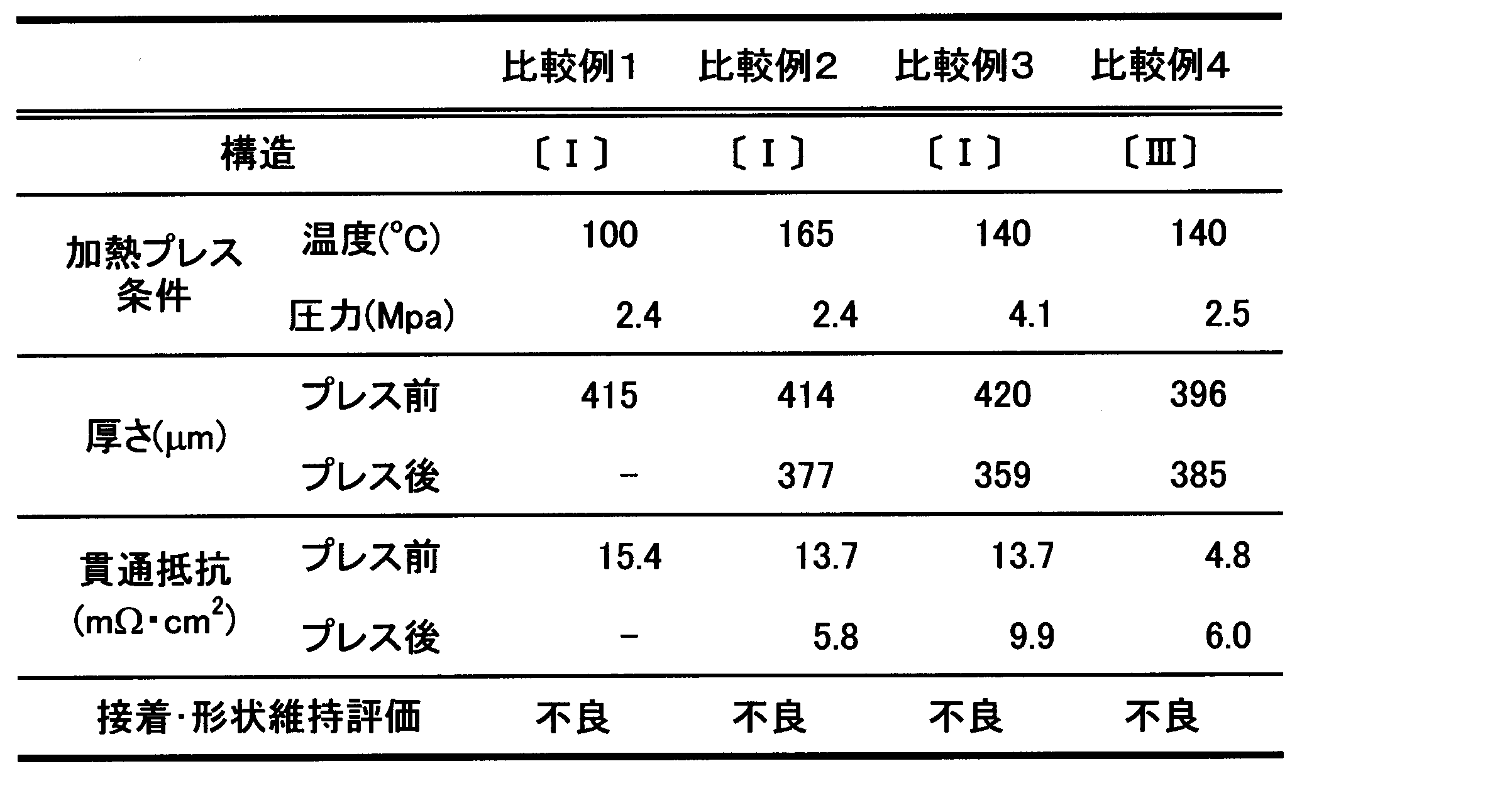
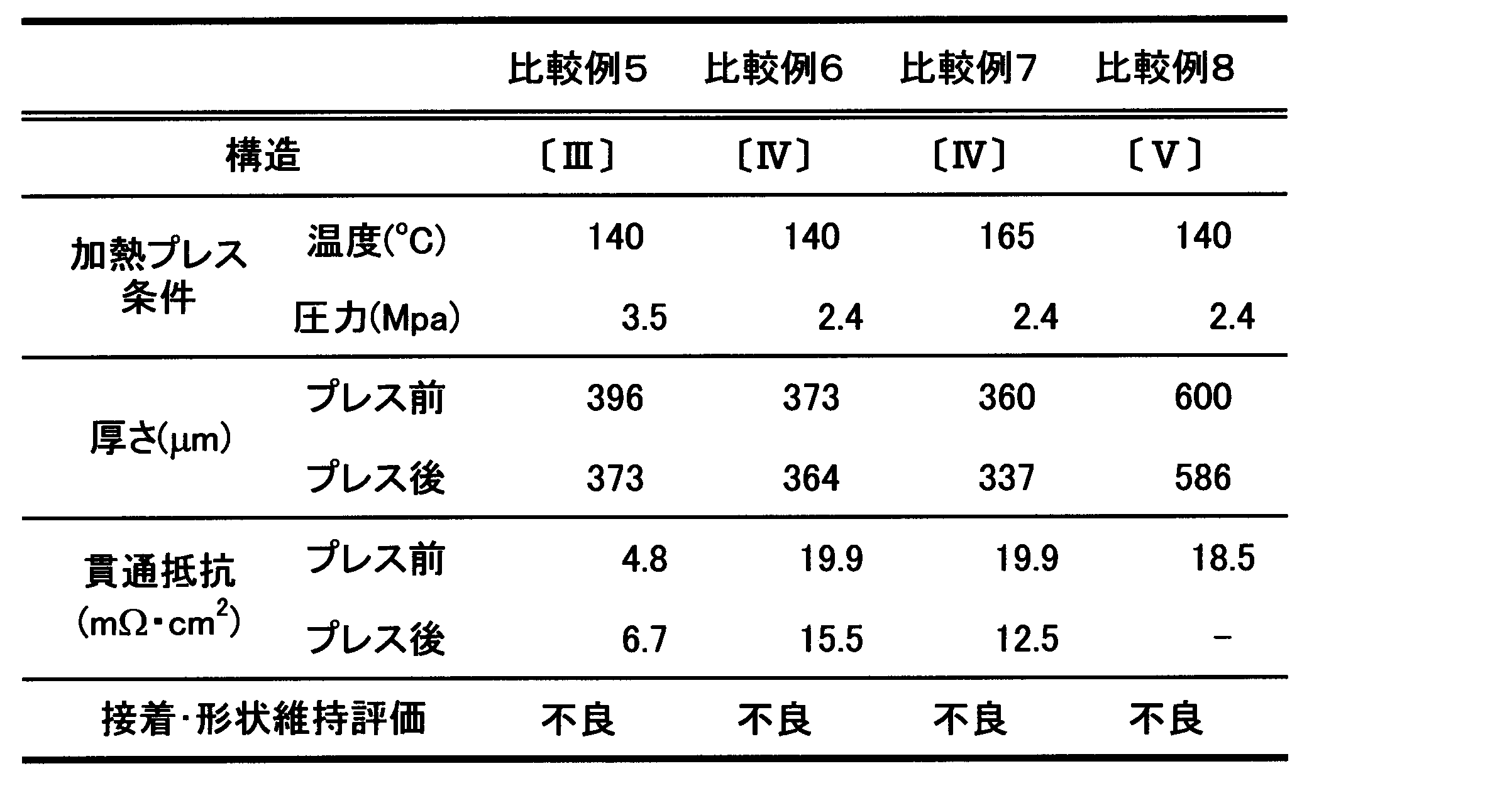
実施例の燃料電池用流路部材はいずれも良好な接着性評価を得ることができた。また、各部材の加熱プレスに伴う熱融着後においても貫通抵抗の値から導電性を確認した。加えて、金属板の種類を変更した実施例においても、良好な接着性評価を得ることができた。貫通抵抗の値の差異は金属板自体の抵抗と考えられる。比較例1は、加熱プレス時の温度が低く、樹脂の熱融着が十分に生じなかったため、接着不良となった。比較例2は、加熱プレス時の温度が高く、本来の流路となるべき溝付ベース部の樹脂も軟化して形状変形が生じてしまった。比較例3は、加熱プレス時の圧力が高く、形状変形が著しく不良となった。
2 カーボンナノチューブ
3 粒状黒鉛
4 炭素繊維
10A,10B,10C,10D,10E,10F 燃料電池用流路部材
11 第1導電部
13 ベース部
15,15d,15e,17,17d 溝部
16,16b,16c,16d,16e,16f,16g,16h,16x,16y 溝付ベース部
18 流体流路
19 条部
21 第2導電部
31 第3導電部
40 金属板
45 接着性樹脂層
50 金型
51 溝型面
Su 凹凸状溝部
Claims (11)
- 第1樹脂と炭素材料とを含有するシート状の第1導電部を得る工程と、
前記第1樹脂よりも低融点の第2樹脂と炭素材料とを含有するシート状の第2導電部を、前記第1導電部の少なくとも一面側に積層して、シート状のベース部を形成する工程と、
前記ベース部の表面に溝型面を転写して、溝部を設けた溝付ベース部を形成する工程と、
前記第1樹脂よりも低融点の第3樹脂と炭素材料とを含有するシート状の第3導電部を、前記溝付ベース部の前記溝部を形成した面側に積層する工程と、
前記溝付ベース部及び前記第3導電部の熱融着による一体化によって、前記溝部を被覆する工程とを備える
ことを特徴とする燃料電池用流路部材の製造方法。 - 前記溝付ベース部における前記第2導電部を積層した面側に前記溝部が設けられる請求項1に記載の燃料電池用流路部材の製造方法。
- 前記溝付ベース部の両面に前記溝部が設けられる請求項1に記載の燃料電池用流路部材の製造方法。
- 前記溝付ベース部における前記第2導電部を積層した面と逆側の面に前記溝部が設けられる請求項1に記載の燃料電池用流路部材の製造方法。
- 前記第3導電部に代えて他の前記溝付ベース部が、前記溝付ベース部の前記溝部を形成した面側に積層されている請求項1に記載の燃料電池用流路部材の製造方法。
- 前記溝部が凹凸状溝部である請求項1に記載の燃料電池用流路部材の製造方法。
- 前記凹凸状溝部が、溝部と条部との平行に連続した構造である請求項6に記載の燃料電池用流路部材の製造方法。
- 前記凹凸状溝部の溝深さが50~200μmであり、前記凹凸状溝部の溝幅が100~400μmである請求項6に記載の燃料電池用流路部材の製造方法。
- 前記溝付ベース部に金属板が備えられている請求項1に記載の燃料電池用流路部材の製造方法。
- 前記金属板に炭素材料を含有する接着性樹脂層が備えられる請求項9に記載の燃料電池用流路部材の製造方法。
- 前記炭素材料が、カーボンナノチューブ、粒状黒鉛、または炭素繊維の少なくとも1種以上である請求項1または10に記載の燃料電池用流路部材の製造方法。
Priority Applications (8)
| Application Number | Priority Date | Filing Date | Title |
|---|---|---|---|
| US15/521,443 US10431839B2 (en) | 2014-11-10 | 2015-11-02 | Method of production of channel member for fuel cell |
| KR1020177011088A KR102489281B1 (ko) | 2014-11-10 | 2015-11-02 | 연료전지용 유로 부재의 제조 방법 |
| PL15859373T PL3220465T3 (pl) | 2014-11-10 | 2015-11-02 | Sposób wytwarzania elementu drogi przepływu dla ogniwa paliwowego |
| CA2961141A CA2961141C (en) | 2014-11-10 | 2015-11-02 | Method of production of channel member for fuel cell |
| EP15859373.1A EP3220465B1 (en) | 2014-11-10 | 2015-11-02 | Method for manufacturing flow path member for fuel cell |
| CN201580061076.8A CN107112550B (zh) | 2014-11-10 | 2015-11-02 | 燃料电池用流路部件的制造方法 |
| US16/572,399 US11158875B2 (en) | 2014-11-10 | 2019-09-16 | Method of production of channel member for fuel cell |
| US16/572,544 US11158876B2 (en) | 2014-11-10 | 2019-09-16 | Method of production of channel member for fuel cell |
Applications Claiming Priority (4)
| Application Number | Priority Date | Filing Date | Title |
|---|---|---|---|
| JP2014227989 | 2014-11-10 | ||
| JP2014-227989 | 2014-11-10 | ||
| JP2015-209859 | 2015-10-26 | ||
| JP2015209859A JP6277169B2 (ja) | 2014-11-10 | 2015-10-26 | 燃料電池用流路部材の製造方法 |
Related Child Applications (3)
| Application Number | Title | Priority Date | Filing Date |
|---|---|---|---|
| US15/521,443 A-371-Of-International US10431839B2 (en) | 2014-11-10 | 2015-11-02 | Method of production of channel member for fuel cell |
| US16/572,544 Division US11158876B2 (en) | 2014-11-10 | 2019-09-16 | Method of production of channel member for fuel cell |
| US16/572,399 Division US11158875B2 (en) | 2014-11-10 | 2019-09-16 | Method of production of channel member for fuel cell |
Publications (1)
| Publication Number | Publication Date |
|---|---|
| WO2016076156A1 true WO2016076156A1 (ja) | 2016-05-19 |
Family
ID=55954247
Family Applications (1)
| Application Number | Title | Priority Date | Filing Date |
|---|---|---|---|
| PCT/JP2015/080932 Ceased WO2016076156A1 (ja) | 2014-11-10 | 2015-11-02 | 燃料電池用流路部材の製造方法 |
Country Status (1)
| Country | Link |
|---|---|
| WO (1) | WO2016076156A1 (ja) |
Citations (5)
| Publication number | Priority date | Publication date | Assignee | Title |
|---|---|---|---|---|
| JP2003217611A (ja) * | 2001-11-19 | 2003-07-31 | Ntn Corp | 燃料電池用セパレータおよび燃料電池 |
| JP2005209641A (ja) * | 2003-12-24 | 2005-08-04 | Showa Denko Kk | 燃料電池用セパレータ及びその製造方法 |
| JP2009093967A (ja) * | 2007-10-10 | 2009-04-30 | Nippon Pillar Packing Co Ltd | 燃料電池用セパレータ |
| JP2009176545A (ja) * | 2008-01-24 | 2009-08-06 | Toyota Motor Corp | 燃料電池の製造方法 |
| JP2011171111A (ja) * | 2010-02-18 | 2011-09-01 | Tokai Carbon Co Ltd | 燃料電池用セパレータの製造方法 |
-
2015
- 2015-11-02 WO PCT/JP2015/080932 patent/WO2016076156A1/ja not_active Ceased
Patent Citations (5)
| Publication number | Priority date | Publication date | Assignee | Title |
|---|---|---|---|---|
| JP2003217611A (ja) * | 2001-11-19 | 2003-07-31 | Ntn Corp | 燃料電池用セパレータおよび燃料電池 |
| JP2005209641A (ja) * | 2003-12-24 | 2005-08-04 | Showa Denko Kk | 燃料電池用セパレータ及びその製造方法 |
| JP2009093967A (ja) * | 2007-10-10 | 2009-04-30 | Nippon Pillar Packing Co Ltd | 燃料電池用セパレータ |
| JP2009176545A (ja) * | 2008-01-24 | 2009-08-06 | Toyota Motor Corp | 燃料電池の製造方法 |
| JP2011171111A (ja) * | 2010-02-18 | 2011-09-01 | Tokai Carbon Co Ltd | 燃料電池用セパレータの製造方法 |
Similar Documents
| Publication | Publication Date | Title |
|---|---|---|
| JP6277169B2 (ja) | 燃料電池用流路部材の製造方法 | |
| CN103597641B (zh) | 燃料电池用隔板的制造方法 | |
| US20170162878A1 (en) | Gas diffusion layer for fuel cell, fuel cell, and formation method for gas diffusion layer for fuel cell | |
| WO2014168081A1 (ja) | カーボン部材、カーボン部材の製造方法、レドックスフロー電池および燃料電池 | |
| US11367881B2 (en) | Method for manufacturing fuel cell and fuel cell | |
| CN102437301B (zh) | 用于聚合物电解质膜燃料电池的复合隔板及其制造方法 | |
| WO2004019438A1 (ja) | 燃料電池用セパレータ及びその製造方法 | |
| JP6639777B2 (ja) | Pefcセパレータ用カーボン複合材及びその製造方法 | |
| JP7725731B2 (ja) | 膜-電極-ユニットと、拡散層と、分配器プレートと、を備える電気化学セル、および電気化学セルを製造する方法 | |
| JP2019106344A (ja) | 燃料電池の製造方法 | |
| JP2014112475A (ja) | 燃料電池用セパレータの製造方法 | |
| JP2021114383A (ja) | 燃料電池セルおよび燃料電池セルの製造方法 | |
| JP4508574B2 (ja) | 燃料電池用セパレータ、燃料電池用セパレータの製造方法 | |
| JP2018181662A (ja) | 燃料電池 | |
| JP2009093938A (ja) | 燃料電池セパレータ | |
| JP2009224272A (ja) | 燃料電池 | |
| JP7735398B2 (ja) | 燃料電池用セパレータおよびその製造方法 | |
| JP2020068091A (ja) | レドックスフロー電池用双極板及びその製造方法 | |
| JP2022048654A (ja) | 燃料電池セルの製造方法 | |
| JP2017147160A (ja) | 膜電極ガス拡散層接合体 |
Legal Events
| Date | Code | Title | Description |
|---|---|---|---|
| 121 | Ep: the epo has been informed by wipo that ep was designated in this application |
Ref document number: 15859373 Country of ref document: EP Kind code of ref document: A1 |
|
| ENP | Entry into the national phase |
Ref document number: 2961141 Country of ref document: CA |
|
| REEP | Request for entry into the european phase |
Ref document number: 2015859373 Country of ref document: EP |
|
| WWE | Wipo information: entry into national phase |
Ref document number: 2015859373 Country of ref document: EP |
|
| ENP | Entry into the national phase |
Ref document number: 20177011088 Country of ref document: KR Kind code of ref document: A |
|
| WWE | Wipo information: entry into national phase |
Ref document number: 15521443 Country of ref document: US |
|
| NENP | Non-entry into the national phase |
Ref country code: DE |