WO2016076351A1 - Aérateur étanche à l'eau et appareil à dispositif électronique - Google Patents
Aérateur étanche à l'eau et appareil à dispositif électronique Download PDFInfo
- Publication number
- WO2016076351A1 WO2016076351A1 PCT/JP2015/081721 JP2015081721W WO2016076351A1 WO 2016076351 A1 WO2016076351 A1 WO 2016076351A1 JP 2015081721 W JP2015081721 W JP 2015081721W WO 2016076351 A1 WO2016076351 A1 WO 2016076351A1
- Authority
- WO
- WIPO (PCT)
- Prior art keywords
- hollow body
- opening
- waterproof ventilation
- ventilation device
- waterproof
- Prior art date
- Legal status (The legal status is an assumption and is not a legal conclusion. Google has not performed a legal analysis and makes no representation as to the accuracy of the status listed.)
- Ceased
Links
Images






Classifications
-
- H—ELECTRICITY
- H05—ELECTRIC TECHNIQUES NOT OTHERWISE PROVIDED FOR
- H05K—PRINTED CIRCUITS; CASINGS OR CONSTRUCTIONAL DETAILS OF ELECTRIC APPARATUS; MANUFACTURE OF ASSEMBLAGES OF ELECTRICAL COMPONENTS
- H05K5/00—Casings, cabinets or drawers for electric apparatus
- H05K5/02—Details
- H05K5/0213—Venting apertures; Constructional details thereof
- H05K5/0214—Venting apertures; Constructional details thereof with means preventing penetration of rain water or dust
-
- B—PERFORMING OPERATIONS; TRANSPORTING
- B01—PHYSICAL OR CHEMICAL PROCESSES OR APPARATUS IN GENERAL
- B01D—SEPARATION
- B01D53/00—Separation of gases or vapours; Recovering vapours of volatile solvents from gases; Chemical or biological purification of waste gases, e.g. engine exhaust gases, smoke, fumes, flue gases, aerosols
- B01D53/26—Drying gases or vapours
- B01D53/268—Drying gases or vapours by diffusion
Definitions
- the present invention relates to a waterproof ventilation device provided in a vent hole that communicates the inside and the outside of a housing of an electronic device device installed outdoors, and an electronic device device including the waterproof ventilation device.
- a water-repellent microporous member having a property of allowing air to pass through a wall but not allowing water to pass through as a waterproof ventilation structure provided in a ventilation hole that communicates the inside and outside of a housing of an electronic device installed outdoors
- a waterproof ventilation structure in which a labyrinth structure is provided so as to cover it referred to as a waterproof ventilation sheet
- Patent Document 1 has the following problems. In some cases, water stays in the opening or inside of the labyrinth structure and closes the air flow path. In this state, if the inside of the housing becomes a negative pressure (a state in which the internal pressure is smaller than the external pressure), water may be sucked over the waterproof ventilation sheet. When a strong jet hits directly from below or diagonally below, water hits the waterproof breathable sheet directly. The waterproof breathable sheet deteriorates due to various environmental loads, and the waterproofness or breathability is impaired.
- the present invention has been made in order to solve the above-described problems, and has a predetermined waterproof performance, and the inside of a housing in which the waterproof vent is attached after the waterproof vent is exposed to water.
- the object is to prevent water from entering the housing even when air enters the housing.
- the waterproof ventilation device includes an outer hollow body and an inner hollow body.
- the outer hollow body has a space inside, and has an outer opening at a lower side surface where a water film is not stretched.
- the inner hollow body has a space inside, and at least a part thereof is accommodated in the outer hollow body.
- the outer surface of the inner hollow body is arranged so that a water film does not stretch between the inner surface of the outer hollow body.
- the inner hollow body has an inner opening and an upper opening.
- the inner opening is provided so that the water film does not stretch at a position where the water that has entered the outer hollow body through the outer opening does not directly hit.
- the upper opening is provided above the inner opening and communicates with the outside of the outer hollow body.
- the housing has the determined waterproof performance, and even when air enters the inside of the housing to which the waterproof ventilation device is attached after the waterproof ventilation device is exposed to water, Water can be prevented from entering inside.
- FIG. 1 is a perspective view of a waterproof ventilation device according to Embodiment 1.
- FIG. 1 is a plan view of a waterproof ventilation device according to Embodiment 1.
- FIG. 5 is a vertical sectional view of the waterproof ventilation device according to Embodiment 1 taken along line BB shown in FIG. 5 is a vertical sectional view taken along the line CC shown in FIG. 4 of the waterproof ventilation device according to Embodiment 1.
- FIG. FIG. 6 is a horizontal sectional view taken along the line DD shown in FIG. 5 of the waterproof ventilation device according to Embodiment 1.
- FIG. 6 is a horizontal sectional view taken along line EE shown in FIG. 5 of the waterproof ventilation device according to Embodiment 1.
- FIG. 7 is a vertical sectional view taken along the line FF shown in FIG. 6 for illustrating the structure of the waterproof ventilation device according to the first embodiment.
- FIG. 6 is a vertical sectional view taken along the line GG shown in FIG. 5 for describing the structure of the waterproof ventilation device according to the first embodiment.
- FIG. 7 is a perspective view of the waterproof ventilation device taken along the line FF shown in FIG. 6 for illustrating the structure of the waterproof ventilation device according to Embodiment 1.
- FIG. 6 is a perspective view of the waterproof ventilation device taken along the line GG shown in FIG. 5 for describing the structure of the waterproof ventilation device according to Embodiment 1.
- FIG. 3 is a perspective view of the waterproof ventilation device with a part broken on the upper side for explaining the structure of the waterproof ventilation device according to Embodiment 1; It is a perspective view of the double cylinder member which fractured
- FIGS. 1 is a cross-sectional view of an electronic device apparatus having a waterproof ventilation device according to Embodiment 1 of the present invention.
- FIG. 2 is a plan view of the electronic apparatus device having the waterproof ventilation device according to Embodiment 1 as viewed from below.
- FIG. 1 is a cross-sectional view taken along line AA shown in FIG. 2, which is a position passing through the waterproof ventilation device.
- An electronic device 1 (not shown) that is a device that uses electricity is accommodated in a housing 2.
- a vent hole 3 is provided on the bottom surface of the housing 2.
- a waterproof ventilation tool 4 is attached below the ventilation hole 3.
- the waterproof ventilation device 4 allows air to communicate between the ventilation hole 3 and the outside of the housing 2.
- the waterproof ventilation device 4 is waterproofed so that water does not enter the inside of the housing 2 from the ventilation hole 3.
- the waterproof ventilation device 4 is attached to the housing 2 by an appropriate method such as adhesive or screwing.
- FIG. 3 is a perspective view of the waterproof ventilation device according to the first embodiment.
- 4 is a plan view of the waterproof ventilation device according to Embodiment 1.
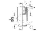
- FIG. FIG. 5 is a vertical sectional view of the waterproof ventilation device according to Embodiment 1 taken along the line BB shown in FIG. 6 is a vertical sectional view taken along the line CC of FIG. 4 of the waterproof ventilation device according to the first embodiment.
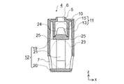
- FIG. 7 is a horizontal sectional view taken along the line DD shown in FIG. 5 of the waterproof ventilation device according to the first embodiment.
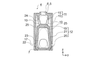
- 8 is a horizontal sectional view of the waterproof ventilation device according to Embodiment 1 taken along the line EE shown in FIG. FIG.
- FIG. 9 is a vertical sectional view taken along the line FF shown in FIG. 6 for explaining the structure of the waterproof ventilation device according to the first embodiment.
- FIG. 10 is a vertical sectional view taken along the line GG shown in FIG. 5 for explaining the structure of the waterproof ventilation device according to the first embodiment.
- FIG. 11 is a perspective view of the waterproof ventilation device taken along the line FF shown in FIG. 6 for explaining the structure of the waterproof ventilation device according to the first embodiment.
- 12 is a perspective view of the waterproof ventilation device taken along the line GG shown in FIG. 5 for describing the structure of the waterproof ventilation device according to Embodiment 1.
- FIG. FIG. 13 is a perspective view of the waterproof ventilation device with a part of the upper side broken to explain the structure of the waterproof ventilation device according to the first embodiment.
- FIG. 14 is a perspective view of a double-cylinder member in which a part of the upper side is broken for explaining the structure of the double-cylinder member included in the waterproof ventilation device according to the first embodiment.
- FIG. 15 is a perspective view of the bottom member of the waterproof ventilation device according to the first embodiment.
- the waterproof ventilation device 4 is a cylinder having an upper bottom and a lower bottom, and has a height of about 3 cm and a diameter of about 2 cm.
- a boss 5 having an outer diameter substantially the same as the inner diameter of the vent hole 3 and a housing side hole 6 provided in the boss 5 are provided.
- At the lower part of the side surface there are two outer openings 7 provided so as to face each other.
- the shape of the outer opening 7 is a trapezoid whose upper corner is rounded.
- the side surface, bottom surface and top surface where the outer opening 7 is provided constitute an outer hollow body 8 having a space inside.
- the boss 5 is attached to the housing 2 with the upper part of the boss 5 inside the vent hole 3.
- the housing side hole 6 is an upper opening communicating with the vent hole 3.
- the z-axis is a direction perpendicular to the upper surface of the waterproof ventilation device 4, that is, a height direction.
- the x axis and the y axis exist in a plane parallel to the upper surface.
- the x-axis is the direction in which the two outer openings 7 face each other, that is, the direction parallel to the straight line connecting the centers of the two outer openings 7.
- the y-axis is a direction perpendicular to the x-axis and the z-axis.
- the waterproof ventilation device 4 has a shape symmetrical with respect to the z axis in the xz plane and the yz plane.
- FIG. 4 shows the position of a vertical section that is a plane including the z-axis for explaining the structure of the waterproof ventilation device 4.
- the BB cross section is a cross section in which the right half in the drawing of the waterproof ventilation device 4 is a cross section parallel to the xz plane and the left half is a view seen from the side.
- the CC cross section is a cross section in which the right half in the drawing of the waterproof ventilation device 4 is a cross section parallel to the yz plane, and the left half is viewed from the side.
- FIG. 5 shows the position of the horizontal cross section which is a plane parallel to the xy plane for explaining the structure of the waterproof ventilation device 4.
- the DD cross section is a horizontal cross section at a portion where the inner hollow body 9 exists.
- the EE cross section is a horizontal cross section below the inner hollow body 9.
- the waterproof ventilation device 4 has a structure having an inner hollow body 9 that is another hollow body in the upper part of the internal space of the cylindrical outer hollow body 8.
- the inner hollow body 9 has a cylindrical shape having an upper bottom and a lower bottom.
- Two inner openings 10 facing each other are also provided in the lower portion of the inner hollow body 9.
- a direction in which the two inner openings 10 face each other, that is, a straight line connecting the centers of the two inner openings 10 is parallel to the y axis.
- the shape of the inner opening 10 is a trapezoid with rounded corners.
- the waterproof ventilation device 4 includes a double cylinder member 11 having a double cylinder and a double cylinder member 11 that are arranged so that the central axes with the upper base in common and the lower base open are in the same position.
- the bottom member 12 blocks the lower bottom of the two cylinders.
- two trapezoidal notches 14 are provided on the lower bottom side, that is, the lower end of the outer cylinder 13 of the double cylinder member 11 at positions facing each other.
- the length of the inner cylinder 15 is about 30% of that of the outer cylinder 13.
- Two trapezoidal cutouts 16 are also provided on the lower bottom side, that is, the lower end of the inner cylinder 15 at positions facing each other.
- a straight line connecting the centers of the two notches 14 of the outer cylinder 13 and a straight line connecting the centers of the two notches 16 of the inner cylinder 15 are orthogonal to each other. Strictly speaking, these two straight lines are not on the same plane and are in a twisted position.
- the term “orthogonal” in this specification also means a case where two straight lines are orthogonal to each other in a state where either straight line is translated and the two straight lines exist on the same plane.
- the notch 14 of the outer cylinder 13 is provided so that the outer opening 7 can be formed between the bottom of the outer cylinder 13 of the bottom member 12.
- the notch 16 of the inner cylinder 15 is also provided so that the inner opening 10 can be formed between the bottom of the inner cylinder 15 of the bottom member 12.
- the outer opening 7 is provided in contact with the bottom of the outer hollow body 8
- the water that has entered the outer hollow body 8 is discharged from the outer opening 7 by gravity.
- the inner opening 10 is provided in contact with the bottom of the inner hollow body 9, the water that has entered the inner hollow body 9 is discharged from the inner opening 10 by gravity.
- Two claw storage holes 17 that are used to integrate the double cylinder member 11 and the bottom member 12 are provided at opposing positions at the bottom of the outer cylinder 13.
- the cross-sectional shapes of the two claw storage holes 17 are the same, and are rectangular with rounded corners.
- the two claw storage holes 17 are located at the same height from the lower end of the outer cylinder 13.
- the bottom member 12 includes an inner bottom 19 having a circular protrusion 18 that fits with the inner cylinder 15, an outer bottom 20 that covers the opened lower bottom of the outer cylinder 13, and an inner bottom 19. It has two legs 21 which are connecting parts connecting the outer bottom 20.
- Each of the two legs 21 is provided with a claw 22 having a half width of the leg 21 at the same height at the lower part on the outside.
- the double cylinder member 11 and the bottom member 12 are integrated with each other by the claws 22 of the legs 21 entering and fitting into the claw storage holes 17 of the outer cylinder 13.
- the outer cylinder 13 and the outer bottom 20 constitute the outer hollow body 8.
- the inner hollow body 9 is constituted by the inner cylinder 15 and the inner bottom 19.
- the positions of the claw 22 and the claw storage hole 17 are positions where the lower end of the outer bottom 20 coincides with the lower end of the outer cylinder 13 in a state where the claw 22 enters the claw storage hole 17. As shown in FIG.
- the cross-sectional shape of the claw 22 in a plane that passes through the center of the bottom member 12 and includes the z-axis is a fan shape in which the central angle is 90 degrees with a straight line on the lower side and an arc on the upper side.
- the inner space of the outer hollow body 8 is roughly divided into three, as indicated by the dashed ellipse.
- the first is a lower space 23 which is a space below the inner hollow body 9.
- the second is an upper space 24 which is a space inside the inner hollow body 9.
- the third is a communication space 25 that is above the bottom of the inner hollow body 9 and is outside the inner hollow body 9.
- the lower space 23 and the communication space 25 communicate with each other inside the portion where the outer opening 7 of the outer cylinder 13 is provided.
- the lower space 23 and the communication space 25 do not communicate with each other in this portion.
- the communication space 25 and the upper space 24 communicate with each other through the inner opening 10.
- the communication space 25 and the upper space 24 do not communicate with each other in the portion of the inner cylinder 15 where the inner opening 10 is not provided.
- FIG. H1 Height of the lower space 23
- H2 Height of the outer opening 7
- H3 Height of the upper space 24
- H4 Height of the inner opening 10
- W Distance between the inner surface of the outer cylinder 13 and the outer surface of the inner cylinder 15
- the shape and size of the outer opening 7 and the inner opening 10 are determined so that the water film does not stretch due to surface tension.
- the distance W between the inner surface of the outer cylinder 13 and the outer surface of the inner cylinder 15 is also made sufficiently large according to the shape so as not to stretch.
- H1 / H2> 2 and H3 / H4> 1.5 is given.
- H1 / H2 is increased with respect to the same H2
- the probability that water entering the lower space 23 from the outer opening 7 reaches the inner opening 10 can be reduced.
- H3 / H4 is increased with respect to the same H4
- the probability that water entering the upper space 24 from the inner opening 10 reaches the housing side hole 6 can be reduced.
- H1 / H2 is the same, the probability that the water that has entered the lower space 23 will reach the inner opening 10 decreases as H1 increases.
- H3 / H4 is the same, the probability that the water that has entered the upper space 24 reaches the housing side hole 6 is smaller as H3 is larger.
- the dimensions of each part of the waterproof ventilation device should be determined appropriately according to the amount of ventilation to be secured and the restrictions on the space where it can be installed.
- the waterproof ventilation device 4 satisfies the protection class 6 (IPX6) of the JIS standard “Protection class by outer shell of electric machine (JIS C 0920)”.
- IPX6 the protection class 6
- the waterproof ventilation device 4 has the following three structures for waterproofing.
- a structure of a rapidly expanding pipe that makes the cross-sectional area of the internal space larger than the cross-sectional area of the outer opening 7.
- B A labyrinth structure that bends the path from the outer opening 7 to the housing side hole 6 many times.
- C A structure in which a water film is not stretched due to surface tension in the opening and inside.
- the two outer openings 7 and the lower space 23 can be viewed as pipes in the x-axis direction.
- the flow of water flowing from the outside to the inside of the waterproof ventilation device 4 is considered to be mainly in the x-axis direction.
- the flow of water flowing in the x-axis direction is disturbed at a sudden expansion portion immediately after entering from the outer opening 7 to cause a loss. Therefore, there is an effect of reducing the amount of water that goes above the outer opening 7.
- the two outer openings 7 face each other, the flow of water flowing from the outside flows down from the outer opening 7 opposite to the outer opening 7 into which most of the water flows.
- any one of the outer openings 7 has a ventilation performance due to continuously flowing water or foreign matter. Even in the case of loss of air, the other outer opening 7 can ensure ventilation.
- the water that tends to move upward inside the inner hollow body 9 and then falls due to gravity or the like has a structure that easily flows out of the waterproof ventilator 4.
- the effective cross-sectional area of the outer opening 7 becomes small, and water does not easily enter the waterproof ventilation device 4.
- the cross-sectional area gradually increases, but the degree of expansion of the cross-sectional area also increases. Therefore, it seems that the effect of reducing the momentum of the water flow is not greatly reduced compared to the case of the x-axis direction.
- FIG. 16 is a cross-sectional view illustrating a path from the outer opening of the waterproof ventilation device according to Embodiment 1 to the housing side hole on the upper surface. Since the legs 21 exist below the inner opening 10 in the radial direction, the legs 21 cannot move directly from the lower space 23 to the communication space 25 radially outside the inner opening 10. As shown in FIG. 16 (A), the path 26 from the outer opening 7 to the housing side hole 6 on the upper surface is on the upper side until the position immediately after entering the outer opening 7 or the position immediately before leaving the other outer opening 7. The direction is changed to enter the communication space 25 from the lower space 23. As shown in FIG.
- the path 26 enters the upper space 24 from the inner opening 10 by making a quarter turn between the outer cylinder 13 and the inner cylinder 15 toward the inner opening 10. As shown in FIG. 16C, the path 26 changes its direction upward in the upper space 24 and reaches the housing side hole 6. Thus, in order to reach from the outer opening 7 to the housing side hole 6 on the upper surface, it is necessary to change the direction at an angle close to a right angle at least four times. This route is a route that goes up against gravity.
- the inner opening 10 cannot be seen from the outer opening 7.
- the inner opening 10 is provided at a position where water that has entered the outer hollow body 8 through the outer opening 7 does not directly hit. Since the legs 21 exist just below the radial direction of the inner opening 10, the fluid entering the inner opening 10 mainly moves in the horizontal direction in the communication space 25. This means that the leg 21 functions as a flow path restricting portion that prevents the leg 21 from entering from below the inner opening 10. You may make it attach the member for restrict
- the fluid (water or air containing water) that has entered the inside of the waterproof ventilation device 4 from the outer opening 7 hits the inner wall surface of the waterproof ventilation device 4 many times inside the waterproof ventilation device 4 and weakens the momentum. It is done.
- the communication space 25 having a small cross-sectional area there is a path having a relatively large cross-sectional area called the lower space 23. Therefore, the increase in the cross-sectional area reduces the momentum of the fluid, and the amount of water entering the communication space 25 is as follows. Get smaller. Further, since the momentum is weakened, most of the water that has entered the communication space 25 falls toward the lower space 23 due to gravity.
- the water that has entered the inner hollow body 9 from one inner opening 10 flows out from the other inner opening 10.
- the water reflected from the inner surface of the inner hollow body 9 decreases in momentum and falls to the bottom surface and flows out from the inner opening 10.
- the shape and size of the opening and the shape and spacing of the connecting space are determined in consideration of the hydrophilicity of the waterproof ventilation material. In the case of a material having water repellency, it is determined so that a water film does not occur even if the water repellency decreases due to deterioration over time.
- Waterproof ventilator 4 is attached to the ventilation holes of the outdoor installation casing whose vertical and horizontal dimensions are about 350 mm, and is protected according to the JIS standard “Electrical equipment enclosure protection grade (JIS C 0920)”. A waterproof test specified in grade 6 (IPX6) was performed. As a result, it has been confirmed that there is no water intrusion inside the case for outdoor installation and the IPX6 standard is satisfied.
- JIS C 0920 Electrical equipment enclosure protection grade
- IPX6 grade 6
- the waterproof ventilation device 4 is composed of two members, a double cylinder member 11 and a bottom member 12, and can be easily assembled. Since the disk-shaped protrusion 18 fitted to the inner surface of the inner cylinder 19 is provided on the upper surface of the bottom member 12, when the bottom member 12 is assembled to the double cylinder member 11, Suppresses misalignment. Further, the bottom member 19 is held at the center of the inner cylinder 15 by the disk-shaped protrusion 18, and the looseness of fitting by the claw 21 and the through hole 17 is suppressed. Thus, the flow path of the waterproof ventilation device can be maintained in a desired size and shape without using an additional adhesive member or the like.
- the outer shape of the waterproof ventilation device is a cylindrical shape, but it may be a rectangular tube shape, a truncated cone shape, a truncated pyramid shape, a polyhedral shape, an oval shape, or the like.
- the upper bottom of the outer hollow body and the upper bottom of the inner hollow body are made common, the upper portion of the inner hollow body may protrude from the outer hollow body.
- the waterproof ventilation device may have any shape.
- the member on the side having the upper opening communicating with the ventilation hole of the housing may be formed integrally with the housing.
- the opening of the hollow body into one is advantageous in that one opening can be enlarged and the opening has a size that does not stretch the water film.
- the outer openings are two openings having the same shape and size, the shape and size of the water film is not stretched even on the small side, and either or both of the shapes and sizes of the openings may be different. Good.
- the shape and size of the opening may be different from each other after the shape and size of the water film are not stretched even on the smaller side.
- any opening can have the same waterproof performance.
- a standard different from JIS may be used.
- the present invention can be applied to JIS standards and standards that are stricter or more lenient than protection class 6 (IPX6).
- IPX6 protection class 6
- the present invention can be applied even when the waterproof performance determined independently of the standard is satisfied.
- the invention of the present application can be modified or omitted within the spirit of the invention.
Landscapes
- Engineering & Computer Science (AREA)
- Chemical & Material Sciences (AREA)
- Microelectronics & Electronic Packaging (AREA)
- Analytical Chemistry (AREA)
- General Chemical & Material Sciences (AREA)
- Oil, Petroleum & Natural Gas (AREA)
- Chemical Kinetics & Catalysis (AREA)
- Casings For Electric Apparatus (AREA)
- Cooling Or The Like Of Electrical Apparatus (AREA)
Abstract
Priority Applications (3)
| Application Number | Priority Date | Filing Date | Title |
|---|---|---|---|
| JP2016529483A JP5991454B1 (ja) | 2014-11-14 | 2015-11-11 | 防水通気具および電子機器装置 |
| US15/516,771 US9949388B2 (en) | 2014-11-14 | 2015-11-11 | Waterproof ventilator and electronic device apparatus |
| CN201580056582.8A CN107148810B (zh) | 2014-11-14 | 2015-11-11 | 防水通气件及电子设备装置 |
Applications Claiming Priority (2)
| Application Number | Priority Date | Filing Date | Title |
|---|---|---|---|
| JP2014-231217 | 2014-11-14 | ||
| JP2014231217 | 2014-11-14 |
Publications (1)
| Publication Number | Publication Date |
|---|---|
| WO2016076351A1 true WO2016076351A1 (fr) | 2016-05-19 |
Family
ID=55954430
Family Applications (1)
| Application Number | Title | Priority Date | Filing Date |
|---|---|---|---|
| PCT/JP2015/081721 Ceased WO2016076351A1 (fr) | 2014-11-14 | 2015-11-11 | Aérateur étanche à l'eau et appareil à dispositif électronique |
Country Status (4)
| Country | Link |
|---|---|
| US (1) | US9949388B2 (fr) |
| JP (1) | JP5991454B1 (fr) |
| CN (1) | CN107148810B (fr) |
| WO (1) | WO2016076351A1 (fr) |
Cited By (1)
| Publication number | Priority date | Publication date | Assignee | Title |
|---|---|---|---|---|
| JP2019021717A (ja) * | 2017-07-14 | 2019-02-07 | 信越ポリマー株式会社 | 基板収納容器 |
Families Citing this family (5)
| Publication number | Priority date | Publication date | Assignee | Title |
|---|---|---|---|---|
| US10165694B1 (en) | 2017-09-11 | 2018-12-25 | Apple Inc. | Concealed barometric vent for an electronic device |
| CN108263578B (zh) * | 2018-02-05 | 2024-03-26 | 深圳市兰美蓝科技有限公司 | 一体式浮潜面罩及其呼吸管和通气件 |
| US11614716B2 (en) | 2019-09-23 | 2023-03-28 | Apple Inc. | Pressure-sensing system for a wearable electronic device |
| KR102870067B1 (ko) * | 2019-12-20 | 2025-10-16 | 삼성전자주식회사 | 통기 및 방수 구조를 포함하는 웨어러블 전자 장치 |
| US11860585B2 (en) | 2020-06-17 | 2024-01-02 | Apple Inc. | Wearable electronic device with a compressible air-permeable seal |
Citations (3)
| Publication number | Priority date | Publication date | Assignee | Title |
|---|---|---|---|---|
| JPS6421906U (fr) * | 1987-07-31 | 1989-02-03 | ||
| JPH062112Y2 (ja) * | 1988-07-13 | 1994-01-19 | 東京瓦斯株式会社 | ガスメータ用通気口 |
| JP2010175057A (ja) * | 2009-02-02 | 2010-08-12 | Japan Radio Co Ltd | 給排装置 |
Family Cites Families (14)
| Publication number | Priority date | Publication date | Assignee | Title |
|---|---|---|---|---|
| US4086394A (en) * | 1976-09-23 | 1978-04-25 | Elpower Corporation | Combination of a battery and vent structure |
| JPH0547490Y2 (fr) * | 1987-09-30 | 1993-12-14 | ||
| FR2687456B1 (fr) * | 1992-02-17 | 1999-04-02 | Valeo Vision | Projecteur equipe de moyens de ventilation perfectionnes, notamment pour vehicule automobile. |
| JP4043674B2 (ja) * | 1999-11-18 | 2008-02-06 | 日東電工株式会社 | 通気キャップおよびそれを用いた屋外用ランプ,自動車用ランプならびに自動車用電装部品 |
| US6883948B2 (en) * | 2002-01-17 | 2005-04-26 | Guide Corporation | Automotive lamp assembly moisture control system |
| WO2004023130A1 (fr) * | 2002-08-27 | 2004-03-18 | Ngk Spark Plug Co., Ltd. | Détecteur de gaz |
| ITTO20030169U1 (it) * | 2003-11-04 | 2005-05-05 | Gate Srl | Dispositivo valvolare di sfiato per un contenitore di un'unita' elettr onica di controllo. |
| DE102007012703A1 (de) * | 2006-12-22 | 2008-06-26 | Robert Bosch Gmbh | Druckausgleichselement für ein Gehäuse und Kraftfahrzeug-Elektrokomponente mit einem solchen Druckausgleichselement |
| US8430114B2 (en) * | 2009-09-08 | 2013-04-30 | GM Global Technology Operations LLC | Hydrophobic vent assembly |
| US8454719B2 (en) * | 2010-01-15 | 2013-06-04 | GM Global Technology Operations LLC | Transmission breather assembly |
| CN202103996U (zh) * | 2011-05-30 | 2012-01-04 | 张春林 | 一种防水透气帽 |
| CN202145715U (zh) * | 2011-07-27 | 2012-02-15 | 常州市泛亚微透科技有限公司 | 一种保护性卡扣式防水透气栓 |
| CN202941056U (zh) * | 2012-11-15 | 2013-05-15 | 勖连科技股份有限公司 | 防水透气钮结构 |
| JP2014120579A (ja) | 2012-12-14 | 2014-06-30 | Denso Corp | 防水構造 |
-
2015
- 2015-11-11 JP JP2016529483A patent/JP5991454B1/ja not_active Expired - Fee Related
- 2015-11-11 US US15/516,771 patent/US9949388B2/en not_active Expired - Fee Related
- 2015-11-11 WO PCT/JP2015/081721 patent/WO2016076351A1/fr not_active Ceased
- 2015-11-11 CN CN201580056582.8A patent/CN107148810B/zh not_active Expired - Fee Related
Patent Citations (3)
| Publication number | Priority date | Publication date | Assignee | Title |
|---|---|---|---|---|
| JPS6421906U (fr) * | 1987-07-31 | 1989-02-03 | ||
| JPH062112Y2 (ja) * | 1988-07-13 | 1994-01-19 | 東京瓦斯株式会社 | ガスメータ用通気口 |
| JP2010175057A (ja) * | 2009-02-02 | 2010-08-12 | Japan Radio Co Ltd | 給排装置 |
Cited By (1)
| Publication number | Priority date | Publication date | Assignee | Title |
|---|---|---|---|---|
| JP2019021717A (ja) * | 2017-07-14 | 2019-02-07 | 信越ポリマー株式会社 | 基板収納容器 |
Also Published As
| Publication number | Publication date |
|---|---|
| US20170303409A1 (en) | 2017-10-19 |
| CN107148810A (zh) | 2017-09-08 |
| US9949388B2 (en) | 2018-04-17 |
| JPWO2016076351A1 (ja) | 2017-04-27 |
| JP5991454B1 (ja) | 2016-09-14 |
| CN107148810B (zh) | 2019-11-01 |
Similar Documents
| Publication | Publication Date | Title |
|---|---|---|
| JP5991454B1 (ja) | 防水通気具および電子機器装置 | |
| JP4560477B2 (ja) | 電子制御装置および防水ケース | |
| CN103313560B (zh) | 用于收容电气设备的防爆安全壳 | |
| US8854816B2 (en) | Water-proof cover for an inverter unit | |
| CN103596391B (zh) | 电源适配器壳体组件、电源适配器、空调器及除湿机 | |
| JP6072947B1 (ja) | 防水型制御装置 | |
| KR101368616B1 (ko) | 냉동장치의 실외유닛 | |
| JP2014164825A (ja) | コネクタ | |
| JP4443386B2 (ja) | 電子制御機器 | |
| JP2017139057A (ja) | 防水型制御装置 | |
| US20160105995A1 (en) | Cooling air system and splash-water protection arrangement for a cooling air system of a housing | |
| WO2017149752A1 (fr) | Dispositif d'extérieur de climatiseur | |
| KR20140011408A (ko) | 냉동장치의 실외유닛 | |
| JP2014209639A (ja) | 電子制御装置 | |
| JP5587849B2 (ja) | 筐体 | |
| CN105658026B (zh) | 一种电子终端 | |
| JP2009510596A (ja) | 携帯型電子装置の通気 | |
| CN113015358B (zh) | 外壳及具有所述外壳的户外设备 | |
| JP2022040632A (ja) | 電子装置 | |
| CN205213200U (zh) | 一种具有通风口的壳体及仪表 | |
| JP5836118B2 (ja) | 電子機器筐体の通気構造 | |
| KR20140003210U (ko) | 선박의 환기 장치 | |
| CN107085455A (zh) | 用于计算机的保护外壳和用于制造此种外壳的方法 | |
| CN104703420A (zh) | 透气装置和带有透气装置的设备 | |
| CN204810763U (zh) | 一种防水防尘结构及具有该防水防尘结构的仪表 |
Legal Events
| Date | Code | Title | Description |
|---|---|---|---|
| ENP | Entry into the national phase |
Ref document number: 2016529483 Country of ref document: JP Kind code of ref document: A |
|
| 121 | Ep: the epo has been informed by wipo that ep was designated in this application |
Ref document number: 15859749 Country of ref document: EP Kind code of ref document: A1 |
|
| WWE | Wipo information: entry into national phase |
Ref document number: 15516771 Country of ref document: US |
|
| NENP | Non-entry into the national phase |
Ref country code: DE |
|
| 122 | Ep: pct application non-entry in european phase |
Ref document number: 15859749 Country of ref document: EP Kind code of ref document: A1 |