WO2016080030A1 - 高粘性液体用二重容器 - Google Patents
高粘性液体用二重容器 Download PDFInfo
- Publication number
- WO2016080030A1 WO2016080030A1 PCT/JP2015/073079 JP2015073079W WO2016080030A1 WO 2016080030 A1 WO2016080030 A1 WO 2016080030A1 JP 2015073079 W JP2015073079 W JP 2015073079W WO 2016080030 A1 WO2016080030 A1 WO 2016080030A1
- Authority
- WO
- WIPO (PCT)
- Prior art keywords
- container
- outer layer
- contents
- double
- liquid
- Prior art date
- Legal status (The legal status is an assumption and is not a legal conclusion. Google has not performed a legal analysis and makes no representation as to the accuracy of the status listed.)
- Ceased
Links
Images




Classifications
-
- B—PERFORMING OPERATIONS; TRANSPORTING
- B65—CONVEYING; PACKING; STORING; HANDLING THIN OR FILAMENTARY MATERIAL
- B65D—CONTAINERS FOR STORAGE OR TRANSPORT OF ARTICLES OR MATERIALS, e.g. BAGS, BARRELS, BOTTLES, BOXES, CANS, CARTONS, CRATES, DRUMS, JARS, TANKS, HOPPERS, FORWARDING CONTAINERS; ACCESSORIES, CLOSURES, OR FITTINGS THEREFOR; PACKAGING ELEMENTS; PACKAGES
- B65D35/00—Pliable tubular containers adapted to be permanently or temporarily deformed to expel contents, e.g. collapsible tubes for toothpaste or other plastic or semi-liquid material; Holders therefor
- B65D35/22—Pliable tubular containers adapted to be permanently or temporarily deformed to expel contents, e.g. collapsible tubes for toothpaste or other plastic or semi-liquid material; Holders therefor with two or more compartments
-
- B—PERFORMING OPERATIONS; TRANSPORTING
- B65—CONVEYING; PACKING; STORING; HANDLING THIN OR FILAMENTARY MATERIAL
- B65D—CONTAINERS FOR STORAGE OR TRANSPORT OF ARTICLES OR MATERIALS, e.g. BAGS, BARRELS, BOTTLES, BOXES, CANS, CARTONS, CRATES, DRUMS, JARS, TANKS, HOPPERS, FORWARDING CONTAINERS; ACCESSORIES, CLOSURES, OR FITTINGS THEREFOR; PACKAGING ELEMENTS; PACKAGES
- B65D35/00—Pliable tubular containers adapted to be permanently or temporarily deformed to expel contents, e.g. collapsible tubes for toothpaste or other plastic or semi-liquid material; Holders therefor
- B65D35/14—Pliable tubular containers adapted to be permanently or temporarily deformed to expel contents, e.g. collapsible tubes for toothpaste or other plastic or semi-liquid material; Holders therefor with linings or inserts
-
- B—PERFORMING OPERATIONS; TRANSPORTING
- B65—CONVEYING; PACKING; STORING; HANDLING THIN OR FILAMENTARY MATERIAL
- B65D—CONTAINERS FOR STORAGE OR TRANSPORT OF ARTICLES OR MATERIALS, e.g. BAGS, BARRELS, BOTTLES, BOXES, CANS, CARTONS, CRATES, DRUMS, JARS, TANKS, HOPPERS, FORWARDING CONTAINERS; ACCESSORIES, CLOSURES, OR FITTINGS THEREFOR; PACKAGING ELEMENTS; PACKAGES
- B65D23/00—Details of bottles or jars not otherwise provided for
- B65D23/001—Supporting means fixed to the container
-
- A—HUMAN NECESSITIES
- A23—FOODS OR FOODSTUFFS; TREATMENT THEREOF, NOT COVERED BY OTHER CLASSES
- A23L—FOODS, FOODSTUFFS OR NON-ALCOHOLIC BEVERAGES, NOT OTHERWISE PROVIDED FOR; PREPARATION OR TREATMENT THEREOF
- A23L27/00—Spices; Flavouring agents or condiments; Artificial sweetening agents; Table salts; Dietetic salt substitutes; Preparation or treatment thereof
- A23L27/60—Salad dressings; Mayonnaise; Ketchup
-
- A—HUMAN NECESSITIES
- A47—FURNITURE; DOMESTIC ARTICLES OR APPLIANCES; COFFEE MILLS; SPICE MILLS; SUCTION CLEANERS IN GENERAL
- A47G—HOUSEHOLD OR TABLE EQUIPMENT
- A47G19/00—Table service
- A47G19/12—Vessels or pots for table use
- A47G19/18—Containers for delivering jam, mustard, or the like
- A47G19/183—Containers for delivering jam, mustard, or the like by applying external pressure, i.e. by pumping or squeezing
-
- B—PERFORMING OPERATIONS; TRANSPORTING
- B29—WORKING OF PLASTICS; WORKING OF SUBSTANCES IN A PLASTIC STATE IN GENERAL
- B29C—SHAPING OR JOINING OF PLASTICS; SHAPING OF MATERIAL IN A PLASTIC STATE, NOT OTHERWISE PROVIDED FOR; AFTER-TREATMENT OF THE SHAPED PRODUCTS, e.g. REPAIRING
- B29C49/00—Blow-moulding, i.e. blowing a preform or parison to a desired shape within a mould; Apparatus therefor
- B29C49/22—Blow-moulding, i.e. blowing a preform or parison to a desired shape within a mould; Apparatus therefor using multilayered preforms or parisons
-
- B—PERFORMING OPERATIONS; TRANSPORTING
- B65—CONVEYING; PACKING; STORING; HANDLING THIN OR FILAMENTARY MATERIAL
- B65D—CONTAINERS FOR STORAGE OR TRANSPORT OF ARTICLES OR MATERIALS, e.g. BAGS, BARRELS, BOTTLES, BOXES, CANS, CARTONS, CRATES, DRUMS, JARS, TANKS, HOPPERS, FORWARDING CONTAINERS; ACCESSORIES, CLOSURES, OR FITTINGS THEREFOR; PACKAGING ELEMENTS; PACKAGES
- B65D1/00—Rigid or semi-rigid containers having bodies formed in one piece, e.g. by casting metallic material, by moulding plastics, by blowing vitreous material, by throwing ceramic material, by moulding pulped fibrous material or by deep-drawing operations performed on sheet material
- B65D1/02—Bottles or similar containers with necks or like restricted apertures, designed for pouring contents
- B65D1/0223—Bottles or similar containers with necks or like restricted apertures, designed for pouring contents characterised by shape
- B65D1/0261—Bottom construction
-
- B—PERFORMING OPERATIONS; TRANSPORTING
- B65—CONVEYING; PACKING; STORING; HANDLING THIN OR FILAMENTARY MATERIAL
- B65D—CONTAINERS FOR STORAGE OR TRANSPORT OF ARTICLES OR MATERIALS, e.g. BAGS, BARRELS, BOTTLES, BOXES, CANS, CARTONS, CRATES, DRUMS, JARS, TANKS, HOPPERS, FORWARDING CONTAINERS; ACCESSORIES, CLOSURES, OR FITTINGS THEREFOR; PACKAGING ELEMENTS; PACKAGES
- B65D35/00—Pliable tubular containers adapted to be permanently or temporarily deformed to expel contents, e.g. collapsible tubes for toothpaste or other plastic or semi-liquid material; Holders therefor
- B65D35/02—Body construction
- B65D35/10—Body construction made by uniting or interconnecting two or more components
-
- B—PERFORMING OPERATIONS; TRANSPORTING
- B65—CONVEYING; PACKING; STORING; HANDLING THIN OR FILAMENTARY MATERIAL
- B65D—CONTAINERS FOR STORAGE OR TRANSPORT OF ARTICLES OR MATERIALS, e.g. BAGS, BARRELS, BOTTLES, BOXES, CANS, CARTONS, CRATES, DRUMS, JARS, TANKS, HOPPERS, FORWARDING CONTAINERS; ACCESSORIES, CLOSURES, OR FITTINGS THEREFOR; PACKAGING ELEMENTS; PACKAGES
- B65D35/00—Pliable tubular containers adapted to be permanently or temporarily deformed to expel contents, e.g. collapsible tubes for toothpaste or other plastic or semi-liquid material; Holders therefor
- B65D35/24—Pliable tubular containers adapted to be permanently or temporarily deformed to expel contents, e.g. collapsible tubes for toothpaste or other plastic or semi-liquid material; Holders therefor with auxiliary devices
-
- B—PERFORMING OPERATIONS; TRANSPORTING
- B65—CONVEYING; PACKING; STORING; HANDLING THIN OR FILAMENTARY MATERIAL
- B65D—CONTAINERS FOR STORAGE OR TRANSPORT OF ARTICLES OR MATERIALS, e.g. BAGS, BARRELS, BOTTLES, BOXES, CANS, CARTONS, CRATES, DRUMS, JARS, TANKS, HOPPERS, FORWARDING CONTAINERS; ACCESSORIES, CLOSURES, OR FITTINGS THEREFOR; PACKAGING ELEMENTS; PACKAGES
- B65D35/00—Pliable tubular containers adapted to be permanently or temporarily deformed to expel contents, e.g. collapsible tubes for toothpaste or other plastic or semi-liquid material; Holders therefor
- B65D35/24—Pliable tubular containers adapted to be permanently or temporarily deformed to expel contents, e.g. collapsible tubes for toothpaste or other plastic or semi-liquid material; Holders therefor with auxiliary devices
- B65D35/28—Pliable tubular containers adapted to be permanently or temporarily deformed to expel contents, e.g. collapsible tubes for toothpaste or other plastic or semi-liquid material; Holders therefor with auxiliary devices for expelling contents
-
- B—PERFORMING OPERATIONS; TRANSPORTING
- B65—CONVEYING; PACKING; STORING; HANDLING THIN OR FILAMENTARY MATERIAL
- B65D—CONTAINERS FOR STORAGE OR TRANSPORT OF ARTICLES OR MATERIALS, e.g. BAGS, BARRELS, BOTTLES, BOXES, CANS, CARTONS, CRATES, DRUMS, JARS, TANKS, HOPPERS, FORWARDING CONTAINERS; ACCESSORIES, CLOSURES, OR FITTINGS THEREFOR; PACKAGING ELEMENTS; PACKAGES
- B65D35/00—Pliable tubular containers adapted to be permanently or temporarily deformed to expel contents, e.g. collapsible tubes for toothpaste or other plastic or semi-liquid material; Holders therefor
- B65D35/44—Closures
-
- B—PERFORMING OPERATIONS; TRANSPORTING
- B65—CONVEYING; PACKING; STORING; HANDLING THIN OR FILAMENTARY MATERIAL
- B65D—CONTAINERS FOR STORAGE OR TRANSPORT OF ARTICLES OR MATERIALS, e.g. BAGS, BARRELS, BOTTLES, BOXES, CANS, CARTONS, CRATES, DRUMS, JARS, TANKS, HOPPERS, FORWARDING CONTAINERS; ACCESSORIES, CLOSURES, OR FITTINGS THEREFOR; PACKAGING ELEMENTS; PACKAGES
- B65D41/00—Caps, e.g. crown caps or crown seals, i.e. members having parts arranged for engagement with the external periphery of a neck or wall defining a pouring opening or discharge aperture; Protective cap-like covers for closure members, e.g. decorative covers of metal foil or paper
- B65D41/02—Caps or cap-like covers without lines of weakness, tearing strips, tags, or like opening or removal devices
- B65D41/04—Threaded or like caps or cap-like covers secured by rotation
- B65D41/0435—Threaded or like caps or cap-like covers secured by rotation with separate sealing elements
- B65D41/0442—Collars or rings
-
- B—PERFORMING OPERATIONS; TRANSPORTING
- B65—CONVEYING; PACKING; STORING; HANDLING THIN OR FILAMENTARY MATERIAL
- B65D—CONTAINERS FOR STORAGE OR TRANSPORT OF ARTICLES OR MATERIALS, e.g. BAGS, BARRELS, BOTTLES, BOXES, CANS, CARTONS, CRATES, DRUMS, JARS, TANKS, HOPPERS, FORWARDING CONTAINERS; ACCESSORIES, CLOSURES, OR FITTINGS THEREFOR; PACKAGING ELEMENTS; PACKAGES
- B65D49/00—Arrangements or devices for preventing refilling of containers
- B65D49/02—One-way valves
-
- B—PERFORMING OPERATIONS; TRANSPORTING
- B65—CONVEYING; PACKING; STORING; HANDLING THIN OR FILAMENTARY MATERIAL
- B65D—CONTAINERS FOR STORAGE OR TRANSPORT OF ARTICLES OR MATERIALS, e.g. BAGS, BARRELS, BOTTLES, BOXES, CANS, CARTONS, CRATES, DRUMS, JARS, TANKS, HOPPERS, FORWARDING CONTAINERS; ACCESSORIES, CLOSURES, OR FITTINGS THEREFOR; PACKAGING ELEMENTS; PACKAGES
- B65D83/00—Containers or packages with special means for dispensing contents
-
- B—PERFORMING OPERATIONS; TRANSPORTING
- B65—CONVEYING; PACKING; STORING; HANDLING THIN OR FILAMENTARY MATERIAL
- B65D—CONTAINERS FOR STORAGE OR TRANSPORT OF ARTICLES OR MATERIALS, e.g. BAGS, BARRELS, BOTTLES, BOXES, CANS, CARTONS, CRATES, DRUMS, JARS, TANKS, HOPPERS, FORWARDING CONTAINERS; ACCESSORIES, CLOSURES, OR FITTINGS THEREFOR; PACKAGING ELEMENTS; PACKAGES
- B65D83/00—Containers or packages with special means for dispensing contents
- B65D83/0094—Containers having an external wall formed as, or with, a diaphragm or the like which is deformed to expel the contents
-
- B—PERFORMING OPERATIONS; TRANSPORTING
- B65—CONVEYING; PACKING; STORING; HANDLING THIN OR FILAMENTARY MATERIAL
- B65D—CONTAINERS FOR STORAGE OR TRANSPORT OF ARTICLES OR MATERIALS, e.g. BAGS, BARRELS, BOTTLES, BOXES, CANS, CARTONS, CRATES, DRUMS, JARS, TANKS, HOPPERS, FORWARDING CONTAINERS; ACCESSORIES, CLOSURES, OR FITTINGS THEREFOR; PACKAGING ELEMENTS; PACKAGES
- B65D83/00—Containers or packages with special means for dispensing contents
- B65D83/771—Containers or packages with special means for dispensing contents for dispensing fluent contents by means of a flexible bag or a deformable membrane or diaphragm
-
- B—PERFORMING OPERATIONS; TRANSPORTING
- B65—CONVEYING; PACKING; STORING; HANDLING THIN OR FILAMENTARY MATERIAL
- B65D—CONTAINERS FOR STORAGE OR TRANSPORT OF ARTICLES OR MATERIALS, e.g. BAGS, BARRELS, BOTTLES, BOXES, CANS, CARTONS, CRATES, DRUMS, JARS, TANKS, HOPPERS, FORWARDING CONTAINERS; ACCESSORIES, CLOSURES, OR FITTINGS THEREFOR; PACKAGING ELEMENTS; PACKAGES
- B65D85/00—Containers, packaging elements or packages, specially adapted for particular articles or materials
- B65D85/70—Containers, packaging elements or packages, specially adapted for particular articles or materials for materials not otherwise provided for
- B65D85/72—Containers, packaging elements or packages, specially adapted for particular articles or materials for materials not otherwise provided for for edible or potable liquids, semiliquids, or plastic or pasty materials
-
- A—HUMAN NECESSITIES
- A23—FOODS OR FOODSTUFFS; TREATMENT THEREOF, NOT COVERED BY OTHER CLASSES
- A23V—INDEXING SCHEME RELATING TO FOODS, FOODSTUFFS OR NON-ALCOHOLIC BEVERAGES AND LACTIC OR PROPIONIC ACID BACTERIA USED IN FOODSTUFFS OR FOOD PREPARATION
- A23V2002/00—Food compositions, function of food ingredients or processes for food or foodstuffs
-
- B—PERFORMING OPERATIONS; TRANSPORTING
- B29—WORKING OF PLASTICS; WORKING OF SUBSTANCES IN A PLASTIC STATE IN GENERAL
- B29K—INDEXING SCHEME ASSOCIATED WITH SUBCLASSES B29B, B29C OR B29D, RELATING TO MOULDING MATERIALS OR TO MATERIALS FOR MOULDS, REINFORCEMENTS, FILLERS OR PREFORMED PARTS, e.g. INSERTS
- B29K2023/00—Use of polyalkenes or derivatives thereof as moulding material
- B29K2023/04—Polymers of ethylene
- B29K2023/06—PE, i.e. polyethylene
- B29K2023/0608—PE, i.e. polyethylene characterised by its density
- B29K2023/0633—LDPE, i.e. low density polyethylene
-
- B—PERFORMING OPERATIONS; TRANSPORTING
- B29—WORKING OF PLASTICS; WORKING OF SUBSTANCES IN A PLASTIC STATE IN GENERAL
- B29K—INDEXING SCHEME ASSOCIATED WITH SUBCLASSES B29B, B29C OR B29D, RELATING TO MOULDING MATERIALS OR TO MATERIALS FOR MOULDS, REINFORCEMENTS, FILLERS OR PREFORMED PARTS, e.g. INSERTS
- B29K2023/00—Use of polyalkenes or derivatives thereof as moulding material
- B29K2023/10—Polymers of propylene
- B29K2023/12—PP, i.e. polypropylene
-
- B—PERFORMING OPERATIONS; TRANSPORTING
- B29—WORKING OF PLASTICS; WORKING OF SUBSTANCES IN A PLASTIC STATE IN GENERAL
- B29L—INDEXING SCHEME ASSOCIATED WITH SUBCLASS B29C, RELATING TO PARTICULAR ARTICLES
- B29L2031/00—Other particular articles
- B29L2031/712—Containers; Packaging elements or accessories, Packages
- B29L2031/7158—Bottles
-
- B—PERFORMING OPERATIONS; TRANSPORTING
- B65—CONVEYING; PACKING; STORING; HANDLING THIN OR FILAMENTARY MATERIAL
- B65D—CONTAINERS FOR STORAGE OR TRANSPORT OF ARTICLES OR MATERIALS, e.g. BAGS, BARRELS, BOTTLES, BOXES, CANS, CARTONS, CRATES, DRUMS, JARS, TANKS, HOPPERS, FORWARDING CONTAINERS; ACCESSORIES, CLOSURES, OR FITTINGS THEREFOR; PACKAGING ELEMENTS; PACKAGES
- B65D2205/00—Venting means
- B65D2205/02—Venting holes
Definitions
- the present invention relates to a double container for containing a highly viscous liquid such as mayonnaise and grease. More specifically, the present invention is a double container comprising a relatively rigid outer container and a flexible inner container whose capacity can be changed according to the filling amount of the contents in the outer container, which mayonnaise, The present invention relates to a double container for high-viscosity liquid which can contain a high-viscosity liquid such as grease without contacting with air regardless of the residual capacity and can be discharged conveniently.
- the liquid container is able to prevent oxidation of the contents without the residual contents being exposed to the atmosphere even if part of the contents is used.
- the liquid has a constant volume but does not have a constant shape, and includes water with low viscosity, soy sauce, vinegar, etc., oil with high viscosity, mayonnaise, grease, etc. That is, in a general liquid container, preventing the oxidation of the content until the filling container is opened by evacuating the space in the container or filling it with an inert gas such as nitrogen gas after filling the content, etc. It is easy.
- the container when the container is opened to partially consume the container, and the remaining container remains in the container, the outside air of a volume corresponding to the consumption of the container is consumed. Enters, and the remaining contents are oxidized.
- the contents may contain an antioxidant.
- the liquid may also be contained in a deformable container.
- the container shrinks from its original shape due to the use of the container.
- the container which has been deflated and deformed becomes dull and it is not preferable to place it on, for example, a restaurant table.
- a note for use in food, a shelf life, allergy related notes, performance and the like are described.
- the shrinkage of the container makes these descriptions difficult to read or impossible to read.
- the residual content gathers at the corner of the container, and the container does not stand vertically on the plane, or the residual content is discharged from the container so that the residual content can be discharged from the container. There is a problem that it has to be moved to the vicinity.
- the container is composed of a rigid outer container (rigid outer layer container portion) and a flexible inner container (flexible inner layer container portion).
- a configuration has been proposed in which the volume of the flexible inner container is reduced by an amount corresponding to the consumption of the container so that the flexible inner container is not exposed to external air when the container is used and the rigid outer container is not deformed. It is used as a liquid seasoning container etc. such as soy sauce.
- a flexible inner container for containing contents and squeezing and deforming as the contents are reduced, and the inner container is internally provided, and is elastically deformed to suck outside air between itself and the inner container.
- a discharge container comprising: an external air introduction hole communicating with the hole; and an air valve portion switching communication between the external air introduction hole and the intake hole and blocking of the air intake hole, in the inner container, more than the contents
- a gas space that is easily compressed is contained
- the volume of the gas is 4% or more of the volume of the inner container, and when the gas is in a discharge posture by tilting the discharge container in order to discharge the contents from the discharge port,
- a discharge container which rapidly moves in the inner container (see, for example, Patent Document 1).
- the flexible inner container has a configuration in which the volume of the flexible inner container is reduced by an amount corresponding to the consumption of the contents without deforming the outer container described above.
- the problem to be solved is that the flexible inner container is in contact with the inner surface of the outer container at the time of manufacture, and the flexible inner container peels off from the inner surface of the outer container in accordance with the consumption of the contents. Outside air must be inhaled between the containers.
- the prior art is characterized in that the opening for the intake of the outside air is formed relatively easily, and it comprises an outer layer forming an outer shell and an inner layer releasably laminated on the outer layer to form an inner bag.
- a blow molding container made of synthetic resin which is an outer layer portion laminated in the vicinity of the tip end portion of the bulging portion of the inner layer formed on the peripheral wall of the mouth cylinder portion, wherein the base end portion is used with the tip end peripheral edge as a base end portion.
- a flat-shaped pick-up piece is erected so as to be able to be slit, the base end portion is formed into a notch shape, and the bulging portion of the inner layer bulges a part of the peripheral wall of the mouth cylinder portion together with the outer layer during blow molding of the container.
- the pick-up piece is formed by pressing the outer layer portion to be laminated in the vicinity of the tip end portion of the inner layer with a mating face of a split die used for blow molding, The notch-like shape of the mold cavity during the formation of the bulge
- the outer layer is removed in the form of exfoliation from the vicinity of the tip of the inner layer by means of the tab, and an air intake hole for introducing outside air between the outer layer and the inner layer is formed.
- a resin blow molded container has been proposed (see, for example, Patent Document 2).
- Patent No. 5295460 gazette Patent No. 4936249
- the discharge container proposed by Patent Document 1 is a viscous liquid similar to pure water having a low viscosity, for example, a so-called liquid seasoning such as soy sauce or vinegar
- a predetermined operation that is, an outer container Without deforming, the volume of the flexible inner container can be reduced by an amount corresponding to the consumption of the contents, so that the flexible inner container can be kept from the open air to prevent oxidation of the contents.
- the content is a high viscosity material such as mayonnaise, the content may not operate as well as the valve structure which must operate with very small force required so that the predetermined valve operation is not performed.
- the contents may block a narrow air passage, and it is extremely problematic to use highly viscous contents for practical use at home.
- the discharge container of Patent Document 1 is intended to contain low-viscosity contents, and the discharge is performed by gravity from the spout, that is, flowed out or dropped, with the discharge container facing sideways or downward.
- high viscosity seasonings such as mayonnaise do not flow out or drip from the spout of a container of general dimensions. Therefore, for discharging the contents, it is necessary to reduce the volume by crushing the flexible inner container.
- air is sucked between the outer container of the initial shape and the flexible inner container in a freely suctionable and dischargeable state, and the outer container maintains the shape and size. Therefore, it is presumed that the flexible inner container can not be crushed by crushing the outer container, and the contents can not be discharged.
- the blow molding container made of synthetic resin disclosed in Patent Document 2 is also intended to contain low-viscosity contents, and the discharge is performed by tilting the discharge container sideways or downward to spout the contents By draining or dropping by weight. Therefore, high viscosity seasonings such as mayonnaise do not flow out or drip from the spout of general dimensions. Therefore, for discharging the contents, it is necessary to reduce the volume by crushing the flexible inner container. Also in the blow molding container made of a synthetic resin disclosed in the reference document 2, air is sucked between the outer container and the flexible inner container in the initial shape in a freely suckable and dischargeable state, and the outer container maintains its shape and size. ing. Therefore, it is presumed that the flexible inner container can not be crushed by crushing the outer container, and the contents can not be discharged.
- a highly viscous liquid is contained by a double container consisting of a relatively rigid outer container and a flexible inner container whose capacity can be changed according to the filling amount of the contents in the outer container. It is made in view of the problem mentioned above.
- the present invention comprises a relatively rigid outer container which contains a highly viscous liquid, for example, having a viscosity of 1000 to 100,000 mPa / s, and which can be easily manufactured by a molding technique which is not largely different from the conventional one.
- the present invention is also directed to a highly viscous liquid which does not have the problem that the container shrinks from its original shape, becomes dulled or incapable of becoming independent due to the use of the container, for example, it is not preferable to place it on a restaurant table. Intended to provide a dual container.
- a note for use in food, a shelf life, allergy related notes, performance and the like are described. It is an object of the present invention to provide a double container for highly viscous liquid in which the description does not become unreadable or impossible to read due to the bulging deformation of the container.
- An object of the present invention is to provide a double container for highly viscous liquid without the problem of having to be moved to the vicinity of the discharge port of the container.
- the first invention has a rigid outer layer container portion and a flexible inner layer container portion which are formed in contact with each other and which can be partially peeled, and the rigid outer layer container portion and the flexible inner layer container portion can be peeled off. It is a double container for high-viscosity liquid characterized in that it is equipped with a one-way valve for introducing outside air into the space.
- an outer container which is particularly viscous, for example containing a liquid with a viscosity of 1000 to 100,000 mPa / s, which can be easily manufactured by molding technology which is not largely different from the conventional one, and a relatively rigid outer container;
- a double container consisting of a flexible inner container whose volume can be changed according to the filling amount of the contents in the container, the contents are stored without oxidation, and the outer container maintains its original shape and size Then, regardless of the amount of the remaining contents, it is possible to construct a high viscosity liquid double container capable of discharging the contents by crushing the outer container.
- the present invention can be suitably carried out on a liquid having a viscosity of 2000 to 90,000 mPa / s and further on a liquid having a viscosity of 3,000 to 80,000 mPa / s.
- the container shrinks from its original shape, becomes dulled or incapable of becoming independent due to the use of the container, and that it is not preferable to place it on a restaurant table, for example.
- a restaurant table for example.
- the container on the outer surface of the container, there are written notes for food, shelf life, allergy related notes, performance, etc.
- these descriptions become difficult to read or read. It is possible to construct a double container for highly viscous liquid that does not become impossible.
- Liquid container for high-viscosity liquid without the problem that the container must be moved to the vicinity of the discharge port of the container in order to prevent the container from standing vertically on a flat surface and discharging the container from the container. Can be configured.
- the container is a liquid having a viscosity of 1000 to 100,000 mPa / s, and has a rigid outer layer container portion and a flexible inner layer container portion which are formed in contact with each other and which can be partially peeled off.
- the liquid contained in a double container contained in a high viscosity liquid double container provided with a one-way valve for putting outside air into the space created by the separation of the rigid outer layer container part and the flexible inner layer container part is there.
- the container is a mayonnaise having a rigid outer layer container portion and a flexible inner layer container portion which are formed in contact with each other and which are partially releasable, and the rigid outer layer container portion and the flexible inner layer container portion. It is a liquid contained in a double container housed in a high viscosity liquid double container provided with a one-way valve for putting outside air into a space created by peeling off the inner layer container part.
- the container is a grease
- the container has a rigid outer layer container part and a flexible inner layer container part which are formed in contact with each other and which can be partially peeled, and the rigid outer layer container part It is a liquid contained in a double container housed in a high viscosity liquid double container provided with a one-way valve for putting outside air into a space created by peeling off the inner layer container part.
- the one-way valve is provided at the bottom of the rigid outer layer container portion.
- the one-way valve is fixed to an inner bottom cap attached to the bottom of the rigid outer layer container portion.
- Third Embodiment of the Invention In the present invention, the one-way valve is covered by an outer bottom cap attached to the bottom of the rigid outer layer container.
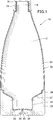
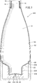
- FIG. 1 is a vertical cross-sectional view of a high viscosity liquid double container according to a first embodiment of the present invention. It is a vertical cross-sectional view of the molded article of the bottle main-body part of the double container for high viscosity liquids of 1st Embodiment of this invention, (a) is a whole vertical cross-sectional view, (b) is dotted line B of (a) FIG. 6 is an enlarged vertical cross-sectional view of a portion indicated by It is a perspective view of the one way valve of the 1st example used for the double container for high viscosity liquids of a 1st embodiment of the present invention.
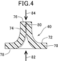
- FIG. 4 is a cross-sectional view taken along line IV-IV of FIG.
- the container cap 18 with the packing 16 is screwed to the discharge port 14 of the bottle main body 12 at the upper part. Be done.
- the bottom region of the bottle body 12 has an annular, horizontally extending recess 20, a conical surface 22 below it, a sealing cylindrical portion 24 below the conical surface 22, and a bottom 26 of the sealing cylindrical portion 24.
- an outer bottom cap 30 fitted in the recess 20 an inner bottom cap 32 fitted with the sealed cylindrical portion 24 of the bottle body 12 and the outer bottom cap 30, and further inside
- a one-way valve 40 fitted in a valve receiving hole 34 formed at the center of the bottom cap 32 is disposed.
- the fitting of the inner bottom cap 32 to the sealed cylindrical portion 24 and the fitting of the one-way valve 40 to the valve receiving hole 34 may use an adhesive to ensure fitting and sealing.
- the bottle body 12 is formed by sandwiching the parison with a split mold and pressing the parison into the mold with a blowing pressure. As shown in FIG. 2, the bottle main body 12 is a soft layer of three layers, from the inside, a low density polyethylene (LDPE) layer, an adhesive layer such as a polyolefin adhesive resin, and an ethylene vinyl alcohol copolymer (EVOH) layer. And a rigid outer layer 52 of polypropylene (PP).
- LDPE low density polyethylene
- EVOH ethylene vinyl alcohol copolymer
- PP polypropylene
- the flexible inner layer 50 and the rigid outer layer 52 of the bottle body 12 are not adhesive to each other and can be easily peeled off.
- the upper part of the bottle body 12, especially the discharge port 14, is integrated because the cross-sectional area of the discharge passage does not differ greatly from the thickness of the parison, and therefore the expansion due to the blow pressure is small and the thickness of the parison is maintained.
- the molded flexible inner layer 50 and the rigid outer layer 52 are firmly integrated and do not normally peel off at that portion.
- a parison lower than the bottom portion 26 is formed as a bottom burr 60 via the pinch portion PP.
- the conical surface 22, the sealed cylindrical portion 24, and the flexible inner layer 50 forming the inner surface of the bottom portion 26 are present in a single layer in the central portion.
- a rigid outer layer 52 extends on both sides of the bottom burr 60.
- the bottom burr 60 can be easily scraped from the bottle body 12 by the presence of the pinch portion PP having a small cross-sectional area.
- the end of one more flexible inner layer 50 and the end of the rigid outer layer 52 on both sides thereof are exposed.
- the flexible inner layer 50 and the rigid outer layer 52 peel off and a low pressure is generated between them, the flexible inner layer 50 and the rigid outer layer 52 in the portion of the bottom portion 26 scraped off the bottom burr 60 also peel away, and a thin gap is formed. . Accordingly, the air gap or space formed by the separation of the flexible inner layer 50 and the rigid outer layer 52 described above is always at the same atmospheric pressure as the outside air by the ventilation from this thin air gap.
- the outer bottom cap 30 is formed of an olefin resin such as polypropylene, high density polyethylene (HDPE), or a relatively high resin.
- olefin resin such as polypropylene, high density polyethylene (HDPE), or a relatively high resin.
- the inner bottom cap 32 is molded of an olefin resin such as polypropylene, high density polyethylene (HDPE) or a relatively high resin.
- an olefin resin such as polypropylene, high density polyethylene (HDPE) or a relatively high resin.
- the one-way valve 40 is formed of an elastic resin such as a thermoplastic elastomer. As shown in FIGS. 3 and 4, the one-way valve 40 includes a disk-shaped substrate portion 70 and a peak portion 74 gradually rising from one surface 72 of the substrate portion 70. The top portion 76 of the peak portion 74 is rectangular, and a vent groove 80 extending to the other surface 78 of the substrate portion 70 is formed in the central portion of the top portion 76.
- one-way valve 140 is molded of a resin having elasticity, such as a thermoplastic elastomer. As shown in FIGS. 5 and 6, the one-way valve 140 is disc-shaped and has a C-shaped ventilation groove 142 in the center. Although both sides of the vent groove 142 are separated, when there is no external load, the vent groove 142 is closed and the one-way valve 140 can not be vented.
- a resin having elasticity such as a thermoplastic elastomer
- the one-way valve 140 is indented into an annular inward inward groove 190 formed in the center of the inner bottom cap 132, as shown in FIG.
- the lower or outer air side support projection 192 of the inward groove 190 covers the vent groove 142, and the inner support projection 194 of the upper or inner bottom cap 132 of the inward groove 190 does not cover the vent groove 142.
- the one-way valve 140 deforms the portion VV surrounded by the C-shaped ventilation groove 142 so as to expand the ventilation groove 142, and the direction of the arrow 182 Vent to
- the vent groove 142 is not pushed, and the air flow in the direction of arrow 184 is It is impossible.
- a high viscosity liquid such as mayonnaise is accommodated in the high viscosity liquid double container 10 having the above-described configuration.
- the container cap 18 is removed, and the rigid outer layer 52 is crushed to push out the contents from the discharge port 14.
- the high viscosity liquid double container 10 is placed upright on a horizontal place such as a table.
- the rigid outer layer 52 tries to return to its original shape in response to reducing the crushing force of the high viscosity liquid double container 10.
- the flexible inner layer 50 can not inhale outside air to increase its volume.
- the flexible inner layer 50 and the rigid outer layer 52 peel off, creating a low pressure space between them. This low pressure pushes the vent groove 80 open to allow venting. Due to the ventilation of the ventilation groove 80, the space created by the separation of the flexible inner layer 50 and the rigid outer layer 52 becomes 1 atm, which is a stable state.
- the rigid outer layer 52 is crushed to further discharge the contents.
- the space between the flexible inner layer 50 and the rigid outer layer 52 becomes higher than 1 atm, the vent groove 80 is closed, and venting of the valve member 80 becomes impossible. Further crushing of the rigid outer layer 52 causes the space between the flexible inner layer 50 and the rigid outer layer 52 to be higher than 1 atmosphere, and the pressure higher than 1 atmosphere causes the flexible inner layer 50 to be crushed and the contents are discharged. .
- a center of the inner bottom cap 232 A one-way valve 40 fitted in a valve receiving hole 234 formed in the is disposed.
- the fitting of the inner bottom cap 232 to the sealing cylindrical portion 224 and the fitting of the one-way valve 40 to the valve receiving hole 234 may use an adhesive to ensure fitting and sealing.
- a plurality of longitudinally extending ventilating grooves 292 are formed in the upper end portion of the outer bottom cap 230, that is, the portion of the bottle main body 12 that is recessed into the recess 20. Ventilation flutes 292 vent the inside and outside of the outer bottom cap 230 at the recess 20.
- An inner bottom cap 232 fitted to the sealed cylindrical portion 224 of the bottle main body 12 and a valve receiving hole 324 formed at the center of the inner bottom cap 232 were fitted to the lower portion of the high viscosity liquid double container 210.
- a one way valve 40 is arranged.
- the fitting of the inner bottom cap 232 to the sealing cylindrical portion 224 and the fitting of the one-way valve 40 to the valve receiving hole 234 may use an adhesive to ensure fitting and sealing.
- the advantage of the high viscosity liquid double container 210 is that the high viscosity liquid double container 210 is also a high viscosity liquid double container if the water depth is smaller than the outer bottom cap 230 even where the water is collected. 210 does not absorb water and can be used normally.
Landscapes
- Engineering & Computer Science (AREA)
- Mechanical Engineering (AREA)
- Manufacturing & Machinery (AREA)
- Food Science & Technology (AREA)
- Health & Medical Sciences (AREA)
- Nutrition Science (AREA)
- Life Sciences & Earth Sciences (AREA)
- Chemical & Material Sciences (AREA)
- Polymers & Plastics (AREA)
- Ceramic Engineering (AREA)
- Containers And Packaging Bodies Having A Special Means To Remove Contents (AREA)
- Packages (AREA)
- Tubes (AREA)
- Thermally Insulated Containers For Foods (AREA)
- Packging For Living Organisms, Food Or Medicinal Products That Are Sensitive To Environmental Conditiond (AREA)
Abstract
Description
すなわち、一般の液体容器において、収容物の充填後、容器内の空間を真空にしたり窒素ガス等の不活性ガスを充填すること等によって、充填容器を開封するまで収容物の酸化を防ぐことは容易である。しかし、一般的には、容器を開封して収容物を一部消費し、容器内に使用残りの収容物が残留している状態では、容器内に収容物の消費量に対応した容積の外気が入り、残留収容物が酸化する。この酸化を防ぐため、収容物に酸化防止剤を含有することもある。
本発明は、比較的剛性な外容器と、該外容器内で収容物の充填量に対応して容量を変更可能な柔軟内容器とからなる二重容器によって高い粘性の液体を収容する場合の上述した問題に鑑みてなされたものである。本発明は、特に粘性の高い、例えば粘度1000~100,000mPa/sの液体を収容し、従来と大きく変わらない成形技術によって容易に製造可能で、比較的剛性な外容器と、該外容器内で収容物の充填量に対応して容積を変更可能な二重容器において、該内容物を、酸化させることなく収容し、外容器は当初の外形・寸法を維持し続け、残存収容物の量に拘わらず、外容器を押し潰すことによって収容物を吐出することができる高粘性液体用二重容器を提供することを目的とする。
また、容器の外面には、食用に供するための注意書、賞味期限、アレルギー関連注意書き、性能等が記載されている。前記容器の萎み変形によって、これらの記載が読み難くなったり、読むことが不可能にならない高粘性液体用二重容器を提供することを目的とする。
本発明は、粘度2000~90,000mPa/sの液体について、さらには粘度3000~80,000mPa/sの液体について好適に実施できる。
前記本発明において、前記一方向弁が、前記剛性外層容器部の底部に設けられていることを特徴とする。
(発明の第2実施態様)
前記本発明において、前記一方向弁が、前記剛性外層容器部の底部に取付けられた内側底キャップに固着されていることを特徴とする。
(発明の第3実施態様)
前記本発明において、前記一方向弁が、前記剛性外層容器部の底部に取付けられた外側底キャップに被われていることを特徴とする。
(構成)
本発明の第1実施形態の高粘性液体用二重容器10は、図1に示すように、上方部において、ボトル本体12の吐出口14にパッキン16付きの容器キャップ18が螺合され、蓋される。
ボトル本体12の底部領域は、環状で水平に延びた陥凹部20と、その下の円錐面22と、円錐面22の下方の密封円柱部24と、密封円柱部24の底部26とを有する。
他方、図4において、矢印84の方向から高い圧力が掛かるすなわち矢印82が記載された領域が矢印84が記載された領域より低圧になると、山部74は押し潰されて通気溝80をより強く閉じ、矢印84の方向の通気を不可能にする。
他方、図6において、矢印184の方向から高い圧力が掛かっても、部分VVは支持突出部192よって支持されているから、通気溝142は押しげられることはなく、矢印184の方向の通気は不可能である。
上述した構成の高粘性液体用二重容器10に、マヨネーズ等の高粘性液体を収容する。容器キャップ18を外して、剛性外層52を押し潰して吐出口14から収容物を押し出す。所定量の収容物の押し出し後、高粘性液体用二重容器10をテーブル等の水平なところに垂直に立てて置く。
(構成)
第2実施形態の高粘性液体用二重容器210の構成について以下に説明するが、第1実施形態の高粘性液体用二重容器10と同一の構成については、図面に第1実施形態と同一の参照番号を付して、その説明を省略する。
10、210 高粘性液体用二重容器
12 ボトル本体
14 吐出口
18 容器キャップ
20 陥凹部
22 円錐面
24、224 密封円柱部
26 底部
30、230 外側底キャップ
32、132、232 内側底キャップ
34、234 弁受け孔
40,140 一方向弁
50 柔軟性内層
52 剛性外層
60 底バリ
70 基板部
74 山部
76 頂上部
82,84 矢印
180 通気溝
190 陥入内溝
192 支持突出部
194 側支持突出部
292 通気縦溝
Claims (7)
- 互いに接触して成形されかつ部分的に剥離可能な剛性外層容器部と柔軟性内層容器部とを有し、前記剛性外層容器部と柔軟性内層容器部とが剥離してできた空間に外気を入れるための一方向弁を備えたことを特徴とする高粘性液体用二重容器。
- 前記一方向弁が、前記剛性外層容器部の底部に設けられていることを特徴とする請求項1に記載の高粘性液体用二重容器。
- 前記一方向弁が、前記剛性外層容器部の底部に取付けられた内側底キャップに固着されていることを特徴とする請求項1に記載の高粘性液体用二重容器。
- 前記一方向弁が、前記剛性外層容器部の底部に取付けられた外側底キャップに被われていることを特徴とする請求項1に記載の高粘性液体用二重容器。
- 収容物が、粘度1000~100,000mPa/sの液体であって、請求項1に記載の高粘性液体用二重容器に収容された二重容器入りの液体。
- 収容物が、マヨネーズであることを特徴とする請求項1に記載の二重容器入りの液体。
- 収容物が、グリースであることを特徴とする請求項1に記載の二重容器入りの液体。
Priority Applications (4)
| Application Number | Priority Date | Filing Date | Title |
|---|---|---|---|
| KR1020177013006A KR102439604B1 (ko) | 2014-11-18 | 2015-08-18 | 고점성 액체용 이중 용기 |
| EP15860602.0A EP3222547A4 (en) | 2014-11-18 | 2015-08-18 | Double-walled container for highly viscous liquid |
| US15/527,399 US20170320635A1 (en) | 2014-11-18 | 2015-08-18 | Double container for high-viscosity liquid |
| CN201580062012.XA CN107000897B9 (zh) | 2014-11-18 | 2015-08-18 | 高粘性液体用双层容器 |
Applications Claiming Priority (2)
| Application Number | Priority Date | Filing Date | Title |
|---|---|---|---|
| JP2014-233786 | 2014-11-18 | ||
| JP2014233786A JP2016097978A (ja) | 2014-11-18 | 2014-11-18 | 高粘性液体用二重容器 |
Publications (1)
| Publication Number | Publication Date |
|---|---|
| WO2016080030A1 true WO2016080030A1 (ja) | 2016-05-26 |
Family
ID=56013593
Family Applications (1)
| Application Number | Title | Priority Date | Filing Date |
|---|---|---|---|
| PCT/JP2015/073079 Ceased WO2016080030A1 (ja) | 2014-11-18 | 2015-08-18 | 高粘性液体用二重容器 |
Country Status (6)
| Country | Link |
|---|---|
| US (1) | US20170320635A1 (ja) |
| EP (1) | EP3222547A4 (ja) |
| JP (1) | JP2016097978A (ja) |
| KR (1) | KR102439604B1 (ja) |
| CN (1) | CN107000897B9 (ja) |
| WO (1) | WO2016080030A1 (ja) |
Families Citing this family (4)
| Publication number | Priority date | Publication date | Assignee | Title |
|---|---|---|---|---|
| JP6858450B2 (ja) * | 2017-05-31 | 2021-04-14 | 株式会社吉野工業所 | 合成樹脂製ブロー成形容器、及び内容物入り容器の製造方法 |
| WO2020029078A1 (zh) * | 2018-08-07 | 2020-02-13 | 台三荣实业有限公司 | 积层剥离容器及其制造方法 |
| TWI658970B (zh) | 2018-08-07 | 2019-05-11 | 臺三榮實業有限公司 | 積層剝離容器及其製法 |
| CN109018663A (zh) * | 2018-08-31 | 2018-12-18 | 沈杨 | 有装饰效果的吸盘牙膏 |
Citations (5)
| Publication number | Priority date | Publication date | Assignee | Title |
|---|---|---|---|---|
| JPS6265764A (ja) * | 1985-09-18 | 1987-03-25 | Maruyama Seisakusho:Kk | 高粘性体吐出器 |
| JPH03133748A (ja) * | 1989-10-13 | 1991-06-06 | Riyouichi Kitase | 注出容器 |
| JPH041153U (ja) * | 1990-04-12 | 1992-01-07 | ||
| JPH0724738U (ja) * | 1993-10-14 | 1995-05-12 | 武内プレス工業株式会社 | 多層押圧式容器 |
| JP2004231277A (ja) * | 2003-01-31 | 2004-08-19 | Yoshino Kogyosho Co Ltd | 壜容器 |
Family Cites Families (17)
| Publication number | Priority date | Publication date | Assignee | Title |
|---|---|---|---|---|
| JPS4936249B1 (ja) | 1969-09-16 | 1974-09-28 | ||
| US4154366A (en) * | 1977-01-31 | 1979-05-15 | Acres Alexander D | Dispensing container |
| DE8433745U1 (de) * | 1984-11-17 | 1985-03-28 | Kautex Werke Reinold Hagen AG, 5300 Bonn | Mit einer verschliessbaren oeffnung versehenen Verpackung |
| GB8506559D0 (en) * | 1985-03-13 | 1985-04-17 | Tpt Ltd | Liquid container & dispenser |
| US5301838A (en) * | 1991-01-23 | 1994-04-12 | Continental Pet Technologies, Inc. | Multilayer bottle with separable inner layer and method for forming same |
| FR2734247B1 (fr) * | 1995-05-17 | 1997-06-27 | Oreal | Dispositif de conditionnement et de distribution d'un produit liquide ou pateux |
| FR2753437B1 (fr) * | 1996-09-16 | 1998-10-30 | Oreal | Conditionnement pour produit de consistance liquide a pateuse |
| DE10017443A1 (de) * | 2000-04-07 | 2001-10-25 | Boehringer Ingelheim Pharma | Verfahren zum Herstellen eines mit einer Druckausgleichsöffnung versehenen Behälters und nach diesem Verfahren hergestellter Behälter |
| US6719173B2 (en) * | 2002-03-25 | 2004-04-13 | Owens-Brockway Plastic Products Inc. | Multilayer container package for dispensing a liquid product |
| JP3994142B2 (ja) * | 2002-09-30 | 2007-10-17 | 株式会社吉野工業所 | 注出容器 |
| CN1684881A (zh) * | 2002-10-18 | 2005-10-19 | 株式会社吉野工业所 | 注出容器 |
| JP4228362B2 (ja) * | 2003-01-31 | 2009-02-25 | 株式会社吉野工業所 | 合成樹脂製容器 |
| JP5267901B2 (ja) * | 2007-06-29 | 2013-08-21 | 株式会社吉野工業所 | ダイレクトブロー成形法による合成樹脂製二重容器 |
| JP4334597B2 (ja) * | 2008-03-04 | 2009-09-30 | 井上 淑枝 | 液体の収容容器、及びその排出方法 |
| CN201280264Y (zh) * | 2008-08-29 | 2009-07-29 | 广东富信电子科技有限公司 | 一种气液分隔气压式出液装置 |
| CN201580690U (zh) * | 2009-10-27 | 2010-09-15 | 袁祥生 | 一种液体储备及有压输出装置 |
| JP5295460B2 (ja) | 2013-03-26 | 2013-09-18 | キッコーマン株式会社 | 吐出容器 |
-
2014
- 2014-11-18 JP JP2014233786A patent/JP2016097978A/ja active Pending
-
2015
- 2015-08-18 CN CN201580062012.XA patent/CN107000897B9/zh not_active Expired - Fee Related
- 2015-08-18 KR KR1020177013006A patent/KR102439604B1/ko active Active
- 2015-08-18 US US15/527,399 patent/US20170320635A1/en not_active Abandoned
- 2015-08-18 EP EP15860602.0A patent/EP3222547A4/en not_active Withdrawn
- 2015-08-18 WO PCT/JP2015/073079 patent/WO2016080030A1/ja not_active Ceased
Patent Citations (5)
| Publication number | Priority date | Publication date | Assignee | Title |
|---|---|---|---|---|
| JPS6265764A (ja) * | 1985-09-18 | 1987-03-25 | Maruyama Seisakusho:Kk | 高粘性体吐出器 |
| JPH03133748A (ja) * | 1989-10-13 | 1991-06-06 | Riyouichi Kitase | 注出容器 |
| JPH041153U (ja) * | 1990-04-12 | 1992-01-07 | ||
| JPH0724738U (ja) * | 1993-10-14 | 1995-05-12 | 武内プレス工業株式会社 | 多層押圧式容器 |
| JP2004231277A (ja) * | 2003-01-31 | 2004-08-19 | Yoshino Kogyosho Co Ltd | 壜容器 |
Non-Patent Citations (1)
| Title |
|---|
| See also references of EP3222547A4 * |
Also Published As
| Publication number | Publication date |
|---|---|
| US20170320635A1 (en) | 2017-11-09 |
| KR20170084090A (ko) | 2017-07-19 |
| EP3222547A4 (en) | 2018-05-09 |
| JP2016097978A (ja) | 2016-05-30 |
| CN107000897B (zh) | 2019-09-17 |
| EP3222547A1 (en) | 2017-09-27 |
| CN107000897B9 (zh) | 2019-11-15 |
| CN107000897A (zh) | 2017-08-01 |
| KR102439604B1 (ko) | 2022-09-01 |
Similar Documents
| Publication | Publication Date | Title |
|---|---|---|
| JP6710462B2 (ja) | 吐出容器 | |
| CN103764516B (zh) | 吐出容器 | |
| CN108367831B (zh) | 双层容器和其制造方法 | |
| JP5295460B2 (ja) | 吐出容器 | |
| JP6059489B2 (ja) | 吐出容器 | |
| JP6547242B2 (ja) | 容器 | |
| WO2016080030A1 (ja) | 高粘性液体用二重容器 | |
| JP2018122860A (ja) | 積層剥離容器 | |
| JP6475542B2 (ja) | 吐出容器およびその吐出キャップとオーバーキャップ | |
| JP2017165452A (ja) | 二重容器 | |
| JP2011509893A (ja) | 注ぎ出しパッケージおよび注ぎ出し部材 | |
| JP2020023352A (ja) | 二重容器 | |
| JP6710468B2 (ja) | 吐出容器 | |
| JP6479502B2 (ja) | スクイズフォーマー容器 | |
| JP2018002232A (ja) | 二重容器 | |
| JP6372679B2 (ja) | レトルト食品用容器 | |
| JP7090463B2 (ja) | 吐出容器 | |
| JP2020001804A (ja) | 二重容器用キャップ、及び二重容器用キャップの製造方法 | |
| JP2020083462A (ja) | 注出容器 | |
| JP7142423B2 (ja) | 積層剥離容器 | |
| KR102127915B1 (ko) | 양방향 음용부를 가지는 식품용기 | |
| JP2020001774A (ja) | 二重容器用キャップ | |
| JP6559089B2 (ja) | 二重容器用キャップ | |
| JP6547267B2 (ja) | 口栓 | |
| JP2019206360A (ja) | 包装容器 |
Legal Events
| Date | Code | Title | Description |
|---|---|---|---|
| 121 | Ep: the epo has been informed by wipo that ep was designated in this application |
Ref document number: 15860602 Country of ref document: EP Kind code of ref document: A1 |
|
| ENP | Entry into the national phase |
Ref document number: 20177013006 Country of ref document: KR Kind code of ref document: A |
|
| WWE | Wipo information: entry into national phase |
Ref document number: 15527399 Country of ref document: US |
|
| NENP | Non-entry into the national phase |
Ref country code: DE |
|
| REEP | Request for entry into the european phase |
Ref document number: 2015860602 Country of ref document: EP |