WO2016084867A1 - 苗切断装置およびこの苗切断装置を有する接木装置 - Google Patents
苗切断装置およびこの苗切断装置を有する接木装置 Download PDFInfo
- Publication number
- WO2016084867A1 WO2016084867A1 PCT/JP2015/083129 JP2015083129W WO2016084867A1 WO 2016084867 A1 WO2016084867 A1 WO 2016084867A1 JP 2015083129 W JP2015083129 W JP 2015083129W WO 2016084867 A1 WO2016084867 A1 WO 2016084867A1
- Authority
- WO
- WIPO (PCT)
- Prior art keywords
- seedling
- blade
- stem
- shape
- hole
- Prior art date
- Legal status (The legal status is an assumption and is not a legal conclusion. Google has not performed a legal analysis and makes no representation as to the accuracy of the status listed.)
- Ceased
Links
Images


Classifications
-
- A—HUMAN NECESSITIES
- A01—AGRICULTURE; FORESTRY; ANIMAL HUSBANDRY; HUNTING; TRAPPING; FISHING
- A01G—HORTICULTURE; CULTIVATION OF VEGETABLES, FLOWERS, RICE, FRUIT, VINES, HOPS OR SEAWEED; FORESTRY; WATERING
- A01G2/00—Vegetative propagation
- A01G2/30—Grafting
- A01G2/35—Cutting; Inserting
-
- A—HUMAN NECESSITIES
- A01—AGRICULTURE; FORESTRY; ANIMAL HUSBANDRY; HUNTING; TRAPPING; FISHING
- A01G—HORTICULTURE; CULTIVATION OF VEGETABLES, FLOWERS, RICE, FRUIT, VINES, HOPS OR SEAWEED; FORESTRY; WATERING
- A01G2/00—Vegetative propagation
- A01G2/30—Grafting
- A01G2/32—Automatic apparatus therefor
-
- A—HUMAN NECESSITIES
- A01—AGRICULTURE; FORESTRY; ANIMAL HUSBANDRY; HUNTING; TRAPPING; FISHING
- A01G—HORTICULTURE; CULTIVATION OF VEGETABLES, FLOWERS, RICE, FRUIT, VINES, HOPS OR SEAWEED; FORESTRY; WATERING
- A01G3/00—Cutting implements specially adapted for horticultural purposes; Delimbing standing trees
Definitions
- the present invention relates to a seedling cutting device and a grafting device having the seedling cutting device.
- This seedling cutting device includes a cutting device that cuts a seedling for grafting, and a gripping tool that grips the seedling. A part of the seedling stalk is gripped by the gripping tool, and a portion not gripped by the seedling stalk gripping tool is cut by the cutting device.
- an object of the present invention is to provide a seedling cutting device capable of making the position of cutting the seedling for grafting and the shape of the cut surface of the stem constant.
- an object of the present invention is to provide a grafting device provided with the seedling cutting device.
- the seedling cutting device of the present invention is A pair of arms that can be opened and closed to sandwich a part of the stem of a grafting seedling;
- the stalk is provided so as to be able to advance and retreat, and a blade for cutting the stalk,
- At least one of the pair of arms has a through hole or a notch that penetrates a part of the arm along a direction in which the blade advances and retreats,
- the through-hole or notch is characterized in that at least a part thereof faces the part of the stem and at least a part of the blade passes therethrough.
- the blade passes through the through hole or notch to cut the stem.
- the blade is sandwiched between a pair of arms and cuts a part of the fixed stem, so that the stem is deformed according to the rigidity of the stem, and the cutting position of the stem and the shape of the cut surface of the stem vary. It can be prevented from occurring. Therefore, the cutting position and the cut surface shape can be made constant.
- the through hole or notch extends from a clamping surface for clamping the stem of the arm to a surface on the opposite side of the clamping surface of the arm.
- the through-hole or notch extends from the clamping surface to a surface on the opposite side to the clamping surface. For this reason, since the through hole is formed independently on one of the pair of arms, for example, even if the size of the stem is large and the position where the pair of arms sandwich the stem changes, the through hole is formed by the through hole. The position and shape of the passing path of the blade are not changed. Therefore, the cutting position and the cut surface shape can be made more certain. In other words, since the through hole or notch extends from the clamping surface to a surface opposite to the clamping surface, the through hole or cut formed in one of the pair of arms. Only the notch can define a passage through which the entire blade can pass. As a result, for example, the shape of the passage does not change even if the distance between the pair of arms increases because the pair of arms sandwich a part of the thick stem. Therefore, even if the thickness of the stem changes, the blade can surely reach the stem.
- the shape of the through hole is substantially the same as the shape of the blade.
- the shape of the through hole is substantially the same as the shape of the blade when viewed from the direction in which the blade advances and retreats, so that the through hole can guide the blade when the blade passes through the through hole. Therefore, the blade can be prevented from being greatly deformed.
- the blade When viewed from the direction in which the blade advances and retracts, the blade is formed in a y-shape.
- the blade when viewed from the direction in which the blade advances and retracts, the blade is formed in a y-shape. For this reason, for example, in order to improve the survival rate of grafting, if the cutting surface of the stem of the seedling for rootstock is made to be y-shaped, the blade need only cut the stem once, and the stem can be easily and reliably The cut surface can be formed in a y-shape.
- the grafting device of the present invention is The seedling cutting device is provided.
- the cutting position of the stem of the saplings and rootstock seedlings is cut by cutting the stems of the seedlings and rootstock seedlings with this seedling cutting device.
- it is possible to prevent variation in the cut surface shape of the stem and the cutting position and the cut surface shape can be made constant. Therefore, the cutting surface of the hogi seedling and the cutting surface of the rootstock seedling can be matched easily and reliably, and the survival rate of grafting between the hogi seedling and the rootstock seedling can be improved.
- the seedling cutting device and the grafting device of the present invention a part of the stem of the sandwiched seedling for cutting is cut, so that the cutting position of the stem and the cut surface shape of the stem can be made constant.
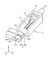
- FIG. 1 is a schematic perspective view of a grafting apparatus according to an embodiment of the present invention.
- the grafting device includes a cutting unit 1, a hotwood clip 2, a rootstock clip 3, and a seedling moving unit 4.
- the cutting part 1, the hotwood clip 2, and the rootstock clip 3 constitute a seedling cutting device.
- Hogi clip 2 is provided to be movable in the Y direction by an air cylinder (not shown).
- the hogi clip 2 has an arm portion 21 that holds a part of the stem of the hogi seedling 51.
- the arm portion 21 has two substantially rectangular parallelepiped arms 211 and 212 extending in parallel to each other in the Y direction.
- the arms 211 and 212 are arranged in order in the X direction, and are provided so as to be movable in the X direction by air cylinders (not shown). As the arms 211 and 212 move in the X direction, the arms 211 and 212 can be opened and closed. That is, the X direction is the opening / closing direction of the arms 211 and 212.
- the arms 211 and 212 sandwich a part of the stem of the hogi seedling 51 from the side, that is, from the X direction.
- a through-hole 210 is formed at one end of the arms 211 and 212 in the Y direction.
- the pair of arms 211 and 212 is an example of the pair of arms of the present invention.
- the through hole 210 is an example of the through hole of the present invention.
- the through-hole 210 of the arm 211 is a through-hole extending in the X direction from the holding surface that holds the stem of the hogi seedling 51 of the arm 211 to the surface opposite to the X direction with respect to the holding surface.
- the through hole 210 of the arm 212 is a through hole extending in the X direction from the holding surface that holds the stem of the safling seedling 51 of the arm 212 to the surface opposite to the X direction with respect to the holding surface.
- the through hole 210 is formed in a V shape when viewed from the X direction. That is, the shape of the through hole 210 viewed from the X direction is similar to the cut shape of the hogi seedling 51. A part of the through hole 210 faces a portion of the stem of the hogi seedling 51 that is sandwiched by the arm portion 21.
- the rootstock clip 3 is provided so as to be movable in the Y direction by an air cylinder (not shown).
- the rootstock clip 3 has an arm portion 31 that holds a part of the stem of the rootstock seedling 52.
- the arm portion 31 has two substantially rectangular parallelepiped arms 311 and 312 extending in parallel to each other in the Y direction.
- the arms 311 and 312 are arranged in order in the X direction, and are provided so as to be movable in the X direction by air cylinders (not shown). As the arms 311 and 312 move in the X direction, the arms 311 and 312 can be opened and closed. That is, the X direction is the opening / closing direction of the arms 311 and 312.
- the arms 311 and 312 sandwich a part of the stem of the rootstock seedling 52 from the side, that is, from the X direction.
- a through hole 310 is formed at one end of the arms 311 and 312 in the Y direction.
- the pair of arms 311 and 312 is an example of the pair of arms of the present invention.
- the through hole 310 is an example of the through hole of the present invention.
- the through-hole 310 of the arm 311 is a through-hole extending in the X direction from the holding surface that holds the stem of the rootstock seedling 52 of the arm 311 to the surface opposite to the X direction with respect to the holding surface.
- the through-hole 310 of the arm 312 is a through-hole extending in the X direction from the holding surface that holds the stem of the rootstock seedling 52 of the arm 312 to the surface opposite to the X direction with respect to the holding surface. .
- the through hole 310 is formed in a V shape when viewed from the X direction. That is, the shape of the through hole 310 viewed from the X direction is similar to the cut shape of the hogi seedling 51.
- a part of the through hole 310 faces a portion of the stem of the rootstock seedling 52 sandwiched between the pair of arms 31.
- the width of each part of the through hole 310 is such that the blade 111 can be inserted into the through hole 310. It is sufficiently larger than the thickness.
- the seedling moving part 4 has a scrub moving clip 6 for holding and moving the stem of the safling seedling 51 and a rootstock holding clip 7 for holding the stem of the rootstock seedling 52.
- the hogi moving clip 6 is located above the hogi clip 2 and is provided so as to be movable in the Z direction by an air cylinder (not shown).
- the hogi moving clip 6 has an arm portion 61 that holds a part of the stem of the hogi seedling 51.
- the arm portion 61 includes two substantially rectangular parallelepiped arms 611 and 612 extending in parallel to each other in the Y direction.
- the arms 611 and 612 are arranged in order in the X direction, and are provided so as to be movable in the X direction by air cylinders (not shown). As the arms 611 and 612 move in the X direction, the arms 611 and 612 can be opened and closed.
- the arms 611 and 612 sandwich a part of the stem of the hogi seedling 51 from the side, that is, from the X direction.
- the rootstock clamping clip 7 is located below the rootstock clip 3.
- the rootstock clamping clip 7 has an arm portion 71 that sandwiches a part of the stem of the rootstock seedling 52.
- the arm portion 71 has two substantially rectangular parallelepiped arms 711 and 712 extending in parallel to each other in the Y direction.
- the arms 711 and 712 are arranged in order in the X direction, and are provided so as to be movable in the X direction by air cylinders (not shown). As the arms 711 and 712 move in the X direction, the arms 711 and 712 can be opened and closed.
- the arms 711 and 712 sandwich a part of the stem of the rootstock seedling 52 from the side, that is, from the X direction.
- the cutting unit 1 includes a hogi cutting unit 11 that cuts the hogi seedling 51 and a root cutting unit 12 that cuts the rooting seedling 52.
- the hogi cutting part 11 extends in the X direction and is located on the ⁇ X direction side of the arm parts 21 and 61.
- the hogi cutting unit 11 has a blade 111 and an air cylinder 112.
- the blade 111 is provided so as to be movable in the X direction by an air cylinder 112. More specifically, the blade 111 can advance and retreat with respect to a portion of the stem of the hogi seedling 51 that is sandwiched by the arm portion 21.
- the blade 111 is formed in a V shape and is substantially the same as the shape of the through hole 210 of the arms 211 and 212.
- the blade 111 is an example of the blade of the present invention.
- the rootstock cutting unit 12 extends in the X direction and is positioned on the ⁇ X direction side of the pair of arms 31 and 71.
- the root cutting unit 12 has a blade 121 and an air cylinder 122.
- the blade 121 is provided so as to be movable in the X direction by an air cylinder 122. More specifically, the blade 121 can advance and retreat with respect to a portion of the stem of the rootstock seedling 52 sandwiched between the pair of arms 31.
- the blade 121 is formed in a y-shape and is substantially the same as the shape of the through hole 310 of the arms 311 and 312.
- the blade 121 is an example of the blade of the present invention.
- FIG. 2 shows the hogi cutting part 11 and the arm part 21 in an enlarged manner.
- FIG. 3 shows a state when the blade 111 moves in the X direction and cuts the stem of the hogi seedling 51. In FIGS. 2 and 3, the hogi seedling 51 is omitted.
- the root cutting part 12 and the arm part 31 are the same as the hogi cutting part 11 and the arm part 21.
- the hogi cutting part 11 has a main body part 110 and a blade mounting part 113.
- the main body 110 extends in the X direction, and is formed in a substantially U shape with the upper side (Z direction side) opened when viewed from the X direction.
- An air cylinder 112 is attached to one end surface in the X direction of the main body 110.
- a blade 111 and a blade attachment portion 113 to which the blade 111 is attached are accommodated in the main body 110.
- the blade mounting portion 113 is provided so as to be movable in the X direction in the main body 110 together with the blade 111 by an air cylinder 112.
- the blade 111 extends in the X direction and is orthogonal to the arm portion 21 extending in the Y direction.
- the blade 111 is located inside the through-hole 210 formed in the arms 211 and 212 when viewed from the X direction.
- the blade 111 is composed of two plate-shaped blades. Each blade has a tapered shape that gradually narrows toward the tip, that is, the stem of the hogi seedling 51.
- a substantially V-shaped cutout portion 261 extending in the Z direction is formed on a surface of the arm 211 facing the arm 212.
- the notch 261 is formed by a clamping surface 261A which is two planes and clamps a stalk of a hogi seedling.
- a substantially V-shaped notch 262 extending in the Z direction is formed on the surface of the arm 212 facing the arm 211. This notch 262 is formed by a clamping surface 262A which is two planes and clamps the stems of the seedlings.
- the blade 111 is moved in the X direction together with the blade mounting portion 113 by the air cylinder 112, and sequentially passes through the through-holes 210 of the arms 211 and 212 to cut the stalk of the seedling. ing.
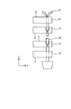
- FIG. 4 shows a state in which the hogi seedling 51 is sandwiched between the hogi clip 2 and the hogi moving clip 6 and the rootstock seedling 52 is sandwiched between the rootstock clip 3 and the rootstock clamping clip 7 from the X direction. It is the seen schematic diagram.
- the hogi seedling 51 is held by the arm portion 21 of the hogi clip 2 and the arm portion 61 of the hogi moving clip 6. Further, the rootstock seedling 52 is clamped by the arm portion 31 of the rootstock clip 3 and the arm portion 71 of the rootstock clamping clip 7.
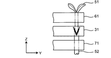
- FIG. 5 is a schematic diagram for explaining the operation when cutting the hogi seedling 51 and the rootstock seedling 52.
- the blade 111 is inserted into the through-hole 210 of the arm portion 21 while holding the spikelet seedling 51 between the arm portions 21 and 61, and the spikelet seedling 51 is cut into a V shape.
- the rootstock seedling 52 is cut into a Y shape by inserting the blade 121 through the through holes 310 of the pair of arms 31 while the rootstock seedling 52 is held between the arm portions 31 and 71.
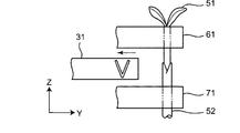
- FIG. 6 is a schematic diagram for explaining the operation of moving the arm portions 21 and 61 and aligning the cutting surface of the hogi seedling 51 and the cutting surface of the rootstock seedling 52.
- the arm portion 21 is opened, and the arm portion 21 is moved in the Y direction, that is, the direction in which it is retracted from the hogi seedling 51. Thereafter, the arm part 61 is moved in the Z direction, and the hogi seedling 51 sandwiched by the arm part 61 is lowered toward the rootstock seedling 52 sandwiched by the arm parts 31, 71 to cut the hogi seedling 51.
- the surface and the cut surface of the rootstock seedling 52 are matched.
- the cutting part of the rootstock seedling 52 remains sandwiched by the arm part 31.
- the position of the cutting surface of the rootstock seedling 52 can be fixed by the arm portion 31, and even when the rigidity of the stem of the rootstock seedling 52 is small, the stem is bent and the position of the cutting surface becomes unstable. Can be prevented. That is, the arm portion 31 serves as a guide. Therefore, the cutting surface of the hogi seedling 51 and the cutting surface of the rootstock seedling 52 can be easily and reliably matched.
- FIG. 7 is a schematic diagram for explaining a state in which the hogi seedling 51 and the rootstock seedling 52 are joined.
- FIG. 8 is a schematic diagram for explaining the operation of the rootstock clip.
- the arm portion 31 is opened, and the arm portion 31 is moved in the Y direction, that is, the direction in which it is retracted from the spikelet seedling 51 and rootstock seedling 52.
- FIG. 9 is a schematic diagram for explaining a state in which the clip 81 is attached to the joint portion between the hogi seedling 51 and the rootstock seedling 52.
- the clip 81 is attached to the joint portion between the hogi seedling 51 and the rootstock seedling 52, and the grafting of the hogi seedling 51 and the rootstock seedling 52 is completed.
- the through holes 210 and 310 are opposed to a part of the stems of the hogi seedling 51 or the rootstock seedling 52 sandwiched between the arm parts 11 and 31, and these penetrations
- the blades 111 and 121 pass through the holes 210 and 310 to cut the stem.
- the stem is deformed according to the rigidity of the stem, and the cutting position of the stem and the cut surface shape of the stem It is possible to prevent variation from occurring. Therefore, the cutting position and cut surface shape can be made constant.
- the through-hole 210 extends in the X direction from the clamping surfaces 261A and 262A that clamp the stems of the hogi seedling 51 of the arms 211 and 212 to the surface opposite to the X direction with respect to the clamping surfaces 261A and 262A. ing.
- the through-hole 310 extends in the X direction from the holding surface that holds the stem of the rootstock seedling 52 of the arms 311 and 312 to the surface opposite to the X direction of the holding surfaces of the arms 311 and 312. ing.
- the through-holes 210 and 310 are independently formed in each of the arms 211, 212, 311 and 312 so as to exhibit a V shape when viewed from the X direction.
- the shape of the through holes 210 and 310 does not change, and the blades 111 and 121 pass through.
- the position and shape of the path does not change. Therefore, the cutting position and the cut surface shape can be made more certain.
- the stems around the blades 111 and 121 are fixed by the arms 211 and 212, respectively. Therefore, the cutting position and the cut surface shape can be made more certain.
- the shape of the through holes 210 and 310 is substantially the same as the shape of the blades 111 and 121, so when the blades 111 and 121 pass through the through holes 210 and 310, The through holes 210 and 310 can guide the blades 111 and 121. Therefore, the blades 111 and 121 can be prevented from being greatly deformed.
- the blade 121 when viewed from the direction in which the blade 121 advances and retracts, the blade 121 is formed in a y-shape. For this reason, for example, in order to improve the survival rate of grafting, when the cutting surface of the stem of the rootstock seedling 52 is formed in a y shape, the blade 121 only needs to cut the stem once, and the stem can be cut easily and reliably.
- the surface can be formed in a y-shape.
- the said grafting apparatus is provided with the said seedling cutting device, by cutting the stems of the hogi seedling 51 and the rootstock seedling 52 with this seedling cutting device, the stems of the hogi seedling 51 and the rootstock seedling 52 are cut off. Variations in the cutting position and the cut surface shape of the stem can be prevented, and the cutting position and the cut surface shape can be made constant. Therefore, the cutting surface of the hogi seedling 51 and the cutting surface of the rootstock seedling 52 can be matched easily and reliably, and the survival rate of grafting of the hogi seedling 51 and the rootstock seedling 52 can be improved.
- the through-hole 210 is formed in each of the arms 211 and 212 of the arm portion 21. Moreover, although the through-hole 310 was formed in the arms 311 and 312 of the arm part 31, respectively, it is not restricted to this. The through hole only needs to be formed in at least one arm of the pair of arms.
- the through hole 210 of the arm 211 extends from the holding surface that holds the stem of the saplings 51 of the arm 211 to a surface opposite to the holding surface of the arm 211 in the X direction.
- the through hole extends in the direction, the present invention is not limited to this.
- the through hole may extend in any direction other than the X direction.
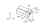
- the through-hole 215 may extend in the Y direction and be formed in a V shape across the two arms 2111, 2121. As shown in FIG.
- the through-hole 215 passes through the flat surfaces 261 ⁇ / b> A and 261 ⁇ / b> B constituting the notch 261 from the tip surface 2111 ⁇ / b> A of the arm 2111. Further, the through hole 215 passes through the flat surfaces 262A and 262B constituting the cutout portion 262 from the distal end surface 2112A of the arm 212. In this case, as shown in FIG. 12, even if the diameter of the stem of the seedling for grafting is large, the distance between the arms 2111, 2121 is increased, and the shape of the through hole 215 does not form a V-shape, the blade 111 Is moved downward, the blade 111 can be inserted into the through hole 215 and the stem can be cut.
- the pair of arms 2111, 2121 is an example of the pair of arms of the present invention.
- the through hole 215 is an example of the through hole of the present invention.
- FIG. 13 is a schematic plan view for explaining a modified example of the arm portion 21 of the hogi clip 2.
- FIG. 14 is a view taken in the direction of arrows AA in FIG.
- a notch 216 having a V-shaped cross section extending in the X direction is formed on the upper surface of the arms 2112 and 2122 of the arm portion 21.
- a blade 1111 capable of moving back and forth in the X direction is provided along the notch 216.
- 13 and 14 show a state in which the blade 1111 cuts the stem of the hogi seedling 51.
- the pair of arms 2112 and 2122 is an example of the pair of arms of the present invention.
- the notch 216 is an example of the notch of the present invention.
- the notch 216 penetrates the arm 212 in the X direction.
- the notch 216 is a bottomed notch having a predetermined depth in the X direction with respect to the arm 2122.
- the blade 1111 is formed in a V shape substantially the same as the notch 216 when viewed from the X direction, and is spaced upward from the notch 216 by a predetermined distance.
- the blade 111 is composed of two plate-shaped blades, and has a tapered shape that gradually decreases toward the tip. However, the blade 111 is not limited thereto, and has a flat tip portion like the blade 1111. It may be.
- FIG. 15 is a schematic plan view for explaining another modification of the arm portion 21 of the hogi clip 2.
- FIG. 16 is a view taken along the line BB in FIG.
- the arms 2113 and 2123 of the arm portion 21 are formed with U-shaped notches 217 that open in the Y direction when viewed from the X direction.
- the notch 217 penetrates the arms 2113 and 2123 in the X direction.
- the blade 1111 is positioned substantially at the center of the notch 217, and moves forward and backward in the notch 217 in the X direction.
- 15 and 16 show a state in which the blade 1111 cuts the stem of the hogi seedling 51.
- the pair of arms 2113 and 2123 is an example of the pair of arms of the present invention.
- the notch 217 is an example of the notch of the present invention.
- the through holes 210 and 310 are formed in a V shape when viewed from the X direction, but the present invention is not limited to this.
- the through-hole may have an arbitrary shape as long as the blade can pass, such as a square shape or a y-shape, when viewed from the X direction.
- a through hole whose shape when viewed from the X direction is a square shape, a circular shape, an elliptical shape, or the like may be used.
- a blade whose shape when viewed from the X direction is y-shaped or the like is used, or when viewed from the X direction instead of the blade 121, the shape is V-shaped. You may use the blade which becomes. It should be noted that the contact area between the stems of the hogi seedling 51 and the rootstock seedling 52 and the arms 211, 212, 311 and 312 is increased, and the stems of the hogi seedling 51 and the rootstock seedling 52 are armed.
- the shape when the through hole is viewed from the X direction is the same as or similar to the shape when the blade inserted into the through hole is viewed from the X direction from the viewpoint of being firmly held by 211, 212, 311 and 312 It is preferable to do so.
- the shape of the through hole when viewed from the X direction is the same as or similar to the shape of the blade inserted into the through hole when viewed from the X direction. Therefore, it is also preferable from the viewpoint of preventing the blade from greatly deviating from the target position.
- the shape of the through holes 210 and 310 is substantially the same as the shape of the blades 111 and 121 when viewed from the X direction, but is not limited thereto. While the through-hole is formed in a square shape, the shape of the blade may be different from the shape of the through-hole, such as a V shape or a y shape.
- the blade 111 is formed in a V shape when viewed from the X direction by two plate-shaped blades, and the blade 121 is formed from the X direction by two plate-shaped blades. When viewed, it was formed in a y-shape, but is not limited to this.
- the blade may be formed in an arbitrary shape such as a ⁇ shape (inverted V shape), an X shape, or an arc shape when viewed from the X direction.
- the blade may be formed in a V shape or the like from one blade.
- the blade 121 is formed in a y shape when viewed from the X direction, and the cutting surface of the stem is formed in a y shape only by the blade 121 cutting the stem once.
- the stem may be cut twice to form a cut surface of the stem in a y-shape.
- the hogi clip 2 and the rootstock clip 3 are provided, but the present invention is not limited to this.
- one pair of arms may sequentially sandwich the safflower seedling and the rootstock seedling, and cut the hogi seedling and the rootstock seedling.
- disconnection part 1 had the sap cutting part 11 which cut
- the hogi clip 2 and the rootstock clip 3 are provided to be movable in the Y direction by the air cylinder, and the hogi moving clip 6 of the seedling moving unit 4 is provided to be movable in the Z direction.
- the hogi clip and the rootstock clip may be fixed, and only the seedling moving part may be provided so as to be arbitrarily movable in the Y direction and the Z direction.
- the hogi clip 2 and the rootstock clip 3 are provided to be movable by the air cylinder, but the present invention is not limited to this.
- it may be provided to be movable by another drive mechanism such as an elastic body such as a spring, an electric cylinder, a hydraulic cylinder, or an electric motor.
- the arms 211, 212, 311 and 312 are provided to be movable in the X direction.
- the present invention is not limited to this.
- the arm may be provided so as to be rotatable and movable.
- the cutout portion 261 of the arm 211 is formed by the sandwiching surfaces 261A and 261B consisting of two planes
- the cutout portion 262 of the arm 212 is formed by the sandwiching surfaces 262A and 262B consisting of two planes.
- the sandwiching surface may be formed as a curved surface, may have an uneven surface, or may be subjected to surface processing such as knurl.
Landscapes
- Life Sciences & Earth Sciences (AREA)
- Environmental Sciences (AREA)
- Botany (AREA)
- Developmental Biology & Embryology (AREA)
- Biodiversity & Conservation Biology (AREA)
- Ecology (AREA)
- Forests & Forestry (AREA)
- Cultivation Of Plants (AREA)
- Supports For Plants (AREA)
- Transplanting Machines (AREA)
Abstract
Description
接木用の苗の茎の一部を挟持する開閉可能な一対のアームと、
上記茎の上記一部に対して進退可能に設けられると共に、上記茎を切断する刃と
を備え、
上記一対のアームの少なくとも一方は、上記刃が進退する方向に沿って上記アームの一部を貫通する貫通孔または切り欠きを有し、
上記貫通孔または切り欠きは、上記茎の上記一部に少なくとも一部が対向すると共に、上記刃の少なくとも一部が通ることを特徴としている。
上記貫通孔または切り欠きは、上記アームの上記茎を挟持する挟持面から、上記アームの上記挟持面に対して反対側の面まで延在している。
別の言い方をすると、上記貫通孔または切り欠きは、上記挟持面から、上記挟持面に対して反対側の面まで延在しているので、上記一対のアームの一方に形成した貫通孔または切り欠きだけで、刃の全部が通過可能な通路を画定できる。その結果、例えば、一対のアームが太い茎の一部を挟持することで、一対のアーム間の距離が広がっても、上記通路の形状は変化しない。したがって、上記茎の太さが変わっても、刃を茎に確実に到達させることができる。
上記刃が進退する方向から見たとき、上記貫通孔の形状は、上記刃の形状と略同一である。
上記刃が進退する方向から見たとき、上記刃は、y字状に形成されている。
上記苗切断装置を備えることを特徴としている。
51 穂木苗
52 台木苗
111,121,1111 刃
210,215,310 貫通孔
211,212,311,312,2111,2112,2113,2121,2122,2123 アーム
261A,261B,262A,262B 挟持面
Claims (5)
- 接木用の苗の茎の一部を挟持する開閉可能な一対のアームと、
上記茎の上記一部に対して進退可能に設けられると共に、上記茎を切断する刃と
を備え、
上記一対のアームの少なくとも一方は、上記刃が進退する方向に沿って上記アームの一部を貫通する貫通孔または切り欠きを有し、
上記貫通孔または切り欠きは、上記茎の上記一部に少なくとも一部が対向すると共に、上記刃の少なくとも一部が通ることを特徴とする苗切断装置。 - 請求項1に記載の苗切断装置において、
上記貫通孔または切り欠きは、上記アームの上記茎を挟持する挟持面から、上記アームの上記挟持面に対して反対側の面まで延在していることを特徴とする苗切断装置。 - 請求項1または2に記載の苗切断装置において、
上記刃が進退する方向から見たとき、上記貫通孔の形状は、上記刃の形状と略同一であることを特徴とする苗切断装置。 - 請求項1から3のいずれか一つに記載の苗切断装置において、
上記刃が進退する方向から見たとき、上記刃は、y字状に形成されていることを特徴とする苗切断装置。 - 請求項1から4のいずれか一つに記載の苗切断装置を備えることを特徴とする接木装置。
Priority Applications (5)
| Application Number | Priority Date | Filing Date | Title |
|---|---|---|---|
| JP2016561926A JP6356826B2 (ja) | 2014-11-26 | 2015-11-25 | 苗切断装置およびこの苗切断装置を有する接木装置 |
| CN201580064347.5A CN107249302B (zh) | 2014-11-26 | 2015-11-25 | 切苗装置以及具有该切苗装置的嫁接装置 |
| US15/529,206 US10595467B2 (en) | 2014-11-26 | 2015-11-25 | Seedling-cutting apparatus, and grafting apparatus having seedling-cutting apparatus |
| ES15862639T ES2880684T3 (es) | 2014-11-26 | 2015-11-25 | Aparato de corte de plántulas y aparato para injertar que tiene el aparato de corte de plántulas |
| EP15862639.0A EP3225097B1 (en) | 2014-11-26 | 2015-11-25 | Seedling-cutting apparatus, and grafting apparatus having seedling-cutting apparatus |
Applications Claiming Priority (2)
| Application Number | Priority Date | Filing Date | Title |
|---|---|---|---|
| JP2014238886 | 2014-11-26 | ||
| JP2014-238886 | 2014-11-26 |
Publications (1)
| Publication Number | Publication Date |
|---|---|
| WO2016084867A1 true WO2016084867A1 (ja) | 2016-06-02 |
Family
ID=56074419
Family Applications (1)
| Application Number | Title | Priority Date | Filing Date |
|---|---|---|---|
| PCT/JP2015/083129 Ceased WO2016084867A1 (ja) | 2014-11-26 | 2015-11-25 | 苗切断装置およびこの苗切断装置を有する接木装置 |
Country Status (6)
| Country | Link |
|---|---|
| US (1) | US10595467B2 (ja) |
| EP (1) | EP3225097B1 (ja) |
| JP (1) | JP6356826B2 (ja) |
| CN (1) | CN107249302B (ja) |
| ES (1) | ES2880684T3 (ja) |
| WO (1) | WO2016084867A1 (ja) |
Cited By (5)
| Publication number | Priority date | Publication date | Assignee | Title |
|---|---|---|---|---|
| CN107047073A (zh) * | 2017-03-23 | 2017-08-18 | 华南农业大学 | 一种多株同步蔬菜种苗嫁接装置 |
| CN109089587A (zh) * | 2018-09-12 | 2018-12-28 | 聊城大学 | 一种实现废料收集的嫁接夹持与切割机构 |
| WO2020117057A1 (en) * | 2018-12-06 | 2020-06-11 | Visser 's-Gravendeel Holding B.V. | Graft system |
| CN111418428A (zh) * | 2020-04-21 | 2020-07-17 | 黄勤 | 一种提高苗木嫁接培育的方法 |
| CN114532089A (zh) * | 2022-03-22 | 2022-05-27 | 海南大学 | 一种天然橡胶枝条芽点提取机 |
Families Citing this family (24)
| Publication number | Priority date | Publication date | Assignee | Title |
|---|---|---|---|---|
| US11800834B2 (en) * | 2017-09-25 | 2023-10-31 | Roy Ekland | Method and apparatus for a phytoimmune system to manage diseases in fruit trees |
| CN108293467B (zh) * | 2018-03-31 | 2020-08-18 | 浙江金大田农林科技有限公司 | 一种用于果树嫁接的机器人 |
| JP6806404B2 (ja) * | 2018-06-06 | 2021-01-06 | グランドグリーン株式会社 | 接ぎ木用部材、接ぎ木用部材セット、接ぎ木用固定具及び接ぎ木苗の生産方法 |
| CN108811841B (zh) * | 2018-06-27 | 2020-12-04 | 临沂文衡信息技术有限公司 | 一种苗木嫁接用修剪装置 |
| CN108886996B (zh) * | 2018-09-12 | 2024-05-24 | 常宁市山茶油生态农业开发有限公司 | 一种自动上料的嫁接夹持与切割装置及其嫁接方法 |
| KR102138443B1 (ko) * | 2018-12-07 | 2020-07-27 | 이종웅 | 접목용 접수밑단 절단장치 |
| CN109906791B (zh) * | 2019-04-08 | 2021-02-05 | 温州职业技术学院 | 一种砧木切口机构及其工作方法 |
| CN110447405B (zh) * | 2019-09-19 | 2021-04-27 | 浙江山茶之都农业开发股份有限公司 | 一种茶花培育方法 |
| CN110800492B (zh) * | 2019-09-30 | 2025-03-25 | 北京农业智能装备技术研究中心 | 一种拢苗定位切削机构 |
| WO2021131356A1 (ja) * | 2019-12-27 | 2021-07-01 | 株式会社エルム | 接ぎ木装置 |
| CN112425391A (zh) * | 2020-11-27 | 2021-03-02 | 周明鸿 | 一种商品植物自动嫁接设备 |
| CN113508697B (zh) * | 2021-04-23 | 2023-01-13 | 山西省农业科学院果树研究所 | 一种适用于扁桃树嫁接的接穗削切辅助装置 |
| CN113519286A (zh) * | 2021-08-11 | 2021-10-22 | 江西省农业科学院农业工程研究所 | 一种蔬菜嫁接方法及其机构 |
| CN113767767B (zh) * | 2021-10-22 | 2023-01-31 | 山东泽农润青农业科技有限公司 | 一种批量嫁接设备及批量嫁接方法 |
| CN114097446B (zh) * | 2021-11-24 | 2023-03-14 | 湖南科技学院 | 一种油茶种植专用育苗装置 |
| EP4482295A1 (en) * | 2022-02-21 | 2025-01-01 | Hendrik Baars | Method of stem grafting and an apparatus for performing the method |
| CN114847019B (zh) * | 2022-04-20 | 2023-04-28 | 重庆武陵山油茶研究院有限公司 | 一种无损伤精准柔性对接油茶幼苗嫁接设备 |
| CN114847020B (zh) * | 2022-06-23 | 2023-08-04 | 高秀云 | 一种用于园林绿化的嫁接苗木培育装置 |
| CN117136736B (zh) * | 2023-10-07 | 2025-06-24 | 宁波市农业科学研究院 | 一种西瓜快速嫁接设备及方法 |
| NL2036571B1 (en) * | 2023-12-18 | 2025-07-08 | Ig Specials B V | Systems, tools and methods for preparing and grafting plant stems |
| WO2025132675A1 (en) | 2023-12-18 | 2025-06-26 | Ig Specials B.V. | Systems, tools and methods for preparing and grafting plant stems |
| NL2036570B1 (en) * | 2023-12-18 | 2025-07-08 | Ig Specials B V | Systems, tools and methods for preparing and grafting plant stems |
| CN120113491B (zh) * | 2025-05-13 | 2025-07-08 | 中国农业科学院农业信息研究所 | 一种末端执行器 |
| CN120113490B (zh) * | 2025-05-13 | 2025-08-08 | 中国农业科学院农业信息研究所 | 一种嫁接设备 |
Citations (4)
| Publication number | Priority date | Publication date | Assignee | Title |
|---|---|---|---|---|
| JPS4880322A (ja) * | 1972-02-03 | 1973-10-27 | ||
| JP2009112261A (ja) * | 2007-11-07 | 2009-05-28 | Mekatekku Kk | 接ぎ木苗の製造方法及び製造装置 |
| JP2014073090A (ja) * | 2012-10-03 | 2014-04-24 | Mikuni Agri Techno:Kk | 接木用台木処理装置およびそれを用いる接木装置 |
| JP2014073093A (ja) * | 2012-10-03 | 2014-04-24 | Mikuni Agri Techno:Kk | 接木用クリップ装着装置およびそれを用いる接木装置 |
Family Cites Families (12)
| Publication number | Priority date | Publication date | Assignee | Title |
|---|---|---|---|---|
| US5414958A (en) * | 1992-09-24 | 1995-05-16 | Iwatani Sangyo Kabushiki Kaisha | Method and apparatus for uniting a scion to a stock |
| US5499578A (en) * | 1995-02-23 | 1996-03-19 | Payne; Patricia K. | Sausage cutter |
| JP3557754B2 (ja) | 1995-10-23 | 2004-08-25 | 井関農機株式会社 | 接ぎ木装置 |
| JP2004194544A (ja) * | 2002-12-17 | 2004-07-15 | Yanmar Agricult Equip Co Ltd | 接ぎ木用苗の切断方法及びその装置 |
| CN2612227Y (zh) * | 2003-01-22 | 2004-04-21 | 魏均倚 | 植物嫁接切口装置 |
| JP2004350550A (ja) * | 2003-05-28 | 2004-12-16 | Yanmar Co Ltd | 接木装置 |
| JP2005224152A (ja) * | 2004-02-12 | 2005-08-25 | Yanmar Co Ltd | 接ぎ木苗の製造装置 |
| US6918205B1 (en) * | 2004-05-06 | 2005-07-19 | Thomas Sowinski | Grafting tool |
| CN1806498A (zh) * | 2006-01-26 | 2006-07-26 | 东北农业大学 | 插接式自动嫁接机 |
| JP5087998B2 (ja) * | 2007-06-01 | 2012-12-05 | シブヤ精機株式会社 | 接木装置 |
| JP2010166877A (ja) * | 2009-01-26 | 2010-08-05 | Mekatekku Kk | 接ぎ木苗の切断装置及び切断方法 |
| CN201403353Y (zh) * | 2009-05-22 | 2010-02-17 | 王桂君 | 蔬菜嫁接器 |
-
2015
- 2015-11-25 ES ES15862639T patent/ES2880684T3/es active Active
- 2015-11-25 EP EP15862639.0A patent/EP3225097B1/en active Active
- 2015-11-25 US US15/529,206 patent/US10595467B2/en active Active
- 2015-11-25 CN CN201580064347.5A patent/CN107249302B/zh active Active
- 2015-11-25 JP JP2016561926A patent/JP6356826B2/ja active Active
- 2015-11-25 WO PCT/JP2015/083129 patent/WO2016084867A1/ja not_active Ceased
Patent Citations (4)
| Publication number | Priority date | Publication date | Assignee | Title |
|---|---|---|---|---|
| JPS4880322A (ja) * | 1972-02-03 | 1973-10-27 | ||
| JP2009112261A (ja) * | 2007-11-07 | 2009-05-28 | Mekatekku Kk | 接ぎ木苗の製造方法及び製造装置 |
| JP2014073090A (ja) * | 2012-10-03 | 2014-04-24 | Mikuni Agri Techno:Kk | 接木用台木処理装置およびそれを用いる接木装置 |
| JP2014073093A (ja) * | 2012-10-03 | 2014-04-24 | Mikuni Agri Techno:Kk | 接木用クリップ装着装置およびそれを用いる接木装置 |
Non-Patent Citations (1)
| Title |
|---|
| See also references of EP3225097A4 * |
Cited By (8)
| Publication number | Priority date | Publication date | Assignee | Title |
|---|---|---|---|---|
| CN107047073A (zh) * | 2017-03-23 | 2017-08-18 | 华南农业大学 | 一种多株同步蔬菜种苗嫁接装置 |
| CN107047073B (zh) * | 2017-03-23 | 2020-03-17 | 华南农业大学 | 一种多株同步蔬菜种苗嫁接装置 |
| CN109089587A (zh) * | 2018-09-12 | 2018-12-28 | 聊城大学 | 一种实现废料收集的嫁接夹持与切割机构 |
| CN109089587B (zh) * | 2018-09-12 | 2024-01-30 | 聊城大学 | 一种实现废料收集的嫁接夹持与切割机构 |
| WO2020117057A1 (en) * | 2018-12-06 | 2020-06-11 | Visser 's-Gravendeel Holding B.V. | Graft system |
| NL2022145B1 (en) * | 2018-12-06 | 2020-06-30 | Visser S Gravendeel Holding B V | Graft system |
| CN111418428A (zh) * | 2020-04-21 | 2020-07-17 | 黄勤 | 一种提高苗木嫁接培育的方法 |
| CN114532089A (zh) * | 2022-03-22 | 2022-05-27 | 海南大学 | 一种天然橡胶枝条芽点提取机 |
Also Published As
| Publication number | Publication date |
|---|---|
| ES2880684T3 (es) | 2021-11-25 |
| CN107249302A (zh) | 2017-10-13 |
| JPWO2016084867A1 (ja) | 2017-10-26 |
| JP6356826B2 (ja) | 2018-07-11 |
| US20170325409A1 (en) | 2017-11-16 |
| EP3225097B1 (en) | 2021-06-23 |
| CN107249302B (zh) | 2020-10-30 |
| US10595467B2 (en) | 2020-03-24 |
| EP3225097A4 (en) | 2018-07-18 |
| EP3225097A1 (en) | 2017-10-04 |
Similar Documents
| Publication | Publication Date | Title |
|---|---|---|
| JP6356826B2 (ja) | 苗切断装置およびこの苗切断装置を有する接木装置 | |
| US20100318103A1 (en) | Integrated double clips applier with division device for clamping clips | |
| RU2013120005A (ru) | Хирургический инструмент с элементом бранши | |
| JP2015515334A5 (ja) | ||
| US10077975B2 (en) | Broadhead having an adjustable cutting diameter | |
| CN1281634A (zh) | 嫁接用砧木切断装置 | |
| JP5436644B1 (ja) | 電線切断工具 | |
| CN106923876B (zh) | 组织闭合装置及包括该组织闭合装置的医疗器械 | |
| JP3168225U (ja) | プライヤー | |
| JP5442653B2 (ja) | 開閉規制具、及び該開閉規制具を備えるワニ口クリップ | |
| EP2544604A1 (en) | Ring handled device and method of manufacturing same | |
| US20160051024A1 (en) | Hair clip assembly | |
| JPWO2023200706A5 (ja) | ||
| JP3189051U (ja) | 雑草除去具 | |
| JP3184448U (ja) | 毛抜き | |
| JP2009034805A (ja) | スプリットリング用のプライヤー | |
| CN203973574U (zh) | 附钳夹的剪刀 | |
| JP5886169B2 (ja) | プライヤ | |
| JP5631132B2 (ja) | 操作チェーンの接続用工具 | |
| JP6910089B1 (ja) | 面積可変ストッパ | |
| US20130333225A1 (en) | Diagonal cutter and wire stripper tool | |
| FR2562788A1 (fr) | Pince diathermique pour micro-chirurgie | |
| JP2020080615A (ja) | 間接活線工事用クリップ | |
| JP3189694U (ja) | 鋏 | |
| WO2017212097A3 (es) | Conector por desplazamiento del aislante |
Legal Events
| Date | Code | Title | Description |
|---|---|---|---|
| 121 | Ep: the epo has been informed by wipo that ep was designated in this application |
Ref document number: 15862639 Country of ref document: EP Kind code of ref document: A1 |
|
| ENP | Entry into the national phase |
Ref document number: 2016561926 Country of ref document: JP Kind code of ref document: A |
|
| WWE | Wipo information: entry into national phase |
Ref document number: 15529206 Country of ref document: US |
|
| NENP | Non-entry into the national phase |
Ref country code: DE |
|
| REEP | Request for entry into the european phase |
Ref document number: 2015862639 Country of ref document: EP |