WO2016084969A1 - 衝突回避装置 - Google Patents
衝突回避装置 Download PDFInfo
- Publication number
- WO2016084969A1 WO2016084969A1 PCT/JP2015/083508 JP2015083508W WO2016084969A1 WO 2016084969 A1 WO2016084969 A1 WO 2016084969A1 JP 2015083508 W JP2015083508 W JP 2015083508W WO 2016084969 A1 WO2016084969 A1 WO 2016084969A1
- Authority
- WO
- WIPO (PCT)
- Prior art keywords
- collision avoidance
- collision
- avoidance
- vehicle
- control unit
- Prior art date
- Legal status (The legal status is an assumption and is not a legal conclusion. Google has not performed a legal analysis and makes no representation as to the accuracy of the status listed.)
- Ceased
Links
Images




Classifications
-
- G—PHYSICS
- G08—SIGNALLING
- G08G—TRAFFIC CONTROL SYSTEMS
- G08G1/00—Traffic control systems for road vehicles
- G08G1/16—Anti-collision systems
-
- B—PERFORMING OPERATIONS; TRANSPORTING
- B60—VEHICLES IN GENERAL
- B60T—VEHICLE BRAKE CONTROL SYSTEMS OR PARTS THEREOF; BRAKE CONTROL SYSTEMS OR PARTS THEREOF, IN GENERAL; ARRANGEMENT OF BRAKING ELEMENTS ON VEHICLES IN GENERAL; PORTABLE DEVICES FOR PREVENTING UNWANTED MOVEMENT OF VEHICLES; VEHICLE MODIFICATIONS TO FACILITATE COOLING OF BRAKES
- B60T7/00—Brake-action initiating means
- B60T7/12—Brake-action initiating means for automatic initiation; for initiation not subject to will of driver or passenger
-
- B—PERFORMING OPERATIONS; TRANSPORTING
- B60—VEHICLES IN GENERAL
- B60T—VEHICLE BRAKE CONTROL SYSTEMS OR PARTS THEREOF; BRAKE CONTROL SYSTEMS OR PARTS THEREOF, IN GENERAL; ARRANGEMENT OF BRAKING ELEMENTS ON VEHICLES IN GENERAL; PORTABLE DEVICES FOR PREVENTING UNWANTED MOVEMENT OF VEHICLES; VEHICLE MODIFICATIONS TO FACILITATE COOLING OF BRAKES
- B60T7/00—Brake-action initiating means
- B60T7/12—Brake-action initiating means for automatic initiation; for initiation not subject to will of driver or passenger
- B60T7/22—Brake-action initiating means for automatic initiation; for initiation not subject to will of driver or passenger initiated by contact of vehicle, e.g. bumper, with an external object, e.g. another vehicle, or by means of contactless obstacle detectors mounted on the vehicle
-
- B—PERFORMING OPERATIONS; TRANSPORTING
- B60—VEHICLES IN GENERAL
- B60T—VEHICLE BRAKE CONTROL SYSTEMS OR PARTS THEREOF; BRAKE CONTROL SYSTEMS OR PARTS THEREOF, IN GENERAL; ARRANGEMENT OF BRAKING ELEMENTS ON VEHICLES IN GENERAL; PORTABLE DEVICES FOR PREVENTING UNWANTED MOVEMENT OF VEHICLES; VEHICLE MODIFICATIONS TO FACILITATE COOLING OF BRAKES
- B60T8/00—Arrangements for adjusting wheel-braking force to meet varying vehicular or ground-surface conditions, e.g. limiting or varying distribution of braking force
-
- B—PERFORMING OPERATIONS; TRANSPORTING
- B60—VEHICLES IN GENERAL
- B60T—VEHICLE BRAKE CONTROL SYSTEMS OR PARTS THEREOF; BRAKE CONTROL SYSTEMS OR PARTS THEREOF, IN GENERAL; ARRANGEMENT OF BRAKING ELEMENTS ON VEHICLES IN GENERAL; PORTABLE DEVICES FOR PREVENTING UNWANTED MOVEMENT OF VEHICLES; VEHICLE MODIFICATIONS TO FACILITATE COOLING OF BRAKES
- B60T8/00—Arrangements for adjusting wheel-braking force to meet varying vehicular or ground-surface conditions, e.g. limiting or varying distribution of braking force
- B60T8/17—Using electrical or electronic regulation means to control braking
- B60T8/172—Determining control parameters used in the regulation, e.g. by calculations involving measured or detected parameters
-
- B—PERFORMING OPERATIONS; TRANSPORTING
- B60—VEHICLES IN GENERAL
- B60T—VEHICLE BRAKE CONTROL SYSTEMS OR PARTS THEREOF; BRAKE CONTROL SYSTEMS OR PARTS THEREOF, IN GENERAL; ARRANGEMENT OF BRAKING ELEMENTS ON VEHICLES IN GENERAL; PORTABLE DEVICES FOR PREVENTING UNWANTED MOVEMENT OF VEHICLES; VEHICLE MODIFICATIONS TO FACILITATE COOLING OF BRAKES
- B60T8/00—Arrangements for adjusting wheel-braking force to meet varying vehicular or ground-surface conditions, e.g. limiting or varying distribution of braking force
- B60T8/17—Using electrical or electronic regulation means to control braking
- B60T8/1755—Brake regulation specially adapted to control the stability of the vehicle, e.g. taking into account yaw rate or transverse acceleration in a curve
- B60T8/17551—Brake regulation specially adapted to control the stability of the vehicle, e.g. taking into account yaw rate or transverse acceleration in a curve determining control parameters related to vehicle stability used in the regulation, e.g. by calculations involving measured or detected parameters
-
- B—PERFORMING OPERATIONS; TRANSPORTING
- B60—VEHICLES IN GENERAL
- B60T—VEHICLE BRAKE CONTROL SYSTEMS OR PARTS THEREOF; BRAKE CONTROL SYSTEMS OR PARTS THEREOF, IN GENERAL; ARRANGEMENT OF BRAKING ELEMENTS ON VEHICLES IN GENERAL; PORTABLE DEVICES FOR PREVENTING UNWANTED MOVEMENT OF VEHICLES; VEHICLE MODIFICATIONS TO FACILITATE COOLING OF BRAKES
- B60T8/00—Arrangements for adjusting wheel-braking force to meet varying vehicular or ground-surface conditions, e.g. limiting or varying distribution of braking force
- B60T8/17—Using electrical or electronic regulation means to control braking
- B60T8/1755—Brake regulation specially adapted to control the stability of the vehicle, e.g. taking into account yaw rate or transverse acceleration in a curve
- B60T8/17558—Brake regulation specially adapted to control the stability of the vehicle, e.g. taking into account yaw rate or transverse acceleration in a curve specially adapted for collision avoidance or collision mitigation
-
- B—PERFORMING OPERATIONS; TRANSPORTING
- B60—VEHICLES IN GENERAL
- B60W—CONJOINT CONTROL OF VEHICLE SUB-UNITS OF DIFFERENT TYPE OR DIFFERENT FUNCTION; CONTROL SYSTEMS SPECIALLY ADAPTED FOR HYBRID VEHICLES; ROAD VEHICLE DRIVE CONTROL SYSTEMS FOR PURPOSES NOT RELATED TO THE CONTROL OF A PARTICULAR SUB-UNIT
- B60W10/00—Conjoint control of vehicle sub-units of different type or different function
- B60W10/04—Conjoint control of vehicle sub-units of different type or different function including control of propulsion units
- B60W10/06—Conjoint control of vehicle sub-units of different type or different function including control of propulsion units including control of combustion engines
-
- B—PERFORMING OPERATIONS; TRANSPORTING
- B60—VEHICLES IN GENERAL
- B60W—CONJOINT CONTROL OF VEHICLE SUB-UNITS OF DIFFERENT TYPE OR DIFFERENT FUNCTION; CONTROL SYSTEMS SPECIALLY ADAPTED FOR HYBRID VEHICLES; ROAD VEHICLE DRIVE CONTROL SYSTEMS FOR PURPOSES NOT RELATED TO THE CONTROL OF A PARTICULAR SUB-UNIT
- B60W10/00—Conjoint control of vehicle sub-units of different type or different function
- B60W10/18—Conjoint control of vehicle sub-units of different type or different function including control of braking systems
- B60W10/184—Conjoint control of vehicle sub-units of different type or different function including control of braking systems with wheel brakes
-
- B—PERFORMING OPERATIONS; TRANSPORTING
- B60—VEHICLES IN GENERAL
- B60W—CONJOINT CONTROL OF VEHICLE SUB-UNITS OF DIFFERENT TYPE OR DIFFERENT FUNCTION; CONTROL SYSTEMS SPECIALLY ADAPTED FOR HYBRID VEHICLES; ROAD VEHICLE DRIVE CONTROL SYSTEMS FOR PURPOSES NOT RELATED TO THE CONTROL OF A PARTICULAR SUB-UNIT
- B60W30/00—Purposes of road vehicle drive control systems not related to the control of a particular sub-unit, e.g. of systems using conjoint control of vehicle sub-units
- B60W30/08—Active safety systems predicting or avoiding probable or impending collision or attempting to minimise its consequences
-
- B—PERFORMING OPERATIONS; TRANSPORTING
- B60—VEHICLES IN GENERAL
- B60W—CONJOINT CONTROL OF VEHICLE SUB-UNITS OF DIFFERENT TYPE OR DIFFERENT FUNCTION; CONTROL SYSTEMS SPECIALLY ADAPTED FOR HYBRID VEHICLES; ROAD VEHICLE DRIVE CONTROL SYSTEMS FOR PURPOSES NOT RELATED TO THE CONTROL OF A PARTICULAR SUB-UNIT
- B60W30/00—Purposes of road vehicle drive control systems not related to the control of a particular sub-unit, e.g. of systems using conjoint control of vehicle sub-units
- B60W30/08—Active safety systems predicting or avoiding probable or impending collision or attempting to minimise its consequences
- B60W30/09—Taking automatic action to avoid collision, e.g. braking and steering
-
- B—PERFORMING OPERATIONS; TRANSPORTING
- B60—VEHICLES IN GENERAL
- B60W—CONJOINT CONTROL OF VEHICLE SUB-UNITS OF DIFFERENT TYPE OR DIFFERENT FUNCTION; CONTROL SYSTEMS SPECIALLY ADAPTED FOR HYBRID VEHICLES; ROAD VEHICLE DRIVE CONTROL SYSTEMS FOR PURPOSES NOT RELATED TO THE CONTROL OF A PARTICULAR SUB-UNIT
- B60W50/00—Details of control systems for road vehicle drive control not related to the control of a particular sub-unit, e.g. process diagnostic or vehicle driver interfaces
- B60W50/08—Interaction between the driver and the control system
- B60W50/10—Interpretation of driver requests or demands
-
- B—PERFORMING OPERATIONS; TRANSPORTING
- B60—VEHICLES IN GENERAL
- B60W—CONJOINT CONTROL OF VEHICLE SUB-UNITS OF DIFFERENT TYPE OR DIFFERENT FUNCTION; CONTROL SYSTEMS SPECIALLY ADAPTED FOR HYBRID VEHICLES; ROAD VEHICLE DRIVE CONTROL SYSTEMS FOR PURPOSES NOT RELATED TO THE CONTROL OF A PARTICULAR SUB-UNIT
- B60W50/00—Details of control systems for road vehicle drive control not related to the control of a particular sub-unit, e.g. process diagnostic or vehicle driver interfaces
- B60W50/08—Interaction between the driver and the control system
- B60W50/14—Means for informing the driver, warning the driver or prompting a driver intervention
-
- G—PHYSICS
- G08—SIGNALLING
- G08G—TRAFFIC CONTROL SYSTEMS
- G08G1/00—Traffic control systems for road vehicles
- G08G1/16—Anti-collision systems
- G08G1/166—Anti-collision systems for active traffic, e.g. moving vehicles, pedestrians, bikes
-
- B—PERFORMING OPERATIONS; TRANSPORTING
- B60—VEHICLES IN GENERAL
- B60T—VEHICLE BRAKE CONTROL SYSTEMS OR PARTS THEREOF; BRAKE CONTROL SYSTEMS OR PARTS THEREOF, IN GENERAL; ARRANGEMENT OF BRAKING ELEMENTS ON VEHICLES IN GENERAL; PORTABLE DEVICES FOR PREVENTING UNWANTED MOVEMENT OF VEHICLES; VEHICLE MODIFICATIONS TO FACILITATE COOLING OF BRAKES
- B60T2201/00—Particular use of vehicle brake systems; Special systems using also the brakes; Special software modules within the brake system controller
- B60T2201/02—Active or adaptive cruise control system; Distance control
- B60T2201/022—Collision avoidance systems
-
- B—PERFORMING OPERATIONS; TRANSPORTING
- B60—VEHICLES IN GENERAL
- B60T—VEHICLE BRAKE CONTROL SYSTEMS OR PARTS THEREOF; BRAKE CONTROL SYSTEMS OR PARTS THEREOF, IN GENERAL; ARRANGEMENT OF BRAKING ELEMENTS ON VEHICLES IN GENERAL; PORTABLE DEVICES FOR PREVENTING UNWANTED MOVEMENT OF VEHICLES; VEHICLE MODIFICATIONS TO FACILITATE COOLING OF BRAKES
- B60T2250/00—Monitoring, detecting, estimating vehicle conditions
- B60T2250/03—Vehicle yaw rate
-
- B—PERFORMING OPERATIONS; TRANSPORTING
- B60—VEHICLES IN GENERAL
- B60W—CONJOINT CONTROL OF VEHICLE SUB-UNITS OF DIFFERENT TYPE OR DIFFERENT FUNCTION; CONTROL SYSTEMS SPECIALLY ADAPTED FOR HYBRID VEHICLES; ROAD VEHICLE DRIVE CONTROL SYSTEMS FOR PURPOSES NOT RELATED TO THE CONTROL OF A PARTICULAR SUB-UNIT
- B60W2520/00—Input parameters relating to overall vehicle dynamics
- B60W2520/12—Lateral speed
- B60W2520/125—Lateral acceleration
-
- B—PERFORMING OPERATIONS; TRANSPORTING
- B60—VEHICLES IN GENERAL
- B60W—CONJOINT CONTROL OF VEHICLE SUB-UNITS OF DIFFERENT TYPE OR DIFFERENT FUNCTION; CONTROL SYSTEMS SPECIALLY ADAPTED FOR HYBRID VEHICLES; ROAD VEHICLE DRIVE CONTROL SYSTEMS FOR PURPOSES NOT RELATED TO THE CONTROL OF A PARTICULAR SUB-UNIT
- B60W2520/00—Input parameters relating to overall vehicle dynamics
- B60W2520/14—Yaw
-
- B—PERFORMING OPERATIONS; TRANSPORTING
- B60—VEHICLES IN GENERAL
- B60W—CONJOINT CONTROL OF VEHICLE SUB-UNITS OF DIFFERENT TYPE OR DIFFERENT FUNCTION; CONTROL SYSTEMS SPECIALLY ADAPTED FOR HYBRID VEHICLES; ROAD VEHICLE DRIVE CONTROL SYSTEMS FOR PURPOSES NOT RELATED TO THE CONTROL OF A PARTICULAR SUB-UNIT
- B60W2540/00—Input parameters relating to occupants
- B60W2540/18—Steering angle
Definitions
- the present invention relates to a collision avoidance apparatus.
- a collision avoidance device that performs avoidance braking such as automatic braking to avoid a collision with a preceding vehicle when the distance between the own vehicle and the preceding vehicle present on the front side in the traveling direction of the own vehicle becomes less than a certain distance.
- avoidance braking such as automatic braking to avoid a collision with a preceding vehicle when the distance between the own vehicle and the preceding vehicle present on the front side in the traveling direction of the own vehicle becomes less than a certain distance.
- the amount of steering detected by the steering operation is a steering amount sufficient for collision avoidance during normal traveling depending on, for example, the condition of the road surface on which the vehicle is traveling and the condition of tires.
- the course of the vehicle may not be sufficiently changed.
- it is determined that the collision can be avoided from the detected steering amount so the control of the avoidance braking is ended, and as a result, it is difficult to avoid the collision with the preceding vehicle or the like. There is.
- one of the problems of the present invention is to provide a collision avoidance apparatus capable of more reliably performing collision avoidance in a vehicle provided with a collision avoidance function.
- the collision avoidance apparatus includes a collision avoidance execution unit capable of operating a collision avoidance function for avoiding a collision with an object to be avoided and a turning related to turning by the steering operation when a steering operation is performed by a driver.
- a determination unit that determines whether or not a collision with the avoidance object is avoidable based on a parameter, and prohibits operation of the collision avoidance function when it is determined that a collision with the avoidance object is avoidable or And a collision avoidance control unit that terminates.
- whether the collision with the avoidance object can be avoided by determining whether the lateral acceleration or the yaw rate as the turning parameter is equal to or more than a first threshold.
- the collision avoidance control unit prohibits or terminates the operation of the collision avoidance function when the lateral acceleration or the yaw rate of the host vehicle is equal to or more than the first threshold value.
- the judgment unit judges whether or not the driver intends to cancel based on a steering operation of the driver while the collision avoidance function is activated, and the collision avoidance control unit If it is determined that the cancellation intention is present while the collision avoidance function is in operation, the operation of the collision avoidance function is ended.
- the judging unit judges presence or absence of the cancellation intention based on whether the steering speed by the steering operation is equal to or more than a second threshold, and the collision avoidance control unit If the steering speed is equal to or higher than the second threshold, the operation of the collision avoidance function is ended.
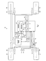
- FIG. 1 is a schematic view showing an example of a schematic configuration of a vehicle according to the embodiment.
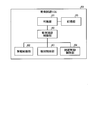
- FIG. 2 is a block diagram showing an example of a functional configuration of the collision avoidance ECU according to the present embodiment.
- FIG. 3 is a flowchart showing an example of the procedure of the process of executing the collision avoidance function of the present embodiment.
- FIG. 4 is a schematic view showing an example of a state in which the preceding vehicle is overtaken in the present embodiment.
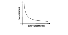
- FIG. 5 is a diagram showing an example of the relationship between the collision prediction time and the lateral acceleration necessary for collision avoidance in the present embodiment.
- FIG. 6 is a flowchart showing an example of the procedure of the determination processing of prohibition / end of the collision avoidance function operation according to the present embodiment.
- FIG. 7 is a diagram showing the relationship between the degree of deceleration due to the avoidance braking and the turning parameter in the present embodiment.
- FIG. 1 is a schematic view showing an example of a schematic configuration of a vehicle according to the embodiment.
- the vehicle 100 may be, for example, an automobile (internal combustion engine automobile) whose drive source is an internal combustion engine (engine 20), or an automobile (motor, not shown) It may be an electric car, a fuel cell car, etc.), or may be a car (hybrid car) using both of them as a driving source.
- the vehicle 100 can mount various transmissions, and can mount various devices (systems, components, etc.) necessary for driving an internal combustion engine or a motor.
- the system, number, layout, and the like of devices related to driving of the wheels in the vehicle can be set variously.
- the vehicle 100 is a four-wheeled vehicle (four-wheeled vehicle), and has two left and right front wheels FL and FR and two left and right rear wheels RL and RR.
- the front of the vehicle front-rear direction (arrow FB) is the left side.
- the vehicle 100 includes an engine 20, a brake control unit 30, an imaging device 51, a radar device 52, a brake switch 42, an accelerator pedal stroke sensor 44, and an acceleration sensor 43. , A steering system 50, a steering angle sensor 45, and a control device 40.
- Vehicle 100 also includes wheel cylinders Wfr and Wfl and wheel speed sensors 41fr and 41fl corresponding to the two front wheels FR and FL, respectively. Further, wheel cylinders Wrr and Wrl and wheel speed sensors 41rr and 41rl are provided corresponding to the two rear wheels RR and RL, respectively. Note that, hereinafter, the wheel speed sensors 41fr, 41fl, 41rr, and 41rl will be collectively referred to as "wheel speed sensors 41". When the wheel cylinders Wfr, Wfl, Wrr, and Wrl are collectively referred to, they are referred to as "wheel cylinders W”.
- vehicle 100 includes basic components as vehicle 100 in addition to FIG. 1, only the configuration related to vehicle 100 and the control related to the configuration will be described here.
- the imaging device 51 is, for example, a digital camera that incorporates an imaging element such as a charge coupled device (CCD) or a CMOS image sensor (CIS).
- the imaging device 51 can output image data (moving image data, frame data) at a predetermined frame rate.
- the imaging device 51 is, for example, located at an end (an end in a plan view) of a front side (a front side in the vehicle longitudinal direction) of a vehicle body (not shown). Then, the imaging device 51 outputs image data including an avoidance object such as a preceding vehicle in front of the vehicle 100.
- the radar device 52 is, for example, a millimeter wave radar device.
- the radar device 52 can output distance data indicating a distance to the avoidance object such as a leading vehicle (distance distance, reference to detection distance), velocity data indicating a relative velocity (velocity) to the avoidance object, and the like.
- the control device 40 updates the measurement result of the distance between the vehicle 100 and the avoidance target such as the leading vehicle by the radar device 52 as needed (for example, at a constant time interval) and stores the result in the storage unit. The measurement result of the updated distance can be used for the calculation.
- the wheel speed sensor 41 outputs a signal having a pulse each time the wheel corresponding to each wheel speed sensor 41 rotates a predetermined angle.
- An accelerator pedal stroke sensor 44 is provided on the accelerator pedal AP, and detects an amount of depression of the accelerator pedal AP by the driver.
- the brake switch 42 is provided on the brake pedal BP, and outputs a brake operation signal indicating whether or not the driver operates the brake pedal BP. Specifically, when the brake pedal BP is operated, the brake switch 42 outputs an on (High) brake operation signal. When the brake pedal BP is not operated, the brake switch 42 outputs an off (Low) brake operation signal.
- the acceleration sensor 43 detects an acceleration (longitudinal acceleration) in the longitudinal direction of the vehicle body, and outputs a signal representing the longitudinal acceleration Gx. Further, the acceleration sensor 43 detects an acceleration (lateral acceleration) in the lateral direction of the vehicle body, and outputs a signal representing the lateral acceleration Gy.
- the lateral acceleration Gy is also called lateral G.
- the yaw rate sensor 46 detects the yaw rate of the vehicle 100.
- the yaw rate is the rate of change of the rotation angle of the vehicle 100 in the yaw direction (turning direction).
- the steering system 50 is, for example, a steering wheel or the like.
- the steering angle sensor 45 is a sensor that detects the amount of steering of the steering system 50 (steering wheel).
- the steering angle sensor 45 is configured using, for example, a hall element or the like.
- the engine 20 outputs power according to the operation of the accelerator pedal AP by the driver.
- the brake control unit 30 generates a braking force by the brake fluid pressure on each of the wheels FR, FL, RR, and RL according to a command from the brake ECU 12.
- the brake control unit 30 generates a brake fluid pressure corresponding to the operating force of the brake pedal BP, and supplies the brake fluid pressure to the wheel cylinders Wfr, Wfl, Wrr, Wrl disposed on the wheels FR, FL, RR, RL respectively. Each can be adjusted.
- the control device 40 receives signals, data, and the like from each part of the vehicle 100, and executes control of each part of the vehicle 100.
- the control device 40 mainly includes a collision avoidance ECU (Electronic Control Unit) 60, a brake ECU 12, and an engine ECU 13.
- the control device 40 is an example of a collision avoidance device.
- the engine ECU 13 is responsible for various controls of the engine 20 such as fuel injection control and intake amount adjustment control.
- the brake ECU 12 performs adjustment control of the braking torque for the host vehicle, adjustment control of the braking torque for each of the wheels FR, FL, RR, and RL, and the like.
- the brake ECU 12 detects the vehicle speed of the host vehicle and the acceleration sensor 43 based on a detection signal from at least one wheel speed sensor 41 among the wheel speed sensors 41 provided for each of the wheels FR, FL, RR, and RL. Based on the signal, it calculates the deceleration etc. of the vehicle and sends it to other ECUs.
- the “deceleration” calculated here is a positive value when the host vehicle is decelerating, and is a negative value when the host vehicle is accelerating.
- the collision avoidance ECU 60 controls the execution of the collision avoidance function. Details of the collision avoidance ECU 60 will be described later.
- Each ECU is configured as a computer, and an arithmetic processing unit (not shown) such as a central processing unit (CPU), a storage unit such as a read only memory (ROM), a random access memory (RAM), or a flash memory
- the avoidance ECU 60 includes the storage unit 65).
- the arithmetic processing unit reads a program stored (installed) in a non-volatile storage unit (for example, a ROM, a flash memory, etc.), executes arithmetic processing according to the program, and functions as each ECU.
- a non-volatile storage unit for example, a ROM, a flash memory, etc.
- the collision avoidance ECU 60 functions (operates) as each unit shown in FIG. 2 described later.
- the storage unit may store data (tables (data groups), functions, and the like) used in various calculations related to control, calculation results (including values during calculation), and the like.
- the structure of the vehicle 100 mentioned above is an example to the last, and can be changed variously and implemented.
- Known devices can be used as the individual devices that configure the vehicle 100.
- each configuration of the vehicle 100 can be shared with other configurations.
- the vehicle 100 can include a sonar device to detect an avoidance object.
- FIG. 2 is a block diagram showing an example of a functional configuration of the collision avoidance ECU 60 of the present embodiment.
- the collision avoidance ECU 60 according to the present embodiment, as shown in FIG. 2 by cooperation of hardware and software (program), notifies the determination unit 61, the collision avoidance control unit 66, the alarm control unit 62, and notification. It can function (operate) as the control unit 63 and the avoidance braking control unit 64. That is, the program may include, as an example, a module corresponding to each block shown in FIG. 2 excluding the storage unit 65.
- the alarm control unit 62, the notification control unit 63, and the avoidance braking control unit 64 are an example of a collision avoidance execution unit.
- the storage unit 65 stores various threshold values and various flags described later.
- the collision avoidance control unit 66 controls the operation of the collision avoidance function.
- the collision avoidance function is a function of avoiding a collision with the preceding vehicle or the like by maintaining the relative distance between the preceding vehicle or the like which is the avoidance object and the host vehicle at a constant distance.
- the collision avoidance function includes avoidance braking, notification, and alarm.
- the avoidance braking is also referred to as automatic braking, and is to brake the vehicle 100 by the brake ECU 12 and the brake control unit 30 in order to maintain the relative distance between the preceding vehicle or the like and the host vehicle 100.
- the notification is an output from the speaker (not shown) provided in front of the driver's seat, etc., for effecting the avoidance braking.
- the alarm is an output from the speaker (not shown) to the effect that the avoidance braking should be operated.
- the notification and the alarm have different output sounds.
- FIG. 3 is a flowchart showing a procedure of execution processing of the collision avoidance function of the present embodiment.
- the collision avoidance control unit 66 inputs a collision prediction time TTC (Time To Collision) which is a prediction time until the collision with the preceding vehicle calculated by the judgment unit 61 (S11).
- TTC Time To Collision
- the determination unit 61 can calculate the collision prediction time TTC by equation (2) based on the following equation of motion (1).
- V AB is the relative speed of the host vehicle to the preceding vehicle.
- X AB is a relative distance from the host vehicle to the preceding vehicle.
- ⁇ AB is the relative acceleration of the vehicle relative to the preceding vehicle.
- the determination unit 61 calculates V AB based on the detection result of the wheel speed sensor 41, calculates ⁇ AB based on the detection result of the acceleration sensor 43, and calculates X AB based on the detection result of the radar device 52. Can.
- the collision avoidance control unit 66 calculates t which is the collision prediction time TTC according to the following equation.
- the collision avoidance control unit 66 determines whether the inputted collision prediction time TTC is equal to or less than a predetermined avoidance braking threshold (S12).
- the collision avoidance control unit 66 sends a command to the effect of the avoidance braking to the avoidance braking control unit 64, and the avoidance braking is performed. Is activated (S13). That is, in response to the command, the avoidance braking control unit 64 instructs the brake ECU 12 to perform braking, whereby the brake control unit 30 performs the braking.
- the collision avoidance control unit 66 determines whether the collision prediction time TTC is less than or equal to a predetermined notification threshold (S14).
- the notification threshold is a value smaller than the avoidance braking threshold. Then, if the collision prediction time TTC is equal to or less than the notification threshold (S14: Yes), the collision avoidance control unit 66 sends a command to the notification control unit 63 to the effect of the notification operation to activate the notification. (S15). That is, the notification control unit 63 causes the speaker to output that the avoidance braking is performed.
- the collision avoidance control unit 66 determines whether the collision prediction time TTC is less than or equal to a predetermined alarm threshold (S16).
- the warning threshold is a value smaller than the notification threshold.
- the collision avoidance control unit 66 sends a command to the alarm control unit 62 to the effect that the alarm is activated to activate the alarm. (S17). That is, the alarm control unit 62 causes the speaker to output that the avoidance braking should be performed.
- the collision avoidance control unit 66 determines whether the alarm / notification / avoidance braking is continued (step S18).
- the alarm / notification / avoidance braking continuation determination process is performed to determine whether to continue each control of alarming, notification, and avoidance braking when the collision predicted time TTC increases due to deceleration of the host vehicle or progress of a preceding vehicle. It is.
- the collision avoidance control unit 66 performs a determination process of inhibition / termination of the collision avoidance function operation (S19).
- This determination process is a process of determining whether to inhibit or end the operation of the collision avoidance function of warning, notification, and avoidance braking based on a turning parameter related to turning of the vehicle 100.
- the turning parameters there are a lateral acceleration Gy (lateral G) at the time of turning of the vehicle 100, a yaw rate, a derivative value of the lateral acceleration, and the like, but it is not limited thereto.
- the determination unit 61 determines whether a collision can be avoided between the vehicle 100 and an avoidance target such as a preceding vehicle. Specifically, the vehicle 100 turns as the driver performs a steering operation with the steering system 50 in an attempt to avoid a collision with an avoidance target such as a preceding vehicle. At this time, there is a lateral acceleration Gy (or yaw rate) as a turning parameter which is actually generated by turning of the vehicle 100. The determination unit 61 determines whether the collision with the object to be avoided can be avoided by determining whether the lateral acceleration Gy (or the yaw rate) is equal to or more than a predetermined first threshold. Here, the lateral acceleration Gy is detected by the acceleration sensor 43, and the yaw rate is detected by the yaw rate sensor 46. In addition, a derivative value of lateral acceleration may be used as the turning parameter.
- the collision avoidance control unit 66 determines that a collision with the object to be avoided can be avoided, and the collision avoidance function (alarm, notification, avoidance braking) Control to prohibit or terminate the operation of. That is, in this case, the collision avoidance control unit 66 does not send an operation command to the alarm control unit 62, the notification control unit 63, and the avoidance braking control unit 64 regardless of the value of the collision prediction time TTC.
- FIG. 4 is a schematic view showing an example of a state in which the preceding vehicle is overtaken in the present embodiment.
- the collision prediction time TTC In order to pass or pass through the preceding vehicle 501 while the host vehicle 100 is traveling, when the driver steps on the accelerator pedal AP, the distance between the preceding vehicle 501 and the preceding vehicle 501 becomes short, and the collision prediction time TTC also decreases. If the collision avoidance function (alarm / notification / avoidance braking) is not performed, a region 503 where it is impossible to avoid a collision with the preceding vehicle 501 is entered. That is, the collision prediction time TTC becomes equal to or less than the threshold value, and the collision avoidance function is activated. Even when the steering operation is performed, the passing or passing of the leading vehicle 501 intended by the driver is inhibited.
- the collision avoidance control unit 66 does not activate the collision avoidance function (alarm / notification / avoidance braking), and enables passing and passing of the preceding vehicle.
- the determination as to whether or not the turning is sufficient to avoid the collision may be made based on the steering amount by the steering operation.
- the steering amount detected by the steering operation is a steering amount sufficient for collision avoidance during normal traveling, the path of the vehicle 100 is not sufficiently changed.
- the vehicle is traveling on a road surface with a low coefficient of friction such as a road surface or a snowy road during rainfall, or when the vehicle 100 is fitted with a temper tire (spare tire) thinner than a normal tire, etc. This is when the operation is performed.
- the steering amount detected by the steering angle sensor 45 by the steering operation under such conditions is, for example, a steering amount sufficient for collision avoidance during normal traveling such as a dry asphalt road surface.
- the route of the vehicle 100 may not be sufficiently changed.
- it is determined that the collision can be avoided from the detected steering amount so the control of the avoidance braking is ended, and as a result, it is difficult to avoid the collision with the preceding vehicle or the like. There is.
- the collision avoidance control unit 66 does not determine whether the turning is sufficient to avoid the collision based on the steering amount by the steering operation, but the actual turning parameters at the turning of the vehicle 100. It is determined whether or not the turning is sufficient to avoid the collision, that is, the operation of the collision avoidance and its termination / inhibition.
- the collision avoidance control unit 66 sets the turning parameter reflecting such actual turning condition of the vehicle and the predetermined first threshold. In comparison, by determining whether or not turning is sufficient to avoid a collision, the operation of collision avoidance and its termination / inhibition are realized more reliably.
- the first threshold is determined according to the estimated collision time TTC of the vehicle 100 with respect to an avoidance target such as a preceding vehicle.
- FIG. 5 is a diagram showing an example of the relationship between the collision prediction time TTC and the lateral acceleration necessary for collision avoidance in the present embodiment.
- the horizontal axis indicates the collision predicted time TTC of the vehicle 100 with respect to the avoidance target
- the vertical axis indicates the lateral acceleration G yth required for collision avoidance.
- the lateral acceleration G yth corresponding to the collision prediction time TTC means a lateral acceleration Gy at which the lateral movement amount of the host vehicle 100 can be expected to avoid collision with respect to the lateral width of the avoidance object.
- the relationship between the collision prediction time TTC and the lateral acceleration G yth necessary for collision avoidance is stored in advance in the storage unit 65 as a correspondence table.
- the determination unit 61 of the present embodiment is based on the relative velocity V AB , the relative distance X AB , and the relative acceleration ⁇ AB with respect to the preceding vehicle calculated from detection signals from the radar device 52, the acceleration sensor 43, and the wheel speed sensor 41.
- the collision predicted time TTC is calculated, and the lateral acceleration Gyt corresponding to the collision predicted time TTC is determined as a first threshold value with reference to the correspondence table stored in the storage unit 65, and the lateral acceleration Gy of the vehicle 100 is determined. Compare with.
- the determination unit 61 determines the presence or absence of the clear cancellation intention by the driver based on the steering operation of the driver while the collision avoidance function is activated. Specifically, the determination unit 61 determines whether the steering speed is equal to or higher than a predetermined second threshold value by the steering operation of the steering system 50 by the driver. This means that when the steering speed is equal to or higher than the predetermined second threshold value, the steering operation is performed sharply and sharply unlike the normal operation, and in such a case, the determination unit 61 It is determined that there is a clear intention to cancel the operation of the collision avoidance function.
- the collision avoidance control unit 66 determines that there is a clear cancellation intention when the steering speed is equal to or higher than the predetermined second threshold by the determination unit 61 during operation of the collision avoidance function, and activates the collision avoidance function. finish.
- the collision avoidance control unit 66 When the collision avoidance control unit 66 activates the collision avoidance function (alarm, notification, avoidance braking), it stores in the storage unit 65 information on which collision avoidance function, that is, the warning, notification, and avoidance braking is activated. Save as a flag.
- the determination unit 61 determines whether or not the avoidance braking is in operation with reference to the flag of the storage unit 65.
- a collision avoidance function (alarm, notification, avoidance braking) operates in a scene where the driver does not feel necessity.
- the minimum value of the first threshold is set in consideration of errors and noise, when the vehicle 100 is very slow, the lateral acceleration Gy, the yaw rate, etc. are obtained even if the driver performs the minimum avoidable steering operation.
- the turning parameter of is small and may not reach the first threshold as expected.
- the driver when the driver recognizes such a special situation such as a failure of the vehicle 100 by an alarm, a notification or the like, the driver normally performs the steering operation in order to forcibly stop the collision avoidance function. In doing so at different speeds, indicates a clear cancellation intention of the collision avoidance function during operation. As a result, the steering speed becomes equal to or higher than the second threshold, and the determination unit 61 determines this and the operation of the collision avoidance function can be canceled under the above-mentioned special situation.
- FIG. 6 is a flowchart showing an example of the procedure of the determination processing of prohibition / end of the collision avoidance function operation according to the present embodiment.
- the process shown in FIG. 6 is separately executed in each case where the alarm is activated in S17, when the avoidance braking is activated in S13 of FIG. 3, the notification is activated in S15.
- the turning parameter is the lateral acceleration Gy is shown, but the same applies to the case where the turning parameter is the yaw rate and the derivative value of the lateral acceleration.
- the determination unit 61 calculates the collision prediction time TTC based on the relative velocity V AB , the relative distance X AB , and the relative acceleration ⁇ AB as described above (S34), and determines a first threshold (S30). Then, when the steering operation by the driver is performed, the determination unit 61 determines whether or not the lateral acceleration Gy when the host vehicle 100 is turning is equal to or greater than the first threshold (S31). When the lateral acceleration is equal to or greater than the first threshold (S31: Yes), the collision avoidance control unit 66 prohibits and terminates the operation of the alarm and the notification, and prohibits the operation of the avoidance braking (S33).
- FIG. 7 is a diagram showing the relationship between the degree of deceleration due to the avoidance braking and the turning parameter in the present embodiment.
- FIG. 7A shows the temporal change of the deceleration due to the avoidance braking.
- FIG. 7 (b) shows the temporal change of the lateral acceleration Gy, and
- FIG. 7 (c) shows the temporal change of the differential value of the lateral acceleration Gy.
- the lateral acceleration Gy of the vehicle 100 has a first threshold value.
- the operation of the avoidance braking is finished, and the deceleration is thereby reduced.
- the differential value dGy / dt of the lateral acceleration Gy of the vehicle 100 becomes equal to or more than the first threshold, the operation of the avoidance braking ends as shown in FIG. 7 (a). And this will reduce the deceleration.
- the collision avoidance control unit 66 continues without inhibiting / terminating the operation of the collision avoidance function.
- the determination unit 61 determines whether there is a clear intention to cancel the collision avoidance function during operation by determining whether the steering speed by the driver's steering operation is equal to or higher than the second threshold (S32) ).
- the determination unit 61 sets a value at which the steering speed of the steering operation by the steering operation is higher than the normal value as the second threshold.
- the determination unit 61 determines that there is a clear cancellation intention by the driver's steering operation. Then, the collision avoidance control unit 66 prohibits and terminates the operation of the alarm and the notification, and prohibits the operation of the avoidance braking (S33).
- the determination unit 61 determines that there is no clear cancellation intention by the driver's steering operation. Then, the collision avoidance control unit 66 continues without prohibiting or ending the operation of the collision avoidance function (alarm, notification, avoidance braking). This is because, at the timing when the collision avoidance function is activated, the collision avoidance by the steering operation is physically difficult to avoid, and the vehicle 100 reaches a region where the collision avoidance function has to be activated and the risk is increased. It is because it is a state. Then, the process ends.
- the driver when the driver performs the steering operation of the steering system 50 in order to avoid the collision with the avoidance object, it is determined whether the turning is sufficient for collision avoidance by the steering amount by the steering operation. Rather, it is determined whether or not turning is sufficient for collision avoidance based on a turning parameter actually generated by turning of the vehicle 100 by a steering operation, that is, inhibition / termination of the operation of the collision avoidance function. For this reason, as compared with determining whether or not a turn is sufficient for collision avoidance based on the steering amount by the steering operation, it is a turn that is sufficient for collision avoidance, reflecting the influence of the road surface condition, the condition of tires, etc.
- the collision avoidance operation and its termination can be performed more reliably. Thus, according to the present embodiment, it is possible to more reliably avoid collisions.
Landscapes
- Engineering & Computer Science (AREA)
- Transportation (AREA)
- Mechanical Engineering (AREA)
- Automation & Control Theory (AREA)
- Chemical & Material Sciences (AREA)
- Combustion & Propulsion (AREA)
- Physics & Mathematics (AREA)
- General Physics & Mathematics (AREA)
- Human Computer Interaction (AREA)
- Regulating Braking Force (AREA)
- Control Of Driving Devices And Active Controlling Of Vehicle (AREA)
Abstract
衝突回避装置は、例えば、回避対象物との衝突を回避するための衝突回避機能を作動可能な衝突回避実行部と、ドライバーによりステアリング操作が行われた場合に、ステアリング操作による旋回に関する旋回パラメータに基づいて、回避対象物と衝突が回避可能か否かを判断する判断部と、回避対象物と衝突が回避可能と判断された場合には、衝突回避機能の作動を禁止または終了する衝突回避制御部と、を備える。
Description
本発明は、衝突回避装置に関する。
近年、自車両と自車両の進行方向前側に存在する先行車両との車間距離が一定距離以下になった場合に自動ブレーキ等の回避制動を行い、先行車両との衝突を回避する衝突回避装置が知られている。このような従来の衝突回避装置としては、例えば、回避制動の作動中に、ドライバーによるステアリング操作があった場合に回避制動の制御を終了して、不要な回避制動の介入を防止する技術が知られている。
しかしながら、このような従来の衝突回避装置では、例えば、走行する路面の状況やタイヤの状態等によっては、ステアリング操作により検知される操舵量が、通常走行時において衝突回避に充分な操舵量であっても、車両の進路が充分変更されない場合がある。このような場合には、検知される操舵量からは衝突回避可能と判断されるため、回避制動の制御が終了してしまい、その結果、先行車両等との衝突を回避することが困難な場合がある。
そこで、本発明の課題の一つは、衝突回避機能を備えた車両において、より確実に衝突回避を行うことができる衝突回避装置を提供することである。
本発明の衝突回避装置は、回避対象物との衝突を回避するための衝突回避機能を作動可能な衝突回避実行部と、ドライバーによりステアリング操作が行われた場合に、前記ステアリング操作による旋回に関する旋回パラメータに基づいて、前記回避対象物と衝突が回避可能か否かを判断する判断部と、前記回避対象物と衝突が回避可能と判断された場合には、前記衝突回避機能の作動を禁止または終了する衝突回避制御部と、を備える。
また、本発明の衝突回避装置において、前記判断部は、前記旋回パラメータとしての横加速度またはヨーレートが第1閾値以上であるか否かを判断することにより、前記回避対象物と衝突が回避可能か否かを判断し、前記衝突回避制御部は、自車両の前記横加速度または前記ヨーレートが前記第1閾値以上である場合に、前記衝突回避機能の作動を禁止または終了する。
また、本発明の衝突回避装置において、前記判断部は、前記衝突回避機能の作動中に、ドライバーのステアリング操作に基づいて、前記ドライバーによるキャンセル意思の有無を判断し、前記衝突回避制御部は、前記衝突回避機能の作動中に、前記キャンセル意思があると判断された場合には、前記衝突回避機能の作動を終了する。
また、本発明の衝突回避装置において、前記判断部は、前記ステアリング操作による操舵速度が第2閾値以上であるか否かにより、前記キャンセル意思の有無を判断し、前記衝突回避制御部は、前記操舵速度が第2閾値以上である場合には、前記衝突回避機能の作動を終了する。
以下、本発明の例示的な実施形態が開示される。以下に示される実施形態の構成、ならびに当該構成によってもたらされる作用および結果(効果)は、一例である。本発明は、以下の実施形態に開示される構成以外によっても実現可能である。また、本発明によれば、構成によって得られる種々の効果(派生的な効果も含む)のうち少なくとも一つを得ることが可能である。
図1は、実施形態にかかる車両の概略構成の一例を示す模式図である。本実施形態では、車両100は、例えば、内燃機関(エンジン20)を駆動源とする自動車(内燃機関自動車)であってもよいし、電動機(モータ、図示されず)を駆動源とする自動車(電気自動車、燃料電池自動車等)であってもよいし、それらの双方を駆動源とする自動車(ハイブリッド自動車)であってもよい。また、車両100は、種々の変速装置を搭載することができるし、内燃機関や電動機を駆動するのに必要な種々の装置(システム、部品等)を搭載することができる。また、車両における車輪の駆動に関わる装置の方式や、数、レイアウト等は、種々に設定することができる。また、本実施形態では、一例として、車両100は、四輪車(四輪自動車)であり、左右二つの前輪FL,FRと、左右二つの後輪RL,RRとを有する。なお、図1では、車両前後方向(矢印FB)の前方は、左側である。
本実施形態の車両100は、図1に示すように、エンジン20と、ブレーキ制御部30と、撮像装置51と、レーダ装置52と、ブレーキスイッチ42と、アクセルペダルストロークセンサ44と、加速度センサ43と、操舵システム50と、舵角センサ45と、制御装置40とを備えている。
また、車両100は、二つの前輪FR,FLのそれぞれに対応して、ホイールシリンダWfr,Wflと車輪速度センサ41fr,41flとを備える。また、二つの後輪RR,RLのそれぞれに対応して、ホイールシリンダWrr,Wrlと車輪速度センサ41rr,41rlとを備える。なお、これ以降、車輪速度センサ41fr,41fl,41rr,41rlを総称する場合には、「車輪速度センサ41」と呼ぶ。また、ホイールシリンダWfr,Wfl,Wrr,Wrlを総称する場合には、「ホイールシリンダW」と呼ぶ。
なお、車両100は、図1の他にも車両100としての基本的な構成要素を備えているが、ここでは、車両100に関わる構成ならびに当該構成に関わる制御についてのみ、説明される。
撮像装置51は、例えば、CCD(Charge Coupled Device)やCIS(CMOS Image Sensor)等の撮像素子を内蔵するデジタルカメラである。撮像装置51は、所定のフレームレートで画像データ(動画データ、フレームデータ)を出力することができる。本実施形態では、撮像装置51は、例えば、車体(不図示)の前側(車両前後方向の前方側)の端部(平面視での端部)に位置され、フロントバンパー等に設けられうる。そして、撮像装置51は、車両100の前方の先行車両等の回避対象物を含む画像データを出力する。
レーダ装置52は、例えば、ミリ波レーダ装置である。レーダ装置52は、先行車両等の回避対象物までの距離(離間距離、検出距離参照)を示す距離データや、回避対象物との相対速度(速度)を示す速度データ等を出力することができる。なお、制御装置40は、レーダ装置52による車両100と先行車両等の回避対象物との間の距離の測定結果を随時(例えば、一定の時間間隔等で)更新して記憶部に記憶する。演算には更新された距離の測定結果を利用することができる。
車輪速度センサ41は、各車輪速度センサ41に対応する車輪が所定角度回転する毎にパルスを有する信号を出力する。
アクセルペダルストロークセンサ44は、アクセルペダルAPに設けられ、ドライバーによるアクセルペダルAPの踏込み量を検知する。ブレーキスイッチ42は、ブレーキペダルBPに設けられ、ドライバーによるブレーキペダルBPの操作の有無を示すブレーキ操作信号を出力する。具体的には、ブレーキペダルBPが操作されている場合には、ブレーキスイッチ42は、オン(High)のブレーキ操作信号を出力する。ブレーキペダルBPが操作されていない場合には、ブレーキスイッチ42は、オフ(Low)のブレーキ操作信号を出力する。
加速度センサ43は、車体前後方向の加速度(前後加速度)を検出し、前後加速度Gxを表す信号を出力する。また、加速度センサ43は、車体横方向の加速度(横加速度)を検出し、横加速度Gyを表す信号を出力する。ここで、横加速度Gyは、横Gとも呼ばれる。
ヨーレートセンサ46は、車両100のヨーレートを検出する。ここで、ヨーレートとは、車両100のヨー方向(旋回方向)への回転角の変化速度である。
操舵システム50は、例えば、ステアリングホイール等である。舵角センサ45は、操舵システム50(ステアリングホイール)の操舵量を検出するセンサである。舵角センサ45は、例えば、ホール素子などを用いて構成される。
エンジン20は、ドライバーによるアクセルペダルAPの操作に応じた動力を出力する。ブレーキ制御部30は、ブレーキECU12からの指令により、各車輪FR,FL,RR,RLにブレーキ液圧によるブレーキ力を発生させる。ブレーキ制御部30は、ブレーキペダルBPの操作力に応じたブレーキ液圧を発生し、車輪FR,FL,RR,RLにそれぞれ配置されたホイールシリンダWfr,Wfl,Wrr,Wrlに供給するブレーキ液圧をそれぞれ調整可能となっている。
制御装置40は、車両100の各部から信号やデータ等を受け取るとともに、車両100の各部の制御を実行する。制御装置40は、図1に示すように、衝突回避ECU(Electronic Control Unit)60と、ブレーキECU12と、エンジンECU13とを主に備えている。本実施形態では、制御装置40は、衝突回避装置の一例である。
エンジンECU13は、燃料の噴射制御及び吸気量の調整制御などのエンジン20の各種制御を司る。
ブレーキECU12は、自車両に対する制動トルクの調整制御、及び車輪FR,FL,RR,RL毎の制動トルクの調整制御などを司る。ブレーキECU12は、車輪FR,FL,RR,RL毎に設けられた各車輪速度センサ41のうち少なくとも一つの車輪速度センサ41からの検出信号に基づき自車両の車体速度と、加速度センサ43からの検出信号に基づき自車両の減速度等を算出し、他のECUへ送出する。なお、ここで算出される「減速度」は、自車両が減速しているときには正の値となり、自車両が加速しているときには負の値となる。
衝突回避ECU60は、衝突回避機能の実行を制御する。衝突回避ECU60の詳細については後述する。各ECUは、コンピュータとして構成されており、CPU(Central Processing Unit)等の演算処理部(不図示)と、ROM(Read Only Memory)やRAM(Random Access Memory)、フラッシュメモリ等の記憶部(衝突回避ECU60では記憶部65)を備えている。
演算処理部は、不揮発性の記憶部(例えばROMや、フラッシュメモリ等)に記憶された(インストールされた)プログラムを読み出し、当該プログラムにしたがって演算処理を実行し、各ECUとして機能する。特に、衝突回避ECU60は、後述する図2に示された各部として機能(動作)する。また、記憶部には、制御に関わる各種演算で用いられるデータ(テーブル(データ群)や、関数等)や、演算結果(演算途中の値も含む)等が記憶されうる。
なお、上述した車両100の構成はあくまで一例であって、種々に変更して実施することができる。車両100を構成する個々の装置としては、公知の装置を用いることができる。また、車両100の各構成は、他の構成と共用することができる。また、車両100は、回避対象物を検出するためにソナー装置を備えることができる。
次に、衝突回避ECU60の詳細について説明する。図2は、本実施形態の衝突回避ECU60の機能的構成の一例を示すブロック図である。本実施形態の衝突回避ECU60は、ハードウエアとソフトウエア(プログラム)との協働により、図2に示されるように、判断部61と、衝突回避制御部66と、警報制御部62と、報知制御部63と、回避制動制御部64として機能(動作)することができる。すなわち、プログラムには、一例としては、図2に示される、記憶部65を除く各ブロック、に対応したモジュールが含まれうる。ここで、警報制御部62、報知制御部63、回避制動制御部64は衝突回避実行部の一例である。記憶部65には、後述する各種の閾値、各種フラグが保存される。
衝突回避制御部66は衝突回避機能の作動を制御する。衝突回避機能は、回避対象物である先行車両等と自車両との相対距離を一定距離に維持して先行車両等との衝突を回避する機能である。衝突回避機能として、具体的には、回避制動、報知、警報がある。回避制動は、自動ブレーキともいい、先行車両等と自車両100との相対距離を維持するために、ブレーキECU12、ブレーキ制御部30により車両100に制動をかけることである。報知は、運転席の前方等に設けられたスピーカ(不図示)から、回避制動を作動させる旨の出力である。警報は、上記スピーカ(不図示)から、回避制動を作動させるべき旨の出力である。報知と警報とは、出力音が異なる。
それぞれの衝突回避機能の処理は以下のように行われる。図3は、本実施形態の衝突回避機能の実行処理の手順を示すフローチャートである。
まず、衝突回避制御部66は、判断部61で算出した先行車両と衝突するまでの予測時間である衝突予測時間TTC(Time To Collision)を入力する(S11)。ここで、判断部61は、衝突予測時間TTCを、次の運動方程式(1)式に基づく(2)式によって算出することができる。

ここで、tは衝突予測時間TTCである。VABは自車両の先行車両に対する相対速度である。XABは自車両から先行車両までの相対距離である。αABは自車両の先行車両に対する相対加速度である。なお、判断部61は、VABを車輪速度センサ41の検知結果に基づき算出し、αABを加速度センサ43の検知結果に基づき算出し、XABをレーダ装置52の検知結果に基づき算出することができる。
なお、(2)式においてtの値が負となる場合やルート内の値が負となる場合には、衝突回避制御部66は、衝突予測時間TTCであるtを次式で算出する。
t=XAB/VAB
次に、衝突回避制御部66は、入力した衝突予測時間TTCが所定の回避制動閾値以下であるか否かを判断する(S12)。そして、衝突予測時間TTCが回避制動閾値以下である場合には(S12:Yes)、衝突回避制御部66は、回避制動制御部64に対し回避制動の作動の旨の指令を送出し、回避制動を作動させる(S13)。すなわち、回避制動制御部64は、当該指令を受けて、ブレーキECU12に対して制動を指示し、これにより、ブレーキ制御部30による制動が行われる。
衝突予測時間TTCが回避制動閾値より大きい場合には(S12:No)、衝突回避制御部66は、衝突予測時間TTCが所定の報知閾値以下であるか否かを判断する(S14)。ここで、報知閾値は、回避制動閾値より小さい値である。そして、衝突予測時間TTCが報知閾値以下である場合には(S14:Yes)、衝突回避制御部66は、報知制御部63に対し報知の作動の旨の指令を送出して、報知を作動させる(S15)。すなわち、報知制御部63が回避制動を行う旨をスピーカから出力させる。
衝突予測時間TTCが報知閾値より大きい場合には(S14:No)、衝突回避制御部66は、衝突予測時間TTCが所定の警報閾値以下であるか否かを判断する(S16)。ここで、警報閾値は、報知閾値より小さい値である。そして、衝突予測時間TTCが警報閾値以下である場合には(S16:Yes)、衝突回避制御部66は、警報制御部62に対し警報の作動の旨の指令を送出して、警報を作動させる(S17)。すなわち、警報制御部62が回避制動を行うべき旨をスピーカから出力させる。
衝突予測時間TTCが警報閾値より大きい場合には(S16:No)、衝突回避制御部66は、警報・報知・回避制動の継続判定を行う(ステップS18)。警報・報知・回避制動の継続判定は、自車両の減速や先行車両の進行等により衝突予測時間TTCが増加した場合、警報、報知、回避制動の各制御を継続するか否かを判断する処理である。
そして、警報・報知・回避制動の継続判定、または警報、報知、回避制動の各作動の後、衝突回避制御部66は、衝突回避機能作動の禁止・終了の判定処理を行う(S19)。この判定処理は、車両100の旋回に関する旋回パラメータに基づいて、警報、報知、回避制動の衝突回避機能の作動を禁止または終了するか否かを判定する処理である。ここで、旋回パラメータとしては、車両100の旋回時の横加速度Gy(横G)やヨーレート、横加速度の微分値等があるがこれらに限定されるものではない。
以下、本実施形態の衝突回避機能作動の禁止・終了の判定について説明する。
図2に戻り、判断部61は、車両100と先行車両等の回避対象物と衝突が回避可能か否かを判断する。具体的には、ドライバーが先行車両等の回避対象物との衝突を回避しようとして操舵システム50でステアリング操作を行うことにより、車両100が旋回する。このとき、車両100に旋回により実際に発生する旋回パラメータとしての横加速度Gy(またはヨーレート)がある。判断部61は、この横加速度Gy(またはヨーレート)が所定の第1閾値以上であるか否かを判断することにより、回避対象物と衝突が回避可能か否かを判断する。ここで、横加速度Gyは加速度センサ43で検知され、ヨーレートはヨーレートセンサ46で検知される。また、旋回パラメータとして、この他、横加速度の微分値を用いてもよい。
図2に戻り、判断部61は、車両100と先行車両等の回避対象物と衝突が回避可能か否かを判断する。具体的には、ドライバーが先行車両等の回避対象物との衝突を回避しようとして操舵システム50でステアリング操作を行うことにより、車両100が旋回する。このとき、車両100に旋回により実際に発生する旋回パラメータとしての横加速度Gy(またはヨーレート)がある。判断部61は、この横加速度Gy(またはヨーレート)が所定の第1閾値以上であるか否かを判断することにより、回避対象物と衝突が回避可能か否かを判断する。ここで、横加速度Gyは加速度センサ43で検知され、ヨーレートはヨーレートセンサ46で検知される。また、旋回パラメータとして、この他、横加速度の微分値を用いてもよい。
衝突回避制御部66は、車両100の横加速度Gy(またはヨーレート)が第1閾値以上である場合には、回避対象物と衝突が回避可能と判断し、衝突回避機能(警報、報知、回避制動)の作動を禁止または終了する制御を行う。すなわち、この場合、衝突回避制御部66は、衝突予測時間TTCの値にかかわらず、警報制御部62、報知制御部63、回避制動制御部64に対して作動の指令を送出しない。
図4は、本実施形態における先行車両の追い越しを行う状態の一例を示す模式図である。自車両100が走行中に先行車両501の追い越しやすり抜けを行うため、ドライバーがアクセルペダルAPの踏み込みを行った場合、先行車両501との車間距離が短くなり、衝突予測時間TTCも減少するため、衝突回避機能(警報/報知/回避制動)を行わなければ先行車両501と衝突を回避することが不可能な領域503に入る。すなわち、衝突予測時間TTCが閾値以下となり、衝突回避機能が作動してしまい、ステアリング操作を行った場合でも、ドライバーの意図である先行車両501の追い越しやすり抜けを阻害してしまう。
このため、本実施形態では、ステアリング操作による自車両100の旋回時の横加速度Gy(またはヨーレート)が第1閾値以上である場合に、衝突を回避するために充分な旋回であると判断して、衝突回避制御部66は、衝突回避機能(警報/報知/回避制動)を作動させないこととし、先行車両の追い越しやすり抜けを可能としているのである。
ここで、衝突を回避するために充分な旋回であるか否かの判断を、ステアリング操作による操舵量で判断することも考えられる。しかしながら、走行する路面の状況やタイヤの状態等によっては、ステアリング操作により検知される操舵量が、通常走行時において衝突回避に充分な操舵量であっても、車両100の進路が充分変更されない場合がある。例えば、降雨時の路面や雪道等の摩擦係数が低い路面を車両が走行している場合や、車両100に通常タイヤより細いテンパータイヤ(スペアタイヤ)等が装着された場合等にドライバーがステアリング操作を行った場合である。
すなわち、このような状況下におけるステアリング操作により舵角センサ45で検知される操舵量が、例えば、乾燥したアスファルトの路面等の通常の走行時においては衝突回避に充分な操舵量であっても、上記状況下では、車両100の進路が充分に変更されない場合がある。このような場合には、検知される操舵量からは衝突回避可能と判断されるため、回避制動の制御が終了してしまい、その結果、先行車両等との衝突を回避することが困難な場合がある。
このような場合には、ステアリング操作により回避制動を終了せずに、回避制動の作動をさせた状態である方が好ましい。このため、本実施形態では、衝突回避制御部66は、ステアリング操作による操舵量によって衝突を回避するために充分な旋回か否かを判断するのではなく、車両100の旋回時の実際の旋回パラメータにより衝突を回避するために充分な旋回か否か、すなわち、衝突回避の作動およびその終了・禁止を判断する。
実際に発生する旋回パラメータは、路面の状況やタイヤの状態等によって変動するため、衝突回避制御部66は、このような実際の車両の旋回状態を反映した旋回パラメータと所定の第1閾値とを比較して、衝突を回避するために充分な旋回か否かを判断することで、より確実に衝突回避の作動およびその終了・禁止を実現している。
第1閾値は、先行車両等の回避対象に対する自車両100の衝突予測時間TTCに応じて定められる。図5は、本実施形態において、衝突予測時間TTCと衝突回避に必要な横加速度との関係の一例を示す図である。図5において、横軸が回避対象に対する自車両100の衝突予測時間TTCであり、縦軸が衝突回避に必要な横加速度Gythを示す。図5からわかるように、衝突予測時間TTCが大きくなる程、衝突回避に必要な横加速度Gythが小さくなる。ここで、衝突予測時間TTCに対応する横加速度Gythは、回避対象物の横幅に対して自車両100の横移動量が衝突回避が見込める値となる横加速度Gyを意味する。
このような衝突予測時間TTCと衝突回避に必要な横加速度Gythとの関係は、対応テーブルとして予め記憶部65に保存されている。本実施形態の判断部61は、レーダ装置52や、加速度センサ43、車輪速度センサ41からの検知信号から算出した先行車両との相対速度VAB、相対距離XAB、相対加速度αABに基づいて衝突予測時間TTCを算出し、記憶部65に保存された上記対応テーブルを参照して、衝突予測時間TTCに対応する横加速度Gythを第1閾値として決定して、自車両100の横加速度Gyと比較している。
また、判断部61は、衝突回避機能の作動中に、ドライバーのステアリング操作に基づいて、ドライバーによる明らかなキャンセル意思の有無を判断する。具体的には、判断部61は、ドライバーによる操舵システム50のステアリング操作により操舵速度が所定の第2閾値以上であるか否かを判断する。これは、操舵速度が所定の第2閾値以上である場合とは、ステアリング操作が通常の操作と異なり、急激に大きく行われた場合を意味し、このような場合に、判断部61は、ドライバーには衝突回避機能の作動の明らかなキャンセル意思があると判断される。
また、衝突回避制御部66は、衝突回避機能の作動中に、判断部61によって操舵速度が所定の第2閾値以上である場合、明らかなキャンセル意思があると判断し、衝突回避機能の作動を終了する。
なお、衝突回避制御部66は、衝突回避機能(警報、報知、回避制動)を作動させる場合に、いずれの衝突回避機能、すなわち警報、報知、回避制動を作動したかの情報を記憶部65にフラグとして保存しておく。判断部61は、回避制動を作動中か否かを、当該記憶部65のフラグを参照して判断する。
例えば、車両100の故障等により、実際よりも近距離に回避対象があると誤って認識した場合、ドライバが必要性を感じない場面で衝突回避機能(警報、報知、回避制動)が作動してしまう可能性がある。あるいは、第1閾値の最小値は誤差やノイズを考慮して設定されるが、車両100がごく低速の場合、ドライバーが回避可能な最小限のステアリング操作を行っても、横加速度Gyやヨーレート等の旋回パラメータが小さくて、思うように第1閾値に達しない可能性がある。
本実施形態では、このような車両100の故障等の特殊な状況を警報、報知等により、ドライバーが認識した場合に、衝突回避機能を強制的に停止するために、ドライバーはステアリング操作を通常とは異なった速さで大きく行って、作動中の衝突回避機能の明らかなキャンセル意思を示す。これにより、操舵速度が第2閾値以上となり、これを判断部61が判断して、上記特殊な状況下で衝突回避機能の作動をキャンセル可能となる。
以下、このような本実施形態の衝突回避機能作動の禁止・終了の判定(図3のS19)について、一連の流れで説明する。図6は、本実施形態の衝突回避機能作動の禁止・終了の判定処理の手順の一例を示すフローチャートである。図6に示す処理は、図3のS13で回避制動が作動した場合、S15で報知が作動した場合、S17で警報が作動した場合のそれぞれの場合において別個に実行される。また、図6に示す処理では、旋回パラメータが横加速度Gyの場合の例を示しているが、旋回パラメータがヨーレート、横加速度の微分値の場合も同様である。
まず、判断部61は、前述したように相対速度VAB、相対距離XAB、相対加速度αABに基づいて衝突予測時間TTCを算出して(S34)第1閾値を決定する(S30)。そして、ドライバーによるステアリング操作が行われた場合、判断部61は、自車両100の旋回時の横加速度Gyが第1閾値以上か否かを判断する(S31)。そして、横加速度が第1閾値以上である場合には(S31:Yes)、衝突回避制御部66は、警報、報知の作動を禁止および終了し、回避制動の作動を禁止する(S33)。
図7は、本実施形態における回避制動による減速度と旋回パラメータの関係を示す図である。図7(a)が回避制動による減速度の時間的変化を示す。図7(b)が横加速度Gyの時間的変化を示し、図7(c)が横加速度Gyの微分値の時間的変化を示す。
図7(a)に示すように、回避制動が作動して減速度が立ち上がって一定値に維持されているときに、図7(b)に示すように車両100の横加速度Gyが第1閾値以上となった時点で、回避制動の作動が終了し、これにより減速度が低下していく。また、図7(c)に示すように車両100の横加速度Gyの微分値dGy/dtが第1の閾値以上となった時点で、図7(a)に示すように回避制動の作動が終了し、これにより減速度が低下していく。
図6に戻り、S31で横加速度Gyが第1閾値未満である場合に(S31:No)、衝突回避制御部66は、衝突回避機能の作動の禁止・終了を行わず、継続する。
そして、判断部61はドライバーのステアリング操作による操舵速度が第2閾値以上であるか否かを判断することにより、作動中の衝突回避機能の明らかなキャンセル意思があるか否かを判断する(S32)。ここで、判断部61は、ステアリング操作による操舵の操舵速度が通常値より高い値を第2閾値としている。
そして、操舵速度が第2閾値以上である場合には(S32:Yes)、判断部61は、ドライバーのステアリング操作による明らかなキャンセル意思があると判断する。そして、衝突回避制御部66は、警報、報知の作動を禁止および終了し、回避制動の作動を禁止する(S33)。
一方、S32で、操舵速度が第2閾値未満である場合には(S32:No)、判断部61は、ドライバーのステアリング操作による明らかなキャンセル意思はないと判断する。そして、衝突回避制御部66は、衝突回避機能(警報、報知、回避制動)の作動の禁止および終了は行わず、続行する。これは、衝突回避機能が作動したタイミングでは、ステアリング操作による操舵による衝突回避が物理的に困難であり、かつ衝突回避機能を作動しなければならない領域まで車両100が到達して危険性が高まった状態であるためである。そして、処理は終了する。
このように本実施形態では、回避対象物との衝突を回避するためにドライバーが操舵システム50のステアリング操作を行った場合、ステアリング操作による操舵量によって衝突回避に充分な旋回か否かを判断するのではなく、ステアリング操作による車両100の旋回により実際に発生する旋回パラメータにより衝突回避に充分な旋回か否か、すなわち、衝突回避機能の作動の禁止・終了を判断している。このため、ステアリング操作による操舵量によって衝突回避に充分な旋回か否かを判断することに比べて、路面の状況やタイヤ等の状態等の影響を反映して、衝突回避に充分な旋回か否かを判断することができ、より確実に衝突回避の作動およびその終了を行うことができる。これにより、本実施形態によれば、より確実に衝突回避を行うことが可能となる。
また、本実施形態では、ドライバーがステアリング操作を、通常とは異なった速さで大きく行った場合に、作動中の衝突回避機能の作動の明らかなキャンセル意思があると判断し、回避制動等の衝突回避機能を強制的に回避する。このため、本実施形態によれば、車両100の故障等の特殊な状況下での衝突回避機能の不要な継続を防止することができる。
本発明のいくつかの実施形態を説明したが、これらの実施形態は、例として提示したものであり、発明の範囲を限定することは意図していない。これら新規な実施形態は、その他の様々な形態で実施されることが可能であり、発明の要旨を逸脱しない範囲で、種々の省略、置き換え、変更を行うことができる。これら実施形態やその変形は、発明の範囲や要旨に含まれるとともに、請求の範囲に記載された発明とその均等の範囲に含まれる。
12…ブレーキECU、13…エンジンECU、20…エンジン、30…ブレーキ制御部、40…制御装置、41(41fr,41fl,41rr,41rl)…車輪速度センサ、42…ブレーキスイッチ、43…加速度センサ、44…アクセルペダルストロークセンサ、45…舵角センサ、46…ヨーレートセンサ、60…衝突回避ECU、61…判断部、62…警報制御部、63…報知制御部、64…回避制動制御部、65…記憶部、66…衝突回避制御部、100…車両。
Claims (4)
- 衝突回避装置であって、
回避対象物との衝突を回避するための衝突回避機能を作動可能な衝突回避実行部と、
ドライバーによりステアリング操作が行われた場合に、前記ステアリング操作による旋回に関する旋回パラメータに基づいて、前記回避対象物と衝突が回避可能か否かを判断する判断部と、
前記回避対象物と衝突が回避可能と判断された場合には、前記衝突回避機能の作動を禁止または終了する衝突回避制御部と、
を備えた衝突回避装置。 - 前記判断部は、前記旋回パラメータとしての横加速度またはヨーレートが第1閾値以上であるか否かを判断することにより、前記回避対象物と衝突が回避可能か否かを判断し、
前記衝突回避制御部は、自車両の前記横加速度または前記ヨーレートが前記第1閾値以上である場合に、前記衝突回避機能の作動を禁止または終了する、
請求項1に記載の衝突回避装置。 - 前記判断部は、前記衝突回避機能の作動中に、前記ドライバーの前記ステアリング操作に基づいて、前記ドライバーによるキャンセル意思の有無を判断し、
前記衝突回避制御部は、前記衝突回避機能の作動中に、前記キャンセル意思があると判断された場合には、前記衝突回避機能の作動を終了する、
請求項1または2に記載の衝突回避装置。 - 前記判断部は、前記ステアリング操作による操舵速度が第2閾値以上であるか否かにより、前記キャンセル意思の有無を判断し、
前記衝突回避制御部は、前記操舵速度が第2閾値以上である場合には、前記衝突回避機能の作動を終了する、
請求項3に記載の衝突回避装置。
Priority Applications (3)
| Application Number | Priority Date | Filing Date | Title |
|---|---|---|---|
| EP15863698.5A EP3225472B1 (en) | 2014-11-28 | 2015-11-27 | Collision avoidance device |
| CN201580063810.4A CN107000712A (zh) | 2014-11-28 | 2015-11-27 | 避撞装置 |
| US15/529,152 US20170358209A1 (en) | 2014-11-28 | 2015-11-27 | Collision avoidance device |
Applications Claiming Priority (2)
| Application Number | Priority Date | Filing Date | Title |
|---|---|---|---|
| JP2014242296A JP6302825B2 (ja) | 2014-11-28 | 2014-11-28 | 衝突回避装置 |
| JP2014-242296 | 2014-11-28 |
Publications (1)
| Publication Number | Publication Date |
|---|---|
| WO2016084969A1 true WO2016084969A1 (ja) | 2016-06-02 |
Family
ID=56074514
Family Applications (1)
| Application Number | Title | Priority Date | Filing Date |
|---|---|---|---|
| PCT/JP2015/083508 Ceased WO2016084969A1 (ja) | 2014-11-28 | 2015-11-27 | 衝突回避装置 |
Country Status (5)
| Country | Link |
|---|---|
| US (1) | US20170358209A1 (ja) |
| EP (1) | EP3225472B1 (ja) |
| JP (1) | JP6302825B2 (ja) |
| CN (1) | CN107000712A (ja) |
| WO (1) | WO2016084969A1 (ja) |
Families Citing this family (18)
| Publication number | Priority date | Publication date | Assignee | Title |
|---|---|---|---|---|
| JP6485328B2 (ja) * | 2015-11-09 | 2019-03-20 | 株式会社デンソー | 車両の運転支援装置 |
| CN109311462B (zh) * | 2016-06-15 | 2021-03-05 | 日立汽车系统株式会社 | 车辆控制装置 |
| JP6535302B2 (ja) * | 2016-07-13 | 2019-06-26 | 株式会社Soken | 物体検知装置 |
| CN109979239A (zh) * | 2017-12-28 | 2019-07-05 | 北京百度网讯科技有限公司 | 违规车辆提醒方法、装置及设备 |
| EP3597511B1 (en) * | 2018-07-19 | 2021-03-03 | Volvo Car Corporation | Method and system for providing a steering guidance to a driver of a host vehicle |
| KR102587244B1 (ko) * | 2018-08-27 | 2023-10-06 | 현대자동차주식회사 | 자율주행 차량의 충돌 위험상황 판단 방법 |
| US11059479B2 (en) * | 2018-10-08 | 2021-07-13 | Mando Corporation | Collision avoidance apparatus and collision avoidance method |
| KR101964858B1 (ko) * | 2018-10-08 | 2019-08-13 | 주식회사 만도 | 충돌 방지 장치 및 충돌 방지 방법 |
| US11185003B2 (en) * | 2019-04-03 | 2021-11-30 | Caterpillar Inc. | Tipping avoidance system and method |
| JP7439413B2 (ja) * | 2019-08-26 | 2024-02-28 | スズキ株式会社 | 自動ブレーキ装置 |
| KR20210035523A (ko) * | 2019-09-24 | 2021-04-01 | 현대자동차주식회사 | 차량 주행제어 방법 및 장치 |
| JP2021160445A (ja) * | 2020-03-31 | 2021-10-11 | ロベルト・ボッシュ・ゲゼルシャフト・ミト・ベシュレンクテル・ハフツングRobert Bosch Gmbh | 制御装置及び制御方法 |
| US11891061B2 (en) | 2021-06-17 | 2024-02-06 | Ford Global Technologies, Llc | Target vehicle detection |
| DE102021206563A1 (de) * | 2021-06-24 | 2022-12-29 | Robert Bosch Gesellschaft mit beschränkter Haftung | Bremssystem und Verfahren zum Betreiben eines Bremssystems |
| JP7586033B2 (ja) * | 2021-08-31 | 2024-11-19 | トヨタ自動車株式会社 | 車両用衝突回避支援装置及び車両用衝突回避支援プログラム |
| JP7619921B2 (ja) * | 2021-09-27 | 2025-01-22 | トヨタ自動車株式会社 | 車両衝突回避支援装置及び車両衝突回避支援プログラム |
| CN114212102B (zh) * | 2021-12-01 | 2024-03-19 | 智己汽车科技有限公司 | 一种避免侧向碰撞的辅助驾驶方法、系统及装置 |
| JP7771944B2 (ja) * | 2022-12-21 | 2025-11-18 | トヨタ自動車株式会社 | 運転支援装置、運転支援方法及び運転支援プログラム |
Citations (3)
| Publication number | Priority date | Publication date | Assignee | Title |
|---|---|---|---|---|
| JP2006321485A (ja) * | 2006-07-10 | 2006-11-30 | Honda Motor Co Ltd | 車両の走行安全装置 |
| JP2012121534A (ja) * | 2010-12-10 | 2012-06-28 | Daimler Ag | 車両の自動制動装置 |
| DE102012204391A1 (de) * | 2012-03-20 | 2013-09-26 | Bayerische Motoren Werke Aktiengesellschaft | Bremsregelsystem in einem Kraftfahrzeug |
Family Cites Families (9)
| Publication number | Priority date | Publication date | Assignee | Title |
|---|---|---|---|---|
| JPH0558257A (ja) * | 1991-09-06 | 1993-03-09 | Mazda Motor Corp | 車両の自動制動装置 |
| JP3853991B2 (ja) * | 1998-11-04 | 2006-12-06 | 本田技研工業株式会社 | 車両の走行安全装置 |
| JP3800007B2 (ja) * | 2001-01-09 | 2006-07-19 | 日産自動車株式会社 | 制動制御装置 |
| JP3986939B2 (ja) * | 2002-10-25 | 2007-10-03 | 本田技研工業株式会社 | 車両用ブレーキ装置 |
| JP4290455B2 (ja) * | 2003-03-28 | 2009-07-08 | 日産自動車株式会社 | 車両用制動制御装置 |
| JP4254821B2 (ja) * | 2006-08-15 | 2009-04-15 | トヨタ自動車株式会社 | 制動制御装置 |
| JP4862630B2 (ja) * | 2006-11-27 | 2012-01-25 | 株式会社デンソー | 車間距離制御装置 |
| DE112011104947B4 (de) * | 2011-02-23 | 2021-02-11 | Toyota Jidosha Kabushiki Kaisha | Fahrunterstützungsvorrichtung, Fahrunterstützungsverfahren und Fahrunterstützungsprogramm |
| DE102011106520A1 (de) * | 2011-06-15 | 2011-12-15 | Daimler Ag | Verfahren zur Verhinderung einer Kollision eines Fahrzeuges und Fahrerassistenzsystem für ein Fahrzeug |
-
2014
- 2014-11-28 JP JP2014242296A patent/JP6302825B2/ja active Active
-
2015
- 2015-11-27 EP EP15863698.5A patent/EP3225472B1/en active Active
- 2015-11-27 US US15/529,152 patent/US20170358209A1/en not_active Abandoned
- 2015-11-27 CN CN201580063810.4A patent/CN107000712A/zh active Pending
- 2015-11-27 WO PCT/JP2015/083508 patent/WO2016084969A1/ja not_active Ceased
Patent Citations (3)
| Publication number | Priority date | Publication date | Assignee | Title |
|---|---|---|---|---|
| JP2006321485A (ja) * | 2006-07-10 | 2006-11-30 | Honda Motor Co Ltd | 車両の走行安全装置 |
| JP2012121534A (ja) * | 2010-12-10 | 2012-06-28 | Daimler Ag | 車両の自動制動装置 |
| DE102012204391A1 (de) * | 2012-03-20 | 2013-09-26 | Bayerische Motoren Werke Aktiengesellschaft | Bremsregelsystem in einem Kraftfahrzeug |
Non-Patent Citations (1)
| Title |
|---|
| See also references of EP3225472A4 * |
Also Published As
| Publication number | Publication date |
|---|---|
| CN107000712A (zh) | 2017-08-01 |
| EP3225472A4 (en) | 2018-01-03 |
| EP3225472B1 (en) | 2019-10-09 |
| JP6302825B2 (ja) | 2018-03-28 |
| EP3225472A1 (en) | 2017-10-04 |
| JP2016101893A (ja) | 2016-06-02 |
| US20170358209A1 (en) | 2017-12-14 |
Similar Documents
| Publication | Publication Date | Title |
|---|---|---|
| JP6302825B2 (ja) | 衝突回避装置 | |
| JP6166242B2 (ja) | 衝突回避装置 | |
| JP6011489B2 (ja) | 車載制御装置 | |
| JP4297132B2 (ja) | 車両用警報装置 | |
| EP2816539B1 (en) | Travel control device and travel control method | |
| US8396642B2 (en) | Adaptive cruise control system | |
| JP4873068B2 (ja) | 衝突被害軽減装置 | |
| US9406230B2 (en) | Drive control apparatus | |
| CN108622088B (zh) | 碰撞避免装置 | |
| JP2016101893A5 (ja) | ||
| CN103889795B (zh) | 用于运行车辆的行驶动态调节的方法和控制器和调节系统 | |
| WO2008001874A1 (en) | Vehicle deceleration controller | |
| JP2004224309A (ja) | 車両用衝突防止支援装置 | |
| JP2017117192A (ja) | 運転支援装置 | |
| WO2016084968A1 (ja) | 衝突回避装置 | |
| JP4766109B2 (ja) | 車両用警報装置 | |
| JP7196448B2 (ja) | 衝突時制御装置 | |
| CN119053498A (zh) | 用于设定机动车与在前行驶的前方车辆的额定距离的方法、计算机程序、控制器和机动车 | |
| JP7631914B2 (ja) | 運転支援装置 | |
| JP5007554B2 (ja) | 車両の速度制限装置 | |
| JP2016141223A (ja) | 車両制御装置 | |
| CN203996186U (zh) | 用于控制车辆的制动器的装置 | |
| JP7768806B2 (ja) | 車両制御装置 | |
| JP2024081439A (ja) | 車両制御システム | |
| JP2008162457A (ja) | 自動制動装置 |
Legal Events
| Date | Code | Title | Description |
|---|---|---|---|
| 121 | Ep: the epo has been informed by wipo that ep was designated in this application |
Ref document number: 15863698 Country of ref document: EP Kind code of ref document: A1 |
|
| REEP | Request for entry into the european phase |
Ref document number: 2015863698 Country of ref document: EP |
|
| WWE | Wipo information: entry into national phase |
Ref document number: 15529152 Country of ref document: US |
|
| NENP | Non-entry into the national phase |
Ref country code: DE |