WO2016088194A1 - プレス機械のスライドロック装置 - Google Patents
プレス機械のスライドロック装置 Download PDFInfo
- Publication number
- WO2016088194A1 WO2016088194A1 PCT/JP2014/081830 JP2014081830W WO2016088194A1 WO 2016088194 A1 WO2016088194 A1 WO 2016088194A1 JP 2014081830 W JP2014081830 W JP 2014081830W WO 2016088194 A1 WO2016088194 A1 WO 2016088194A1
- Authority
- WO
- WIPO (PCT)
- Prior art keywords
- main body
- fluid pressure
- annular piston
- pin members
- lock device
- Prior art date
- Legal status (The legal status is an assumption and is not a legal conclusion. Google has not performed a legal analysis and makes no representation as to the accuracy of the status listed.)
- Ceased
Links
Images




Classifications
-
- B—PERFORMING OPERATIONS; TRANSPORTING
- B30—PRESSES
- B30B—PRESSES IN GENERAL
- B30B15/00—Details of, or accessories for, presses; Auxiliary measures in connection with pressing
- B30B15/28—Arrangements for preventing distortion of, or damage to, presses or parts thereof
- B30B15/287—Arrangements for preventing distortion of, or damage to, presses or parts thereof preventing unintended ram movement, e.g. using blocking devices
Definitions
- the present invention relates to a slide lock device for a press machine that can stop the slide of the press machine at a desired stop position or a position near the stop position.
- the slide lock device described in Patent Document 1 is a slide lock device that can lock a helical gear at an arbitrary position by engaging a plurality of engaging claws with gear teeth of a large helical gear that drives the slide up and down via an eccentric mechanism. is there.
- the slide lock device of the press machine described in Patent Documents 2 and 3 is a slide lock device that can lock the slide by locking the crankshaft that rotates in conjunction with the lifting and lowering operation of the slide of the press machine so as not to rotate.
- the slide lock device includes a flange member having an outer periphery fitted along a surface perpendicular to the axis of the crankshaft from an end portion of the cylinder portion, and a cylindrical portion that is externally fitted to the crankshaft.
- Four air cylinders are provided that can drive the four pin members forward and backward in the axial direction of the crankshaft.
- the pin member When locking the slide, the pin member is driven to advance so as to penetrate the introduction hole and the support hole, and when unlocking, the pin member is driven backward so as to be detached from the support hole and the introduction hole.
- an annular first lock member is provided between the main body member and the flange portion, and the first lock mechanism can lock the four pin members in the retracted position by the first lock member.
- an annular second lock member is provided on the outer surface side of the auxiliary main body member, and a second lock mechanism is provided that can lock the four pin members in the advanced position by the second lock member.
- An object of the present invention is to provide a slide lock device of a press machine that has a small number of parts, has a simple structure, and can reduce manufacturing costs.
- a slide lock device for a press machine is a slide lock device for a press machine that locks a shaft member that rotates in association with a lifting and lowering operation of a slide supported by a main body frame of the press machine.
- a flange member that has a cylindrical portion that is externally fitted to the shaft member and fixed in a relatively non-rotatable manner, and a flange portion that extends from the end portion of the cylindrical portion to the outer peripheral side along a surface orthogonal to the axis of the shaft member;
- An annular main body member that is externally fitted to the cylindrical portion and is fixed to the main body frame, a plurality of holding holes formed in the main body member in parallel with the axis, and a plurality of holding holes.
- a plurality of pin members mounted so as to be able to advance and retreat, and a plurality of arc-shaped introduction holes formed in the flange portion, and the plurality of pin members are driven to advance toward the flange portion by fluid pressure.
- Introduction hole In a slide lock device of a press machine that locks the shaft member in a non-rotatable manner through the flange member by being inserted, it moves a predetermined stroke in a direction parallel to the shaft center in an annular cylinder hole formed in the main body member
- An annular piston member that is detachably mounted and formed with the plurality of holding holes, and an annular first fluid pressure working chamber that is formed in the annular cylinder hole and drives the annular piston member forward toward the flange portion.
- a second fluid pressure working chamber formed in the annular cylinder hole for retreating the annular piston member away from the flange portion, and the flange portion approaching the annular piston from the annular piston side.
- a first opposing wall portion formed in the main body member and a plurality of first support holes formed in the first opposing wall portion so as to face the plurality of holding holes.
- the plurality of pin members are respectively mounted to the plurality of holding holes and the plurality of first support holes so as to be movable in the axial direction, and configured to receive the fluid pressure in the first fluid pressure working chamber,
- an insertion position or an insertable position in which a plurality of pin members are inserted into the introduction hole by the fluid pressure in the first fluid pressure working chamber
- the plurality of pin members are switched to the retracted position where they are retracted from the introduction hole to the annular piston member side. It is characterized by the construction.
- An auxiliary main body member having a second opposing wall portion that faces and opposes the flange portion on the side opposite to the first opposing wall portion, and is provided with an auxiliary main body member that is fixed to the main body member.
- the wall is formed with a plurality of second support holes that are opposed to the plurality of first support holes and into which the tip portions of the plurality of pin members at the insertion position are inserted.
- a locking portion having a diameter larger than that of the holding hole is provided at the base end portion of the pin member on the main body frame side.
- a lock mechanism that can be locked in a retracted position in which the annular piston member is retracted to the maximum is provided.
- the reverse position detection means which detects that the said annular piston member exists in a reverse position is provided.
- a plurality of first insertion position detecting means for detecting that the plurality of pin members are in the insertion position are provided on the auxiliary main body member.
- the auxiliary main body member is provided with a moving member that is movable in the axial direction integrally with a plurality of pin members penetrating the second support hole, and through the movement of the moving member. And a second insertion position detecting means capable of detecting that the plurality of pin members are in the insertion position.
- the annular piston member attached to the annular cylinder hole of the body member, the plurality of pin members attached to the plurality of holding holes of the annular piston member so as to advance and retract, and the annular piston member are driven forward.
- a first fluid pressure working chamber, a second fluid pressure working chamber for retreating the annular piston member, a plurality of arc-shaped introduction holes formed in the flange portion, and a plurality formed in the first opposing wall portion When the annular piston member is driven forward with the fluid pressure of the first fluid pressure working chamber, the plurality of pin members are inserted into the introduction holes with the fluid pressure of the first fluid pressure working chamber.
- the slide can be locked by locking the shaft member so as not to rotate in the insertion position or the insertable position.
- the plurality of pin members are switched to the retracted position retracted to the front piston member side from the introduction hole, so that the flange member and the shaft The member can be rotated and the slide can be unlocked.
- a plurality of fluid pressure cylinders for driving the plurality of pin members forward and backward are provided. Since there is no need, the annular piston member can be driven backward by the fluid pressure supplied to the first and second fluid pressure working chambers, and the plurality of pin members can be driven back and forth. The structure is simplified and the manufacturing cost can be reduced.
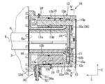
- FIG. 3 is a sectional view taken along the line III-III in FIG. It is a longitudinal cross-sectional view of a slide lock apparatus.
- FIG. 5 is a cross-sectional view taken along line VV in FIG. 4.
- FIG. 6 is a view corresponding to FIG. 5 for explaining an insertable position.
- FIG. 6 is a diagram corresponding to FIG. 4 according to the second embodiment. It is a principal part enlarged view of FIG.
- a slide lock device for a press machine is a device that locks the slide by locking a shaft member that rotates in conjunction with the lifting and lowering operation of the slide of the press machine so as not to rotate.
- the direction of the arrow L is described as the left side and the direction of the arrow U is described as the upper side.
- the press machine 1 is a general crank press, and the press machine 1 includes a main body frame 3, a bolster 4, and a slide supported by the main body frame 3 so as to be movable up and down. 2, the slide 2 is driven up and down via a pair of connecting rods 5, and a crankshaft 6 (shaft member) whose axis X extends in the left-right direction, and a main gear 7 fixed to the left end of the crankshaft 6 A flywheel 8 connected to the main gear 7 via a gear (not shown), a clutch mechanism 9, and an electric motor (not shown) for rotating and driving a pulley 8 a connected to the flywheel 8 by a belt. Yes.
- the slide lock device 10 is attached to the extension shaft portion 6 a on the right end side of the crankshaft 6 and the main body frame 3.
- the annular piston member 13 is made of, for example, an aluminum alloy, and most other members are made of steel.
- the seal member is made of synthetic resin.
- the slide lock device 10 includes a flange member 11 that rotates synchronously with the crankshaft 6, a main body member 12, an annular piston member 13 that can move forward and backward in the direction of the axis X, and a plurality of metal (for example, four) members having a predetermined strength. ) Pin member 14, auxiliary body member 15, annular cylinder hole 17 that accommodates annular piston member 13, lock mechanism 30 that can regulate the forward movement of annular piston member 13, and the like. The device is driven from the insertion position to the retracted position.
- the position of the pin member 14 shown in FIG. 3 is the retracted position
- the position of the pin member 14 shown in FIG. 4 is the insertion position
- the tip (right end) of the pin member 14 is the flange portion 11b.
- the position in contact with the left end surface is the insertable position.
- the extension shaft portion 6a protrudes to the right by a predetermined length from the outer surface on the right end side of the main body frame 3.
- the flange member 11 is an annular member that is externally fitted to the extension shaft portion 6a and is fixed so as not to be relatively rotatable.
- the flange member 11 is tightly fitted to the extension shaft portion 6a and is fixed so as not to rotate relative to the extension shaft portion 6a.
- the flange member 11 is formed integrally with the right end portion of the tube portion 11a and the shaft center X of the crankshaft 6. It has the annular flange part 11b extended to an outer peripheral side along the orthogonal plane.
- the thickness of the flange portion 11b in the left-right direction is set to a predetermined thickness.
- This flange member 11 is firmly fitted between a pair of key grooves 21 formed in the cylinder portion 11a extending in the left-right direction and a pair of key grooves 6b formed in the extension shaft portion 6a extending in the left-right direction.
- the pair of key members 22 are rotationally restricted so as not to rotate relative to the extension shaft portion 6a.
- the flange member 11 is fixed via a bolt 24b to a circular holding plate 24 fixed to the tip of the extension shaft portion 6a by a bolt 24a so as not to move relatively in the left-right direction.
- six arc-shaped introduction holes 11 p are formed in the flange portion 11 b in the circumferential direction at positions spaced apart from the axis X of the crankshaft 6 by a predetermined distance.
- the introduction hole 11p can be inserted and engaged with the right end portion of the pin member 14, the circumferential width of the introduction hole 11p is about three times the diameter of the pin member 14, and the angle ⁇ is, for example, 30 degrees.
- the pin member 14 is in contact with the position of the pin member 14 before the pin member 14 is inserted into the introduction hole 11 p by rotating the crankshaft 6 by a small angle and the left end surface of the flange portion 22.
- the position 14 is an insertable position.
- the main body member 12 is an annular member that is externally fitted to the cylindrical portion 11a so as to be concentric with the crankshaft 6 with a small space therebetween so as to be relatively rotatable.
- the main body member 12 is fixed to the right outer surface of the main body frame 3 of the press machine 1 by fixing a fixing flange 12 d formed at the left end portion of the main body member 12 to the main body frame 3 with a plurality of bolts 12 e.
- the main body member 12 extends from the fixing flange 12d to the outer peripheral side of the flange portion 11b, and is externally fitted to the cylindrical portion 11a so as to be relatively rotatable with an outer cylindrical portion 12a that forms a minute gap with the outer peripheral surface of the flange portion 11b. And an inner cylindrical portion 12b extending in the left-right direction, and a first annular opposing annular wall portion 12c that connects the right end portion of the inner cylindrical portion 12b and the right end portion of the outer cylindrical portion 12a.
- a first opposing wall portion 12c approaching and facing from the member 13 side, and a closing plate 16 for sealing the left end portion of the annular cylinder hole 17 formed between the outer cylinder portion 12a and the inner cylinder portion 12b are provided.
- the closing plate 16 is fixed to the main body member 12 by a plurality of bolts 16a. Further, an auxiliary main body member 15 that covers the main body member 12, the flange portion 11b, and the right end side of the presser plate 24 is provided, and the auxiliary main body member 15 is fixed to the main body member 12 by a plurality of bolts (not shown).
- the first opposing wall portion 12c is formed so as to be close to and opposed to the flange portion 22 from the left side, and is opposed to the flange portion 22 with a gap of 2 to 3 mm.
- four first support holes 12p parallel to the shaft center X at the same distance as the distance from the shaft center X of the crankshaft 6 to the introduction hole 11p are divided into four equal circumferences. Formed in position.
- the first support hole 12p is formed as a hole having a circular cross section into which the pin member 14 is slidably inserted in the left-right direction.
- the main body member 12 is formed with an annular cylinder hole 17 formed concentrically with the axis X of the crankshaft 6 and extending in the left-right direction.
- the annular cylinder hole 17 is partitioned by the outer cylinder portion 12 a, the inner cylinder portion 12 b, the first opposing wall portion 12 c, and the closing plate 16.
- An annular piston member 13 shorter than the annular cylinder hole 17 is mounted in the annular cylinder hole 17 so as to be slidable in a direction parallel to the axis X.
- a large diameter portion 13c is formed in the left end side portion of the annular piston member 13, and a large diameter hole portion 17c longer than the large diameter portion 13c is formed in the annular cylinder hole 17.
- annular first working chamber 17 a (first fluid pressure working chamber) is formed on the left side of the annular piston member 13, and annular on the right side of the large diameter portion 13 c in the large diameter hole portion 17 c.
- the second working chamber 17b (second fluid pressure working chamber) is formed.
- the first and second working chambers 17a and 17b are respectively connected to first and second air ports 18 and 19 provided in the outer cylinder portion 12a, and are configured to be able to supply and discharge pressurized air, respectively.
- the first air port 18 is formed in a penetrating manner in the vicinity of the left end of the outer cylinder portion 12a, and communicates with the first working chamber 17a through a gap on the outer peripheral side of the large diameter portion 13c.
- the second air port 19 is formed in a penetrating manner in the middle of the outer cylinder portion 12a, and communicates with the right end portion of the second working chamber 17b.
- the first and second air ports 18 and 19 are connected to a pressurized air supply source (not shown) by an air hose or an air pipe, respectively.
- the auxiliary main body member 15 is opposed to the flange portion 11b, the presser plate 24, and the outer cylinder portion 12a from the right side, and is fixed to the main body member 12 with a plurality of bolts (not shown).
- the auxiliary body member 15 has a second opposing wall portion 15a that faces the flange portion 11b from the right side.
- the second opposing wall portion 15a is formed in parallel with the flange portion 11b, and is opposed to the flange portion 11b with a gap of 2 to 3 mm.
- the second opposing wall portion 15a is parallel to the shaft center X so as to face the four first support holes 12p, respectively, at a position separated by the same distance as the distance from the shaft center X of the crankshaft 6 to the introduction hole 11p.
- Four second support holes 15p are formed at the circumferentially equally divided position.
- the second support hole 15p is formed as a hole having a circular cross section into which the pin member 14 can be slidably inserted.
- the annular piston member 13 is made of a metal (for example, aluminum alloy) that is lighter than the pin member 14 and is mounted in the annular cylinder hole 17 so as to be movable in the left-right direction (a direction parallel to the axis X). As shown in FIGS. 3 and 4, the annular piston member 13 includes a left end surface 13 a and a right end surface 13 b that are orthogonal to the axis X of the crankshaft 6, and is formed shorter than the length of the annular cylinder hole 17. Yes.
- a metal for example, aluminum alloy
- the annular piston member 13 is opposed to the four first support holes 12p and the four second support holes 15p at positions separated by the same distance as the distance from the axis X of the crankshaft 6 to the introduction hole 11p.
- Four holding holes 13p that are parallel to the axis X are formed at equally spaced positions on the circumference.
- the holding hole 13p is formed as a hole having a circular cross section in which the pin member 14 is slidably mounted, and the four pin members 14 are mounted so as to be movable in the left-right direction (in the direction parallel to the axis X).
- Each pin member 14 is formed with a locking portion 14a (a hook-like portion) formed on the left end portion thereof with a diameter larger than the diameter of the holding hole 13p and facing the first working chamber 17a.
- each pin member 14 has its distal end portion (right end portion) inserted into the first support hole 12p, the introduction hole 11p, and the second support hole 15p, or the distal end abuts against the flange portion 11b. It becomes an insertable position.
- each pin member 14 When the pressurized air is supplied to the second working chamber 17b and the pressurized air is discharged from the first working chamber 17a, the annular piston member 13 moves to the left and moves to the retracted position to the maximum, and each pin member 14 is a retracted position. At this retracted position, the locking portion 14a of each pin member 14 comes into contact with the closing plate 16, and the tip (right end) is in the retracted position retracted to the annular piston member 13 side from the introduction hole 11p.
- the locking portion 14a When the annular piston member 13 moves to the forward movement position, the locking portion 14a receives the pressure of the pressurized air in the first working chamber 17a, so the locking portion 14a of the pin member 14 is the left end surface 13a of the annular piston member 13. In a state where it is in contact with the annular piston member 13, it moves to the right integrally with the annular piston member 13, and becomes an insertion position or an insertable position.
- the lock mechanism 30 locks the annular piston member 13 to the retracted position where it is retracted to the maximum, and locks the four pin members 14 to the retracted position.
- a locking recess 13r is formed in the lower outer peripheral portion of the annular piston member 13 in the vicinity of the left end.
- the locking mechanism 30 includes a double-acting small air cylinder 30a having a piston member 31 that can be engaged with the locking recess 13r when the annular piston member 13 is in the retracted position.
- the air cylinder 30a includes a piston member 31, a case member 32, a forward air chamber 32a, and a backward air chamber 32b.
- the piston member 31 includes a piston portion 31a and a piston rod 31b.
- the forward air chamber 32a and the backward air chamber 32b are connected to a pressurized air supply source by an air hose or an air pipe (not shown).
- pressurized air is supplied to the forward movement air chamber 32a when the annular piston member 13 is in the retracted position, the piston member 31 moves to the annular piston member 13 side, and the tip of the piston rod 31b is engaged with the recess 13r.
- the locked position shown in FIG. 3 is obtained.
- the piston member 31 When pressurized air is supplied to the return air chamber 32b, the piston member 31 returns to the original position where it does not engage with the recess 13r.
- the annular piston member 13 When the annular piston member 13 is in the forward movement position, a part of the piston rod 31b of the piston member 31 in the original position (returned state) faces the outer peripheral surface of the annular piston member 13, so that the piston member 31 is the annular piston member. 13 is incapable of moving (the lock mechanism 30 is inoperable). This is to prevent the piston rod 31b from being advanced into the first working chamber 17a and making the annular piston member 13 unretractable when the annular piston member 13 is in the forward movement position, thereby achieving failsafe.
- a detection rod 41 extending from the piston member 31 of the air cylinder 30a to the opposite side of the piston rod 31b and projecting a predetermined length from the case member 32 is formed integrally with the piston member 31, and a detector 42 is provided at the tip of the detection rod 41. Is provided, and when the piston member 31 is in the original position, a first proximity switch 43a that is close to the detector 42 and a second proximity switch 43b that is close to the detector 42 when the piston member 31 is in the locked position are provided. ing.
- the first and second detection switches 43 a and 43 b are electrically connected to a control unit (not shown) that controls the slide lock device 10.
- the second opposing wall portion 15a of the auxiliary main body member 15 is equipped with four proximity switches 35a that are close to the outer peripheral surface of the right end portion of the pin member 14 in a state where the four pin members 14 are in the insertion position. These four proximity switches 35a are electrically connected to the control unit. When the four pin members 14 are in the insertion position, the corresponding proximity switch 35a is turned on, so that it is possible to detect that the four pin members 14 are in the insertion position.
- an annular cylinder hole 17 is formed in the main body member 12, and the annular piston member 13 is mounted in the annular cylinder hole 17 so as to be movable in a direction parallel to the axis X, and the first working chamber 17a.
- the annular piston member 13 can be driven to the forward position with the pressurized air, and the annular piston member 13 can be switched to the retracted position with the pressurized air in the second working chamber 17b.
- pin members 14 are attached to the four holding holes 13p formed in the annular piston member 13 so as to be able to advance and retreat, and the four first support holes formed in the first opposing wall portion 12c of the main body member 12.
- the four pin members 14 are inserted into the four introduction holes 11p of the flange portion 11b and the four second support holes 15p of the second opposing wall portion 15a.
- the extension shaft portion 6a and the flange member 11b can be locked so as not to rotate.
- the four pin members 14 are switched to the retracted position and switched to the state retracted from the four introduction holes 11p and the second support hole 15p, and the extension shaft portion 6a and the flange member are switched. 11 can be unlocked.
- the four pin members 14 are collectively moved through the annular piston member 13 by the pressurized air in the first and second working chambers 17a and 17b. Since it is configured to be moved and driven, the configuration for moving and driving the four pin members 14 over the insertion position and the retracted position can be remarkably simplified, the number of parts can be reduced, and the manufacturing cost can be reduced.
- the tip side portions of the pin members 14 are inserted into the first support holes 12p, the introduction holes 11p, and the second support holes 15p, and both ends of the flange portions 11b on both sides. Since it is in a supported state, it is advantageous in terms of strength and durability of the pin member 14.
- the pressurized air in the first working chamber 17a The four pin members 14 can be driven in the insertion direction in synchronization with the forward movement of the annular piston member 13, and the four pin members 14 can be driven in the retracting direction in synchronization with the backward movement of the annular piston member 13. it can.
- Each pin member 14 can also be locked to the annular piston member 13 by the locking portion 14a.
- a lock mechanism 40 that can be locked at a retracted position in which the annular piston member 13 is retracted to the maximum is provided, and the four pin members 14 are retracted to hold the annular piston member 13 in the retracted position during operation of the press machine 1.
- the position can be reliably held, and fail safe can be achieved. Further, since the lock mechanism 40 cannot be operated when the annular piston member 13 is in the forward movement position, fail-safe can be achieved.
- the four pin members 14 are in the retracted position by the one set of retracted position detecting means 40 of this simple configuration. Can be detected.
- the four first insertion position detecting means 35 for detecting that the four pin members 14 are in the insertion position are provided on the second opposing wall portion 15a, it is possible to reliably detect that the slide 2 is in the locked state. Can do.
- slide lock device 10A according to the second embodiment will be described with reference to FIGS.
- a set of second insertion position detection means 50 is provided in place of the plurality of first insertion position detection means 35. Since other configurations are not changed, only different configurations will be described.
- a circular plate 51 (corresponding to a moving member) is disposed in the vicinity of the right side of the second opposing wall portion 15 a of the auxiliary main body member 15 and the four pin members 14, and the guide is fixed to the central portion of the circular plate 51.
- the shaft 52 is inserted into a guide hole 53 formed in the second opposing wall portion 15a so as to be movable in the left-right direction.
- a detected portion 53 a is formed at the tip of the guide shaft 53.
- a circular cover plate 54 is fixed to the rear end of the auxiliary main body member 15 with a plurality of screws on the outer side (right side) of the circular plate 51.
- a spring receiving plate 54b is integrally formed with the boss portion 54a at the center of the cover plate 54, and a proximity switch 55 is mounted on the spring receiving plate 54b in the boss portion 54a.
- a compression spring 56 is mounted on the outer peripheral side of the detected portion 52a and the proximity switch 55, and the circular plate 51 is urged to the left by the compression spring 56 and is held in contact with the tips of the four pin members 14. ing.
- the circular plate 51 comes into contact with the second opposing wall portion 15a, and the gap between the detected portion 52a and the proximity switch 55 is enlarged. Is turned off.
- the circular plate 51 is pushed rightward by the pin member 14 and the gap between the detected portion 52a and the proximity switch 55 is reduced, so that the proximity switch 55 is turned on.
- the proximity switch 55 is electrically connected to the control unit.
- the second insertion position detection means 50 can detect that the four pin members 14 are in the insertion position with one set of detection means, the number of parts is small, the configuration is simple, and the manufacturing cost can be reduced.
- the number of holding holes 13p, first and second support holes 12p, 15p, and pin members 14 is not limited to four, and may be three or less, or five or more.
- the number of introduction holes 11p is not limited to six, and may be five or less, or seven or more. Depending on the number of the introduction holes 11p, the size of the introduction hole 11p in the circumferential direction can be set as appropriate.
- a fixing flange portion is formed on the auxiliary main body member 15, the auxiliary main body member 15 is brought into contact with the main body frame 3a, and the fixing flange portion is fixed to the main body frame 3a with a plurality of bolts.
- the auxiliary body member 15 may be extended through, the presser plate 24 may be omitted, and the closing plate 16 side may be a free end side.
- the main body member 12 is fixed to the main body frame 3 a via the auxiliary main body member 15.
- the present invention provides a slide lock device that can securely lock a slide of a press machine as required.
Landscapes
- Engineering & Computer Science (AREA)
- Mechanical Engineering (AREA)
- Control Of Presses (AREA)
- Automatic Assembly (AREA)
- Press Drives And Press Lines (AREA)
Abstract
Description
(1)前記第1対向壁部と反対側において前記フランジ部に接近対向する第2対向壁部を有する補助本体部材であって前記本体部材に固定された補助本体部材を設け、前記第2対向壁部には複数の第1支持孔に対向する複数の第2支持孔であって前記挿入位置にある複数のピン部材の先端部が挿入される複数の第2支持孔が形成される。
(3)前記環状ピストン部材を最大限後退させた後退位置にロック可能なロック機構を設ける。
(5)前記(1)において、前記補助本体部材に前記複数のピン部材が挿入位置にあることを夫々検出する複数の第1挿入位置検知手段を設ける。
このスライドロック装置10において、環状ピストン部材13は例えばアルミニウム合金製であり、その他の大部分の部材は鋼製である。但し、シール部材は合成樹脂製である。
スライドロック装置10は、クランク軸6と同期回転するフランジ部材11と、本体部材12と、軸心X方向に進退移動可能な環状ピストン部材13と、所定強度を有する金属製の複数(例えば4つ)のピン部材14と、補助本体部材15と、環状ピストン部材13を収容する環状シリンダ孔17と、環状ピストン部材13の前進移動を規制可能なロック機構30等を備え、複数のピン部材14を挿入位置から退避位置に亙って駆動する装置である。
フランジ部材11は、左右方向へ相対移動しないように、延長軸部6aの先端にボルト24aで固定された円形の押え板24にボルト24bを介して固定されている。
図2~図5に示すように、本体部材12は、クランク軸6に対して同心状になるように筒部11aに微小間隔を空けて相対回転自在に外嵌された環状の部材である。本体部材12の左端部に形成された固定用フランジ12dを複数のボルト12eによって本体フレーム3に固定することにより、本体部材12をプレス機械1の本体フレーム3の右側外側面に固定している。
この第1対向壁部12cには、クランク軸6の軸心Xから導入孔11pまでの距離と同距離離隔した位置において軸心Xと平行な4つの第1支持孔12pが円周4等分位置に形成されている。第1支持孔12pはピン部材14が左右方向へ摺動自在に挿入される断面円形の孔に形成されている。
環状シリンダ孔17内には、この環状シリンダ孔17よりも短い環状ピストン部材13が軸心Xと平行方向へ摺動自在に装着されている。環状ピストン部材13の左端側部分には大径部13cが形成され、環状シリンダ孔17には大径部13cよりも長い大径孔部17cが形成されている。
環状ピストン部材13は、ピン部材14よりも軽量な金属(例えばアルミニウム合金)で構成され、環状シリンダ孔17内に左右方向(軸心Xと平行方向)へ移動可能に装着されている。図3,図4に示すように、この環状ピストン部材13は、クランク軸6の軸心Xと直交状の左端面13a及び右端面13bを備え、環状シリンダ孔17の長さよりも短く形成されている。
各ピン部材14には、その左端部分に保持孔13pの径よりも大径に形成され且つ第1作動室17a内に臨む係止部14a(鍔状部分)が形成されている。
ロック機構30は、プレス機械1の稼働中に、環状ピストン部材13を最大限後退させた後退位置にロックし、4つのピン部材14を退避位置にロックするものである。環状ピストン部材13の左端近傍部分の下側外周部分にはロック用凹部13rが形成されている。ロック機構30は、環状ピストン部材13が後退位置にあるとき、ロック用凹部13rに係合可能なピストン部材31を有する複動型の小型エアシリンダ30aを有する。
このスライドロック装置10によれば、本体部材12に環状シリンダ孔17を形成し、この環状シリンダ孔17に環状ピストン部材13を軸心Xと平行方向へ移動可能に装着し、第1作動室17aの加圧エアで環状ピストン部材13を前進位置に駆動し、第2作動室17bの加圧エアで環状ピストン部材13を後退位置に切換えることができる。
1)保持孔13pと第1,第2支持孔12p,15pとピン部材14の数は4つに限定されるものではなく、3つ以下でもよく5つ以上でもよい。導入孔11pの数は6つに限定されるものではなく、5つ以下でもよく7つ以上でもよい。導入孔11pの数に応じて導入孔11pの周方向のサイズも適宜設定可能である。
3)前記実施例では、ピン部材14の係止部14aが環状ピストン部材13の左端面から左方に突出した例を説明したが、環状ピストン部材13の左端面に凹部を形成して係止部14aの左端面と環状ピストン部材13の左端面とが同一面になるように形成しても良い。
2 スライド
3 本体フレーム
6 クランク軸
6a 延長軸部
10 スライドロック装置
11 フランジ部材
11a 筒部
11b フランジ部
11p 導入孔
12 本体部材
12c 第1対向壁部
12p 第1支持孔
13 環状ピストン部材
13p 保持孔
14 ピン部材
14a 係止部
15 補助本体部材
15a 第2対向壁部
15p 第2支持孔
17 環状シリンダ孔
17a 第1作動室
17b 第2作動室
30 ロック機構
40 後退位置検知手段
35 第1挿入位置検知手段
50 第2挿入位置検知手段
51 円形板(移動部材)
Claims (7)
- プレス機械の本体フレームに支持されたスライドの昇降動作と連動して回転する軸部材を回転不能にロックするプレス機械のスライドロック装置であって、
前記軸部材に外嵌されて相対回転不能に固定された筒部とこの筒部の端部から前記軸部材の軸心と直交する面に沿って外周側へ延びるフランジ部とを有するフランジ部材と、前記筒部に相対回転可能に外嵌されて前記本体フレームに固定された環状の本体部材と、前記本体部材に前記軸心と平行に形成された複数の保持孔と、これら複数の保持孔に進退可能に装着された複数のピン部材と、前記フランジ部に形成された円弧状の複数の導入孔とを備え、前記複数のピン部材を流体圧で前記フランジ部の方へ進出駆動して複数の導入孔に挿入することで、前記フランジ部材を介して前記軸部材を回転不能にロックするプレス機械のスライドロック装置において、
前記本体部材に形成された環状シリンダ孔内に前記軸心と平行方向に所定ストローク移動可能に装着され且つ前記複数の保持孔が形成された環状ピストン部材と、
前記環状シリンダ孔内に形成され環状ピストン部材を前記フランジ部の方へ前進駆動するための環状の第1流体圧作動室と、
前記環状シリンダ孔内に形成され前記環状ピストン部材を前記フランジ部から離隔する方へ後退駆動するための第2流体圧作動室と、
前記フランジ部に環状ピストン側から接近対向するように前記本体部材に形成された第1対向壁部、およびこの第1対向壁部に複数の保持孔に対向するように形成された複数の第1支持孔とを備え、
前記複数のピン部材は、前記複数の保持孔と複数の第1支持孔に軸心方向へ移動自在に夫々装着されると共に前記第1流体圧作動室の流体圧を受圧可能に構成され、
前記第1流体圧作動室の流体圧により前記環状ピストン部材を前進駆動したとき、前記第1流体圧作動室の流体圧により複数のピン部材を前記導入孔に挿入させた挿入位置または挿入可能位置にすると共に、前記第2流体圧作動室の流体圧により前記環状ピストン部材を後退駆動したとき、複数のピン部材を前記導入孔よりも前記環状ピストン部材側へ退避させた退避位置に切換えるように構成したことを特徴とするプレス機械のスライドロック装置。 - 前記第1対向壁部と反対側において前記フランジ部に接近対向する第2対向壁部を有する補助本体部材であって前記本体部材に固定された補助本体部材を設け、
前記第2対向壁部には複数の第1支持孔に対向する複数の第2支持孔であって前記挿入位置にある複数のピン部材の先端部が挿入される複数の第2支持孔が形成されたことを特徴とする請求項1に記載のプレス機械のスライドロック装置。 - 前記ピン部材の本体フレーム側の基端部に、前記保持孔よりも大径の係止部を設けたことを特徴とする請求項1に記載のプレス機械のスライドロック装置。
- 前記環状ピストン部材を最大限後退させた後退位置にロック可能なロック機構を設けたことを特徴とする請求項1に記載のプレス機械のスライドロック装置。
- 前記環状ピストン部材が後退位置にあることを検知する後退位置検知手段を設けたことを特徴とする請求項4に記載のプレス機械のスライドロック装置。
- 前記補助本体部材に前記複数のピン部材が挿入位置にあることを夫々検出する複数の第1挿入位置検知手段を設けたことを特徴とする請求項2に記載のプレス機械のスライドロック装置。
- 前記補助本体部材に、前記第2支持孔を貫通した複数のピン部材と一体的に前記軸心方向に移動可能な移動部材と、前記移動部材の移動を介して前記複数のピン部材が挿入位置にあることを検知可能な第2挿入位置検知手段を設けたことを特徴とする請求項2に記載のプレス機械のスライドロック装置。
Priority Applications (7)
| Application Number | Priority Date | Filing Date | Title |
|---|---|---|---|
| EP14907594.7A EP3228445B1 (en) | 2014-12-02 | 2014-12-02 | Slide lock device for press machine |
| KR1020177015038A KR102235518B1 (ko) | 2014-12-02 | 2014-12-02 | 프레스 기계의 슬라이드 로크 장치 |
| JP2016562119A JP6441381B2 (ja) | 2014-12-02 | 2014-12-02 | プレス機械のスライドロック装置 |
| PCT/JP2014/081830 WO2016088194A1 (ja) | 2014-12-02 | 2014-12-02 | プレス機械のスライドロック装置 |
| ES14907594T ES2759998T3 (es) | 2014-12-02 | 2014-12-02 | Dispositivo de bloqueo de carro para prensa |
| US15/528,788 US10486386B2 (en) | 2014-12-02 | 2014-12-02 | Slide lock device for press machine |
| CN201480083790.2A CN107000356B (zh) | 2014-12-02 | 2014-12-02 | 冲压机的滑块锁定装置 |
Applications Claiming Priority (1)
| Application Number | Priority Date | Filing Date | Title |
|---|---|---|---|
| PCT/JP2014/081830 WO2016088194A1 (ja) | 2014-12-02 | 2014-12-02 | プレス機械のスライドロック装置 |
Publications (1)
| Publication Number | Publication Date |
|---|---|
| WO2016088194A1 true WO2016088194A1 (ja) | 2016-06-09 |
Family
ID=56091173
Family Applications (1)
| Application Number | Title | Priority Date | Filing Date |
|---|---|---|---|
| PCT/JP2014/081830 Ceased WO2016088194A1 (ja) | 2014-12-02 | 2014-12-02 | プレス機械のスライドロック装置 |
Country Status (7)
| Country | Link |
|---|---|
| US (1) | US10486386B2 (ja) |
| EP (1) | EP3228445B1 (ja) |
| JP (1) | JP6441381B2 (ja) |
| KR (1) | KR102235518B1 (ja) |
| CN (1) | CN107000356B (ja) |
| ES (1) | ES2759998T3 (ja) |
| WO (1) | WO2016088194A1 (ja) |
Cited By (1)
| Publication number | Priority date | Publication date | Assignee | Title |
|---|---|---|---|---|
| US9789659B2 (en) * | 2013-02-08 | 2017-10-17 | Pascal Engineering Corporation | Slide lock apparatus for press machine |
Families Citing this family (1)
| Publication number | Priority date | Publication date | Assignee | Title |
|---|---|---|---|---|
| WO2023009123A1 (en) * | 2021-07-29 | 2023-02-02 | Signode Industrial Group Llc | Press-type strapping machine with platen-locking system |
Citations (3)
| Publication number | Priority date | Publication date | Assignee | Title |
|---|---|---|---|---|
| JPS51123972A (en) * | 1975-04-23 | 1976-10-29 | Aida Eng Ltd | Method for preventing double-dropping in a press machine |
| US5845751A (en) * | 1996-07-01 | 1998-12-08 | Chant; William | Safety locking device |
| JP2005059065A (ja) * | 2003-08-13 | 2005-03-10 | Ishikawajima Harima Heavy Ind Co Ltd | ロック装置及びプレス装置 |
Family Cites Families (12)
| Publication number | Priority date | Publication date | Assignee | Title |
|---|---|---|---|---|
| US2185551A (en) * | 1938-10-27 | 1940-01-02 | Glasner | Safety locking mechanism for presses and the like |
| US5269059A (en) * | 1992-04-13 | 1993-12-14 | Schuler Incorporated | Method of installing a slide locking mechanism in a press |
| DE4330870C1 (de) * | 1993-09-11 | 1994-09-08 | Keiper Recaro Gmbh Co | Verriegelungssystem für verstellbare Fahrzeugsitze |
| JP3922609B2 (ja) * | 1998-03-05 | 2007-05-30 | パスカルエンジニアリング株式会社 | プレス機械のスライドロック装置 |
| CN1162271C (zh) * | 1999-02-22 | 2004-08-18 | 帕斯卡工程株式会社 | 机械压力机的离合器制动器装置 |
| JP4365469B2 (ja) * | 1999-02-24 | 2009-11-18 | パスカルエンジニアリング株式会社 | 油圧式ロック装置 |
| JP2001129698A (ja) * | 1999-10-29 | 2001-05-15 | Aida Eng Ltd | スライドロック装置 |
| JP2004174577A (ja) * | 2002-11-28 | 2004-06-24 | Sr Engineering Co Ltd | プレス機械のスライドロック装置 |
| JP4806276B2 (ja) | 2006-03-14 | 2011-11-02 | 株式会社小松製作所 | スライドのロック装置およびこれを備えたプレス機械 |
| EP2878438B1 (en) * | 2012-07-24 | 2017-07-05 | Pascal Engineering Corporation | Slide lock device for machine presses |
| KR101947730B1 (ko) * | 2013-02-08 | 2019-02-13 | 파스칼 엔지니어링 가부시키가이샤 | 프레스 기계의 슬라이드 로크 장치 |
| US9896574B2 (en) | 2013-04-10 | 2018-02-20 | Dow Global Technologies Llc | Films with improved dart impact resistance |
-
2014
- 2014-12-02 US US15/528,788 patent/US10486386B2/en active Active
- 2014-12-02 CN CN201480083790.2A patent/CN107000356B/zh not_active Expired - Fee Related
- 2014-12-02 EP EP14907594.7A patent/EP3228445B1/en not_active Not-in-force
- 2014-12-02 ES ES14907594T patent/ES2759998T3/es active Active
- 2014-12-02 WO PCT/JP2014/081830 patent/WO2016088194A1/ja not_active Ceased
- 2014-12-02 JP JP2016562119A patent/JP6441381B2/ja not_active Expired - Fee Related
- 2014-12-02 KR KR1020177015038A patent/KR102235518B1/ko not_active Expired - Fee Related
Patent Citations (3)
| Publication number | Priority date | Publication date | Assignee | Title |
|---|---|---|---|---|
| JPS51123972A (en) * | 1975-04-23 | 1976-10-29 | Aida Eng Ltd | Method for preventing double-dropping in a press machine |
| US5845751A (en) * | 1996-07-01 | 1998-12-08 | Chant; William | Safety locking device |
| JP2005059065A (ja) * | 2003-08-13 | 2005-03-10 | Ishikawajima Harima Heavy Ind Co Ltd | ロック装置及びプレス装置 |
Cited By (1)
| Publication number | Priority date | Publication date | Assignee | Title |
|---|---|---|---|---|
| US9789659B2 (en) * | 2013-02-08 | 2017-10-17 | Pascal Engineering Corporation | Slide lock apparatus for press machine |
Also Published As
| Publication number | Publication date |
|---|---|
| EP3228445B1 (en) | 2019-11-06 |
| KR102235518B1 (ko) | 2021-04-01 |
| US20170313014A1 (en) | 2017-11-02 |
| EP3228445A4 (en) | 2018-08-22 |
| KR20170091105A (ko) | 2017-08-08 |
| CN107000356B (zh) | 2018-11-02 |
| EP3228445A1 (en) | 2017-10-11 |
| JP6441381B2 (ja) | 2018-12-19 |
| US10486386B2 (en) | 2019-11-26 |
| ES2759998T3 (es) | 2020-05-12 |
| JPWO2016088194A1 (ja) | 2017-11-16 |
| CN107000356A (zh) | 2017-08-01 |
Similar Documents
| Publication | Publication Date | Title |
|---|---|---|
| JP5588933B2 (ja) | 油圧作動システム | |
| ITMO20100250A1 (it) | "dispositivo per il bloccaggio di cerchi di ruote per veicoli su macchine da autofficina, particolarmente macchine smontagomme o simili" | |
| JP2012166276A (ja) | クランプ装置のロッド位置検出装置 | |
| CN102943786A (zh) | 液压缸 | |
| JP6441381B2 (ja) | プレス機械のスライドロック装置 | |
| KR100644512B1 (ko) | 형체장치 | |
| JP5118708B2 (ja) | 流体圧シリンダ | |
| JP6076380B2 (ja) | プレス機械のスライドロック装置 | |
| KR101947744B1 (ko) | 프레스 기계의 슬라이드 잠금 장치 | |
| CN206706873U (zh) | 液压锤组件 | |
| JP2002195211A (ja) | 流体装置及びショットピン装置 | |
| EP2829742B1 (en) | Hydraulic cylinder | |
| US9938769B2 (en) | Ram boring device | |
| US20170107684A1 (en) | A coupler for a wheel loader | |
| US10641299B2 (en) | Monitoring device for tool turret | |
| JP5439159B2 (ja) | 工作機械の主軸装置 | |
| CN209174811U (zh) | 旋转锁模机构、模座及锻造设备 | |
| JP2008110416A (ja) | 流体圧駆動割出装置 | |
| JP3197029U (ja) | 流体圧シリンダ | |
| JP2015212003A (ja) | 締付ソケット及びソケット切り替え方法 | |
| US20130344192A1 (en) | Mold clamping device |
Legal Events
| Date | Code | Title | Description |
|---|---|---|---|
| 121 | Ep: the epo has been informed by wipo that ep was designated in this application |
Ref document number: 14907594 Country of ref document: EP Kind code of ref document: A1 |
|
| WWE | Wipo information: entry into national phase |
Ref document number: 15528788 Country of ref document: US |
|
| ENP | Entry into the national phase |
Ref document number: 20177015038 Country of ref document: KR Kind code of ref document: A |
|
| NENP | Non-entry into the national phase |
Ref country code: DE |
|
| REEP | Request for entry into the european phase |
Ref document number: 2014907594 Country of ref document: EP |
|
| ENP | Entry into the national phase |
Ref document number: 2016562119 Country of ref document: JP Kind code of ref document: A |