WO2016088872A1 - トーショナルダンパとオイルシールとを用いた密封構造 - Google Patents
トーショナルダンパとオイルシールとを用いた密封構造 Download PDFInfo
- Publication number
- WO2016088872A1 WO2016088872A1 PCT/JP2015/084124 JP2015084124W WO2016088872A1 WO 2016088872 A1 WO2016088872 A1 WO 2016088872A1 JP 2015084124 W JP2015084124 W JP 2015084124W WO 2016088872 A1 WO2016088872 A1 WO 2016088872A1
- Authority
- WO
- WIPO (PCT)
- Prior art keywords
- hub
- oil seal
- outer peripheral
- peripheral surface
- torsional damper
- Prior art date
- Legal status (The legal status is an assumption and is not a legal conclusion. Google has not performed a legal analysis and makes no representation as to the accuracy of the status listed.)
- Ceased
Links
Images


Classifications
-
- F—MECHANICAL ENGINEERING; LIGHTING; HEATING; WEAPONS; BLASTING
- F16—ENGINEERING ELEMENTS AND UNITS; GENERAL MEASURES FOR PRODUCING AND MAINTAINING EFFECTIVE FUNCTIONING OF MACHINES OR INSTALLATIONS; THERMAL INSULATION IN GENERAL
- F16J—PISTONS; CYLINDERS; SEALINGS
- F16J15/00—Sealings
- F16J15/16—Sealings between relatively-moving surfaces
- F16J15/32—Sealings between relatively-moving surfaces with elastic sealings, e.g. O-rings
- F16J15/3204—Sealings between relatively-moving surfaces with elastic sealings, e.g. O-rings with at least one lip
- F16J15/3208—Sealings between relatively-moving surfaces with elastic sealings, e.g. O-rings with at least one lip provided with tension elements, e.g. elastic rings
-
- F—MECHANICAL ENGINEERING; LIGHTING; HEATING; WEAPONS; BLASTING
- F16—ENGINEERING ELEMENTS AND UNITS; GENERAL MEASURES FOR PRODUCING AND MAINTAINING EFFECTIVE FUNCTIONING OF MACHINES OR INSTALLATIONS; THERMAL INSULATION IN GENERAL
- F16C—SHAFTS; FLEXIBLE SHAFTS; ELEMENTS OR CRANKSHAFT MECHANISMS; ROTARY BODIES OTHER THAN GEARING ELEMENTS; BEARINGS
- F16C33/00—Parts of bearings; Special methods for making bearings or parts thereof
- F16C33/72—Sealings
- F16C33/76—Sealings of ball or roller bearings
- F16C33/80—Labyrinth sealings
- F16C33/805—Labyrinth sealings in addition to other sealings, e.g. dirt guards to protect sealings with sealing lips
-
- F—MECHANICAL ENGINEERING; LIGHTING; HEATING; WEAPONS; BLASTING
- F16—ENGINEERING ELEMENTS AND UNITS; GENERAL MEASURES FOR PRODUCING AND MAINTAINING EFFECTIVE FUNCTIONING OF MACHINES OR INSTALLATIONS; THERMAL INSULATION IN GENERAL
- F16F—SPRINGS; SHOCK-ABSORBERS; MEANS FOR DAMPING VIBRATION
- F16F15/00—Suppression of vibrations in systems; Means or arrangements for avoiding or reducing out-of-balance forces, e.g. due to motion
- F16F15/10—Suppression of vibrations in rotating systems by making use of members moving with the system
- F16F15/12—Suppression of vibrations in rotating systems by making use of members moving with the system using elastic members or friction-damping members, e.g. between a rotating shaft and a gyratory mass mounted thereon
- F16F15/121—Suppression of vibrations in rotating systems by making use of members moving with the system using elastic members or friction-damping members, e.g. between a rotating shaft and a gyratory mass mounted thereon using springs as elastic members, e.g. metallic springs
- F16F15/124—Elastomeric springs
- F16F15/1245—Elastic elements arranged between substantially-radial walls of two parts rotatable with respect to each other, e.g. between engaging teeth
-
- F—MECHANICAL ENGINEERING; LIGHTING; HEATING; WEAPONS; BLASTING
- F16—ENGINEERING ELEMENTS AND UNITS; GENERAL MEASURES FOR PRODUCING AND MAINTAINING EFFECTIVE FUNCTIONING OF MACHINES OR INSTALLATIONS; THERMAL INSULATION IN GENERAL
- F16F—SPRINGS; SHOCK-ABSORBERS; MEANS FOR DAMPING VIBRATION
- F16F15/00—Suppression of vibrations in systems; Means or arrangements for avoiding or reducing out-of-balance forces, e.g. due to motion
- F16F15/10—Suppression of vibrations in rotating systems by making use of members moving with the system
- F16F15/12—Suppression of vibrations in rotating systems by making use of members moving with the system using elastic members or friction-damping members, e.g. between a rotating shaft and a gyratory mass mounted thereon
- F16F15/121—Suppression of vibrations in rotating systems by making use of members moving with the system using elastic members or friction-damping members, e.g. between a rotating shaft and a gyratory mass mounted thereon using springs as elastic members, e.g. metallic springs
- F16F15/124—Elastomeric springs
- F16F15/126—Elastomeric springs consisting of at least one annular element surrounding the axis of rotation
-
- F—MECHANICAL ENGINEERING; LIGHTING; HEATING; WEAPONS; BLASTING
- F16—ENGINEERING ELEMENTS AND UNITS; GENERAL MEASURES FOR PRODUCING AND MAINTAINING EFFECTIVE FUNCTIONING OF MACHINES OR INSTALLATIONS; THERMAL INSULATION IN GENERAL
- F16H—GEARING
- F16H55/00—Elements with teeth or friction surfaces for conveying motion; Worms, pulleys or sheaves for gearing mechanisms
- F16H55/32—Friction members
- F16H55/36—Pulleys
-
- F—MECHANICAL ENGINEERING; LIGHTING; HEATING; WEAPONS; BLASTING
- F16—ENGINEERING ELEMENTS AND UNITS; GENERAL MEASURES FOR PRODUCING AND MAINTAINING EFFECTIVE FUNCTIONING OF MACHINES OR INSTALLATIONS; THERMAL INSULATION IN GENERAL
- F16J—PISTONS; CYLINDERS; SEALINGS
- F16J15/00—Sealings
- F16J15/02—Sealings between relatively-stationary surfaces
- F16J15/06—Sealings between relatively-stationary surfaces with solid packing compressed between sealing surfaces
- F16J15/10—Sealings between relatively-stationary surfaces with solid packing compressed between sealing surfaces with non-metallic packing
-
- F—MECHANICAL ENGINEERING; LIGHTING; HEATING; WEAPONS; BLASTING
- F16—ENGINEERING ELEMENTS AND UNITS; GENERAL MEASURES FOR PRODUCING AND MAINTAINING EFFECTIVE FUNCTIONING OF MACHINES OR INSTALLATIONS; THERMAL INSULATION IN GENERAL
- F16J—PISTONS; CYLINDERS; SEALINGS
- F16J15/00—Sealings
- F16J15/16—Sealings between relatively-moving surfaces
- F16J15/32—Sealings between relatively-moving surfaces with elastic sealings, e.g. O-rings
- F16J15/3204—Sealings between relatively-moving surfaces with elastic sealings, e.g. O-rings with at least one lip
-
- F—MECHANICAL ENGINEERING; LIGHTING; HEATING; WEAPONS; BLASTING
- F16—ENGINEERING ELEMENTS AND UNITS; GENERAL MEASURES FOR PRODUCING AND MAINTAINING EFFECTIVE FUNCTIONING OF MACHINES OR INSTALLATIONS; THERMAL INSULATION IN GENERAL
- F16J—PISTONS; CYLINDERS; SEALINGS
- F16J15/00—Sealings
- F16J15/44—Free-space packings
- F16J15/447—Labyrinth packings
-
- F—MECHANICAL ENGINEERING; LIGHTING; HEATING; WEAPONS; BLASTING
- F16—ENGINEERING ELEMENTS AND UNITS; GENERAL MEASURES FOR PRODUCING AND MAINTAINING EFFECTIVE FUNCTIONING OF MACHINES OR INSTALLATIONS; THERMAL INSULATION IN GENERAL
- F16F—SPRINGS; SHOCK-ABSORBERS; MEANS FOR DAMPING VIBRATION
- F16F2230/00—Purpose; Design features
- F16F2230/0052—Physically guiding or influencing
-
- F—MECHANICAL ENGINEERING; LIGHTING; HEATING; WEAPONS; BLASTING
- F16—ENGINEERING ELEMENTS AND UNITS; GENERAL MEASURES FOR PRODUCING AND MAINTAINING EFFECTIVE FUNCTIONING OF MACHINES OR INSTALLATIONS; THERMAL INSULATION IN GENERAL
- F16F—SPRINGS; SHOCK-ABSORBERS; MEANS FOR DAMPING VIBRATION
- F16F2230/00—Purpose; Design features
- F16F2230/30—Sealing arrangements
-
- F—MECHANICAL ENGINEERING; LIGHTING; HEATING; WEAPONS; BLASTING
- F16—ENGINEERING ELEMENTS AND UNITS; GENERAL MEASURES FOR PRODUCING AND MAINTAINING EFFECTIVE FUNCTIONING OF MACHINES OR INSTALLATIONS; THERMAL INSULATION IN GENERAL
- F16H—GEARING
- F16H55/00—Elements with teeth or friction surfaces for conveying motion; Worms, pulleys or sheaves for gearing mechanisms
- F16H55/32—Friction members
- F16H55/36—Pulleys
- F16H2055/366—Pulleys with means providing resilience or vibration damping
Definitions
- the present invention relates to a sealing structure using a torsional damper and an oil seal, and in particular, a torsional damper for absorbing torsional vibration generated in a rotating shaft of an engine such as a vehicle, and an oil for the torsional damper
- the present invention relates to a sealing structure formed by a seal.
- a torsional damper is attached to one end of a crankshaft in order to reduce torsional vibration caused by crankshaft rotation fluctuations.
- the torsional damper is used as a damper pulley, and transmits a part of the engine power to an auxiliary machine such as a water pump or an air conditioner compressor via a power transmission belt.
- an auxiliary machine such as a water pump or an air conditioner compressor via a power transmission belt.
- a space between the torsional damper and a through hole of the front cover, for example, through which the crankshaft is inserted is sealed with an oil seal.
- FIG. 22 is a partial cross-sectional view taken along the axis for schematically showing the configuration of a conventional damper pulley and oil seal used in a vehicle engine.
- the conventional damper pulley 100 includes a hub 101, a pulley 102, and a damper elastic body 103 disposed between the hub 101 and the pulley 102.
- the hub 101 includes an inner boss 101a, an outer rim 101b, and a disc 101c that connects the boss 101a and the rim 101b.
- the damper pulley 100 is fixed by a bolt 121 with the boss 101 a of the hub 101 fitted into one end of the crankshaft 120.
- the boss 101a of the hub 101 of the damper pulley 100 attached to the crankshaft 120 is inserted into the through hole 123 of the front cover 122 from the outside of the engine, and the oil seal 110 is press-fitted between the boss 101a and the through hole 123.
- the seal lip 111 is slidably contacted with the boss 101a in a liquid-tight manner to seal between the damper pulley 100 and the front cover 122.
- JP 09-324861 A Japanese Utility Model Publication No. 05-25049 Japanese Patent No. 5556355
- the conventional damper pulley 100 having the window portion 101d can reduce the weight and cost of the damper pulley 100 in the engine.
- foreign matter such as muddy water, sand, and dust is present on the engine side through the window portion 101d. It becomes easy to invade. For this reason, the torsional damper having the window portion has been required to further improve the function of suppressing entry of foreign matter into the seal portion.
- the seal lip 111 of the oil seal 110 is exposed to the foreign matter entering from the outer periphery of the damper pulley 100 and the foreign matter entering from the window portion 101d. There was a request to further prevent this. In addition, due to diversification of vehicle usage environments in recent years, there has been a demand for further prevention of exposure of the seal lip 111 of the oil seal 110 to foreign matters entering from the outside.
- the present invention has been made in view of the above-described problems, and an object of the present invention is torsional damper and oil seal capable of suppressing exposure of seal lip of oil seal to foreign matter entering from torsional damper. It is providing the sealing structure using these.
- a sealing structure using a torsional damper and an oil seal is a sealing structure using a torsional damper and an oil seal
- the torsional damper includes a hub and An annular mass body centering on an axis covering the hub on the outer periphery, and a damper elastic body disposed between the hub and the mass body to elastically connect the hub and the mass body
- the torsional damper is attached to one end of a rotating shaft with the hub inserted through a through-hole of the mounted portion, and the oil seal includes an annular seal lip centered on the axis and the axis.
- An annular side lip having a center, and is attached to the through hole of the attached portion to seal between the hub and the through hole of the attached portion, and the hub is centered on the axis
- An annular hub pocket centered on the axis, and the hub pocket has an annular outer peripheral surface opposed to the boss portion on the outer peripheral side, and an annular centered on the axis recessed in the disk portion direction.
- a concave portion is formed, and the outer peripheral surface of the hub pocket is enlarged in diameter toward the disk portion direction on the axis, and in the oil seal, the seal lip is directly or indirectly on the boss portion.
- the side lip is slidably abutted and extends toward the hub pocket to form an annular gap with the outer peripheral surface of the hub pocket.
- the side lip has the annular gap between the outer peripheral surface of the hub pocket and the oil seal side end. Forming.
- the side lip faces the outer peripheral surface of the hub pocket, and the side lip and the outer peripheral surface of the hub pocket are The annular gap is formed between the two.
- a diameter expansion angle that is an angle with respect to the axis of the diameter increasing outer peripheral surface of the hub pocket is 4 ° or more and 18 ° or less.
- the diameter of the hub pocket that is the diameter of the outer peripheral surface to be expanded is an angle with respect to the axis, and the angle of the side lip with respect to the axis
- the gap angle difference which is the difference from the tilt angle, is 1.0 ° or more and 11.0 ° or less.
- the hub has an annular accessory ring member that is detachably attached to the boss portion of the hub, and the accessory The outer peripheral surface of the hub pocket is formed on the ring member.
- the disk part of the hub of the torsional damper includes a window part that penetrates the disk part.
- a sealing structure using a torsional damper and an oil seal is a sealing structure using a torsional damper and an oil seal, and has a hollow annular shape centering on an axis.
- the torsional damper includes a hub, an annular mass body centering on an axis that covers the hub at an outer periphery, and the hub and the mass body.
- a damper elastic body that elastically connects the mass body, and the torsional damper is attached to one end of a rotating shaft with the hub inserted through a through-hole of the attached portion, and the ring member is
- the oil seal is formed so as to be fitted in the through hole of the attached portion, and has an annular protrusion centered on the axis, and the oil seal is an annular seal lip centered on the axis.
- the hub is attached to the through hole of the attached portion via the ring member to seal between the hub and the through hole of the attached portion, and the hub is an annular boss centered on the axis
- An annular rim centered on the axis positioned on the outer periphery of the boss, a disk-shaped disk centered on the axis connecting the boss and the rim, and the axis
- An annular hub pocket having a center, the hub pocket having an annular outer peripheral surface facing the boss portion on the outer peripheral side, and forming an annular recess centering on the axis recessed in the disk portion direction.
- the outer peripheral surface of the hub pocket is enlarged in diameter toward the disc portion in the axis, and the seal lip is slidable directly or indirectly on the boss portion in the oil seal. Abutting and said ring In wood, the protrusions extend toward said hub pockets, and wherein the forming the annular gap between the outer peripheral surface of said hub pockets.
- the disk part of the hub of the torsional damper includes a window part that penetrates the disk part.
- the sealing structure using the torsional damper and the oil seal according to the present invention it is possible to suppress the seal lip of the oil seal from being exposed to foreign matters entering from the torsional damper.
- FIG. 1 It is a fragmentary sectional view in the section which meets an axis for showing a schematic structure of a sealing structure using a torsional damper and an oil seal concerning a 1st embodiment of the present invention. It is a rear view for showing the schematic structure of the torsional damper in the sealing structure shown in FIG. It is the elements on larger scale of the sealing structure using the torsional damper and oil seal shown in FIG. It is a fragmentary sectional view in the section which meets the axis line for showing the schematic structure of the oil seal for evaluation tests in the example of the sealing structure test using the torsional damper and oil seal concerning the present invention.
- Drawing 5 (a) is a fragmentary sectional perspective view
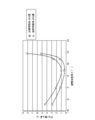
- Drawing 5 (b) is a partial expanded sectional view. It is a figure which expands and shows the vicinity of the hub pocket of the sealing structure using the torsional damper used for an evaluation test, and an oil seal. It is a figure for showing the relationship between the gap angle difference and dust penetration
- FIG. 1 It is sectional drawing which shows schematic structure of the 2nd modification of the attachment ring member in the sealing structure using the torsional damper and oil seal which concern on 5th, 6th embodiment of this invention. It is a partial expanded sectional view in the section which meets an axis for showing a schematic structure of a sealing structure using a torsional damper and an oil seal concerning a 7th embodiment of the present invention. It is a partial expanded sectional view in the section which meets an axis for showing a schematic structure of a sealing structure using a torsional damper and an oil seal concerning an 8th embodiment of the present invention. It is a fragmentary sectional view in the section which meets an axis for showing roughly composition of a conventional damper pulley and oil seal used in an engine of vehicles.
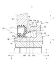
- FIG. 1 is a partial sectional view in a section along an axis for showing a schematic configuration of a sealing structure using a torsional damper and an oil seal according to a first embodiment of the present invention.
- the sealing structure using the torsional damper and the oil seal according to the first embodiment of the present invention is applied to an automobile engine.
- the direction of the arrow a (see FIG. 1) in the direction of the axis x is the outside
- the direction of the arrow b (see FIG. 1) in the direction of the axis x is the inside. More specifically, the outer side is a direction away from the engine, and the inner side is a direction approaching the engine and is the engine side.
- the direction away from the axis x is the outer peripheral side
- the direction approaching the axis x is the inner circumference.
- a sealing structure 1 using a torsional damper and an oil seal includes a damper pulley 10 as a torsional damper and an oil seal 20.
- the damper pulley 10 is fixed to one end of the crankshaft 51 of the engine by a bolt 52, and the oil seal 20 seals between the through hole 54 of the engine front cover 53 and the damper pulley 10.
- the damper pulley 10 includes a hub 11, a pulley 12 as a mass body, and a damper elastic body 13 disposed between the hub 11 and the pulley 12.
- the hub 11 is an annular member centered on the axis line x, and is a substantially disc-shaped disk portion that connects the boss portion 14 on the inner peripheral side, the rim portion 15 on the outer peripheral side, and the boss portion 14 and the rim portion 15. 16.
- the hub 11 is manufactured from, for example, a metal material by casting or the like.
- the boss part 14 is an annular part centering on the axis line x in which the through hole 14a is formed, and the disk part 16 extends in the outer peripheral direction from the outer peripheral surface of the outer part.
- the boss portion 14 includes an outer peripheral surface 14b that is a surface on the outer peripheral side of the cylindrical inner portion, and the outer peripheral surface 14b is a smooth surface, which becomes a seal surface of the oil seal 20 as will be described later.
- the rim portion 15 is an annular, more specifically cylindrical portion with the axis line x as the center, and is a portion located concentrically with respect to the boss portion 14 and on the outer peripheral side of the boss portion 14.
- a disk portion 16 extends in the inner peripheral direction from an inner peripheral surface 15a which is a surface on the inner peripheral side of the rim portion 15.
- a damper elastic body 13 is pressure-bonded to the outer peripheral surface 15 b that is the outer peripheral surface of the rim portion 15.
- the disk portion 16 extends between the boss portion 14 and the rim portion 15 and connects the boss portion 14 and the rim portion 15.
- the disc part 16 may extend in a direction perpendicular to the axis x, or may extend in a direction inclined with respect to the axis x. Further, the disk portion 16 may have a shape in which a cross section along the axis line x (hereinafter also simply referred to as “cross section”) is curved or a shape that extends straight.
- the disk portion 16 is formed with at least one window portion 16a which is a through hole penetrating the disk portion 16 between the inner side and the outer side.
- four window portions 16a are formed concentrically with respect to the axis line x at equal angular intervals in the circumferential direction (see FIG. 2).
- the window portion 16a reduces the weight of the hub 11, and thus the damper pulley 10.
- the pulley 12 is an annular member centering on the axis x, and has a shape that covers the hub 11 on the outer peripheral side.
- the inner peripheral surface 12a which is the inner peripheral surface of the pulley 12
- the inner peripheral surface 12a is positioned so as to face the outer peripheral surface 15b of the rim portion 15 with a gap in the radial direction.
- a plurality of annular v-grooves 12c are formed on the outer peripheral surface 12b, which is the outer peripheral surface of the pulley 12, so that a timing belt (not shown) can be wound.
- the damper elastic body 13 is provided between the pulley 12 and the rim portion 15 of the hub 11.
- the damper elastic body 13 is a damper rubber, and is formed by crosslinking (vulcanization) molding from a rubber-like elastic material having excellent heat resistance, cold resistance, and fatigue strength.
- the damper elastic body 13 is press-fitted between the pulley 12 and the rim portion 15 of the hub 11, and is fitted and fixed to the inner peripheral surface 12 a of the pulley 12 and the outer peripheral surface 15 b of the rim portion 15.
- the pulley 12 and the damper elastic body 13 form a damper portion, and the torsional direction natural frequency of the damper portion is a predetermined frequency region in which the torsion angle of the crankshaft 51 is maximized.
- the shaft 51 is tuned to match the natural frequency of the torsional direction. That is, the circumferential inertia mass of the pulley 12 and the torsional direction shear spring constant of the damper elastic body 13 are adjusted so that the torsional direction natural frequency of the damper portion matches the torsional direction natural frequency of the crankshaft 51. Has been.
- the damper pulley 10 has an annular hub pocket 30 that extends in the circumferential direction along the boss portion 14 of the hub 11 and that is centered on the axis x that is recessed in the direction of the disk portion 16 (outward direction). Details of the hub pocket 30 will be described later with reference to FIG.
- the damper pulley 10 is attached to one end of the crankshaft 51 in the engine. Specifically, as shown in FIG. 1, one end of the crankshaft 51 is inserted into the through hole 14a of the boss portion 14 of the hub 11, and a bolt 52 is screwed into the crankshaft 51 from the outside, so that the damper pulley 10 is cranked. It is fixed to the shaft 51. Further, a key such as a half-moon key that engages the crankshaft 51 and the boss portion 14 is provided between the crankshaft 51 and the boss portion 14, and the damper pulley 10 cannot rotate relative to the crankshaft 51. It has become.
- the oil seal 20 includes an annular metal reinforcing ring 21 centered on the axis x and an elastic body portion 22 made of an annular elastic body centered on the axis x.
- the elastic body portion 22 is integrally attached to the reinforcing ring 21.
- the metal material of the reinforcing ring 21 include stainless steel and SPCC (cold rolled steel).
- the elastic body of the elastic body portion 22 include various rubber materials. Examples of the various rubber materials include synthetic rubbers such as nitrile rubber (NBR), hydrogenated nitrile rubber (H-NBR), acrylic rubber (ACM), and fluorine rubber (FKM).
- the reinforcing ring 21 has, for example, a substantially L-shaped cross section, and includes a disk portion 21a and a cylindrical portion 21b.
- the disc portion 21a is a hollow disc-shaped portion that extends in a direction substantially perpendicular to the axis x
- the cylindrical portion 21b is a cylindrical portion that extends inward in the axis x direction from the outer peripheral end of the disc portion 21a. .
- the elastic body portion 22 is attached to the reinforcing ring 21, and in the present embodiment, the elastic body portion 22 is formed integrally with the reinforcing ring 21 so as to cover the reinforcing ring 21 from the outside and the outer peripheral side.
- the elastic body portion 22 includes a lip waist portion 23, a seal lip 24, and a dust lip 25.
- the lip waist portion 23 is a portion located in the vicinity of the inner peripheral end of the disk portion 21 a of the reinforcing ring 21, and the seal lip 24 is a portion extending inward from the lip waist portion 23. It is arranged to face the cylindrical portion 21b of the reinforcing ring 21.
- the dust lip 25 extends from the lip waist 23 in the direction of the axis x.
- the seal lip 24 has a wedge-shaped annular lip tip portion 24a having a convex cross section toward the inner peripheral side at the inner end portion.
- the lip tip portion 24a is formed so that the outer peripheral surface 14b of the boss portion 14 of the hub 11 is slidably in close contact with the outer peripheral surface 14b, and seals between the damper pulley 10 and the lip tip portion 24a. It is like that.
- a garter spring 26 that presses the seal lip 24 inward in the radial direction is fitted to the outer peripheral side of the seal lip 24.
- the dust lip 25 is a part extending from the lip waist 23 and extends outward and to the inner peripheral side.
- the dust lip 25 prevents foreign matter from entering the lip tip 24a in the used state.
- the elastic body portion 22 includes a rear cover 27 and a gasket portion 28.
- the rear cover 27 covers the disk portion 21a of the reinforcing ring 21 from the outside, and the gasket portion 28 covers the cylindrical portion 21b of the reinforcing ring 21 from the outer peripheral side.
- the oil seal 20 includes a side lip 29 that extends outward. Details of the side lip 29 will be described later with reference to FIG.
- the reinforcing ring 21 is manufactured by, for example, pressing or forging, and the elastic body portion 22 is formed by cross-linking (vulcanization) molding using a molding die. At the time of this cross-linking molding, the reinforcing ring 21 is disposed in the mold, the elastic body portion 22 is bonded to the reinforcing ring 21 by cross-linking (vulcanization) bonding, and the elastic body portion 22 is integrated with the reinforcing ring 21. Molded.
- the oil seal 20 seals the space formed between the through hole 54 of the front cover 53 and the outer peripheral surface 14b of the boss portion 14 of the damper pulley 10.
- the oil seal 20 is attached by being press-fitted into the through hole 54 of the front cover 53, and the gasket portion 28 of the elastic body portion 22 is compressed to be an inner peripheral surface that is a surface on the inner peripheral side of the through hole 54.
- 54a is in liquid-tight contact.
- the space between the oil seal 20 and the through hole 54 of the front cover 53 is sealed.
- the lip tip 24 a of the seal lip 24 is in liquid-tight contact with the outer peripheral surface 14 b of the boss 14 of the hub 11, and the oil seal 20 and the damper pulley 10 are sealed.
- FIG. 3 is a partially enlarged view of a sealing structure 1 using a torsional damper and an oil seal.
- the hub pocket 30 is a recess formed in the damper pulley 10 on the inner side of the disk portion 16 and recessed in the direction of the annular disk portion 16 extending around the outer peripheral surface 14 b of the boss portion 14.
- the hub pocket 30 includes an annular outer peripheral surface 31 that faces the outer peripheral surface 14b of the boss portion 14 on the outer peripheral side, and a bottom surface 32 that extends between the outer peripheral surface 31 and the outer peripheral surface 14b of the boss portion 14.
- the outer peripheral surface 31, the bottom surface 32, and the outer peripheral surface 14 b of the boss portion 14 are defined.
- the outer peripheral surface 31 of the hub pocket 30 increases in diameter toward the disk portion 16 direction (outward direction) in the axis line x direction, and the outer periphery increases in the direction of the disk portion 16 (outward direction) in the axis line x direction.
- An annular surface extending to the side for example, a substantially conical tapered surface.
- the hub pocket 30 may be formed by an annular ridge that extends inward from the disk portion 16 of the hub 11, and is formed by forming a recess that is recessed outward in the disk portion 16. Also good. Further, the hub pocket 30 may be a combination of these protrusions and recesses. When the hub pocket 30 is formed by an annular ridge extending inward from the disk portion 16, the inner peripheral surface of the ridge forms the outer peripheral surface 31 of the hub pocket 30. Further, when the hub pocket 30 is formed by forming a concave portion recessed outward in the disk portion 16, the outer peripheral surface of the concave portion forms the outer peripheral surface 31 of the hub pocket 30. In the present embodiment, as shown in FIG. 3, an annular ridge 33 that protrudes inward in the direction of the axis x from the disk portion 16 of the hub 11 is formed. 31 is formed to form a hub pocket 30.
- the bottom surface 32 of the hub pocket 30 may be formed by the inner surface of the disk portion 16 of the hub 11, may be formed inside the inner surface of the disk portion 16 of the hub 11, and the disk portion of the hub 11. 16 may be formed by forming a recess in the inner surface of 16.
- the diameter expansion angle ⁇ which is an angle with respect to the axis x of the outer peripheral surface 31 whose diameter is expanded as described above of the hub pocket 30 is a predetermined value.
- the diameter expansion angle ⁇ is an angle between the axis line x (a straight line parallel to the axis line x) and the outer peripheral surface 31 in the cross section.
- the expansion angle ⁇ of the outer peripheral surface 31 of the hub pocket 30 is an angle larger than 0 °, preferably 4 ° or more and 18 ° or less, more preferably 5 ° or more and 16 ° or less, and further preferably. Is 7 ° or more and 15 ° or less.
- the outer peripheral surface 31 of the hub pocket 30 is inclined toward the outer peripheral side by the diameter expansion angle ⁇ with respect to the axis x.
- the side lip 29 of the oil seal 20 extends outward, and more specifically, parallel to the axis x, or oblique to the axis x in the outer direction and the outer circumferential direction. It extends.
- the outer end 29a which is the outer end of the side lip 29, is positioned on the inner peripheral side in the radial direction with respect to the inner end 31a, which is the inner end of the outer peripheral surface 31 of the hub pocket 30, and It does not enter the inside of the hub pocket 30 in the axis line x direction (outward direction). That is, the side lip 29 of the oil seal 20 and the outer peripheral surface 31 of the hub pocket 30 do not overlap each other in the radial direction.
- the side lip 29 and the hub pocket 30 form an annular gap g1 between the outer end 29a of the side lip 29 and the inner end 31a of the outer peripheral surface 31 of the hub pocket 30.
- An annular gap g1 formed by the outer end 29a of the side lip 29 and the inner end 31a of the outer peripheral surface 31 of the hub pocket 30 forms a labyrinth seal. For this reason, in addition to the gap between the damper pulley 10 and the front cover 53, even if foreign matter such as muddy water, sand or dust enters from the outside through the window portion 16a of the disk portion 16 of the hub 11, the side lip 29 and the hub The labyrinth seal (gap g1) formed by the pocket 30 prevents the invading foreign matter from further entering the seal lip 24 side. Thereby, it can suppress that the seal lip 24 of the oil seal 20 is exposed to the foreign material which invades from the damper pulley 10 as described above.
- the foreign matter that enters from the damper pulley 10 includes foreign matter that enters from the outside through between the damper pulley 10 and the front cover 53 and foreign matter that enters from the outside through the window portion 16 a of the disk portion 16 of the hub 11. .
- the outer peripheral surface 31 of the hub pocket 30 forming the labyrinth seal (gap g1) has a shape that increases in diameter toward the outside as described above, foreign matter is further added to the labyrinth seal. Intrusion into the seal lip 24 can be more effectively suppressed.
- the outer peripheral surface 31 of the hub pocket 30 forming the labyrinth seal (gap g1) has a shape that increases in diameter toward the outside at the predetermined expansion angle ⁇ as described above, the labyrinth In the seal, it is possible to more effectively suppress foreign matters from further entering the seal lip 24 side.
- the sealing structure 1 using the torsional damper and the oil seal according to the first embodiment of the present invention has the window of the damper pulley 10 in a foreign object that enters between the damper pulley 10 and the front cover 53. It is possible to prevent the seal lip 24 of the oil seal 20 from being exposed to the foreign matter entering from the damper pulley 10 including the foreign matter entering from the portion 16a.
- the outer peripheral surface 33a (see FIG. 3), which is the outer peripheral surface of the protrusion 33 that forms the hub pocket 30, is an annular surface, for example, a conical surface, that extends toward the outer periphery in the direction of the axis x. A tapered surface may be formed.
- foreign matter that enters from the damper pulley 10 can be deposited on the outer peripheral surface 33a of the ridge 33, and the foreign matter can be prevented from reaching the oil seal 20. Further, the foreign matter accumulated on the outer peripheral surface 33 a of the protrusion 33 can be discharged downward by its own weight or by the rotation of the damper pulley 10.
- a sealing structure using an oil seal is omitted (see FIG. 4).
- the overlap amount (overlap amount) between the side lip 29 and the outer peripheral surface 31 of the hub pocket 30 in the axis x direction is 0 mm.
- the materials of the reinforcing ring 21 and the elastic body portion 22 were EPDM and FC250, respectively.
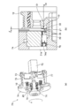
- FIG. 5 is a diagram for illustrating a schematic configuration of a sealing performance testing machine 70 used in the sealing performance evaluation test.
- FIG. 5 (a) is a partial sectional perspective view
- FIG. 5 (b) is a partially enlarged sectional view.
- the sealing performance tester 70 includes a dummy crankshaft 71 that can be rotated by a motor (not shown), a stirring blade 73 that can be rotated by a motor 72, and a dummy front cover 74.
- a cylindrical front cover 75 is attached to the dummy front cover 74, and the cover 75 accommodates the sealing structure using the torsional damper and the oil seal according to Test Examples 1 to 4 and the stirring blade 73 therein.
- a sealed space is formed around them.
- FIG. 6 is an enlarged view showing the vicinity of the hub pocket 30 of the sealing structure 1 using the torsional damper and the oil seal used for the evaluation test.
- an attachment which is an annular member in which an annular recess having an axis x as a center is formed in the hub 11 of the damper pulley 10 and a groove corresponding to the hub pocket 30 is formed in the recess.
- a damper pulley 10 in which a hub pocket 30 is formed by fixing A detachably is used.
- the side lip 29 is illustrated as overlapping the hub pocket 30.
- the stirring blade 73 is rotated by the motor 72, the dust accumulated in the cover 75 is stirred, and the amount of dust passing through the gap g1 between the side lip 29 and the hub pocket 30 ( This was done by measuring the amount of dust penetration.
- the dummy crankshaft 71 was rotated, the damper pulley 10 and the oil seal 20 were approximated to use conditions, and the ambient temperature was set to room temperature. The evaluation test was conducted for 1 hour.
- Table 1 The results of this sealing performance evaluation test are shown in Table 1 below. As shown in Table 1, comparing Test Example 4 in which the expansion angle ⁇ is 0 ° and Test Examples 1 and 2 in which the expansion angle ⁇ is greater than 0 °, the expansion angle ⁇ is greater than 0 °. It can be seen that the labyrinth seal (gap g1) formed by the hub pocket 30 and the side lip 29 has high sealing performance. Further, in Test Example 1 and Test Example 2 in which the expansion angle ⁇ is in the range of 4 ° to 18 °, the dust penetration amounts are 2.1 g and 1.0 g, respectively, and the side lip 29 and the hub pocket 30 are provided. The labyrinth seal to be formed (gap g1) has high sealing performance.
- Test Example 3 in which the diameter expansion angle ⁇ is not in the range of 4 ° or more and 18 ° or less, the dust penetration amount is 8.1 g, and the side lip 29 and the hub pocket 30 are compared with Test Examples 1 and 2.
- the labyrinth seal to be formed (gap g1) has low sealing performance.
- the sealing structure 1 using the torsional damper and the oil seal according to Test Example 1 and Test Example 2 greatly exposes the seal lip 24 of the oil seal 20 to foreign matter entering from the damper pulley 10. It was found that it can be suppressed.
- the inventor of the present invention is different from the first embodiment of the present invention in that the combination of the expansion angle ⁇ of the outer peripheral surface 31 of the hub pocket 30 and the inclination angle (inclination angle ⁇ ) (see FIG. 6) with respect to the axis x of the side lip 29 is different.
- the sealing structure 1 using the torsional damper and the oil seal according to the above form was manufactured (Test Examples 11 to 20), and the sealing performance evaluation test of the sealing structure using the torsional damper and the oil seal was performed. It was.
- a sealing structure using an oil seal A sealing structure using an oil seal.
- the evaluation test of the sealing performance of the sealing structures according to the Test Examples 11 to 20 is the same as the evaluation test for the sealing devices of the above Test Examples 1 to 4, and the test sealing device (see FIGS. 4 and 6) and the sealing performance test. The same was done using the machine 70 (see FIG. 5).
- a negative gap angle difference ⁇ indicates that the side lip 29 is inclined more than the outer peripheral surface 31 of the hub pocket 30.
- the gap angle difference ⁇ is 1.0 ° to 11.0 ° regardless of the value of the inclination angle ⁇ of the side lip 29.
- the angle difference ⁇ is 2.0 ° to 9.0 °
- the dust penetration amount can be further reduced
- the gap angle difference ⁇ is 3.0 ° to 8.0 °
- the dust penetration amount is reduced. It can be seen that it can be further reduced.
- the gap angle difference ⁇ is most preferably 7.2 ° regardless of the value of the inclination angle ⁇ of the side lip 29.
- the evaluation test of the sealing performance of the sealing structures according to the Test Examples 21 to 33 is the same as the test for the sealing device (see FIGS. 4 and 6) in the same manner as the evaluation test for the sealing devices of the Test Examples 1 to 4 described above.
- a performance tester 70 (see FIG. 5) was used in the same manner.
- the inclination angle ⁇ of the side lip 29, the gap width a which is the radial width of the gap g1, the side lip 29 and the hub pocket 30 overlap.
- the overlap amount b which is the amount that is being performed
- the interval c which is the interval in the direction of the axis x between the disk portion 16 of the damper pulley 10 and the oil seal 20, have the same value.
- the expansion angle ⁇ of the hub pocket 30, the inclination angle ⁇ of the side lip 29, the overlap amount b between the side lip 29 and the hub pocket 30, the disk portion 16 of the damper pulley 10 and the oil seal The distance c between the boss 20 and the shaft diameter d of the boss portion 14 has the same value.
- the particle size of the JIS 1 type test powder is 150 ⁇ m or more, the amount of the test powder is 5 vol%, the particle size of the JIS 3 type test powder is 5 to 75 ⁇ m, The amount is 5 vol%.
- This evaluation test is similarly performed using the test sealing device (see FIGS. 4 and 6) and the sealing performance tester 70 (see FIG. 5) in the same manner as the evaluation tests for the sealing devices in Test Examples 1 to 4 described above. went.
- the inclination angle ⁇ of the side lip 29, the gap width a of the gap g1, the overlap amount b between the side lip 29 and the hub pocket 30, the disk portion 16 of the damper pulley 10 and the oil seal 20 The distance c between them and the shaft diameter d of the boss portion 14 have the same value.
- the gap angle difference ⁇ is 2.0 ° or more and 9.0 ° or less
- the dust penetration amount is further reduced
- the gap angle difference ⁇ is 3.0 ° or more and 8.0 ° or less
- the dust penetration amount Tended to be reduced more.
- the dust penetration amount can be further reduced, and when the gap angle difference ⁇ is 3.0 ° to 8.0 °, the dust penetration amount is reduced. It can be seen that it can be further reduced. It can also be seen that the amount of dust penetration can be reduced most when the gap angle difference ⁇ is 7.2 ° in the sealing structure 1 regardless of the size of the exposed foreign matter.
- the sealing structure 2 using the torsional damper and the oil seal according to the second embodiment of the present invention is sealed using the torsional damper and the oil seal according to the above-described first embodiment of the present invention.
- the structure 1 differs from the structure 1 only in the form of an annular gap formed by the side lip 29 and the outer peripheral surface 31 of the hub pocket 30.
- the description of the configuration having the same or similar function as the sealing structure 1 using the torsional damper and the oil seal according to the first embodiment of the present invention described above is omitted, and the same reference numerals are used. Only different configurations will be described.
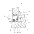
- FIG. 11 is a partially enlarged view of a cross section along the axis for showing a schematic configuration of the sealing structure 2 using the torsional damper and the oil seal according to the second embodiment of the present invention.
- the side lip 29 of the oil seal 20 has a portion on the outer end 29 a side entering the inside of the hub pocket 30, and the side lip 29 and the outer peripheral surface 31 of the hub pocket 30 are mutually connected. In the radial direction, they overlap in the direction of the axis x. That is, the side lip 29 and the outer peripheral surface 31 of the hub pocket 30 are opposed to each other in the radial direction, and an annular gap g ⁇ b> 2 is formed between the side lip 29 and the outer peripheral surface 31 of the hub pocket 30. That is, the side lip 29 and the outer peripheral surface 31 of the hub pocket 30 overlap.
- An annular gap g2 formed by the side lip 29 and the outer peripheral surface 31 of the hub pocket 30 forms a labyrinth seal. For this reason, similarly to the sealing structure 1, it is possible to suppress the foreign matter that has entered from the damper pulley 10 from further entering the seal lip 24 side. As a result, it is possible to prevent the seal lip 24 of the oil seal 20 from being exposed to foreign matter entering from the damper pulley 10, and the lip tip portion 24 a is damaged or deteriorated by biting the foreign matter, so that the sealing performance of the oil seal 20 is achieved. It is possible to suppress oil from leaking and oil leaking.
- the sealing structure 2 using the torsional damper and the oil seal according to the second embodiment of the present invention uses the torsional damper and the oil seal according to the first embodiment of the present invention.
- the seal lip 24 of the oil seal 20 can be prevented from being exposed to foreign matter entering from the damper pulley 10.
- This evaluation test is similarly performed using the test sealing device (see FIGS. 4 and 6) and the sealing performance tester 70 (see FIG. 5) in the same manner as the evaluation tests for the sealing devices in Test Examples 1 to 4 described above. went.
- the inclination angle ⁇ of the side lip 29 and the shaft diameter d of the boss portion 14 have the same value.
- the overlap amount b is set to the following values by moving the attachment A (see FIG. 6) in which the hub pocket 30 is formed in the axis x direction. Set to. Therefore, in Test Examples 61 to 70 and Test Examples 72 to 76, the distance c between the disk portion 16 of the damper pulley 10 and the oil seal 20 has a different value depending on the set overlap amount. .
- the overlap amount b 0.6 mm
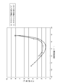
- FIG. 12 and Table 6 The results of this sealing performance evaluation test are shown in FIG. 12 and Table 6 below.
- the larger the overlap amount b the more the dust enters the interior beyond the gap g2. It has been found that the amount of the above can be reduced and the sealing performance of the sealing structure 2 can be enhanced.
- the side lip 29 formed from the member is bent by its own weight in the vertical direction when the length in the extending direction becomes longer. Accordingly, the larger the overlap amount b, the better.
- the upper limit value of the overlap amount b is, for example, a range in which the side lip 29 can maintain a desired shape with respect to gravity or other force applied in use.
- the lower limit is preferably a value between 1 mm and 1.8 mm, or 1.8 mm.
- the sealing structure 3 using the torsional damper and the oil seal according to the third embodiment of the present invention is sealed using the torsional damper and the oil seal according to the above-described first embodiment of the present invention.
- the structure for forming the hub pocket 30 is different from the structure 1.
- the description of the configuration having the same or similar function as the sealing structure 1 using the torsional damper and the oil seal according to the first embodiment of the present invention described above is omitted, and the same reference numerals are used. Only different configurations will be described.
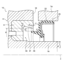
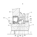
- FIG. 13 is a partially enlarged sectional view in a section along an axis for showing a schematic configuration of a sealing structure 3 using a torsional damper and an oil seal according to a third embodiment of the present invention.
- the outer peripheral surface 31 and the bottom surface 32 of the hub pocket 30 are not formed on the hub 11.
- the sealing structure 3 using a torsional damper and an oil seal has an attached ring member 40 that is separate from the hub 11 attached to the damper pulley 10, and the outer circumferential surface of the hub pocket 30 is attached to the attached ring member 40. 31 and a bottom surface 32 are formed.
- the accessory ring member 40 is a hollow annular disk-shaped member centered on the axis x, and is formed so as to be fitted to the boss portion 14 of the damper pulley 10.
- a recess is formed from one side surface of the hub pocket 30.
- the outer peripheral surface 31 and the bottom surface 32 are formed.
- the attached ring member 40 includes an outer peripheral surface 40 a that is a surface on the outer peripheral side, and an inner surface that forms a fitting through hole that is inserted into the boss portion 14 in the damper pulley 10. And an inner peripheral surface 40b which is a peripheral surface.
- the accessory ring member 40 is formed with a concave portion that is recessed outwardly on a side surface 40c that is a side surface facing inward, and an outer peripheral surface 31 and a bottom surface 32 of the hub pocket 30 are formed.
- the boss portion 14 of the damper pulley 10 is formed with a stepped surface 14c that is an outer peripheral surface that continues to the outer side of the outer peripheral surface 14b.
- the stepped surface 14c has a larger diameter than the outer peripheral surface 14b, and the outer peripheral surface 14b. Sticks out beyond. Moreover, the outer peripheral surface 14b and the level
- the attached ring member 40 is attached to the boss portion 14 b with the inner peripheral surface 40 b fitted into the step surface 14 c of the boss portion 14.
- the attached ring member 40 is attached to the damper pulley 10 by the fixing member 41 so as not to be relatively movable.
- a side surface 40 d that is a side surface facing the outside of the attached ring member 40 is in contact with the side surface of the disk portion 16.
- the fixing member 41 is, for example, a bolt, a rivet, or a pin, and includes a through hole 16b that is a through hole formed in the disk portion 16 and extending in the axis x direction, a bottom surface 32 and a side surface 40d formed in the attached ring member 40.
- the accessory ring member 40 is fixed to the damper pulley 10 by engaging with a through hole 40e extending in the direction of the axis x passing therethrough.
- the through hole 16b and the through hole 40e are screw holes, and the fixing member 41, which is a bolt, is screwed into the screw hole, whereby the attached ring member 40 is fixed to the damper pulley 10. Is done.
- the fixing member 41 is a pin or a rivet
- the fixing member 41 is fitted or engaged with the through hole 16 b and the through hole 40 e, and the attached ring member 40 is fixed to the damper pulley 10.
- the fixing method of the attached ring member 40 is not limited to the above-described one, and the fixing member 41 may realize other known applicable fixing methods. Since the attached ring member 40 is fixed to the damper pulley 10 by the fixing member 41, it is firmly fixed.
- the material of the attached ring member 40 may be a metal material or a resin material, such as stainless steel or ABS resin.
- the resin material of the accessory ring 40 is preferably a resin that can withstand the ambient temperature of the use environment such as the engine room.
- the above-described sealing structure 3 using the torsional damper and oil seal according to the third embodiment of the present invention is sealed using the torsional damper and oil seal according to the first embodiment of the present invention.
- the same operational effects as those of the structure 1 can be obtained, and the exposure of the seal lip 24 of the oil seal 20 to the foreign matter entering from the damper pulley 10 can be suppressed.
- the outer peripheral surface 31 and the bottom surface 32 of the hub pocket 30 are formed in the attached ring member 40.
- the hub pocket 30 can be easily processed.
- the hub pocket 30 is formed in the hub 11, and the hub pocket 30 cuts the hub 11 formed by casting. It is formed by doing.
- the hub 11 is heavy, and it is necessary to work on the hub pocket 30 so that the cutting tool and the boss portion 14 do not interfere with each other.
- the sealing structure 1 using a torsional damper and an oil seal 1 2 it is difficult to process the hub pocket 30.
- the outer peripheral surface 31 and the bottom surface 32 of the hub pocket 30 are processed into an annular member separate from the hub 11 to produce the attached annular member 40, Since the accessory pocket member 40 is attached to the damper pulley 10 to form the hub pocket 30, the processing of the hub pocket 30 can be facilitated. In particular, the processing of the outer peripheral surface 31 that is the inclined surface of the hub pocket 30 can be facilitated.
- the step surface protruding outward in the outer peripheral surface of the outer peripheral surface 14b in the boss portion 14 of the damper pulley 10. 14c is formed, and the attached ring member 40 is fitted to the step surface 14c. For this reason, it is possible to prevent damage to the outer peripheral surface 14b, which is the lip sliding surface with which the lip tip 24a of the seal lip 24 comes into contact, when the attachment ring member 40 is fitted.
- the sealing structure 4 using the torsional damper and the oil seal according to the fourth embodiment of the present invention is sealed using the torsional damper and the oil seal according to the above-described third embodiment of the present invention.
- the structure 3 differs from the structure 3 only in the form of an annular gap formed by the side lip 29 and the outer peripheral surface 31 of the hub pocket 30.
- the sealing structure 4 using the torsional damper and the oil seal according to the fourth embodiment of the present invention uses the torsional damper and the oil seal according to the second embodiment of the present invention described above.
- the structure for forming the hub pocket 30 is different from that of the sealing structure 2, and has an attached ring member 40.
- FIG. 14 is a partially enlarged sectional view in a section along the axis for showing a schematic configuration of a sealing structure 4 using a torsional damper and an oil seal according to a fourth embodiment of the present invention.
- the sealing structure 4 using the torsional damper and the oil seal is similar to the sealing structure 2 using the torsional damper and the oil seal according to the second embodiment of the present invention.
- a portion of the side lip 29 of the oil seal 20 on the outer end 29a side enters the inside of the hub pocket 30, and the side lip 29 and the outer peripheral surface 31 of the hub pocket 30 are in the radial direction and in the axis x direction. Overlapping (overlapping).
- the side lip 29 and the outer peripheral surface 31 of the hub pocket 30 are opposed to each other in the radial direction, and an annular gap g2 is formed between the side lip 29 and the outer peripheral surface 31 of the hub pocket 30, and the labyrinth A seal is formed.
- the outer peripheral surface 31 of the attached ring member 40 extends longer inward so that the side lip 29 and the outer peripheral surface 31 of the hub pocket 30 overlap.
- the attachment position of the attachment ring member 40 is located inside the attachment position of the attachment ring member 40 in the sealing structure 3 using the torsional damper and the oil seal according to the third embodiment of the present invention. It has become.
- the side lip 29 extends longer on the outside.
- the sealing structure 4 using the torsional damper and oil seal according to the fourth embodiment of the present invention having the above-described configuration is the torsional damper and oil according to the second and third embodiments of the present invention.
- the same effect as the sealing structures 2 and 3 using the seal can be obtained.
- the sealing structure 4 using the torsional damper and the oil seal according to the fourth embodiment of the present invention is the torsional damper and the oil seal according to the second and third embodiments of the present invention.
- FIG. 15 is a sectional view showing a schematic structure of a first modified example of the attached ring member 40 in the sealing structures 3 and 4 using the torsional damper and the oil seal according to the third and fourth embodiments of the present invention. It is.
- the outer peripheral surface 40 a forms an annular surface that expands toward the outer periphery as it goes inward in the axis x direction, for example, a conical tapered surface.
- the foreign matter accumulated on the outer peripheral surface 40 a of the attached ring member 40 ′ can be discharged downward by its own weight or by the rotation of the damper pulley 10.
- FIG. 15 a state in which the attached ring member 40 ′ according to the first modification is attached to the sealing structure 3 using the torsional damper and the oil seal is illustrated, but according to the first modification.
- the accessory ring member 40 ′ can be applied in a sealing structure 4 using a torsional damper and an oil seal, similarly to the accessory ring member 40. Even when the accessory ring member 40 ′ according to this modification is used, the same as the sealing structures 3 and 4 using the torsional damper and the oil seal according to the third and fourth embodiments of the present invention. The effect of can be produced.
- the sealing structure 5 using the torsional damper and the oil seal according to the fifth embodiment of the present invention is sealed using the torsional damper and the oil seal according to the above-described first embodiment of the present invention.
- the structure for forming the hub pocket 30 is different from the structure 1.
- the description of the configuration having the same or similar function as the sealing structure 1 using the torsional damper and the oil seal according to the first embodiment of the present invention described above is omitted, and the same reference numerals are used. Only different configurations will be described.
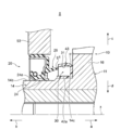
- FIG. 16 is a partially enlarged sectional view in a section along the axis for showing a schematic configuration of a sealing structure 5 using a torsional damper and an oil seal according to a fifth embodiment of the present invention.
- the hub pocket 30 is not formed in the hub 11 in the damper pulley 10 in the sealing structure 5 using a torsional damper and an oil seal.
- the sealing structure 5 using a torsional damper and an oil seal has an attached ring member 42 that is separate from the hub 11 attached to the damper pulley 10, and a hub pocket 30 is formed in the attached ring member 42. ing.
- the accessory ring member 42 is a hollow annular member centered on the axis x, and is formed so as to be fitted to the boss portion 14 of the damper pulley 10.
- a recess is formed from one side surface of the hub pocket 30. Is formed.
- the attached ring member 42 includes a cylindrical portion 42 a that is a cylindrical portion centered on the axis x, and an outer peripheral side in the radial direction from the outer end portion of the cylindrical portion 42 a. It has a disk part 42b that is a disk-shaped part that extends, and an outer peripheral part 42c that is a part that extends inward from the outer edge of the disk part 42b.
- the accessory ring member 42 is made of a metal material, and one metal member, for example, a metal plate is pressed and formed into the accessory ring member 42.
- the cylindrical part 42a, the disk part 42b, and the outer peripheral part 42 are integrally formed from the same material, and have the same or substantially the same thickness.
- the metal material of the attached ring member 42 include stainless steel and SPCC (cold rolled steel).
- the cylindrical portion 42a, the disc portion 42b, and the outer peripheral portion 42c define a space to form the hub pocket 30.
- the inner peripheral surface of the outer peripheral portion 42c forms the outer peripheral surface 31 of the hub pocket 30, and the outer peripheral portion 42c has the same angle (inclined) as the outer peripheral surface 31 of the hub pocket 30 with respect to the axis x. Inclined at an angle ⁇ ).
- the inner surface of the disk portion 42 b forms the bottom surface 32 of the hub pocket 30, and the outer peripheral surface 42 d that is the outer peripheral surface of the cylindrical portion 42 a is on the inner peripheral side facing the outer peripheral surface 31 of the hub pocket 30. A surface is formed.
- the cylindrical portion 42a of the attached ring member 42 is formed so as to be fitted to the boss portion 14 of the damper pulley 10, and when the attached ring member 42 is attached to the boss portion 14, the inner peripheral side of the cylindrical portion 42a.
- the inner peripheral surface 42e which is the surface of the boss portion 14 is in close contact with the outer peripheral surface 14b of the boss portion 14.
- the attached ring member 42 is attached to the hub 11 of the damper pulley 10 so that the cylindrical portion 42 a is fitted to the boss portion 14 so as not to move relative to the hub 11.
- the disk part 42b of the attached ring member 42 may be in contact with the disk part 16 of the hub 11 or may be separated by a predetermined interval.
- the cylindrical portion 42a of the attached ring member 42 extends inward to the lip tip portion 24a of the oil seal 20 or beyond the lip tip portion 24a, and the outer peripheral surface of the cylindrical portion 42a. 42d slidably contacts the lip tip 24a.
- the outer peripheral surface 42d of the cylindrical portion 42a of the attached ring member 42 is not the lip slide of the oil seal 20 but the outer peripheral surface 14b of the boss portion 14. A moving surface is formed.
- the outer peripheral surface 42d of the cylindrical portion 42a is formed by a process such as polishing or coating. In the present embodiment, it is possible to omit a process (processing or the like) for making the outer peripheral surface 14b of the boss portion 14 a lip sliding surface.
- the sealing structure 5 using the torsional damper and oil seal according to the fifth embodiment of the present invention described above is sealed using the torsional damper and oil seal according to the first embodiment of the present invention.
- the same operational effects as those of the structure 1 can be obtained, and the exposure of the seal lip 24 of the oil seal 20 to the foreign matter entering from the damper pulley 10 can be suppressed.
- the hub pocket 30 is formed in the attached ring member 42.
- the processing of the hub pocket 30 can be facilitated.
- the sealing structure 6 using the torsional damper and the oil seal according to the sixth embodiment of the present invention is sealed using the torsional damper and the oil seal according to the above-described fifth embodiment of the present invention.
- the structure 5 differs from the structure 5 only in the form of an annular gap formed by the side lip 29 and the outer peripheral surface 31 of the hub pocket 30.
- the sealing structure 6 using the torsional damper and the oil seal according to the sixth embodiment of the present invention uses the torsional damper and the oil seal according to the second embodiment of the present invention described above.
- the structure for forming the hub pocket 30 is different from that of the sealing structure 2, and has the attached ring member 42.
- FIG. 17 is a partial enlarged cross-sectional view along the axis for showing a schematic configuration of a sealing structure 6 using a torsional damper and an oil seal according to a sixth embodiment of the present invention.
- the sealing structure 6 using the torsional damper and the oil seal is similar to the sealing structure 2 using the torsional damper and the oil seal according to the second embodiment of the present invention.
- a portion of the side lip 29 of the oil seal 20 on the outer end 29a side enters the inside of the hub pocket 30, and the side lip 29 and the outer peripheral surface 31 of the hub pocket 30 are in the radial direction and in the axis x direction. Overlapping (overlapping).
- the side lip 29 and the outer peripheral surface 31 of the hub pocket 30 are opposed to each other in the radial direction, and an annular gap g2 is formed between the side lip 29 and the outer peripheral surface 31 of the hub pocket 30, and the labyrinth A seal is formed.
- the outer peripheral portion 42c of the attached ring member 42 extends longer inward so that the side lip 29 and the outer peripheral surface 31 of the hub pocket 30 overlap.
- the attachment position of the attachment ring member 42 is located inside the attachment position of the attachment ring member 42 in the sealing structure 5 using the torsional damper and the oil seal according to the fifth embodiment of the present invention. It has become.
- the side lip 29 extends longer on the outside.
- the sealing structure 6 using the torsional damper and oil seal according to the sixth embodiment of the present invention having the above-described configuration is the torsional damper and oil according to the second and fifth embodiments of the present invention.
- the same effects as the sealing structures 2 and 5 using the seal can be obtained.
- the sealing structure 6 using the torsional damper and the oil seal according to the sixth embodiment of the present invention is the torsional damper and the oil seal according to the second and fifth embodiments of the present invention.
- FIG. 18 is a sectional view showing a schematic structure of a first modified example of the attached ring member 42 in the sealing structures 5 and 6 using the torsional damper and the oil seal according to the fifth and sixth embodiments of the present invention. It is.
- the attached ring member 43 according to the first modification has a cylindrical portion 42 a shorter than the attached ring member 42, and the cylindrical portion 42 a has a lip sliding surface on the outer peripheral surface. Not formed.
- the outer peripheral surface 14b of the boss portion 14 of the damper pulley 10 forms a lip sliding surface, and the processing of the outer peripheral surface 14b to the lip sliding surface ( Processing etc.) cannot be omitted.
- the boss portion 14 of the damper pulley 10 is formed with a stepped surface 14c that is an outer peripheral surface that continues to the outer side of the outer peripheral surface 14b. Is preferred.
- the step surface 14c has a larger diameter than the outer peripheral surface 14b and protrudes outward from the outer peripheral surface 14b.
- the attached ring member 42 is fixed to the boss portion 14 by fitting the cylindrical portion 42 a to the step surface 14 c of the boss portion 14. Thereby, when the attachment ring member 43 is fitted, it is possible to prevent damage to the outer peripheral surface 14b, which is the lip sliding surface with which the lip tip 24a of the seal lip 24 comes into contact.
- the attachment ring member 43 according to the first modification is attached to the sealing structure 5 using the torsional damper and the oil seal is illustrated, but the attachment according to the first modification is illustrated.
- the ring member 43 can be applied in the sealing structure 6 using a torsional damper and an oil seal similarly to the attached ring member 42.
- the boss portion 14 of the damper pulley 10 is formed with a step surface 14c that is an outer peripheral surface that continues to the outer side of the outer peripheral surface 14b.
- FIG. 19 is a sectional view showing a schematic structure of a second modification of the attached ring member 42 in the sealing structures 5 and 6 using the torsional damper and the oil seal according to the fifth and sixth embodiments of the present invention. It is. As shown in FIG. 19, the attached ring member 44 according to the second modification does not have the cylindrical portion 42a with respect to the attached ring member 42, and the attached ring member 44 forms a lip sliding surface. Not done. For this reason, when using the attached ring member 44 according to the present modification, the outer peripheral surface 14b of the boss portion 14 of the damper pulley 10 forms a lip sliding surface as in the case of using the attached ring member 43. Processing (processing or the like) on the lip sliding surface of the surface 14b cannot be omitted.
- the attached ring member 44 is fitted to the boss portion 14 and fixed to the hub 11 at an inner peripheral end 42f which is an end portion on the inner peripheral side of the disk portion 42b.
- a stepped surface 14 c that is an outer peripheral surface continuing outward from the outer peripheral surface 14 b is formed on the boss portion 14 of the damper pulley 10.
- the step surface 14c has a larger diameter than the outer peripheral surface 14b and protrudes outward from the outer peripheral surface 14b.
- the attached ring member 44 is fixed to the boss portion 14 by being fitted to the step surface 14c of the boss portion 14 at the inner peripheral end 42f of the disk portion 42b. Thereby, it is possible to prevent damage to the outer peripheral surface 14b, which is the lip sliding surface with which the lip tip 24a of the seal lip 24 comes into contact, when the attachment ring member 44 is fitted.
- the attached ring member 44 when the attached ring member 44 according to this modification is used, as shown in FIG. 19, the attached ring member 44 is clamped between the boss portion 14 and the disk portion 16 of the hub 11 of the damper pulley 10.
- An annular protrusion 16d may be provided.
- the attached ring member 44 can be firmly fixed by the step surface 14c of the boss portion 14 and the inner surface of the protruding portion 16d.
- the protruding portion 16d may be provided on the disk portion 16 of the hub 11 when the above-described attached ring member 43 is used.
- FIG. 19 a state in which the attachment ring member 44 according to the second modification is attached to the sealing structure 5 using the torsional damper and the oil seal is illustrated, but the attachment according to the second modification is illustrated.
- the ring member 44 can be used in the sealing structure 6 using a torsional damper and an oil seal, similarly to the attached ring member 42.
- the boss portion 14 of the damper pulley 10 is formed with a stepped surface 14c that is an outer peripheral surface that continues to the outer side of the outer peripheral surface 14b.
- the sealing structure 7 using the torsional damper and oil seal according to the seventh embodiment of the present invention is sealed using the torsional damper and oil seal according to the above-described first embodiment of the present invention.
- the structure for forming the hub pocket 30 is different from the structure 1.
- the description of the configuration having the same or similar function as the sealing structure 1 using the torsional damper and the oil seal according to the first embodiment of the present invention described above is omitted, and the same reference numerals are used. Only different configurations will be described.
- FIG. 20 is a partial enlarged cross-sectional view along the axis for showing a schematic configuration of a sealing structure 7 using a torsional damper and an oil seal according to a seventh embodiment of the present invention.
- the damper pulley 10 in the sealing structure 7 using the torsional damper and the oil seal is the same as the sealing structure 5 using the torsional damper and the oil seal according to the fifth embodiment.
- the hub pocket 30 is not formed in the hub 11 of the damper pulley 10.
- the sealing structure 7 using a torsional damper and an oil seal has an attached ring member 45 separate from the hub 11 attached to the damper pulley 10, and a hub pocket 30 is formed in the attached ring member 45. ing.
- the accessory ring member 45 is a hollow annular member centering on the axis line x, and is formed so as to be fitted to the boss portion 14 of the damper pulley 10.
- a recess is formed from one side surface of the hub pocket 30. Is formed.
- the attached ring member 45 includes an annular elastic flange 46 centered on an axis x formed from an elastic body, and an annular centered on an axis x formed from a metal material.
- Metal ring portion 47 is a hollow annular member centering on the axis line x, and is formed so as to be fitted to the boss portion 14 of the damper pulley 10.
- the metal ring portion 47 includes a cylindrical portion 47a that is a cylindrical portion centered on the axis x, a disc portion 47b that is a disc-shaped portion extending radially outward from an outer end portion of the cylindrical portion 47a, and It has an outer peripheral portion 47c that is a portion that is bent from the end portion on the outer peripheral side of the disk portion 47b and extends inward.
- the metal ring portion 47 is formed of a metal material as described above, and is formed by pressing one metal member, for example, a metal plate.
- the cylindrical portion 47a, the disc portion 47b, and the outer peripheral portion 47c are integrally formed from the same material, and have the same or substantially the same thickness. Examples of the metal material of the metal ring portion 47 include stainless steel and SPCC (cold rolled steel).
- the elastic flange portion 46 is made of, for example, a rubber material.
- the rubber material of the elastic flange portion 46 include the rubber elastic body of the elastic body portion 22 of the oil seal 20 described above.
- the elastic flange portion 46 is an annular member extending in the direction of the axis x, is attached to the outer peripheral side of the metal ring portion 47, and extends inward from the disk portion 47 b of the metal ring portion 47. ing.
- the outer peripheral portion 47 c of the metal ring portion 47 and the outer peripheral end portion of the disc portion 47 b and the vicinity thereof are embedded from the outside into the elastic flange portion 46, and the elastic flange portion 46 is held by the attached ring member 45. Has been.
- the inner peripheral surface of the elastic flange portion 46 forms the outer peripheral surface 31 of the hub pocket 30, and the outer peripheral surface 31 extends at an inclination angle ⁇ with respect to the axis x as described above.
- the elastic flange portion 46 is formed by cross-linking molding, and is bonded to the metal ring portion 47 by cross-linking during the cross-linking molding.
- the cylindrical portion 47a of the metal ring portion 47, the disk portion 47b of the metal ring portion 47, and the elastic flange portion 46 define a space to form the hub pocket 30.
- the inner surface of the disk portion 47 b of the metal ring portion 47 forms the bottom surface 32 of the hub pocket 30, and the outer peripheral surface 47 d that is the outer peripheral surface of the cylindrical portion 47 a of the metal ring portion 47 is the hub pocket 30.
- An inner peripheral surface facing the outer peripheral surface 31 is formed.
- the cylindrical portion 47a of the metal ring portion 47 is formed to be fitted to the boss portion 14 of the damper pulley 10, and the inner ring side of the cylindrical portion 47a in a state where the attached ring member 45 is attached to the boss portion 14.
- the inner peripheral surface 47e which is the surface of the boss, is in close contact with the outer peripheral surface 14b of the boss portion 14.
- the attached ring member 45 is attached to the hub 11 of the damper pulley 10 so as not to be relatively movable, with the cylindrical portion 47 a of the metal ring portion 47 fitted into the boss portion 14. At this time, the disk part 47b of the metal ring part 47 is in contact with the disk part 16 of the hub 11, or is separated by a predetermined interval.
- the cylindrical portion 47a of the metal ring portion 47 extends inward to the lip tip portion 24a of the oil seal 20 or beyond the lip tip portion 24a, and the outer peripheral surface of the cylindrical portion 47a. 47d is slidably in contact with the lip tip 24a.
- the outer peripheral surface 47d of the cylindrical portion 47a of the metal ring portion 47 of the attached ring member 45 is not oil but the outer peripheral surface 14b of the boss portion 14. A lip sliding surface of the seal 20 is formed.
- the outer peripheral surface 47d of the cylindrical portion 47a is formed by a process such as polishing or coating, similar to the above-described accessory ring member 42 (FIG. 16).
- processing for making the outer peripheral surface 14b of the boss portion 14 a lip sliding surface may be omitted. It can.
- the outer peripheral portion 47 c of the metal ring portion 47 has a length capable of holding at least the elastic flange portion 46.
- the sealing structure 7 using the torsional damper and the oil seal according to the seventh embodiment of the present invention described above is sealed using the torsional damper and the oil seal according to the first embodiment of the present invention.
- the same operational effects as those of the structure 1 can be obtained, and the exposure of the seal lip 24 of the oil seal 20 to the foreign matter entering from the damper pulley 10 can be suppressed.
- the attached ring member 45 in which the hub pocket 30 is formed has an elastic body formed of an elastic body.
- An outer peripheral surface 31 of the hub pocket 30 is formed by the flange portion 46.
- the outer peripheral surface 31 can be accurately formed so that the diameter expansion angle ⁇ of the outer peripheral surface 31 of the hub pocket 30 becomes a desired value. This is because molding with a rubber material can improve the dimensional accuracy of a molded product rather than pressing a metal material.
- the elastic flange portion 46 is formed of an elastic body such as a rubber material so as to absorb the impact.
- the side lip 29 can be made difficult to be damaged.
- the metal member press molding if the shape of the metal member becomes complicated, residual stress is generated in the metal member, and the entire metal member is easily distorted.
- the metal formed from the metal material The shape of the ring portion 47 can be simplified, and the forming accuracy (dimensional accuracy) of the metal ring portion 47 can be increased.
- the hub pocket 30 is formed in the attached ring member 45. As with the sealing structure 3 using the torsional damper and the oil seal according to the third embodiment, the processing of the hub pocket 30 can be facilitated.
- the side lip 29 of the oil seal 20 does not enter the hub pocket 30, but the side lip 29 has a portion on the outer end 29 a side.
- the side lip 29 and the outer peripheral surface 31 of the hub pocket 30 may enter the inside of the hub pocket 30 and overlap each other in the radial direction in the axis line x direction. That is, like the above-described sealing structures 2 and 6 (FIGS. 11 and 17), the side lip 29 and the outer peripheral surface 31 of the hub pocket 30 face each other in the radial direction, and the outer peripheral surface of the side lip 29 and the hub pocket 30 An annular gap g ⁇ b> 2 may be formed with respect to 31.
- the shape of the metal ring portion 47 of the attached ring member 45 is not limited to the above shape, and for example, the attached ring member 43 shown in FIG. As described above, the cylindrical portion 47a may not extend to the seal lip 24a, and the boss portion 14 of the damper pulley 10 may form a lip sliding surface. Also in this case, as shown in FIG. 18, the boss portion 14 of the damper pulley 10 is formed with a stepped surface 14c that is an outer peripheral surface continuing to the outer peripheral surface 14b on the outside, and the attached ring member 45 is fitted to the stepped surface 14c. It is preferable.
- the shape of the metal ring portion 47 of the attached annular member 45 may be a shape that does not have the cylindrical portion 47a like the attached ring member 44 shown in FIG.
- the shape of the hub 11 of the damper pulley 10 is preferably a shape having a protruding portion 16d and a step surface 14c as shown in FIG.
- the sealing structure 8 using the torsional damper and the oil seal according to the eighth embodiment of the present invention is sealed using the torsional damper and the oil seal according to the above-described first embodiment of the present invention.
- the structure of the gap g1 is different from the structure 1.
- the description of the configuration having the same or similar function as the sealing structure 1 using the torsional damper and the oil seal according to the first embodiment of the present invention described above is omitted, and the same reference numerals are used. Only different configurations will be described.
- FIG. 21 is a partially enlarged cross-sectional view taken along the axis for showing a schematic configuration of a sealing structure 8 using a torsional damper and an oil seal according to an eighth embodiment of the present invention.
- a sealing structure 8 using a torsional damper and an oil seal includes an oil seal 60 instead of the oil seal 20 in the above-described sealing structure 1 and forms a gap g1.
- An annular member 61 is provided.
- the oil seal 60 differs from the oil seal 20 in that it does not have the side lip 29 and is not directly attached to the through hole 54 of the front cover 53.
- the ring member 61 is a hollow annular member centering on the axis x, and forms an outer peripheral surface that is inclined at the same inclination angle ⁇ (see FIG. 6) as the outer peripheral surface of the side lip 29 of the oil seal 20 described above. It has a protrusion 62 as a side lip that can be fitted into the through hole 54 of the front cover 53.
- the ring member 61 includes a cylindrical fitting portion 63 centering on the axis x, and a disk-like support portion 64 extending from the outer end of the fitting portion 63 to the inner peripheral side.
- the projection 62 extends from the inner peripheral end of the support portion 64 to the opposite side of the fitting portion 63 and extends toward the hub pocket 30.
- the fitting portion 63 is formed to be able to fit into the through hole 54 of the front cover 53, and when the fitting portion 63 is fitted into the through hole 54 of the front cover 53, It is formed so as to be in close contact with the inner peripheral surface 54 a of the through hole 54.
- the protrusion 62 is an annular portion centered on the axis x, and forms a gap g1 between the outer end 62a, which is the outer end, and the inner end 31a of the outer peripheral surface 31 of the hub pocket 30. .
- the ring member 61 is made of a metal material or a resin material, and examples of the metal material include stainless steel and SPCC (cold rolled steel). When the sealing structure 8 is used in an environment where rust is likely to occur, stainless steel is preferable as the metal material of the ring member 61.
- the ring member 61 is formed separately from the oil seal 60 by press working or resin molding. As shown in FIG. 21, the support member 64 of the ring member 61 is fitted with the oil seal 60 in the ring member 61. , The fitting portion 63 is fitted into the through hole 54 of the front cover 53, and the ring member 61 is fitted to the front cover 53. Thereby, the oil seal 60 and the ring member 61 are attached to the front cover 53, and the gap g1 is formed.
- the projecting portion 62 of the ring member 61 is not limited to the shape that does not enter the inside of the hub pocket 30, and the portion on the outer end 62 a side of the projecting portion 62, like the side lip 29 of the sealing structure 2, 30, the protrusion 62 and the outer peripheral surface 31 of the hub pocket 30 may overlap each other in the radial direction in the axis x direction. That is, similar to the above-described sealing structure 2 (FIG. 11), the protrusion 62 and the outer peripheral surface 31 of the hub pocket 30 are opposed to each other in the radial direction, and between the protrusion 62 and the outer peripheral surface 31 of the hub pocket 30. An annular gap g2 may be formed.
- the sealing structure 8 using the torsional damper and the oil seal according to the eighth embodiment of the present invention uses the torsional damper and the oil seal according to the above-described first and second embodiments of the present invention.
- the same effects as the sealed structures 1 and 2 can be obtained.
- the ring member 61 is formed of a metal material or a resin material, has higher rigidity than a member formed of a rubber material, and the protruding portion 62 is not easily deformed by its own weight. For this reason, when the gap 62 is formed between the protrusion 62 and the hub pocket 30, the protrusion 62 that is bent by its own weight can be lengthened. For this reason, the overlap amount b between the projection part 62 and the hub pocket 30 can be increased, and the amount of foreign matter entering through the gap g2 can be reduced.
- the oil seal 60 and the ring member 61 are attached to the oil seal 20 in the sealing structures 3 to 7 using the torsional damper and the oil seal according to the third to seventh embodiments of the present invention described above. It can be applied instead.
- the damper pulley 10 the oil seals 20, 60, and the ring member
- the form 61 may be another form.
- the sealing structures 1 to 8 using the torsional damper and the oil seal according to the present embodiment are applied to an automobile engine.
- the torsional damper and the oil seal according to the present invention are used.
- the application object of the sealed structure is not limited to this, and the present invention is applicable to all configurations that can use the effects of the present invention, such as rotating shafts of other vehicles, general-purpose machines, and industrial machines. Is possible.
- the torsional damper (damper pulley 10) in the present embodiment is formed with a window portion 16a that is a through hole penetrating the disc portion 16 between the inside and the outside.
- the application object of the sealing structure using the torsional damper and the oil seal is not limited to this, and the present invention can be applied to the case where the window portion 16a is not formed.
Landscapes
- Engineering & Computer Science (AREA)
- General Engineering & Computer Science (AREA)
- Mechanical Engineering (AREA)
- Physics & Mathematics (AREA)
- Acoustics & Sound (AREA)
- Aviation & Aerospace Engineering (AREA)
- Sealing With Elastic Sealing Lips (AREA)
- Sealing Using Fluids, Sealing Without Contact, And Removal Of Oil (AREA)
- Pulleys (AREA)
Abstract
Description
本発明者は、拡径角度αが異なる上記本発明の第1の実施の形態に係るトーショナルダンパとオイルシールとを用いた密封構造1を製作し(試験例1~4)、これらのトーショナルダンパとオイルシールとを用いた密封構造1の密封性能の評価試験を行った。ただし、試験例4は、上記本発明の第1の実施の形態に係るトーショナルダンパとオイルシールとを用いた密封構造1に対して拡径角度αをα=0°としたトーショナルダンパとオイルシールとを用いた密封構造である。また、密封性能の評価の便宜上、実施例1~4においては、オイルシール20における弾性体部22のシールリップ24、ダストリップ25、及びガータースプリング26の形成を省略した(図4参照)。

表1に示すように、拡径角度αが0°である試験例4と拡径角度αが0°よりも大きい試験例1,2とを比較すると、拡径角度αが0°よりも大きいハブポケット30とサイドリップ29とが形成するラビリンスシール(間隙g1)の密封性能が高いことが分かる。また、拡径角度αが4°以上18°以下の範囲内にある試験例1及び試験例2は、ダスト侵入量が夫々2.1g及び1.0gであり、サイドリップ29及びハブポケット30が形成するラビリンスシール(間隙g1)の密封性能が高い。一方、拡径角度αが4°以上18°以下の範囲内にない試験例3は、ダスト侵入量が8.1gであり、試験例1,2と比較してサイドリップ29及びハブポケット30が形成するラビリンスシール(間隙g1)の密封性能が低い。このように、試験例1及び試験例2に係るトーショナルダンパとオイルシールとを用いた密封構造1は、ダンパプーリ10から侵入する異物にオイルシール20のシールリップ24が曝されることを大幅に抑制することができることが分かった。つまり、拡径角度αが4°以上18°以下の範囲内にあるトーショナルダンパとオイルシールとを用いた密封構造1は、ダンパプーリ10から侵入する異物にオイルシール20のシールリップ24が曝されることを大幅に抑制することができることが分かった。
本発明者は、ハブポケット30の外周面31の拡径角度αとサイドリップ29の軸線xに対する傾斜角度(傾斜角度γ)(図6参照)との組み合わせが異なる上記本発明の第1の実施の形態に係るトーショナルダンパとオイルシールとを用いた密封構造1を製作し(試験例11~20)、これらのトーショナルダンパとオイルシールとを用いた密封構造の密封性能の評価試験を行った。ただし、試験例11は、上記本発明の第1の実施の形態に係るトーショナルダンパとオイルシールとを用いた密封構造1に対して拡径角度αをα=0°としたトーショナルダンパとオイルシールとを用いた密封構造である。本試験例11~20に係る密封構造の密封性能の評価試験は、上述の試験例1~4の密封装置に対する評価試験と同様に試験用の密封装置(図4,6参照)と密封性能試験機70(図5参照)とを用いて同様に行った。
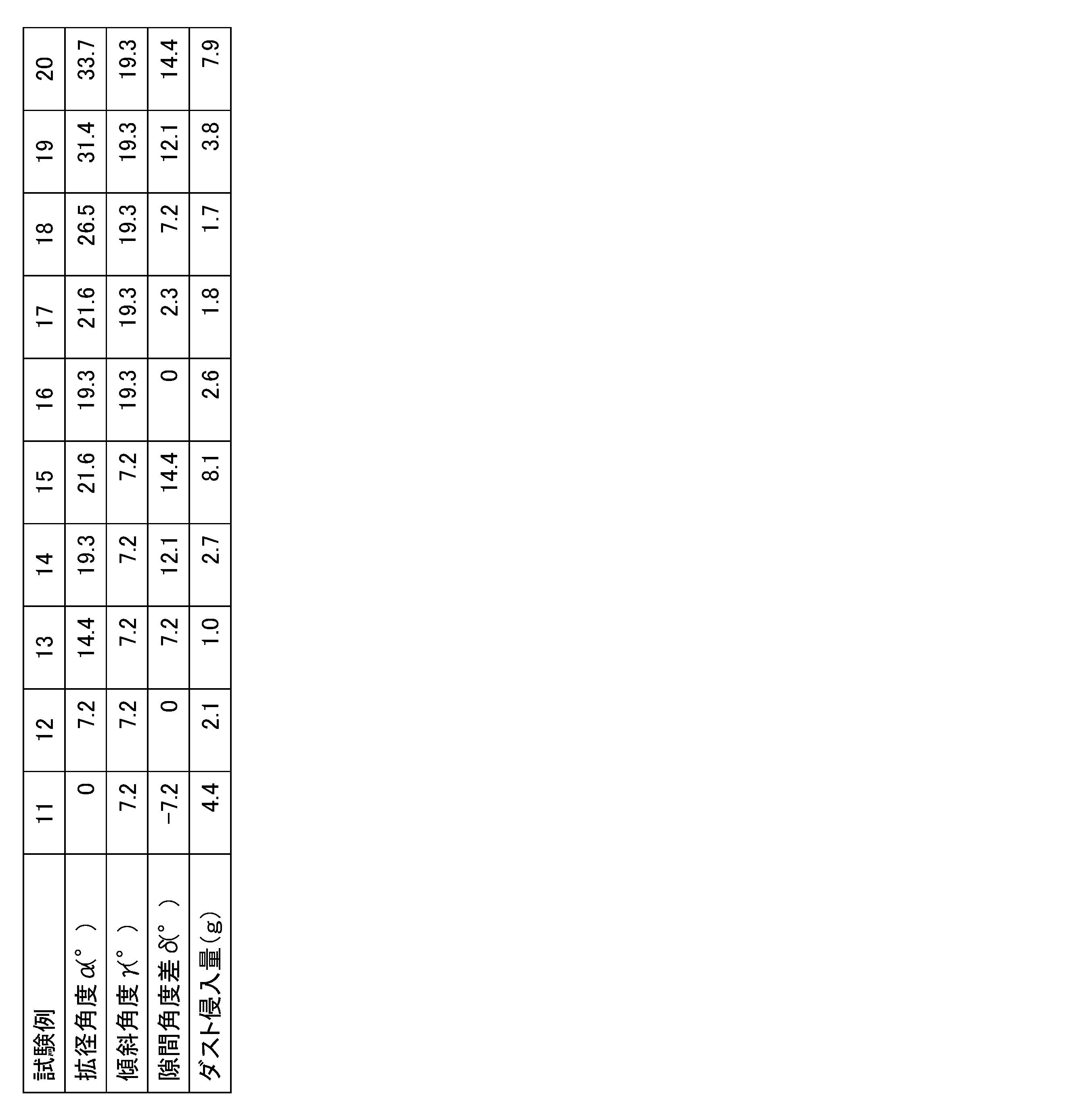
図7及び表2に示すように、本評価試験から、隙間角度差δとダスト侵入量との間に関連性があることが分かった。そして、サイドリップ29の傾斜角度γの値がγ=7.2°であってもγ=19.3°であっても、隙間角度差δが1.0°以上11.0°以下である場合、ダスト侵入量が低減され、隙間角度差δが2.0°以上9.0°以下である場合、ダスト侵入量が更に低減され、隙間角度差δが3.0°以上8.0°以下である場合、ダスト侵入量がより低減される傾向が認められた。また、サイドリップ29の傾斜角度γの値がγ=7.2°であってもγ=19.3°であっても、隙間角度差δがδ=7.2°の場合、ダスト侵入量が最も低減される傾向が認められた。この評価結果から、サイドリップ29の傾斜角度γの値に拘らず、隙間角度差δが1.0°~11.0°である場合にダスト侵入量を効果的に低減させることができ、隙間角度差δが2.0°~9.0°である場合にダスト侵入量をより低減させることができ、隙間角度差δが3.0°~8.0°である場合にダスト侵入量を更に低減させることができることが分かる。また、ダスト侵入量を低減させるためには、サイドリップ29の傾斜角度γの値に拘らず、隙間角度差δが7.2°であることが最も好ましいことが分かる。
また、本発明者は、ダンパプーリ10のボス部14の軸の直径である軸径d(図6参照)と隙間角度差δとの組み合わせが異なる上記本発明の第1の実施の形態に係るトーショナルダンパとオイルシールとを用いた密封構造1を製作し(試験例21~33)、これらのトーショナルダンパとオイルシールとを用いた密封構造の密封性能の評価試験を行った。ただし、試験例21,25,30は、上記本発明の第1の実施の形態に係るトーショナルダンパとオイルシールとを用いた密封構造1に対して拡径角度αをα=0°としたトーショナルダンパとオイルシールとを用いた密封構造である。試験例21~24においては、ボス部14の軸径dをd=35mmとし、試験例25~29においては、ボス部14の軸径dをd=42mmとし、試験例30~33においては、ボス部14の軸径dをd=50mmとした。また、本試験例21~33に係る密封構造の密封性能の評価試験は、上述の試験例1~4の密封装置に対する評価試験と同様に試験用の密封装置(図4,6参照)と密封性能試験機70(図5参照)とを用いて同様に行った。なお、本評価試験においては、夫々の軸径dの密封構造において、サイドリップ29の傾斜角度γ、間隙g1の径方向の幅である間隙幅a、サイドリップ29とハブポケット30とがオーバーラップしている量であるオーバーラップ量b、及びダンパプーリ10の円盤部16とオイルシール20との間の軸線x方向の間隔である間隔cは同じ値となっている。オーバーラップ量bはb=0であり、サイドリップ29の傾斜角度γはγ=7.2°である。
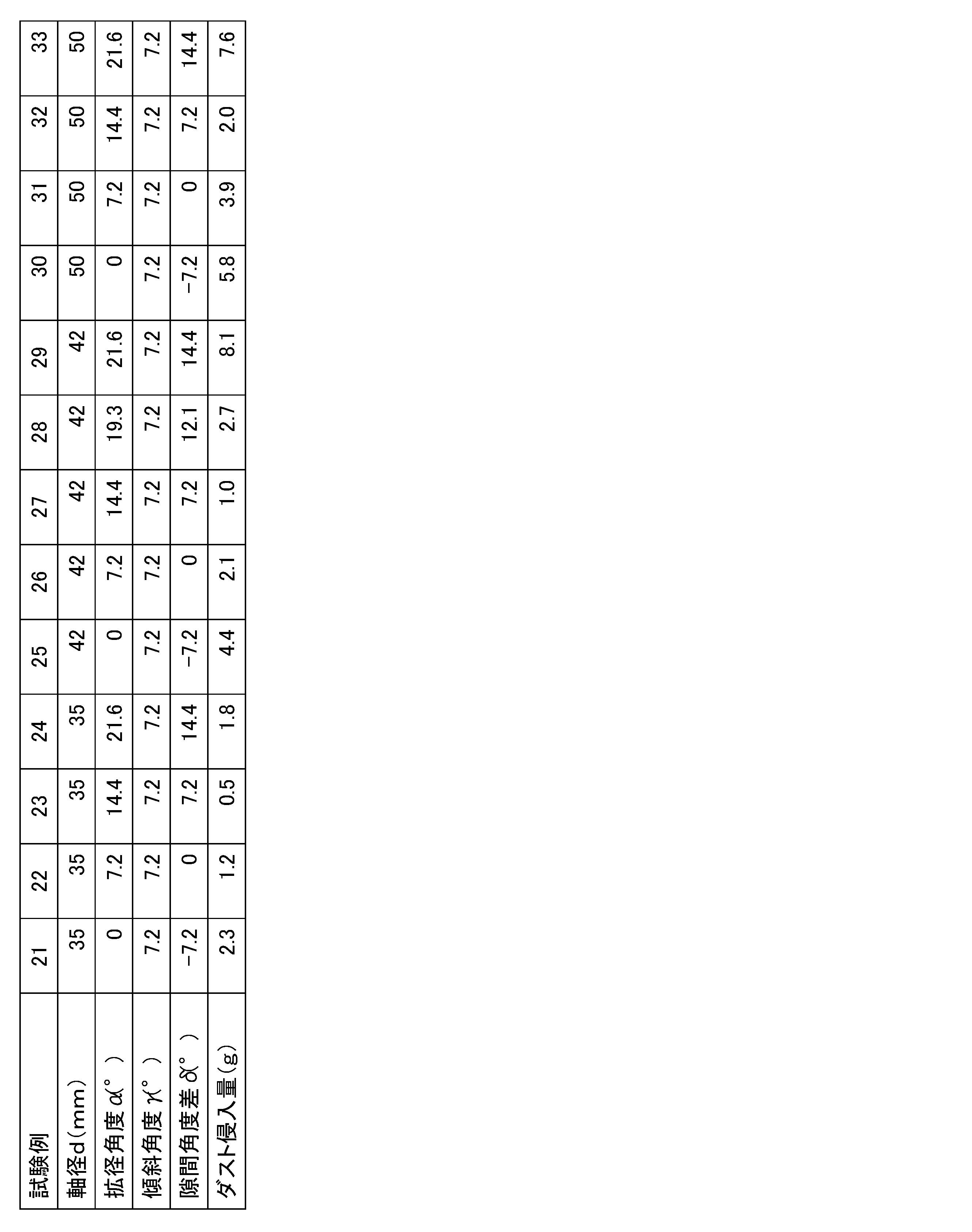
図8及び表3に示すように、本評価試験から、軸径d=35,42,50mmの各々の密封構造においても、隙間角度差δとダスト侵入量との間に、上記評価試験2と同様の傾向が認められた。つまり、軸径d=35,42,50mmの夫々の密封構造においても、隙間角度差δが1.0°以上11.0°以下である場合、ダスト侵入量が低減され、隙間角度差δが2.0°以上9.0°以下である場合、ダスト侵入量が更に低減され、隙間角度差δが3.0°以上8.0°以下である場合、ダスト侵入量がより低減される傾向が認められた。また、軸径d=35,42,50mmの夫々の密封構造においても、隙間角度差δがδ=7.2°の場合、ダスト侵入量が最も低減されることが分かった。この評価結果から、ボス部14の軸径dの値が異なる各密封構造1において、隙間角度差δが1.0°~11.0°である場合にダスト侵入量を低減させることができ、隙間角度差δが2.0°~9.0°である場合にダスト侵入量をより低減させることができ、隙間角度差δが3.0°~8.0°である場合にダスト侵入量を更に低減させることができることが分かる。また、ボス部14の軸径dの値が異なる各密封構造1において、隙間角度差δが7.2°である場合に、ダスト侵入量を最も低減させることができることが分かる。このように、ボス部14の軸径dの値に拘らず、隙間角度差δが7.2°である場合にダスト侵入量が最小となることが分かる。また、本評価試験から、間隙g1の通路面積が大きいほど、つまり軸径dが大きいほど、ダスト侵入量が大きくなることが分かった。
また、本発明者は、サイドリップ29とハブポケット30とが形成する間隙g1の間隙幅aが異なる上記本発明の第1の実施の形態に係るトーショナルダンパとオイルシールとを用いた密封構造1を製作し(試験例41~44)、これらのトーショナルダンパとオイルシールとを用いた密封構造の密封性能の評価試験を行った。また、本試験例41~44に係る密封構造の密封性能の評価試験は、上述の試験例1~4の密封装置に対する評価試験と同様に試験用の密封装置(図4,6参照)と密封性能試験機70(図5参照)とを用いて同様に行った。試験例41~44の夫々においては、ハブポケット30の拡径角度α、サイドリップ29の傾斜角度γ、サイドリップ29とハブポケット30とのオーバーラップ量b、ダンパプーリ10の円盤部16とオイルシール20との間の間隔c、及びボス部14の軸径dは同じ値となっている。なお、オーバーラップ量bはb=0であり、サイドリップ29の傾斜角度γはγ=7.2°である。
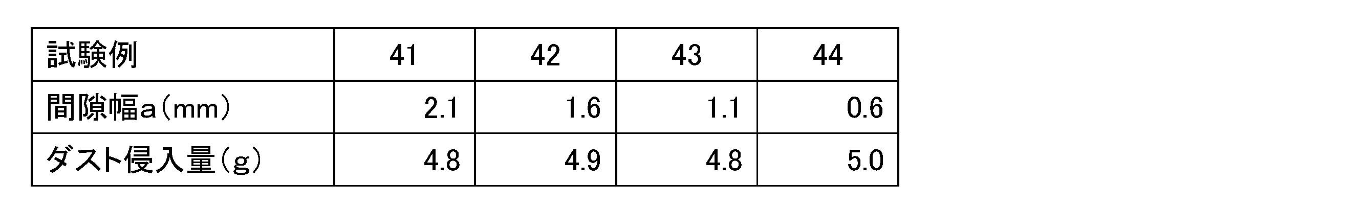
図9及び表4に示すように、試験例41~44において、ダスト侵入量に差はほとんど認められない。このように、本評価試験から、ボス部14の軸径dが一定であれば、間隙g1の間隙幅aが変化しても密封構造1の密封性能にほとんど影響が無いことが分かった。
また、本発明者は、異物の大きさの違いが上記トーショナルダンパとオイルシールとを用いた密封構造1の密封性能に与える影響について評価するために本評価試験を行った。本評価試験においては、隙間角度差δが異なる上記本発明の第1の実施の形態に係るトーショナルダンパとオイルシールとを用いた密封構造1を製作し(試験例51~60)、JIS1種及びJIS3種の2つの異なる試験用粉体を別々に用いて、密封性能の評価試験を行った。ただし、試験例51,56は、上記本発明の第1の実施の形態に係るトーショナルダンパとオイルシールとを用いた密封構造1に対して拡径角度αをα=0°としたトーショナルダンパとオイルシールとを用いた密封構造である。JIS1種の試験用粉体の粒径は150μm以上であり、試験用粉体の量は5vol%であり、JIS3種の試験用粉体の粒径は5~75μmであり、試験用粉体の量は5vol%である。本評価試験は、上述の試験例1~4の密封装置に対する評価試験と同様に試験用の密封装置(図4,6参照)と密封性能試験機70(図5参照)とを用いて同様に行った。試験例51~60の夫々においては、サイドリップ29の傾斜角度γ、間隙g1の間隙幅a、サイドリップ29とハブポケット30とのオーバーラップ量b、ダンパプーリ10の円盤部16とオイルシール20との間の間隔c、及びボス部14の軸径dは同じ値となっている。なお、オーバーラップ量bはb=0であり、サイドリップ29の傾斜角度γはγ=7.2°であり、軸径dはd=42mmである。

図10及び表5に示すように、本評価試験から、試験用粉体として粒径の小さいJIS3種を使用した場合、JIS1種を使用する場合よりもダスト侵入量は減少したが、粒径の異なるJIS1,3種を使用した場合でも、各粒径の試験用粉体に対して、隙間角度差δとダスト侵入量との間に、上記評価試験2と同様の傾向が認められた。つまり、粒径の異なるJIS1,3種の夫々を試験用粉体として使用した密封構造においても、隙間角度差δが1.0°以上11.0°以下である場合、ダスト侵入量が低減され、隙間角度差δが2.0°以上9.0°以下である場合、ダスト侵入量が更に低減され、隙間角度差δが3.0°以上8.0°以下である場合、ダスト侵入量がより低減される傾向が認められた。また、粒径の異なるJIS1,3種の夫々を試験用粉体として夫々使用した密封構造においても、隙間角度差δがδ=7.2°の場合、ダスト侵入量が最も低減されることが分かった。この評価結果から、曝される異物の大きさに拘らず、密封構造1において、隙間角度差δが1.0°~11.0°である場合にダスト侵入量を低減させることができ、隙間角度差δが2.0°~9.0°である場合にダスト侵入量をより低減させることができ、隙間角度差δが3.0°~8.0°である場合にダスト侵入量を更に低減させることができることが分かる。また、曝される異物の大きさに拘らず、密封構造1において、隙間角度差δが7.2°である場合に、ダスト侵入量を最も低減させることができることが分かる。
本発明者は、サイドリップ29とハブポケット30の外周面31とが軸線x方向に亘り重なり合う長さであるオーバーラップ量bの違いが上記トーショナルダンパとオイルシールとを用いた密封構造2の密封性能に与える影響について評価するために本評価試験を行った。本評価試験においては、各ハブポケット30の拡径角度αに対して異なるオーバーラップ量bを設定した上記本発明の第2の実施の形態に係るトーショナルダンパとオイルシールとを用いた密封構造2を製作し(試験例61~77)、密封性能の評価試験を行った。ただし、試験例72~77は、上記本発明の第2の実施の形態に係るトーショナルダンパとオイルシールとを用いた密封構造2に対して拡径角度αをα=0°としたトーショナルダンパとオイルシールとを用いた密封構造である。試験例61~65においては、ハブポケット30の拡径角度αをα=7.2°とし、試験例66~71においては、ハブポケット30の拡径角度αをα=14.4°とした。本評価試験は、上述の試験例1~4の密封装置に対する評価試験と同様に試験用の密封装置(図4,6参照)と密封性能試験機70(図5参照)とを用いて同様に行った。試験例61~74の夫々においては、サイドリップ29の傾斜角度γ、及びボス部14の軸径dは同じ値となっている。なお、傾斜角度γはγ=7.2°である。また、試験例61~70及び試験例72~76においては、ハブポケット30が形成されたアタッチメントA(図6参照)を軸線x方向において移動させることにより、オーバーラップ量bを下記の夫々の値に設定した。このため、試験例61~70及び試験例72~76においては、ダンパプーリ10の円盤部16とオイルシール20との間の間隔cが、設定されたオーバーラップ量に応じて異なる値となっている。一方、試験例71,77においては、ダンパプーリ10の円盤部16に対向するオイルシール20の弾性体部22の外側の面を切削して、間隔cの値が、試験例61,72(オーバーラップ量b=0)における間隔cの値と同一となるようにした。
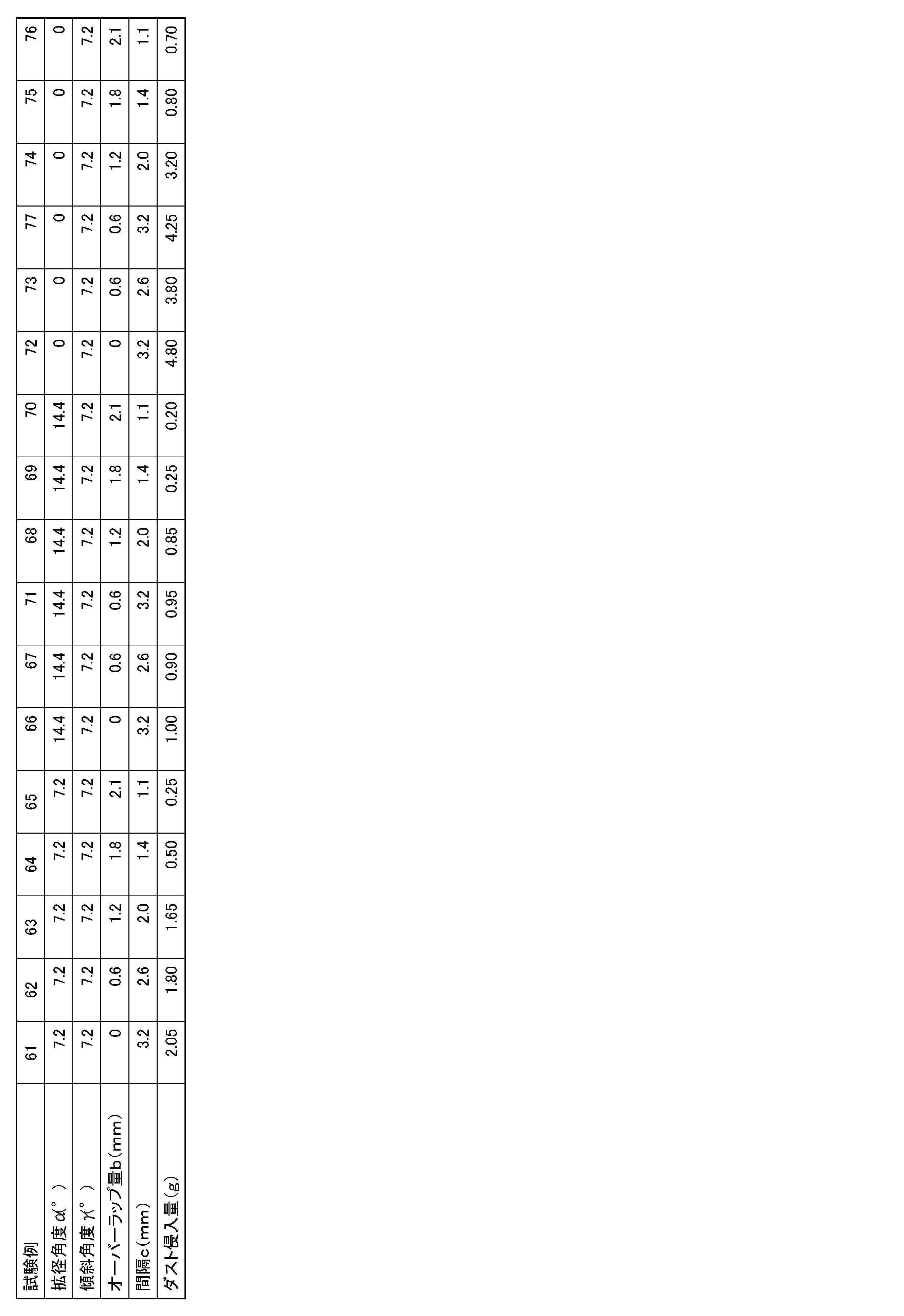
図12及び表6に示すように、本評価試験から、オーバーラップ量bとダスト侵入量との間に関連性があることが分かる。具体的には、各拡径角度αにおいて同様に、オーバーラップ量bが増加するに連れて、ダスト侵入量が減少していくことが分かる。また、図12において塗り潰した○及び△は、試験例71,77の試験結果に夫々対応しており、間隔cがオーバーラップ量bの値に応じて減少された夫々同じオーバーラップ量b(b=0.6mm)を有する対応する試験例67,73と略同等の試験結果を示している。このため、本評価試験において、ダンパプーリ10の円盤部16とオイルシール20との間の間隔cは、ダスト侵入量に影響を与えないと考えることができる。
10,100 ダンパプーリ
11,101 ハブ
12,102 プーリ
12a 内周面
12b 外周面
12c v溝
13,103 ダンパ弾性体
14,101a ボス部
14a 貫通穴
14b 外周面
14c 段差部
15,101b リム部
15a 内周面
15b 外周面
16,101c 円盤部
16a,101d 窓部
16d 突出部
20,60,110 オイルシール
21 補強環
21a 円盤部
21b 円筒部
22 弾性体部
23 リップ腰部
24,111 シールリップ
24a リップ先端部
25 ダストリップ
26 ガータースプリング
27 後方カバー
28 ガスケット部
29 サイドリップ
29a 外側端
30 ハブポケット
31 外周面
31a 内側端
32 底面
33 突条部
40,40´,42~45 付属環部材
40a 外周面
41 固定部材
42a 円筒部
42b 円盤部
42c 外周部
42d 外周面
46 弾性フランジ部
47 金属環部
51,120 クランクシャフト
52,121 ボルト
53,122 フロントカバー
54,123 貫通穴
54a 内周面
61 環部材
62 突起部
a 間隙幅
b オーバーラップ量
c 間隔
d 軸径
g1,g2 間隙(ラビリンスシール)
x 軸線
α 拡径角度
γ 傾斜角度
δ 隙間角度差
Claims (9)
- トーショナルダンパとオイルシールとを用いた密封構造であって、
前記トーショナルダンパは、ハブと、該ハブを外周において覆う軸線を中心とする環状の質量体と、前記ハブと前記質量体との間に配設されて前記ハブと前記質量体とを弾性的に接続するダンパ弾性体とを備え、前記トーショナルダンパは、前記ハブが被取付部の貫通穴に挿通されて、回転軸の一端に取り付けられ、
前記オイルシールは、前記軸線を中心とする環状のシールリップと、前記軸線を中心とする環状のサイドリップとを備え、前記被取付部の前記貫通穴に取り付けられて、前記ハブと前記被取付部の前記貫通穴との間を密封し、
前記ハブは、前記軸線を中心とする環状のボス部と、該ボス部の外周に位置する前記軸線を中心とする環状のリム部と、前記ボス部と前記リム部とを接続する前記軸線を中心とする円盤状の円盤部と、前記軸線を中心とする環状のハブポケットとを備え、
前記ハブポケットは、前記ボス部に外周側において対向する環状の外周面を備え、前記円盤部方向に凹む前記軸線を中心とする環状の凹部を形成し、
前記ハブポケットの前記外周面は、前記軸線において前記円盤部方向に向うに連れて拡径しており、
前記オイルシールにおいて、前記シールリップは前記ボス部に直接又は間接的に摺動可能に当接し、前記サイドリップは、前記ハブポケットに向かって延びて、前記ハブポケットの前記外周面との間に環状の間隙を形成していることを特徴とするトーショナルダンパとオイルシールとを用いた密封構造。 - 前記サイドリップは、前記ハブポケットの前記外周面の前記オイルシール側の端部との間に前記環状の間隙を形成していることを特徴とする請求項1記載のトーショナルダンパとオイルシールとを用いた密封構造。
- 前記サイドリップは、前記ハブポケットの前記外周面と対向して、前記サイドリップと前記ハブポケットの前記外周面との間に前記環状の間隙を形成していることを特徴とする請求項1記載のトーショナルダンパとオイルシールとを用いた密封構造。
- 前記ハブポケットの前記拡径する外周面の前記軸線に対する角度である拡径角度は4°以上18°以下であることを特徴とする請求項1乃至3のいずれか1項記載のトーショナルダンパとオイルシールとを用いた密封構造。
- 前記ハブポケットの前記拡径する外周面の前記軸線に対する角度である拡径角度と前記サイドリップの前記軸線に対する角度である傾斜角度との差である隙間角度差は1.0°以上11.0°以下であることを特徴とする請求項1乃至4のいずれか1項記載のトーショナルダンパとオイルシールとを用いた密封構造。
- 前記ハブは前記ハブの前記ボス部に取り外し可能に取り付けられた環状の付属環部材を有しており、該付属環部材に前記ハブポケットの前記外周面が形成されていることを特徴とする請求項1乃至5のいずれか1項記載のトーショナルダンパとオイルシールとを用いた密封構造。
- 前記トーショナルダンパの前記ハブの前記円盤部は、該円盤部を貫通する窓部を備えることを特徴とする請求項1乃至6のいずれか1項記載のトーショナルダンパとオイルシールとを用いた密封構造。
- トーショナルダンパとオイルシールとを用いた密封構造であって、
軸線を中心とする中空の環状の環部材を更に備え、
前記トーショナルダンパは、ハブと、該ハブを外周において覆う軸線を中心とする環状の質量体と、前記ハブと前記質量体との間に配設されて前記ハブと前記質量体とを弾性的に接続するダンパ弾性体とを備え、前記トーショナルダンパは、前記ハブが被取付部の貫通穴に挿通されて、回転軸の一端に取り付けられ、
前記環部材は、前記被取付部の前記貫通穴に嵌合可能に形成されていると共に、前記軸線を中心とする環状の突起部を有しており、
前記オイルシールは、前記軸線を中心とする環状のシールリップを備え、前記被取付部の前記貫通穴に前記環部材を介して取り付けられて、前記ハブと前記被取付部の前記貫通穴との間を密封し、
前記ハブは、前記軸線を中心とする環状のボス部と、該ボス部の外周に位置する前記軸線を中心とする環状のリム部と、前記ボス部と前記リム部とを接続する前記軸線を中心とする円盤状の円盤部と、前記軸線を中心とする環状のハブポケットとを備え、
前記ハブポケットは、前記ボス部に外周側において対向する環状の外周面を備え、前記円盤部方向に凹む前記軸線を中心とする環状の凹部を形成し、
前記ハブポケットの前記外周面は、前記軸線において前記円盤部方向に向うに連れて拡径しており、
前記オイルシールにおいて、前記シールリップは前記ボス部に直接又は間接的に摺動可能に当接しており、
前記環部材において、前記突起部は、前記ハブポケットに向かって延びて、前記ハブポケットの前記外周面との間に環状の間隙を形成していることを特徴とするトーショナルダンパとオイルシールとを用いた密封構造。 - 前記トーショナルダンパの前記ハブの前記円盤部は、該円盤部を貫通する窓部を備えることを特徴とする請求項8記載のトーショナルダンパとオイルシールとを用いた密封構造。
Priority Applications (7)
| Application Number | Priority Date | Filing Date | Title |
|---|---|---|---|
| EP15864815.4A EP3222893B1 (en) | 2014-12-04 | 2015-12-04 | Sealing structure with torsional damper and oil seal |
| JP2016532160A JP5979620B1 (ja) | 2014-12-04 | 2015-12-04 | トーショナルダンパとオイルシールとを用いた密封構造 |
| KR1020177018436A KR101893091B1 (ko) | 2014-12-04 | 2015-12-04 | 토셔널 댐퍼와 오일 씰을 이용한 밀봉구조 |
| BR112017011804-1A BR112017011804B1 (pt) | 2014-12-04 | 2015-12-04 | estrutura de vedação com amortecedor torcional e vedação de óleo |
| CN201580066287.0A CN107002885B (zh) | 2014-12-04 | 2015-12-04 | 使用扭振减震器和油封的密封结构 |
| RU2017123333A RU2660680C1 (ru) | 2014-12-04 | 2015-12-04 | Уплотнительная конструкция с демпфером крутильных колебаний и масляным уплотнением |
| US15/608,074 US10352451B2 (en) | 2014-12-04 | 2017-05-30 | Sealing structure with torsional damper and oil seal |
Applications Claiming Priority (4)
| Application Number | Priority Date | Filing Date | Title |
|---|---|---|---|
| JP2014246245 | 2014-12-04 | ||
| JP2014-246245 | 2014-12-04 | ||
| JP2015025925 | 2015-02-13 | ||
| JP2015-025925 | 2015-02-13 |
Related Child Applications (1)
| Application Number | Title | Priority Date | Filing Date |
|---|---|---|---|
| US15/608,074 Continuation US10352451B2 (en) | 2014-12-04 | 2017-05-30 | Sealing structure with torsional damper and oil seal |
Publications (1)
| Publication Number | Publication Date |
|---|---|
| WO2016088872A1 true WO2016088872A1 (ja) | 2016-06-09 |
Family
ID=56091810
Family Applications (1)
| Application Number | Title | Priority Date | Filing Date |
|---|---|---|---|
| PCT/JP2015/084124 Ceased WO2016088872A1 (ja) | 2014-12-04 | 2015-12-04 | トーショナルダンパとオイルシールとを用いた密封構造 |
Country Status (8)
| Country | Link |
|---|---|
| US (1) | US10352451B2 (ja) |
| EP (1) | EP3222893B1 (ja) |
| JP (2) | JP5979620B1 (ja) |
| KR (1) | KR101893091B1 (ja) |
| CN (1) | CN107002885B (ja) |
| BR (1) | BR112017011804B1 (ja) |
| RU (1) | RU2660680C1 (ja) |
| WO (1) | WO2016088872A1 (ja) |
Families Citing this family (14)
| Publication number | Priority date | Publication date | Assignee | Title |
|---|---|---|---|---|
| EP3242054B1 (en) * | 2015-01-07 | 2022-03-30 | Nok Corporation | Sealing structure with torsional damper and oil seal |
| EP3351833B1 (en) * | 2015-09-25 | 2020-07-08 | NOK Corporation | Sealing device for differential mechanism |
| JP6168487B1 (ja) * | 2015-12-04 | 2017-07-26 | Nok株式会社 | 環状のポケットと密封装置とを用いた密封構造 |
| WO2017199963A1 (ja) * | 2016-05-18 | 2017-11-23 | Nok株式会社 | 環状のポケットと密封装置とを用いた密封構造 |
| JP2020513096A (ja) * | 2017-04-07 | 2020-04-30 | デーナ、オータモウティヴ、システィムズ、グループ、エルエルシー | 一体的に形成されたリブを有するシーリング部材 |
| DE102017004061B4 (de) * | 2017-04-27 | 2019-01-31 | Carl Freudenberg Kg | Dichtung |
| KR102496650B1 (ko) * | 2017-12-12 | 2023-02-07 | 현대자동차주식회사 | 크랭크샤프트용 댐퍼풀리 및 그의 제조방법 |
| US20190226584A1 (en) * | 2018-01-19 | 2019-07-25 | American Axle & Manufacturing, Inc. | Lip seal with air-side spring |
| EP3779248A1 (en) * | 2018-04-02 | 2021-02-17 | NOK Corporation | Air flow generation structural body and sealing structure |
| KR20190117392A (ko) * | 2018-04-06 | 2019-10-16 | 나부테스코 가부시키가이샤 | 시일 기구 및 당해 시일 기구를 구비한 장치 |
| JP7062072B2 (ja) | 2018-08-28 | 2022-05-02 | Nok株式会社 | 樹脂製カバーにおける密封構造 |
| WO2020226055A1 (ja) * | 2019-05-09 | 2020-11-12 | アイシン・エィ・ダブリュ工業株式会社 | ダンパ装置 |
| KR102298913B1 (ko) * | 2019-11-29 | 2021-09-06 | 셰플러코리아 유한책임회사 | 벨트 풀리 댐퍼 |
| CN119085964B (zh) * | 2024-11-11 | 2025-05-09 | 勃乐氏密封系统(太仓)有限公司 | 一种车用油封在低温环境下性能测试装置 |
Citations (3)
| Publication number | Priority date | Publication date | Assignee | Title |
|---|---|---|---|---|
| JPH0320175A (ja) * | 1989-06-15 | 1991-01-29 | Nok Corp | オイルシール用スリンガー付スリーブおよびそのシール組立体 |
| JP2012177469A (ja) * | 2011-01-31 | 2012-09-13 | Jtekt Corp | トーショナルダンパ |
| EP2685118A1 (en) * | 2012-07-09 | 2014-01-15 | Aktiebolaget SKF | Wheel hub rolling bearing assembly for a motor vehicle with a sealing device |
Family Cites Families (41)
| Publication number | Priority date | Publication date | Assignee | Title |
|---|---|---|---|---|
| US3341265A (en) * | 1965-09-03 | 1967-09-12 | Timken Roller Bearing Co | Unitized dual lip seal |
| US3391940A (en) * | 1966-01-10 | 1968-07-09 | Federal Mogul Corp | Wear sleeve having a gasketing flange and a tapered wall for spacing a cylindrical wear sleeve portion from a rotary member and engine installation incorporating said wear sleeve |
| JPS5556355A (en) | 1978-10-20 | 1980-04-25 | Mitsubishi Electric Corp | Illumination device |
| JPS6210103U (ja) * | 1985-07-04 | 1987-01-22 | ||
| JPH0535246Y2 (ja) * | 1987-06-08 | 1993-09-07 | ||
| US4856794A (en) * | 1987-07-23 | 1989-08-15 | Federal-Mogul Corporation | Oil seal with antirotation ribs |
| US5201529A (en) * | 1990-02-16 | 1993-04-13 | Nok Corporation | Sealing device |
| JPH0525049U (ja) | 1991-09-10 | 1993-04-02 | エヌ・オー・ケー・メグラステイツク株式会社 | ダンパ |
| JPH09324861A (ja) | 1996-06-05 | 1997-12-16 | Toyota Motor Corp | シール |
| US6513812B1 (en) * | 1997-05-05 | 2003-02-04 | Arvinmeritor Technology, Llc | Combined lip seal and turbine seal |
| US7066467B2 (en) * | 2000-12-28 | 2006-06-27 | Koyo Seiko Co., Ltd. | Sealing device for water pump bearings |
| JP2002276738A (ja) * | 2001-03-13 | 2002-09-25 | Fukoku Co Ltd | トーショナルダンパ |
| BRPI0308842B1 (pt) * | 2002-03-26 | 2015-07-14 | Federal Mogul Corp | Conjunto de lacre lubrificante, método de instalação de dito conjunto e lacre lubrificante |
| DE10338530A1 (de) * | 2003-08-19 | 2005-03-17 | Ina-Schaeffler Kg | Abdichtung |
| US7156400B2 (en) * | 2003-11-25 | 2007-01-02 | Arvinmeritor Technology, Llc | Slinger and wear sleeve seal assembly |
| JP4639651B2 (ja) * | 2004-06-11 | 2011-02-23 | Nok株式会社 | 密封装置 |
| CN2752528Y (zh) | 2004-06-15 | 2006-01-18 | 万向钱潮股份有限公司 | 轮毂轴承单元密封结构 |
| US20070278748A1 (en) * | 2004-07-16 | 2007-12-06 | Nok Corporation | Sealing Device |
| KR101211051B1 (ko) * | 2004-08-24 | 2012-12-12 | 엔오케이 가부시키가이샤 | 트리거 플레이트가 부착된 댐퍼 |
| DE102004044118B4 (de) * | 2004-09-11 | 2013-09-12 | Schaeffler Technologies AG & Co. KG | Radlageranordnung mit einem radialflanschseitigen Encoder |
| EP1818542B1 (en) * | 2004-09-27 | 2014-04-23 | TBK Co., Ltd. | Fluid pump |
| JP2006342829A (ja) * | 2005-06-07 | 2006-12-21 | Nok Corp | 密封装置 |
| JP2006342827A (ja) * | 2005-06-07 | 2006-12-21 | Nok Corp | 密封装置 |
| DE102006047014B4 (de) * | 2005-10-04 | 2023-01-19 | Ntn Corp. | Radlagervorrichtung |
| JP2007177814A (ja) * | 2005-12-27 | 2007-07-12 | Jtekt Corp | 密封装置、及びこれを用いた転がり軸受装置 |
| JP2007232165A (ja) * | 2006-03-03 | 2007-09-13 | Nok Corp | トーショナルダンパ |
| DE112007002329B4 (de) * | 2006-10-06 | 2017-03-23 | Ntn Corp. | Radlagervorrichtung für ein Fahrzeug |
| WO2008081586A1 (ja) * | 2006-12-27 | 2008-07-10 | Ntn Corporation | 車輪用軸受装置 |
| WO2010061688A1 (ja) * | 2008-11-28 | 2010-06-03 | Nok株式会社 | 密封装置 |
| JP5328027B2 (ja) * | 2009-03-30 | 2013-10-30 | 内山工業株式会社 | 密封装置 |
| JP5311649B2 (ja) * | 2009-03-30 | 2013-10-09 | 内山工業株式会社 | 環状密封装置 |
| JP5791875B2 (ja) * | 2010-04-06 | 2015-10-07 | Nok株式会社 | ダンパ |
| JP5556355B2 (ja) * | 2010-05-18 | 2014-07-23 | Nok株式会社 | ダンパ |
| DE102011003704B4 (de) * | 2011-02-07 | 2018-09-13 | Schaeffler Technologies AG & Co. KG | Labyrinthdichtung eines Radiallagers mit Radialflansch |
| JP5713870B2 (ja) * | 2011-10-18 | 2015-05-07 | 日立オートモティブシステムズ株式会社 | 内燃機関のウォータポンプ |
| JP5800148B2 (ja) * | 2011-12-21 | 2015-10-28 | Nok株式会社 | エンジンリアシール |
| CN202790543U (zh) | 2012-07-13 | 2013-03-13 | 盐城市荣南机械制造有限公司 | 一种拖拉机轮毂油封 |
| US8864139B2 (en) * | 2013-03-04 | 2014-10-21 | Federal-Mogul Corporation | Non-contact labyrinth seal assembly |
| KR101873175B1 (ko) * | 2014-08-20 | 2018-06-29 | 엔오케이 가부시키가이샤 | 밀봉구조 |
| JP6449622B2 (ja) * | 2014-11-07 | 2019-01-09 | 光洋シーリングテクノ株式会社 | 密封装置 |
| KR101755884B1 (ko) * | 2015-11-13 | 2017-07-07 | 현대자동차주식회사 | 차량용 댐퍼 풀리 조립체 |
-
2015
- 2015-12-04 EP EP15864815.4A patent/EP3222893B1/en active Active
- 2015-12-04 WO PCT/JP2015/084124 patent/WO2016088872A1/ja not_active Ceased
- 2015-12-04 KR KR1020177018436A patent/KR101893091B1/ko active Active
- 2015-12-04 BR BR112017011804-1A patent/BR112017011804B1/pt active IP Right Grant
- 2015-12-04 RU RU2017123333A patent/RU2660680C1/ru active
- 2015-12-04 JP JP2016532160A patent/JP5979620B1/ja active Active
- 2015-12-04 CN CN201580066287.0A patent/CN107002885B/zh active Active
-
2016
- 2016-05-24 JP JP2016103706A patent/JP2016153697A/ja active Pending
-
2017
- 2017-05-30 US US15/608,074 patent/US10352451B2/en active Active
Patent Citations (3)
| Publication number | Priority date | Publication date | Assignee | Title |
|---|---|---|---|---|
| JPH0320175A (ja) * | 1989-06-15 | 1991-01-29 | Nok Corp | オイルシール用スリンガー付スリーブおよびそのシール組立体 |
| JP2012177469A (ja) * | 2011-01-31 | 2012-09-13 | Jtekt Corp | トーショナルダンパ |
| EP2685118A1 (en) * | 2012-07-09 | 2014-01-15 | Aktiebolaget SKF | Wheel hub rolling bearing assembly for a motor vehicle with a sealing device |
Also Published As
| Publication number | Publication date |
|---|---|
| US10352451B2 (en) | 2019-07-16 |
| CN107002885A (zh) | 2017-08-01 |
| BR112017011804B1 (pt) | 2021-01-26 |
| EP3222893A4 (en) | 2018-07-18 |
| EP3222893A1 (en) | 2017-09-27 |
| RU2660680C1 (ru) | 2018-07-09 |
| BR112017011804A2 (ja) | 2018-02-27 |
| JPWO2016088872A1 (ja) | 2017-04-27 |
| JP2016153697A (ja) | 2016-08-25 |
| EP3222893B1 (en) | 2019-10-16 |
| KR101893091B1 (ko) | 2018-08-29 |
| US20170268676A1 (en) | 2017-09-21 |
| JP5979620B1 (ja) | 2016-08-24 |
| KR20170091150A (ko) | 2017-08-08 |
| CN107002885B (zh) | 2018-08-24 |
Similar Documents
| Publication | Publication Date | Title |
|---|---|---|
| JP5979620B1 (ja) | トーショナルダンパとオイルシールとを用いた密封構造 | |
| CN109154394B (zh) | 使用环状凹陷部和密封装置的密封结构 | |
| JP6168487B1 (ja) | 環状のポケットと密封装置とを用いた密封構造 | |
| US10571026B2 (en) | Sealing structure with torsional damper and oil seal | |
| JP2017214994A (ja) | 環状のポケットと密封装置とを用いた密封構造、および、トーショナルダンパとオイルシールとを用いた密封構造 | |
| JP6521480B2 (ja) | トーショナルダンパとオイルシールとによる密封構造 | |
| JP2018035855A (ja) | 密封装置 | |
| EP3779248A1 (en) | Air flow generation structural body and sealing structure | |
| JP6474030B2 (ja) | トーショナルダンパとオイルシールとのラビリンス構造 | |
| JP2021060110A (ja) | 環状のポケットと密封装置とを用いた密封構造、及び、トーショナルダンパとオイルシールとを用いた密封構造 | |
| JP2022070382A (ja) | 密封装置 | |
| JP2018071738A (ja) | 密封構造 |
Legal Events
| Date | Code | Title | Description |
|---|---|---|---|
| ENP | Entry into the national phase |
Ref document number: 2016532160 Country of ref document: JP Kind code of ref document: A |
|
| 121 | Ep: the epo has been informed by wipo that ep was designated in this application |
Ref document number: 15864815 Country of ref document: EP Kind code of ref document: A1 |
|
| NENP | Non-entry into the national phase |
Ref country code: DE |
|
| REG | Reference to national code |
Ref country code: BR Ref legal event code: B01A Ref document number: 112017011804 Country of ref document: BR |
|
| REEP | Request for entry into the european phase |
Ref document number: 2015864815 Country of ref document: EP |
|
| ENP | Entry into the national phase |
Ref document number: 20177018436 Country of ref document: KR Kind code of ref document: A Ref document number: 2017123333 Country of ref document: RU Kind code of ref document: A |
|
| ENP | Entry into the national phase |
Ref document number: 112017011804 Country of ref document: BR Kind code of ref document: A2 Effective date: 20170602 |