WO2016092658A1 - 部品収納部材、および収納方法 - Google Patents
部品収納部材、および収納方法 Download PDFInfo
- Publication number
- WO2016092658A1 WO2016092658A1 PCT/JP2014/082787 JP2014082787W WO2016092658A1 WO 2016092658 A1 WO2016092658 A1 WO 2016092658A1 JP 2014082787 W JP2014082787 W JP 2014082787W WO 2016092658 A1 WO2016092658 A1 WO 2016092658A1
- Authority
- WO
- WIPO (PCT)
- Prior art keywords
- component
- lead
- held
- storage
- recess
- Prior art date
- Legal status (The legal status is an assumption and is not a legal conclusion. Google has not performed a legal analysis and makes no representation as to the accuracy of the status listed.)
- Ceased
Links
Images


Classifications
-
- B—PERFORMING OPERATIONS; TRANSPORTING
- B65—CONVEYING; PACKING; STORING; HANDLING THIN OR FILAMENTARY MATERIAL
- B65G—TRANSPORT OR STORAGE DEVICES, e.g. CONVEYORS FOR LOADING OR TIPPING, SHOP CONVEYOR SYSTEMS OR PNEUMATIC TUBE CONVEYORS
- B65G47/00—Article or material-handling devices associated with conveyors; Methods employing such devices
- B65G47/02—Devices for feeding articles or materials to conveyors
- B65G47/04—Devices for feeding articles or materials to conveyors for feeding articles
- B65G47/12—Devices for feeding articles or materials to conveyors for feeding articles from disorderly-arranged article piles or from loose assemblages of articles
- B65G47/14—Devices for feeding articles or materials to conveyors for feeding articles from disorderly-arranged article piles or from loose assemblages of articles arranging or orientating the articles by mechanical or pneumatic means during feeding
-
- B—PERFORMING OPERATIONS; TRANSPORTING
- B65—CONVEYING; PACKING; STORING; HANDLING THIN OR FILAMENTARY MATERIAL
- B65G—TRANSPORT OR STORAGE DEVICES, e.g. CONVEYORS FOR LOADING OR TIPPING, SHOP CONVEYOR SYSTEMS OR PNEUMATIC TUBE CONVEYORS
- B65G47/00—Article or material-handling devices associated with conveyors; Methods employing such devices
- B65G47/74—Feeding, transfer, or discharging devices of particular kinds or types
- B65G47/90—Devices for picking-up and depositing articles or materials
- B65G47/91—Devices for picking-up and depositing articles or materials incorporating pneumatic, e.g. suction, grippers
-
- H—ELECTRICITY
- H05—ELECTRIC TECHNIQUES NOT OTHERWISE PROVIDED FOR
- H05K—PRINTED CIRCUITS; CASINGS OR CONSTRUCTIONAL DETAILS OF ELECTRIC APPARATUS; MANUFACTURE OF ASSEMBLAGES OF ELECTRICAL COMPONENTS
- H05K13/00—Apparatus or processes specially adapted for manufacturing or adjusting assemblages of electric components
- H05K13/02—Feeding of components
- H05K13/021—Loading or unloading of containers
-
- H—ELECTRICITY
- H05—ELECTRIC TECHNIQUES NOT OTHERWISE PROVIDED FOR
- H05K—PRINTED CIRCUITS; CASINGS OR CONSTRUCTIONAL DETAILS OF ELECTRIC APPARATUS; MANUFACTURE OF ASSEMBLAGES OF ELECTRICAL COMPONENTS
- H05K13/00—Apparatus or processes specially adapted for manufacturing or adjusting assemblages of electric components
- H05K13/02—Feeding of components
- H05K13/022—Feeding of components with orientation of the elements
-
- H—ELECTRICITY
- H05—ELECTRIC TECHNIQUES NOT OTHERWISE PROVIDED FOR
- H05K—PRINTED CIRCUITS; CASINGS OR CONSTRUCTIONAL DETAILS OF ELECTRIC APPARATUS; MANUFACTURE OF ASSEMBLAGES OF ELECTRICAL COMPONENTS
- H05K13/00—Apparatus or processes specially adapted for manufacturing or adjusting assemblages of electric components
- H05K13/02—Feeding of components
- H05K13/028—Simultaneously loading a plurality of loose objects, e.g. by means of vibrations, pressure differences, magnetic fields
-
- H—ELECTRICITY
- H05—ELECTRIC TECHNIQUES NOT OTHERWISE PROVIDED FOR
- H05K—PRINTED CIRCUITS; CASINGS OR CONSTRUCTIONAL DETAILS OF ELECTRIC APPARATUS; MANUFACTURE OF ASSEMBLAGES OF ELECTRICAL COMPONENTS
- H05K13/00—Apparatus or processes specially adapted for manufacturing or adjusting assemblages of electric components
- H05K13/04—Mounting of components, e.g. of leadless components
- H05K13/043—Feeding one by one by other means than belts
- H05K13/0434—Feeding one by one by other means than belts with containers
Definitions
- the present invention relates to a component storage member and a storage method for storing a component to be stored in a storage recess.
- the component storage member includes a storage recess having a shape corresponding to the component to be stored, and the component is stored in the storage recess. Since the posture of the component stored in the storage recess is determined according to the component, the component to be stored needs to be stored in the storage recess in the determined posture. For example, when a predetermined surface of the component is defined as the upper surface, the component with the upper surface facing upward needs to be stored in the storage recess.
- the following patent document describes a technique for storing a component to be stored in a storage recess in a predetermined posture using two component storage members and a jig.
- the component storage member according to the present invention abuts when the storage concave portion having a shape corresponding to the component to be stored and the component held by the component holder are moved in the left-right direction. And when the component held by the component holder is released while the component held by the component holder is in contact with the contact portion, the component is released from the contact portion. By falling along at least a part of the surface reaching the bottom surface of the storage recess, the storage recess rotates 90 degrees by its own weight and is stored in the storage recess.
- a storage method is a method for storing a component in a component storage member having a storage recess having a shape corresponding to a component to be stored, and the storage method includes a mounting table.
- the part is rotated 90 degrees by its own weight. Allowed, characterized in that it comprises a housing step of received in the receiving recess of the predetermined surface facing up.
- the component storage member includes a storage recess and a contact portion that contacts when the component held by the component holder is moved in the left-right direction. .
- the component held by the component holder is removed by the component holder while being in contact with the contact portion, at least the surface of the component extending from the contact portion to the bottom surface of the storage recess is not included. By falling along a part, it is rotated 90 degrees by its own weight and stored in the storage recess.
- the contact portion is formed on the component storage member, and at least a part of the surface from the contact portion to the bottom surface of the storage recess is formed in a predetermined shape, so that, for example, the storage target component has its upper surface sideways.
- the component is held by the component holder in a state of being directed to the component, the component is stored in the storage recess with the upper surface facing upward by rotating the component by 90 degrees in the component storage member. That is, in the component storage member and the storage method according to the present invention, it is possible to easily store the component in the storage recess by slightly changing the shape of the component storage member without using a jig or the like. Become. Thereby, the utility of a component storage member and a storage method improves.
- achievement apparatus It is a figure which shows the component support member of the state by which the some lead component was scattered. It is a figure which shows the component receiving member when a lead component is accommodated.
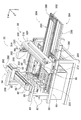
- FIG. 1 shows a component mounter 10.
- the component mounter 10 is a device for performing a component mounting operation on the circuit substrate 12.
- the component mounting machine 10 includes an apparatus main body 20, a base material conveyance holding device 22, a component mounting device 24, imaging devices 26 and 28, a component supply device 30, and a bulk component supply device 32.
- the circuit substrate 12 includes a circuit board, a three-dimensional structure substrate, and the like, and the circuit board includes a printed wiring board and a printed circuit board.
- the apparatus main body 20 includes a frame portion 40 and a beam portion 42 that is overlaid on the frame portion 40.
- the substrate conveyance holding device 22 is disposed in the center of the frame portion 40 in the front-rear direction, and includes a conveyance device 50 and a clamp device 52.
- the conveyance device 50 is a device that conveys the circuit substrate 12
- the clamp device 52 is a device that holds the circuit substrate 12.
- the base material transport and holding device 22 transports the circuit base material 12 and holds the circuit base material 12 fixedly at a predetermined position.
- the conveyance direction of the circuit substrate 12 is referred to as an X direction
- a horizontal direction perpendicular to the direction is referred to as a Y direction
- a vertical direction is referred to as a Z direction. That is, the width direction of the component mounting machine 10 is the X direction, and the front-rear direction is the Y direction.
- the component mounting device 24 is disposed in the beam portion 42 and includes two work heads 60 and 62 and a work head moving device 64.
- Each work head 60, 62 has a component holder 66 (see FIG. 2) 66 such as a chuck and a suction nozzle, and holds the component by the component holder 66.
- the work head moving device 64 includes an X direction moving device 68, a Y direction moving device 70, and a Z direction moving device 72. Then, the two working heads 60 and 62 are integrally moved to arbitrary positions on the frame portion 40 by the X-direction moving device 68 and the Y-direction moving device 70. Further, as shown in FIG.
- each work head 60, 62 is detachably attached to the sliders 74, 76, and the Z-direction moving device 72 individually moves the sliders 74, 76 in the vertical direction. That is, the work heads 60 and 62 are individually moved in the vertical direction by the Z-direction moving device 72.
- the imaging device 26 is attached to the slider 74 in a state of facing downward, and is moved together with the work head 60 in the X direction, the Y direction, and the Z direction. Thereby, the imaging device 26 images an arbitrary position on the frame unit 40. As shown in FIG. 1, the imaging device 28 is disposed between the base material conveyance holding device 22 and the component supply device 30 on the frame portion 40 so as to face upward. Thereby, the imaging device 28 images the components held by the component holder 66 of the work heads 60 and 62.
- the component supply device 30 is disposed at one end of the frame portion 40 in the front-rear direction.
- the component supply device 30 includes a tray-type component supply device 78 and a feeder-type component supply device (not shown).
- the tray-type component supply device 78 is a device that supplies components placed on the tray.
- the feeder-type component supply device is a device that supplies components using a tape feeder (not shown) and a stick feeder (not shown).
- the bulk component supply device 32 is disposed at the other end portion of the frame portion 40 in the front-rear direction.
- the separated component supply device 32 is a device for aligning a plurality of components scattered in a separated state and supplying the components in an aligned state. That is, it is an apparatus that aligns a plurality of components in an arbitrary posture into a predetermined posture and supplies the components in a predetermined posture.
- the structure of the component supply apparatus 32 is demonstrated in detail.
- examples of the components supplied by the component supply device 30 and the bulk component supply device 32 include electronic circuit components, solar cell components, and power module components.
- Electronic circuit components include components having leads and components not having leads.
- the bulk component supply device 32 includes a main body 80, a component supply unit 82, an imaging device 84, and a component delivery device 86.
- the component supply unit 82 includes a component supplier 88, a component scattered state realization device 90, and a component return device 92, and the component supplier 88, the component scattered state realization device 90, and the component return device 92. Are integrally configured.
- the component supply unit 82 is detachably assembled to the base 96 of the main body 80. In the bulk component supply device 32, five component supply units 82 are arranged in a line in the X direction.
- the component supplier 88 includes a component container 100, a housing 102, and a grip 104 as shown in FIG.
- the component container 100 has a generally rectangular parallelepiped shape, and an upper surface and a front surface are open.
- the bottom surface of the component container 100 is an inclined surface 116, which is inclined toward the front surface where the component container 100 is opened.
- the housing 102 has a pair of side walls 120, and the component container 100 is slidably held between the pair of side walls 120.
- An inclined plate 152 is fixedly disposed between the pair of side walls 120 so as to be positioned in front of the lower end portion of the front surface of the component container 100.
- the inclined plate 152 is inclined so as to descend toward the front.
- the grip 104 is disposed at an end portion on the rear side of the housing 102 and includes a fixed gripping member 170 and a movable gripping member 172.
- the movable gripping member 172 can be moved toward and away from the fixed gripping member 170.
- the movable gripping member 172 is connected to the rear surface of the component container 100 by a connecting arm (not shown). As a result, when the grip 104 is gripped, the movable gripping member 172 approaches and separates from the fixed gripping member 170, and the component container 100 swings between the pair of side walls 120.
- the component supplier 88 is disposed between a pair of side frame portions 190 assembled to the base 96, and can be attached to and detached from the base 96.
- a lock mechanism (not shown) is provided at the lower end of the movable grip member 172 of the grip 104, and the lock mechanism is released when the grip 104 is gripped. That is, when the operator holds the grip 104 of the component supplier 88 and lifts the component supplier 88, the component supplier 88 is removed from between the pair of side frame portions 190.
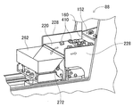
- the component scattered state realization device 90 includes a component support member 220, a component support member moving device 222, and a feeder vibration device 224.
- the component support member 220 has a generally longitudinal plate shape and is disposed so as to extend forward from below the inclined plate 152 of the component feeder 88.
- Side wall portions 228 are formed on both side edges in the longitudinal direction of the component support member 220.
- the component support member moving device 222 is a device that moves the component support member 220 in the front-rear direction by driving an electromagnetic motor (not shown). As a result, the component support member 220 moves in the front-rear direction slightly below the lower end of the inclined plate 152 of the component supplier 88 with the upper surface of the component support member 220 being horizontal.
- the feeder vibration device 224 includes a cam member 240, a cam follower 242, and a stopper 244.
- the cam member 240 has a plate shape and is fixed to the outer side surface of the side wall portion 228 so as to extend in the front-rear direction.
- a plurality of teeth 245 are formed at equal intervals in the front-rear direction.
- the cam follower 242 includes a lever 252 and a roller 254.
- the lever 252 is disposed at the lower end portion of the side wall 120 of the component supplier 88 and can swing around the upper end portion.
- the roller 254 is rotatably held at the lower end portion of the lever 252.
- the lever 252 is biased in the forward direction by the elastic force of a coil spring (not shown).
- the stopper 244 is provided in a protruding shape on the side wall 120, and a lever 252 biased by the elastic force of the coil spring is in contact with the stopper 244.
- the component return device 92 includes a container lifting device 260 and a component collection container 262 as shown in FIG.
- the container elevating device 260 includes an air cylinder 266 and an elevating member 268, and the elevating member 268 moves up and down by the operation of the air cylinder 266.
- the air cylinder 266 is fixed to the front end of the component support member 220. Thus, the air cylinder 266 moves in the front-rear direction together with the component support member 220 by the operation of the component support member moving device 222.
- the component collection container 262 is disposed on the upper surface of the elevating member 268 and moves up and down by the operation of the air cylinder 266.
- the component collection container 262 has a box shape with an open top surface, and is rotatably held on the top surface of the elevating member 268.
- a protruding pin 272 is disposed at the rear end of the component collection container 262.
- the protruding pin 272 protrudes outward on the side of the component collection container 262.
- an engagement block 274 is fixed inside the upper end portion on the front side of the side frame portion 190. As shown in FIG. 5, when the component collection container 262 is raised to the rising end position by the operation of the air cylinder 266, the protruding pin 272 is engaged with the engagement block 274. Thereby, the parts collection container 262 rotates.
- the imaging device 84 includes a camera 290 and a camera moving device 292.
- the camera moving device 292 includes a guide rail 296 and a slider 298.
- the guide rail 296 is fixed to the main body 80 so as to extend in the width direction of the loose component supply device 32 above the component supplier 88.
- the slider 298 is slidably attached to the guide rail 296, and slides to an arbitrary position by the operation of an electromagnetic motor (not shown).
- the camera 290 is attached to the slider 298 so as to face downward.
- the component delivery device 86 includes a component holding head moving device 300, a component holding head 302, and two shuttle devices 304, as shown in FIG.
- the component holding head moving device 300 includes an X direction moving device 310, a Y direction moving device 312, and a Z direction moving device 314.
- the Y-direction moving device 312 has a Y slider 316 disposed above the component supply unit 82 so as to extend in the X direction.
- the Y slider 316 is driven by an electromagnetic motor (not shown). Move to any position in the direction.
- the X-direction moving device 310 has an X-slider 320 disposed on the side surface of the Y-slider 316, and the X-slider 320 moves to an arbitrary position in the X-direction by driving an electromagnetic motor (not shown). .
- the Z-direction moving device 314 has a Z-slider 322 disposed on the side surface of the X-slider 320, and the Z-slider 322 moves to an arbitrary position in the Z-direction by driving an electromagnetic motor (not shown). .
- the component holding head 302 includes a head main body 330, a suction nozzle 332, a nozzle turning device 334, and a nozzle rotating device 335.
- the head body 330 is formed integrally with the Z slider 322.
- the suction nozzle 332 is for sucking and holding components by negative pressure, and is attached to the lower end of the nozzle holder 340.
- the nozzle holder 340 can be bent at the support shaft 344, and the nozzle holder 340 is bent 90 degrees upward by the operation of the nozzle turning device 334.
- the suction nozzle 332 attached to the lower end of the nozzle holder 340 turns 90 degrees and is located at the turning position. That is, the suction nozzle 332 turns between the non-turning position and the turning position by the operation of the nozzle turning device 334.
- the nozzle rotating device 335 rotates the suction nozzle 332 around its axis.
- each of the two shuttle devices 304 includes a component carrier 388 and a component carrier moving device 390, and is fixed to the main body 80 side by side in front of the component supply unit 82. Yes.
- Five component receiving members 392 are mounted on the component carrier 388 in a row in the horizontal direction, and the components are placed on each component receiving member 392.
- the component supplied by the bulk component supply device 32 is an electronic circuit component (hereinafter, may be abbreviated as “lead component”) 410 having a lead.
- the block-shaped component main body 412 and a plurality of leads 414 protruding from the bottom surface 413 of the component main body 412 are configured.
- the lead component 410 is a so-called SIP (Single Inline Package) in which a plurality of leads 414 are arranged in a row on one side of the component body 412, and in FIG. 7, the lead component 410 is a plurality of leads. It is shown from the viewpoint from the direction in which 414 is arranged. Therefore, only one lead 414 is shown in the lead component 410 of FIG.
- the component receiving member 392 is formed with a component receiving recess 416.
- the component receiving recess 416 is a stepped recess, and includes a main body receiving recess 418 that opens to the top surface of the component receiving member 392 and a lead receiving recess 420 that opens to the bottom surface of the main body receiving recess 418.
- the lead component 410 is inserted into the component receiving recess 416 with the lead 414 facing downward.
- the lead 414 is inserted into the lead receiving recess 420 and the lead component 410 is placed inside the component receiving recess 416 with the component main body 412 inserted into the main body receiving recess 418.
- a side wall 422 is formed on the component receiving member 392 in a state of being slightly separated from the edge of the main body receiving recess 418.
- the side wall portion 422 is generally erected in the vertical direction, and a step portion 424 is formed between the side wall portion 422 and the main body portion receiving recess 418.
- a taper surface 426 is formed at the edge of the lead receiving recess 420 on the side of the stepped portion 424 so as to be continuous with the main body receiving recess 418, and this tapered surface 426 is formed on the bottom surface of the lead receiving recess 420. It is inclined towards.
- the side wall portion 422, the stepped portion 424, and the tapered surface 426 are used when the lead component 410 is placed inside the component receiving recess 416, which will be described in detail later.
- the component carrier moving device 390 is a plate-like longitudinal member, and is disposed on the front side of the component supply unit 82 so as to extend in the front-rear direction.
- a component carrier 388 is disposed on the upper surface of the component carrier moving device 390 so as to be slidable in the front-rear direction, and slides to an arbitrary position in the front-rear direction by driving an electromagnetic motor (not shown).
- the component carrier 388 slides in a direction approaching the component supply unit 82
- the component carrier 388 slides to a component receiving position located within the movement range of the component holding head 302 by the component holding head moving device 300.
- the component carrier 388 slides in the direction away from the component supply unit 82
- the component carrier 388 slides to the component supply position located within the movement range of the work heads 60 and 62 by the work head moving device 64.
- the component mounting operation is performed on the circuit substrate 12 held by the substrate conveyance holding device 22 with the above-described configuration. Specifically, the circuit substrate 12 is transported to the work position, and is fixedly held by the clamp device 52 at that position. Next, the imaging device 26 moves above the circuit substrate 12 and images the circuit substrate 12. Thereby, the information regarding the error of the holding position of the circuit base material 12 is obtained.
- the component supply device 30 or the bulk component supply device 32 supplies components at a predetermined supply position. It should be noted that the supply of components by the bulk component supply device 32 will be described in detail later. Then, one of the work heads 60 and 62 moves above the component supply position, and the component holder 66 holds the component.
- the work heads 60 and 62 holding the components move above the imaging device 28, and the components held by the component holder 66 are imaged by the imaging device 28. As a result, information on the error of the component holding position can be obtained. Then, the work heads 60 and 62 holding the components move above the circuit substrate 12 and correct the held components for errors in the holding position of the circuit substrate 12, errors in the holding position of the components, and the like. And mounted on the circuit substrate 12.
- the lead component 410 thrown from the opening on the upper surface of the component container 100 falls on the inclined surface 116 of the component container 100 and spreads on the inclined surface 116. At this time, when the lead component 410 that has fallen on the inclined surface 116 rolls over the inclined plate 152, the lead component 410 is accommodated in the component collection container 262 located in front of the component supplier 88.
- the component support member 220 is moved from the lower part of the component feeder 88 to the front by the operation of the component support member moving device 222.
- the cam member 240 reaches the cam follower 242
- the roller 254 of the cam follower 242 gets over the teeth 245 of the cam member 240 as shown in FIG.
- the lever 252 of the cam follower 242 is biased in the forward direction by the elastic force of the coil spring, and the forward bias of the lever 252 is restricted by the stopper 244. For this reason, when the component support member 220 moves forward, the roller 254 and the teeth 245 are maintained in mesh with each other, the lever 252 does not rotate forward, and the roller 254 has the teeth 245. Get over.
- the component feeder 88 moves up and down as the roller 254 gets over the teeth 245. That is, in a state where the roller 254 is engaged with the teeth 245, the component support member 220 moves forward, so that the roller 254 gets over the plurality of teeth 245, and the component feeder 88 continuously vibrates in the vertical direction. .
- the lead component 410 spreading on the inclined surface 116 of the component container 100 moves forward due to the vibration of the component feeder 88 and the inclination of the inclined surface 116, and the upper surface of the component support member 220 via the inclined plate 152. To be discharged. At this time, the lead part 410 is prevented from dropping from the component support member 220 by the side wall portion 228 of the component support member 220. The lead parts 410 are scattered on the upper surface of the part support member 220 as the part support member 220 moves forward.
- the camera 290 of the imaging device 84 is moved above the component support member 220 in which the lead component 410 is scattered by the operation of the camera moving device 292.
- the part 410 is imaged.
- a lead component to be picked up (hereinafter sometimes abbreviated as “pickup target component”) is held by the suction nozzle 332 of the component holding head 302.
- the position of the pickup target component and the posture of the pickup target component are calculated based on the imaging data of the camera 290.
- the operation of the component holding head moving device 300 is controlled based on the calculated position of the pickup target component and the posture of the pickup target component.
- the component holding head 302 moves above the pickup target component, and the pickup target component is sucked and held by the suction nozzle 332.
- the suction nozzle 332 is located at the non-turning position.
- the component holding head 302 is moved above the component carrier 388.
- the component carrier 388 is moved to receive the component by the operation of the component carrier moving device 390. Moved to position.
- the suction nozzle 332 is pivoted to the pivot position. The suction nozzle 332 is rotated by the operation of the nozzle rotating device 335 so that the lead 414 of the lead component 410 held by the suction nozzle 332 in the turning position faces downward in the vertical direction.
- the lead component 410 with the lead 414 facing downward in the vertical direction is inserted into the component receiving member 392.
- the lead component 410 is placed on the component receiving member 392 with the lead 414 facing downward in the vertical direction.
- only the lead components 410 scattered in a predetermined posture on the component support member 220 are placed on the component receiving member 392 according to the above-described procedure.
- the lead parts 410 scattered on the part support member 220 include lead parts (hereinafter, referred to as bottom parts 413 from which the leads 414 of the part main body 412 protrude upward).
- 410a and a lead component with the side surface 430 of the component main body 412 facing upward (hereinafter may be described as a “90-degree rotated state component”).
- 410b a lead component with the side surface 430 of the component main body 412 facing upward.
- the lead component 410 is positioned above the component support member 220. Although it may be scattered, it is omitted here.
- the suction nozzle 332 In the 90-degree rotated state component 410b scattered on the component support member 220, the side surface 430 of the component main body 412 faces upward, so that the suction nozzle 332 is rotated by 90 ° on the side surface 430 of the component main body 412. 410b is sucked and held.
- the suction nozzle 332 is located at the non-turning position, and the suction nozzle 332 is operated by the operation of the nozzle rotating device 335 in order to adjust the direction of the lead 414 of the held lead component 410. , Rotated.
- the suction nozzle 332 is turned to the turning position by the operation of the nozzle turning device 334, so that the lead 414 of the held lead component 410 faces downward in the vertical direction.
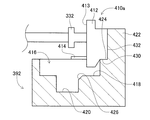
- the suction nozzle 332 moves above the component receiving member 392 and the lead component 410 is detached, the lead component 410 held by the suction nozzle 332 becomes a component of the component receiving member 392 as shown in FIG. It is placed in the receiving recess 416.
- the bottom surface 413 of the component main body 412 faces upward as shown in FIG.
- the 180-degree rotated state component 410a is sucked and held.
- the suction nozzle 332 is located at the non-turning position, and in this state, the lead 414 of the 180-degree rotation state component 410a held by the suction nozzle 332 faces upward.
- the lead 414 is generally oriented in the horizontal direction as shown in FIG.
- the 180-degree rotated state component 410 a is placed in the component receiving recess 416 by using the side wall portion 422, the stepped portion 424, and the tapered surface 426 of the component receiving member 392.
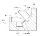
- the suction nozzle 332 positioned at the non-turning position holds the 180-degree rotated state component 410 a on the component support member 220, and the suction nozzle 332 is turned to the turning position by the operation of the nozzle turning device 334.
- the suction nozzle 332 is arranged so that the lead 414 of the 180-degree rotation state component 410a held by the suction nozzle 332 in the swivel position is located below the suction nozzle 332 as shown in FIG. It is rotated by the operation of.
- the suction nozzle 332 swung to the swivel position is moved in the left-right direction above the component receiving member 392, so that the top surface opposite to the bottom surface 413 of the 180-degree rotated state component 410a held by the suction nozzle 332 is obtained.
- 432 contacts the side wall 422 of the component receiving member 392.
- a part of the side surface 430 of the 180-degree rotated state component 410 a comes into contact with the step portion 424 of the component receiving member 392.
- the suction nozzle 332 disengages the 180-degree rotation state component 410a, so that the 180-degree rotation state component 410a is caused by its own weight around the side surface 430 that is in contact with the corner on the component receiving recess 416 side of the step portion 424. Inclined toward the component receiving recess 416. At this time, as shown in FIG. 11, the lead 414 of the 180-degree rotated state component 410 a contacts the tapered surface 426 of the component receiving member 392. The 180-degree rotation state component 410a further falls while rotating due to its own weight. At this time, the lead 414 of the 180-degree rotation state component 410 a slides down along the tapered surface 426.
- the lead 414 of the 180 ° rotated state component 410a is accommodated in the lead receiving recess 420 of the component receiving recess 416 as shown in FIG. 7, and the component body 412 of the 180 ° rotated state component 410a is accommodated in the component receiving recess. 416 is accommodated in the body receiving recess 418.
- the 180-degree rotated state component 410 a is placed in the component receiving recess 416 by being rotated 90 degrees using the side wall portion 422, the stepped portion 424, and the tapered surface 426 of the component receiving member 392. .
- the 90 ° rotation of the suction nozzle 332 by the nozzle turning device 334 and the 90 ° rotation of the 180 ° rotation state component 410a by the component receiving member 502 cause the 180 ° rotation state component 410a, that is, the component support member 220 to move.
- the lead component placed with the bottom surface 413 facing upward by 180 degrees the lead component can be accommodated in the component receiving recess 504 with the top surface 432 facing upward.
- the lead component carrier 388 a plurality of types of component receiving members corresponding to the shape of the lead component are prepared. Specifically, when the lead component 450 having the shape shown in FIG. 12 is a pickup target component, the lead component 450 is placed on a component receiving member 452 having a shape corresponding to the lead component 450. Specifically, the lead component 450 includes a component main body 454 and a lead 456, and an inclined surface 462 that is inclined toward the bottom surface 460 is formed at the center of the side surface 458 of the component main body 454.
- the component receiving member 452 is formed with a component receiving recess 466.
- the component receiving recess 466 is a stepped recess having a main body receiving recess 468 that opens to the upper surface of the component receiving member 452 and a lead receiving recess 470 that opens to the bottom surface of the main body receiving recess 468.
- one side surface 472 that defines the main body receiving recess 468 has a length that is approximately twice the depth of the main body receiving recess 468. That is, the one side surface 472 projects upward from the other side surface that defines the main body portion receiving recess 468.
- a tapered surface 476 is formed on the edge of the lead receiving recess 470 on the side surface 472 side so as to be continuous with the main body receiving recess 468, and this tapered surface 476 is directed toward the bottom surface of the lead receiving recess 470. Inclined.
- the lead component 450 scattered on the component support member 220 with the bottom surface 460 facing upward is placed on the component receiving member 452 having such a shape, similarly to the 180-degree rotated component 410a.
- the lead component 450 on the component support member 220 is held by the suction nozzle 332 positioned at the non-turning position, and the suction nozzle 332 is turned to the turning position by the operation of the nozzle turning device 334.
- the suction nozzle 332 is operated by the operation of the nozzle rotation device 335 so that the lead 456 of the lead component 450 held by the suction nozzle 332 in the swivel position is positioned below the suction nozzle 332 as shown in FIG. , Rotated.
- the suction nozzle 332 that has swung to the swivel position is moved in the left-right direction above the component receiving member 452, so that a portion that is continuous with the inclined surface 462 of the side surface 458 of the lead component 450 held by the suction nozzle 332. Is in contact with the side surface 472 of the component receiving member 452.
- the lead component 450 is inclined toward the component receiving recess 466 by its own weight, with the portion continuing to the inclined surface 462 of the side surface 458 as the center.
- the lead 456 of the lead component 450 contacts the tapered surface 476 of the component receiving member 452 as shown in FIG.
- the lead component 450 further falls while rotating due to its own weight.
- the lead 456 of the lead component 450 slides down along the tapered surface 476.
- the lead 456 of the lead component 450 is accommodated in the lead receiving recess 470 of the component receiving recess 466 as shown in FIG.
- the component main body 454 of the lead component 450 is received by the main body receiving recess of the component receiving recess 466. Housed in 468.
- the component receiving members 392 and 452 corresponding to the shapes of the lead components 410 and 450 are prepared, and the lead components 410 and 450 include the component receiving members 392 and 452 corresponding to their own shapes. Placed on.
- the component carrier 388 moves to the component supply position by the operation of the component carrier moving device 390. Since the component carrier 388 moved to the component supply position is located in the movement range of the work heads 60 and 62, the lead component 410 is supplied at this position in the loose component supply device 32. Thus, in the loose component supply device 32, the lead component 410 is supplied in a state where the lead 414 faces downward and the surface facing the surface to which the lead 414 is connected faces upward. Therefore, the component holder 66 of the work heads 60 and 62 can appropriately hold the lead component 410.
- the lead components 410 scattered on the component support member 220 can be collected. Specifically, the component support member 220 is moved downward of the component feeder 88 by the operation of the component support member moving device 222. At this time, as shown in FIG. 15, the lead component 410 on the component support member 220 is blocked by the inclined plate 152 of the component supplier 88, and the lead component 410 on the component support member 220 is inserted into the component collection container 262. It is scraped off inside.
- the parts collection container 262 is raised by the operation of the container lifting device 260.
- the protruding pin 272 disposed in the component collection container 262 engages with an engagement block 274 disposed inside the side frame portion 190.
- the component collection container 262 rotates, and the lead component 410 in the component collection container 262 is returned to the inside of the component container 100.
- the 180-degree rotation state component 410a and the 90-degree rotation state component 410b scattered on the component support member 220 are picked up by the suction nozzle 332. For this reason, the number of lead components 410 returned to the component container 100 can be reduced.
- the lock of the component supplier 88 is released, and when the component supplier 88 is lifted, the component supplier 88 is paired. It is removed from between the side frame parts 190 of. As a result, the lead component 410 is recovered from the component supplier 88 outside the bulk component supply device 32.
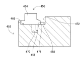
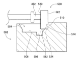
- this invention is not limited to the said Example, It is possible to implement in the various aspect which gave various change and improvement based on the knowledge of those skilled in the art. Specifically, for example, in the above embodiment, the lead components 410 and 450 having the leads 414 and 456 are placed on the component receiving members 392 and 452, but the electronic components having no leads are replaced with the component receiving members. It is also possible to mount it. Specifically, for example, when the electronic component 500 having the shape shown in FIG. 16 is a pickup target component, the electronic component 500 is placed on a component receiving member 502 having a shape corresponding to the electronic component 500. A component receiving recess 504 is formed in the component receiving member 502.
- the component receiving recess 504 is a stepped recess, and includes a main body receiving recess 506 that opens to the upper surface of the component receiving member 502 and a recess 508 that opens to the bottom surface of the main body receiving recess 506.
- one side surface 510 that defines the main body receiving recess 506 is longer than the depth dimension of the main body receiving recess 506. That is, the one side 510 projects upward from the other side defining the main body receiving recess 506.
- a tapered surface 512 is formed at the edge of the concave portion 508 on the side surface 510 side, and the tapered surface 512 is inclined toward the bottom surface of the concave portion 508. Further, a step surface 514 is formed between the tapered surface 512 and the side surface 510.
- the electronic component 500 scattered with the bottom surface 520 facing upward is placed on the component support member 220 on the component receiving member 502 having such a shape, similarly to the 180-degree rotated state component 410a.
- the electronic component 500 on the component support member 220 is held by the suction nozzle 332 located at the non-turning position, and the suction nozzle 332 is turned to the turning position by the operation of the nozzle turning device 334.
- the bottom surface 520 of the electronic component 500 held by the suction nozzle 332 is in a posture extending in the vertical direction.
- the suction nozzle 332 swung to the swivel position is moved in the left-right direction above the component receiving member 502, so that the upper surface 522 opposite to the bottom surface 520 of the electronic component 500 held by the suction nozzle 332 is It contacts the side surface 510 of the component receiving member 502. At this time, the side surface 524 of the electronic component 500 contacts the stepped surface 514 of the component receiving member 502.
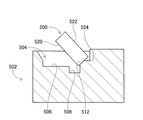
- the suction nozzle 332 separates the electronic component 500
- the electronic component 500 moves toward the component receiving recess 504 by its own weight, centering on the side surface 524 that contacts the corner between the tapered surface 512 and the step surface 514. Tilt.
- the side surface 524 of the electronic component 500 contacts the tapered surface 512 of the component receiving member 502 as shown in FIG.
- the electronic component 500 further falls while rotating due to its own weight.
- the side surface 524 of the electronic component 500 slides down along the tapered surface 512, and the corner portion of the side surface 524 of the electronic component 500 enters the recess 508 of the component receiving recess 504.
- the electronic component 500 is accommodated in the main body receiving recess 506 of the component receiving recess 504 as shown in FIG.
- the component support member 220 is rotated by the 90-degree rotation of the suction nozzle 332 by the nozzle rotation device 334 and the rotation of the electronic component 500 by the component receiving member 502.
- the electronic component 500 in the state of being placed on the component receiving portion 504 can be accommodated in the component receiving recess 504 in a state rotated 180 degrees, that is, in a state where the electronic component 500 is turned upside down.
- the present invention is applied to the component delivery device 86 having a structure in which the suction nozzle 332 is rotated 90 degrees by the nozzle turning device 334.
- the present invention is also applied to an apparatus in which the suction nozzle is not turned. It is possible to apply. Specifically, for example, in an apparatus having a structure in which the suction nozzle does not rotate, when the 90-degree rotation state components 410b (see FIG. 9) are scattered on the component support member 220, the suction nozzle 332 is a 90-degree rotation state component. The side surface 430 of 410b is sucked and held. In this state, the suction nozzle 332 holding the 90-degree rotated component 410b is moved above the component receiving member 392.
- the present invention can be applied to an apparatus having a structure in which the suction nozzle does not rotate.
- the lead component 410 is rotated 90 degrees in the component receiving member 392 using the tapered surface 476, but instead of the tapered surface, using a convex portion, a concave portion, a stepped portion, etc.
- the lead component 410 can be rotated 90 degrees on the component receiving member 392.
Landscapes
- Engineering & Computer Science (AREA)
- Manufacturing & Machinery (AREA)
- Microelectronics & Electronic Packaging (AREA)
- Mechanical Engineering (AREA)
- Supply And Installment Of Electrical Components (AREA)
Abstract
Description
図1に、部品実装機10を示す。部品実装機10は、回路基材12に対する部品の実装作業を実行するための装置である。部品実装機10は、装置本体20、基材搬送保持装置22、部品装着装置24、撮像装置26,28、部品供給装置30、ばら部品供給装置32を備えている。なお、回路基材12として、回路基板、三次元構造の基材等が挙げられ、回路基板として、プリント配線板、プリント回路板等が挙げられる。
部品供給ユニット82は、部品供給器88と部品散在状態実現装置90と部品戻し装置92とを含み、それら部品供給器88と部品散在状態実現装置90と部品戻し装置92とが一体的に構成されたものである。部品供給ユニット82は、本体80のベース96に着脱可能に組み付けられており、ばら部品供給装置32では、5台の部品供給ユニット82が、X方向に1列に並んで配設されている。
部品供給器88は、図4に示すように、部品収納器100とハウジング102とグリップ104とを含む。部品収納器100は、概して直方体形状をなし、上面と前面とが開口している。その部品収納器100の底面は、傾斜面116となっており、部品収納器100の開口する前面に向かって傾斜している。
部品散在状態実現装置90は、部品支持部材220と部品支持部材移動装置222と供給器振動装置224とを含む。部品支持部材220は、概して長手形状の板形状をなし、部品供給器88の傾斜板152の下方から前方に延び出すように、配設されている。また、部品支持部材220の長手方向の両側縁には、側壁部228が形成されている。
部品戻し装置92は、図5に示すように、容器昇降装置260と部品回収容器262とを含む。容器昇降装置260は、エアシリンダ266と昇降部材268とを含み、昇降部材268は、エアシリンダ266の作動により、昇降する。また、エアシリンダ266は、部品支持部材220の前方側の端部に固定されている。これにより、エアシリンダ266は、部品支持部材移動装置222の作動により、部品支持部材220と共に前後方向に移動する。
撮像装置84は、図3に示すように、カメラ290とカメラ移動装置292とを含む。カメラ移動装置292は、ガイドレール296とスライダ298とを含む。ガイドレール296は、部品供給器88の上方において、ばら部品供給装置32の幅方向に延びるように、本体80に固定されている。スライダ298は、ガイドレール296にスライド可能に取り付けられており、電磁モータ(図示省略)の作動により、任意の位置にスライドする。また、カメラ290は、下方を向いた状態でスライダ298に装着されている。
部品引渡し装置86は、図3に示すように、部品保持ヘッド移動装置300と部品保持ヘッド302と2台のシャトル装置304とを含む。
部品実装機10は、上述した構成によって、基材搬送保持装置22に保持された回路基材12に対して部品の装着作業が行われる。具体的には、回路基材12が、作業位置まで搬送され、その位置において、クランプ装置52によって固定的に保持される。次に、撮像装置26が、回路基材12の上方に移動し、回路基材12を撮像する。これにより、回路基材12の保持位置の誤差に関する情報が得られる。また、部品供給装置30若しくは、ばら部品供給装置32は、所定の供給位置において、部品を供給する。なお、ばら部品供給装置32による部品の供給に関しては、後で詳しく説明する。そして、作業ヘッド60,62の何れかが、部品の供給位置の上方に移動し、部品保持具66によって部品を保持する。続いて、部品を保持した作業ヘッド60,62が、撮像装置28の上方に移動し、撮像装置28によって、部品保持具66に保持された部品が撮像される。これにより、部品の保持位置の誤差に関する情報が得られる。そして、部品を保持した作業ヘッド60,62が、回路基材12の上方に移動し、保持している部品を、回路基材12の保持位置の誤差,部品の保持位置の誤差等を補正し、回路基材12上に装着する。
(a)ばら部品供給装置によるリード部品の供給
ばら部品供給装置32では、リード部品410が、作業者によって部品供給器88の部品収納器100に投入され、その投入されたリード部品410が、部品供給ユニット82,部品引渡し装置86の作動により、部品キャリヤ388の部品受け部材392に載置された状態で供給される。詳しくは、作業者は、部品供給器88の部品収納器100の上面の開口から、リード部品410を投入する。この際、部品支持部材220は、部品支持部材移動装置222の作動により、部品供給器88の下方に移動しており、部品供給器88の前方には、部品回収容器262が位置している。
また、ばら部品供給装置32では、部品支持部材220の上に散在するリード部品410を回収することが可能である。詳しくは、部品支持部材220が、部品支持部材移動装置222の作動により、部品供給器88の下方に向かって移動させられる。この際、図15に示すように、部品支持部材220上のリード部品410は、部品供給器88の傾斜板152によって堰き止められ、部品支持部材220上のリード部品410が、部品回収容器262の内部に掻き落とされる。
Claims (3)
- 収納対象の部品に応じた形状の収納凹部と、
部品保持具により保持された部品が左右方向に移動された際に当接する当接部と
を備え、
部品保持具により保持された部品が前記当接部に当接した状態で前記部品保持具による部品の保持が解除された場合に、その部品が、前記当接部から前記収納凹部の底面に至る面の少なくとも一部に沿って落下することで、自重により90度回転して前記収納凹部に収納されることを特徴とする部品収納部材。 - 前記部品収納部材が、
前記当接部から前記収納凹部の底面に至る面の少なくとも一部に形成されるとともに、前記収納凹部に向かって傾斜するテーパ面を備え、
当該部品収納部材が、
部品保持具により保持された部品が前記当接部に当接した状態で前記部品保持具による部品の保持が解除された場合に、その部品が前記テーパ面の一部に沿って落下することで、自重により90度回転して前記収納凹部に収納されることを特徴とする請求項1に記載の部品収納部材。 - 収納対象の部品に応じた形状の収納凹部を備える部品収納部材への部品の収納方法であって、
当該収納方法が、
載置台に所定の面を接触させた状態で載置された部品を、部品保持具により保持する保持工程と、
前記部品保持具に保持された部品を、前記部品保持具の旋回機構により上下方向に90度旋回させる旋回工程と、
前記部品保持具に保持された部品の前記所定の面を、前記部品収納部材の収納凹部の底面に垂直な当接部に当接させる当接工程と、
前記所定の面を前記当接部に当接させた状態で前記部品保持具による部品の保持が解除され、その部品が前記当接部から前記収納凹部の底面に至る面の少なくとも一部に沿って落下することで、その部品を自重により90度回転させ、前記所定の面を上に向けた状態で前記収納凹部に収納させる収納工程と
を含むことを特徴とする収納方法。
Priority Applications (5)
| Application Number | Priority Date | Filing Date | Title |
|---|---|---|---|
| US15/533,055 US10233030B2 (en) | 2014-12-11 | 2014-12-11 | Component storage member and storage method |
| EP14907762.0A EP3232755B1 (en) | 2014-12-11 | 2014-12-11 | System for storing a component, and component housing method |
| CN201480083851.5A CN107006142B (zh) | 2014-12-11 | 2014-12-11 | 作业机及收纳方法 |
| JP2016563344A JP6522653B2 (ja) | 2014-12-11 | 2014-12-11 | 作業機、および収納方法 |
| PCT/JP2014/082787 WO2016092658A1 (ja) | 2014-12-11 | 2014-12-11 | 部品収納部材、および収納方法 |
Applications Claiming Priority (1)
| Application Number | Priority Date | Filing Date | Title |
|---|---|---|---|
| PCT/JP2014/082787 WO2016092658A1 (ja) | 2014-12-11 | 2014-12-11 | 部品収納部材、および収納方法 |
Publications (1)
| Publication Number | Publication Date |
|---|---|
| WO2016092658A1 true WO2016092658A1 (ja) | 2016-06-16 |
Family
ID=56106908
Family Applications (1)
| Application Number | Title | Priority Date | Filing Date |
|---|---|---|---|
| PCT/JP2014/082787 Ceased WO2016092658A1 (ja) | 2014-12-11 | 2014-12-11 | 部品収納部材、および収納方法 |
Country Status (5)
| Country | Link |
|---|---|
| US (1) | US10233030B2 (ja) |
| EP (1) | EP3232755B1 (ja) |
| JP (1) | JP6522653B2 (ja) |
| CN (1) | CN107006142B (ja) |
| WO (1) | WO2016092658A1 (ja) |
Cited By (4)
| Publication number | Priority date | Publication date | Assignee | Title |
|---|---|---|---|---|
| JPWO2019058499A1 (ja) * | 2017-09-22 | 2019-12-19 | 株式会社Fuji | 部品供給装置 |
| JP2019220520A (ja) * | 2018-06-18 | 2019-12-26 | 株式会社Fuji | 吸着ノズルの回収装置と吸着ノズルの回収方法 |
| JP7503746B2 (ja) | 2020-09-02 | 2024-06-21 | パナソニックIpマネジメント株式会社 | 部品実装装置および方法 |
| JP7534606B2 (ja) | 2020-06-19 | 2024-08-15 | 株式会社デンソーウェーブ | 部品組み付け装置 |
Families Citing this family (4)
| Publication number | Priority date | Publication date | Assignee | Title |
|---|---|---|---|---|
| US10292319B2 (en) * | 2014-04-22 | 2019-05-14 | Fuji Corporation | Load measurement method and collection method |
| WO2016135909A1 (ja) * | 2015-02-26 | 2016-09-01 | 富士機械製造株式会社 | 部品供給装置、および装着機 |
| EP3675619B1 (en) | 2015-03-03 | 2022-06-08 | FUJI Corporation | Component supply device and components supply method |
| JP6717275B2 (ja) * | 2017-09-19 | 2020-07-01 | 井関農機株式会社 | 作業車両 |
Citations (5)
| Publication number | Priority date | Publication date | Assignee | Title |
|---|---|---|---|---|
| JPH02180099A (ja) * | 1988-12-30 | 1990-07-12 | Matsushita Electron Corp | 半導体素子の位置決め搬送装置 |
| JPH04199797A (ja) * | 1990-11-29 | 1992-07-20 | Hitachi Telecom Technol Ltd | Ic等の部品供給方法及び部品供給装置 |
| JPH06115695A (ja) * | 1992-10-06 | 1994-04-26 | Daihatsu Motor Co Ltd | 薄形円筒状ワークの整列装置 |
| JP2001225941A (ja) * | 2000-02-10 | 2001-08-21 | Taiyo Yuden Co Ltd | 電子部品供給装置 |
| JP2012222245A (ja) * | 2011-04-12 | 2012-11-12 | Juki Corp | 部品供給装置及び実装装置 |
Family Cites Families (12)
| Publication number | Priority date | Publication date | Assignee | Title |
|---|---|---|---|---|
| JPS5670212A (en) | 1979-11-09 | 1981-06-12 | Hitachi Ltd | Method of arranging cylindrical parts |
| JPS5678387U (ja) | 1979-11-12 | 1981-06-25 | ||
| US4733462A (en) * | 1986-06-24 | 1988-03-29 | Sony Corporation | Apparatus for positioning circuit components at predetermined positions and method therefor |
| KR0169467B1 (ko) | 1988-10-14 | 1999-01-15 | 야마무라 가쯔미 | Ic패키지용 콘테이너 및 그 이송 방법 |
| JPH06127698A (ja) * | 1992-10-20 | 1994-05-10 | Omron Corp | 部品供給装置 |
| JPH0682897U (ja) * | 1993-03-19 | 1994-11-25 | 太陽誘電株式会社 | チップ状回路部品配置用テンプレート |
| JP3494828B2 (ja) * | 1996-11-18 | 2004-02-09 | 株式会社アドバンテスト | 水平搬送テストハンドラ |
| US6449531B1 (en) * | 2000-08-25 | 2002-09-10 | Advanced Micro Devices, Inc. | System for batching integrated circuits in trays |
| FR2944001A1 (fr) * | 2009-04-03 | 2010-10-08 | Ermap Vibrations | Installation de distribution de pieces. |
| JP2011014735A (ja) | 2009-07-02 | 2011-01-20 | Fujikura Ltd | チップを移動させる方法およびそのための治具 |
| JP6135598B2 (ja) * | 2013-08-20 | 2017-05-31 | 株式会社村田製作所 | チップの振込装置 |
| CN106458465B (zh) * | 2014-06-04 | 2019-03-19 | 株式会社村田制作所 | 搬运装置 |
-
2014
- 2014-12-11 CN CN201480083851.5A patent/CN107006142B/zh active Active
- 2014-12-11 WO PCT/JP2014/082787 patent/WO2016092658A1/ja not_active Ceased
- 2014-12-11 EP EP14907762.0A patent/EP3232755B1/en active Active
- 2014-12-11 JP JP2016563344A patent/JP6522653B2/ja active Active
- 2014-12-11 US US15/533,055 patent/US10233030B2/en active Active
Patent Citations (5)
| Publication number | Priority date | Publication date | Assignee | Title |
|---|---|---|---|---|
| JPH02180099A (ja) * | 1988-12-30 | 1990-07-12 | Matsushita Electron Corp | 半導体素子の位置決め搬送装置 |
| JPH04199797A (ja) * | 1990-11-29 | 1992-07-20 | Hitachi Telecom Technol Ltd | Ic等の部品供給方法及び部品供給装置 |
| JPH06115695A (ja) * | 1992-10-06 | 1994-04-26 | Daihatsu Motor Co Ltd | 薄形円筒状ワークの整列装置 |
| JP2001225941A (ja) * | 2000-02-10 | 2001-08-21 | Taiyo Yuden Co Ltd | 電子部品供給装置 |
| JP2012222245A (ja) * | 2011-04-12 | 2012-11-12 | Juki Corp | 部品供給装置及び実装装置 |
Cited By (6)
| Publication number | Priority date | Publication date | Assignee | Title |
|---|---|---|---|---|
| JPWO2019058499A1 (ja) * | 2017-09-22 | 2019-12-19 | 株式会社Fuji | 部品供給装置 |
| EP3687267A4 (en) * | 2017-09-22 | 2020-09-02 | Fuji Corporation | COMPONENT SUPPLY SYSTEM |
| JP2019220520A (ja) * | 2018-06-18 | 2019-12-26 | 株式会社Fuji | 吸着ノズルの回収装置と吸着ノズルの回収方法 |
| JP7111518B2 (ja) | 2018-06-18 | 2022-08-02 | 株式会社Fuji | 吸着ノズルの回収装置と吸着ノズルの回収方法 |
| JP7534606B2 (ja) | 2020-06-19 | 2024-08-15 | 株式会社デンソーウェーブ | 部品組み付け装置 |
| JP7503746B2 (ja) | 2020-09-02 | 2024-06-21 | パナソニックIpマネジメント株式会社 | 部品実装装置および方法 |
Also Published As
| Publication number | Publication date |
|---|---|
| CN107006142A (zh) | 2017-08-01 |
| US10233030B2 (en) | 2019-03-19 |
| EP3232755A4 (en) | 2018-03-21 |
| US20170341874A1 (en) | 2017-11-30 |
| EP3232755A1 (en) | 2017-10-18 |
| EP3232755B1 (en) | 2021-02-17 |
| CN107006142B (zh) | 2020-04-28 |
| JP6522653B2 (ja) | 2019-05-29 |
| JPWO2016092658A1 (ja) | 2017-09-21 |
Similar Documents
| Publication | Publication Date | Title |
|---|---|---|
| WO2016092658A1 (ja) | 部品収納部材、および収納方法 | |
| JP6434531B2 (ja) | 部品供給装置 | |
| JP6542353B2 (ja) | 部品供給装置 | |
| JP6577965B2 (ja) | 部品供給装置、および保持具決定方法 | |
| JPWO2016046897A1 (ja) | 部品供給システム | |
| WO2016139742A1 (ja) | 装着作業機 | |
| WO2016030946A1 (ja) | 部品供給装置 | |
| JP6442039B2 (ja) | 部品供給装置、および装着機 | |
| JP2017191889A (ja) | 部品供給装置 | |
| WO2017051446A1 (ja) | 部品供給システム | |
| JP6706709B2 (ja) | 部品保持装置、および保持具決定方法 | |
| JP2019021943A (ja) | 部品保持装置 | |
| JP6603778B2 (ja) | 部品供給ユニット | |
| JP2017168712A (ja) | 部品供給システム | |
| JP6484707B2 (ja) | 部品供給装置 | |
| JP2019197929A (ja) | 部品保持装置、および吸着ノズル決定方法 | |
| JP6857767B2 (ja) | 散在部品のピッキング装置、および部品保持具の交換方法 | |
| JP7014854B2 (ja) | 散在部品のピッキング装置、および散在部品のピッキング方法 | |
| JPWO2019163018A1 (ja) | 部品実装システム及び、部品保持方法 | |
| JP2019057744A (ja) | 部品保持装置 | |
| JP2018041880A (ja) | 部品供給装置 | |
| JP2019057743A (ja) | 部品保持装置 |
Legal Events
| Date | Code | Title | Description |
|---|---|---|---|
| 121 | Ep: the epo has been informed by wipo that ep was designated in this application |
Ref document number: 14907762 Country of ref document: EP Kind code of ref document: A1 |
|
| ENP | Entry into the national phase |
Ref document number: 2016563344 Country of ref document: JP Kind code of ref document: A |
|
| WWE | Wipo information: entry into national phase |
Ref document number: 15533055 Country of ref document: US |
|
| REEP | Request for entry into the european phase |
Ref document number: 2014907762 Country of ref document: EP |
|
| NENP | Non-entry into the national phase |
Ref country code: DE |