WO2016093192A1 - Structure de membrane de séparation et son procédé de fabrication - Google Patents
Structure de membrane de séparation et son procédé de fabrication Download PDFInfo
- Publication number
- WO2016093192A1 WO2016093192A1 PCT/JP2015/084267 JP2015084267W WO2016093192A1 WO 2016093192 A1 WO2016093192 A1 WO 2016093192A1 JP 2015084267 W JP2015084267 W JP 2015084267W WO 2016093192 A1 WO2016093192 A1 WO 2016093192A1
- Authority
- WO
- WIPO (PCT)
- Prior art keywords
- separation membrane
- thickness
- hole
- glass seal
- slurry
- Prior art date
- Legal status (The legal status is an assumption and is not a legal conclusion. Google has not performed a legal analysis and makes no representation as to the accuracy of the status listed.)
- Ceased
Links
Images


Classifications
-
- B—PERFORMING OPERATIONS; TRANSPORTING
- B01—PHYSICAL OR CHEMICAL PROCESSES OR APPARATUS IN GENERAL
- B01D—SEPARATION
- B01D71/00—Semi-permeable membranes for separation processes or apparatus characterised by the material; Manufacturing processes specially adapted therefor
- B01D71/02—Inorganic material
- B01D71/028—Molecular sieves
- B01D71/0281—Zeolites
-
- B—PERFORMING OPERATIONS; TRANSPORTING
- B01—PHYSICAL OR CHEMICAL PROCESSES OR APPARATUS IN GENERAL
- B01D—SEPARATION
- B01D53/00—Separation of gases or vapours; Recovering vapours of volatile solvents from gases; Chemical or biological purification of waste gases, e.g. engine exhaust gases, smoke, fumes, flue gases, aerosols
- B01D53/22—Separation of gases or vapours; Recovering vapours of volatile solvents from gases; Chemical or biological purification of waste gases, e.g. engine exhaust gases, smoke, fumes, flue gases, aerosols by diffusion
- B01D53/228—Separation of gases or vapours; Recovering vapours of volatile solvents from gases; Chemical or biological purification of waste gases, e.g. engine exhaust gases, smoke, fumes, flue gases, aerosols by diffusion characterised by specific membranes
-
- B—PERFORMING OPERATIONS; TRANSPORTING
- B01—PHYSICAL OR CHEMICAL PROCESSES OR APPARATUS IN GENERAL
- B01D—SEPARATION
- B01D63/00—Apparatus in general for separation processes using semi-permeable membranes
- B01D63/06—Tubular membrane modules
- B01D63/066—Tubular membrane modules with a porous block having membrane coated passages
-
- B—PERFORMING OPERATIONS; TRANSPORTING
- B01—PHYSICAL OR CHEMICAL PROCESSES OR APPARATUS IN GENERAL
- B01D—SEPARATION
- B01D65/00—Accessories or auxiliary operations, in general, for separation processes or apparatus using semi-permeable membranes
- B01D65/003—Membrane bonding or sealing
-
- B—PERFORMING OPERATIONS; TRANSPORTING
- B01—PHYSICAL OR CHEMICAL PROCESSES OR APPARATUS IN GENERAL
- B01D—SEPARATION
- B01D67/00—Processes specially adapted for manufacturing semi-permeable membranes for separation processes or apparatus
- B01D67/0039—Inorganic membrane manufacture
- B01D67/0046—Inorganic membrane manufacture by slurry techniques, e.g. die or slip-casting
-
- B—PERFORMING OPERATIONS; TRANSPORTING
- B01—PHYSICAL OR CHEMICAL PROCESSES OR APPARATUS IN GENERAL
- B01D—SEPARATION
- B01D67/00—Processes specially adapted for manufacturing semi-permeable membranes for separation processes or apparatus
- B01D67/0039—Inorganic membrane manufacture
- B01D67/0051—Inorganic membrane manufacture by controlled crystallisation, e,.g. hydrothermal growth
-
- B—PERFORMING OPERATIONS; TRANSPORTING
- B01—PHYSICAL OR CHEMICAL PROCESSES OR APPARATUS IN GENERAL
- B01D—SEPARATION
- B01D69/00—Semi-permeable membranes for separation processes or apparatus characterised by their form, structure or properties; Manufacturing processes specially adapted therefor
- B01D69/04—Tubular membranes
-
- C—CHEMISTRY; METALLURGY
- C01—INORGANIC CHEMISTRY
- C01B—NON-METALLIC ELEMENTS; COMPOUNDS THEREOF; METALLOIDS OR COMPOUNDS THEREOF NOT COVERED BY SUBCLASS C01C
- C01B39/00—Compounds having molecular sieve and base-exchange properties, e.g. crystalline zeolites; Their preparation; After-treatment, e.g. ion-exchange or dealumination
- C01B39/02—Crystalline aluminosilicate zeolites; Isomorphous compounds thereof; Direct preparation thereof; Preparation thereof starting from a reaction mixture containing a crystalline zeolite of another type, or from preformed reactants; After-treatment thereof
- C01B39/46—Other types characterised by their X-ray diffraction pattern and their defined composition
- C01B39/48—Other types characterised by their X-ray diffraction pattern and their defined composition using at least one organic template directing agent
-
- B—PERFORMING OPERATIONS; TRANSPORTING
- B01—PHYSICAL OR CHEMICAL PROCESSES OR APPARATUS IN GENERAL
- B01D—SEPARATION
- B01D53/00—Separation of gases or vapours; Recovering vapours of volatile solvents from gases; Chemical or biological purification of waste gases, e.g. engine exhaust gases, smoke, fumes, flue gases, aerosols
- B01D53/22—Separation of gases or vapours; Recovering vapours of volatile solvents from gases; Chemical or biological purification of waste gases, e.g. engine exhaust gases, smoke, fumes, flue gases, aerosols by diffusion
- B01D2053/221—Devices
- B01D2053/223—Devices with hollow tubes
-
- B—PERFORMING OPERATIONS; TRANSPORTING
- B01—PHYSICAL OR CHEMICAL PROCESSES OR APPARATUS IN GENERAL
- B01D—SEPARATION
- B01D2256/00—Main component in the product gas stream after treatment
- B01D2256/24—Hydrocarbons
- B01D2256/245—Methane
-
- B—PERFORMING OPERATIONS; TRANSPORTING
- B01—PHYSICAL OR CHEMICAL PROCESSES OR APPARATUS IN GENERAL
- B01D—SEPARATION
- B01D2257/00—Components to be removed
- B01D2257/50—Carbon oxides
- B01D2257/504—Carbon dioxide
-
- B—PERFORMING OPERATIONS; TRANSPORTING
- B01—PHYSICAL OR CHEMICAL PROCESSES OR APPARATUS IN GENERAL
- B01D—SEPARATION
- B01D2313/00—Details relating to membrane modules or apparatus
- B01D2313/04—Specific sealing means
-
- B—PERFORMING OPERATIONS; TRANSPORTING
- B01—PHYSICAL OR CHEMICAL PROCESSES OR APPARATUS IN GENERAL
- B01D—SEPARATION
- B01D2323/00—Details relating to membrane preparation
- B01D2323/42—Details of membrane preparation apparatus
-
- Y—GENERAL TAGGING OF NEW TECHNOLOGICAL DEVELOPMENTS; GENERAL TAGGING OF CROSS-SECTIONAL TECHNOLOGIES SPANNING OVER SEVERAL SECTIONS OF THE IPC; TECHNICAL SUBJECTS COVERED BY FORMER USPC CROSS-REFERENCE ART COLLECTIONS [XRACs] AND DIGESTS
- Y02—TECHNOLOGIES OR APPLICATIONS FOR MITIGATION OR ADAPTATION AGAINST CLIMATE CHANGE
- Y02C—CAPTURE, STORAGE, SEQUESTRATION OR DISPOSAL OF GREENHOUSE GASES [GHG]
- Y02C20/00—Capture or disposal of greenhouse gases
- Y02C20/40—Capture or disposal of greenhouse gases of CO2
Definitions
- the present invention relates to a separation membrane structure and a manufacturing method thereof.
- a columnar porous support having a plurality of through-holes connected to both end faces, a pair of glass seals covering both end faces of the porous support, and a zeolite membrane formed on the inner surface of each through-hole
- a separation membrane structure provided is known (for example, see Patent Document 1). Since such a separation membrane structure is excellent in mechanical strength and durability, it is suitable for liquid separation and gas separation.
- the production process of the zeolite membrane consists of a process in which the slurry in which the zeolite particles are dispersed is poured into each through hole by its own weight, a process in which the slurry adhering to the inner surface of each through hole is dried, and a porous support in the prepared raw material solution. And a step of forming a zeolite membrane by hydrothermal synthesis of the body (see, for example, Patent Document 2).
- Such a problem is not limited to the zeolite membrane, but may occur if the separation membrane is formed using a flow-down method (for example, a silica membrane or a carbon membrane).
- the present invention has been made in view of the above-described circumstances, and an object thereof is to provide a separation membrane structure capable of suppressing cracks in the separation membrane and a method for manufacturing the same.
- the separation membrane structure according to the present invention includes a porous support, a first glass seal, and a separation membrane.
- the porous support has a through hole that is continuous with the first end face and the second end face.
- the first glass seal covers the first end surface.
- the separation membrane is formed on the inner surface of the through hole.
- the first glass seal has a first seal main body portion disposed on the first end surface, and a first extending portion that is continuous with the first seal main body portion and disposed on the inner surface of the through hole.
- the separation membrane has a first connecting portion connected to the first extending portion of the first glass seal.
- the first thickness of the first connection portion is 10 ⁇ m or less, and is 3.2 times or less the central thickness at the center in the longitudinal direction of the separation membrane.
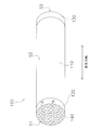
- FIG. 1 Perspective view of separation membrane structure AA sectional view of FIG.
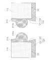
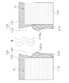
- the figure for explaining the adhesion process of the slurry by the flow-down method The figure for demonstrating a mode that the liquid reservoir of the seeding slurry was formed The figure for demonstrating a mode that the liquid pool of the seeding slurry shrinks
- FIG. 1 is a perspective view of the separation membrane structure 100.
- FIG. 2 is a cross-sectional view taken along the line AA in FIG.
- the separation membrane structure 100 includes a porous support 110, a first glass seal 120, a second glass seal 130, and a separation membrane 140.
- the porous support 110 is formed in a columnar shape.
- the length of the porous support 110 in the longitudinal direction can be 150 to 2000 mm, and the diameter of the porous support 110 in the short direction can be 30 to 220 mm.
- the porous support 110 has a first end surface S1, a second end surface S2, a side surface S3, and a plurality of first through holes TH1.
- the first end surface S1 is provided opposite to the second end surface S2.
- the side surface S3 is a column surface that continues to the outer edge of the first end surface S1 and the outer edge of the second end surface S2.
- the first through hole TH1 penetrates the porous support 110.
- the first through hole TH1 is continuous from the first end surface S1 to the second end surface S2.
- the cross-sectional shape of the first through hole TH1 is circular.
- the inner diameter of the first through hole TH1 can be 1 to 5 mm.
- the porous support 110 is composed of a base material 111, a first support layer 112, and a second support layer 113.
- the base material 111 is formed in a cylindrical shape.
- a plurality of second through holes TH2 are formed in the base material 111.
- the second through hole TH2 penetrates the base material 111.
- the second through hole TH2 is continuous from the first end surface S1 to the second end surface S2.
- the second through hole TH2 exists outside the first through hole TH1.
- the substrate 111 is made of a porous material.
- a ceramic material a metal material, a resin material, or the like can be used.
- alumina Al 2 O 3
- titania TiO 2
- mullite Al 2 O 3 .SiO 2
- cerven and cordierite Mg 2 Al 4 Si 5 O 18
- the base material 111 may contain an inorganic binder.
- an inorganic binder at least one of titania, mullite, easily sinterable alumina, silica, glass frit, clay mineral, and easily sinterable cordierite can be used.
- the porosity of the substrate 111 can be 25% to 50%.
- the average pore diameter of the substrate 111 can be 5 ⁇ m to 25 ⁇ m.
- the porosity and average pore diameter of the substrate 111 can be measured with a mercury porosimeter.
- the average particle diameter of the substrate 111 can be 10 ⁇ m to 100 ⁇ m.
- the “average particle diameter” is an arithmetic average value of the maximum diameters of 30 measurement target particles measured by cross-sectional microstructure observation using a SEM (Scanning Electron Microscope).
- the first support layer 112 is formed on the inner surface 111S of the second through hole TH2 formed in the base material 111. Therefore, the first support layer 112 is formed in a cylindrical shape.
- the first support layer 112 can be made of the same material as the base material 111.
- the thickness of the first support layer 112 can be 10 ⁇ m to 500 ⁇ m.
- the average pore diameter of the first support layer 112 can be 0.005 ⁇ m to 2 ⁇ m.
- the average pore diameter of the first support layer 112 can be measured with a mercury porosimeter.
- the “thickness” of each layer means the height of each layer in a direction (hereinafter referred to as a radial direction) perpendicular to the central axis of the first through hole TH1 extending in the longitudinal direction.
- the second support layer 113 is formed on the inner surface 112S of the first support layer 112. Therefore, the second support layer 113 is formed in a cylindrical shape.
- the inner surface 113S of the second support layer 113 is the inner surface of the first through hole TH1.
- the second support layer 113 can be made of the same material as the base material 111.
- the thickness of the second support layer 113 can be 5 ⁇ m to 300 ⁇ m.
- the average pore diameter of the second support layer 113 can be 0.003 ⁇ m to 0.5 ⁇ m.
- the average pore diameter of the second support layer 113 can be measured with a mercury porosimeter.
- the first glass seal 120 covers the first end face S1.
- sticker 120 is formed so that the opening of the cell C mentioned later may not be obstruct
- the first glass seal 120 suppresses the mixed fluid flowing into the cell C from infiltrating the first end surface S1.
- the first glass seal 120 according to the present embodiment also covers one end of the side surface S3.
- the first glass seal 120 is made of a glass material.
- the first glass seal 120 includes a first seal body 121 and a first extension 122 as shown in FIG.
- the first seal body 121 is disposed on the first end surface S ⁇ b> 1 of the porous support 110.
- the first seal body 121 is formed in a perforated disk shape.
- the first extending part 122 is continuous with the first seal main body part 121.
- the first extending portion 122 is disposed on the inner surface of the first through hole TH1. That is, the first extending portion 122 is a portion of the first glass seal 120 that has entered the first through hole TH1.
- the first extending part 122 is formed in an annular shape.
- the second glass seal 130 covers the second end surface S2. However, the second glass seal 130 is formed so as not to block the opening of the cell C. The second glass seal 130 suppresses the mixed fluid from infiltrating the second end surface S2.
- the second glass seal 130 is made of a glass material.
- 2nd glass seal 130 concerning this embodiment has the 2nd seal body part 131 and the 2nd extension part 132, as shown in FIG.
- the second seal body 131 is disposed on the second end surface S ⁇ b> 2 of the porous support 110.
- the second seal body 131 is formed in a perforated disk shape.
- the second extending part 132 is continuous with the second seal body part 131.
- the second extending portion 132 is disposed on the inner surface of the first through hole TH1. That is, the second extending portion 132 is a portion of the second glass seal 130 that has entered the first through hole TH1.
- the second extending part 132 is formed in an annular shape.
- the separation membrane 140 is formed on the inner surface of the first through hole TH1. Therefore, the separation membrane 140 is formed in a cylindrical shape.
- the space inside the separation membrane 140 is a cell C for circulating the mixed fluid.
- the inner diameter of the cell C can be 1 mm to 5 mm.
- the thickness of the separation membrane 140 is preferably 10 ⁇ m or less, and more preferably 3 ⁇ m or less.
- the pore diameter of the separation membrane 140 is not particularly limited and can be adjusted as appropriate according to the type of membrane.
- the separation membrane 140 is a gas separation membrane, a pervaporation membrane used for the pervaporation method, or a vapor permeable membrane used for the vapor permeation method.
- a separation membrane 140 include known carbon monoxide separation membranes (see, for example, Japanese Patent No. 4006107), helium separation membranes (see, for example, Japanese Patent No. 395833), hydrogen separation membranes (see, for example, Japanese Patent No. 3933907). ), Carbon membrane (for example, see JP2003-286018A), zeolite membrane (for example, see JP2004-66188A), silica membrane (for example, see WO2008 / 050812 pamphlet) Etc.
- a DDR type zeolite membrane is suitable as the separation membrane 140.
- the separation membrane 140 has a first connection part 141 and a second connection part 142.
- the first connection portion 141 is an end portion of the separation membrane 140 on the first glass seal 120 side.
- the first connecting portion 141 is connected to the first extending portion 122 of the first glass seal 120.
- the first connection part 141 is in direct contact with the first extension part 122.
- the first connecting portion 141 can be defined as a region within 2 mm from the tip of the separation membrane 140 on the first glass seal 120 side.
- the second connecting portion 142 is an end portion of the separation membrane 140 on the second glass seal 130 side.
- the second connection part 142 is connected to the second extension part 132 of the second glass seal 130.
- the second connection part 142 is in direct contact with the second extension part 132.
- the second connecting portion 142 can be defined as a region within 2 mm from the tip of the separation membrane 140 on the second glass seal 130 side.
- the first thickness P1 of the first connecting portion 141 is 10 ⁇ m or less.
- the first thickness P1 is preferably 5 ⁇ m or less, and more preferably 3 ⁇ m or less.
- the 2nd thickness P2 of the 2nd connection part 142 is 10 micrometers or less.
- the second thickness P2 is preferably 5 ⁇ m or less, and more preferably 3 ⁇ m or less.
- the first thickness P1 of the first connecting portion 141 is 3.2 times or less the central thickness P3 at the center in the longitudinal direction of the separation membrane 140. That is, the ratio of the first thickness P1 to the central thickness P3 is 3.2 or less.
- the first thickness P1 is preferably not more than 3 times the center thickness P3, and particularly preferably not more than 2.1 times.
- the 2nd thickness P2 of the 2nd connection part 142 is 3.2 times or less of the center thickness P3. That is, the ratio of the second thickness P2 to the central thickness P3 is 3.2 or less.
- the second thickness P2 is preferably not more than 3 times the center thickness P3, and particularly preferably not more than 2.1 times.
- Each of the first thickness P1, the second thickness P2, and the center thickness P3 may be a measurement value obtained by observing a cross section at one place, but a plurality of values obtained by observing a cross section at a plurality of places. It may be an arithmetic average of measured values. Further, each of the first thickness P1, the second thickness P2, and the center thickness P3 may be an arithmetic average of values measured in one section of each of a plurality of cells (for example, 5 cells).
- a molded body of the base material 111 in which a plurality of second through holes TH2 are formed is formed using clay containing a porous material.
- a press molding method or a cast molding method can be used in addition to the extrusion molding method using a vacuum extrusion molding machine.
- the base material 111 is formed by firing the molded body of the base material 111 (for example, 900 ° C. to 1650 ° C., 1 hour to 100 hours).
- a first support layer slurry is prepared by mixing a porous material, an organic binder, a pH adjuster, a surfactant and the like.
- a molded body of the first support layer 112 is formed by a filtration method using the first support layer slurry. Specifically, the first support layer slurry is sucked by the pump from the side surface S3 of the base 111 while supplying the first support layer slurry to the second through hole TH2 of the base 111, so that the first on the inner surface 111S of the base 111 is obtained. A shaped body of the support layer 112 is deposited.
- the first support layer 112 is formed by firing the molded body of the first support layer 112 (eg, 900 ° C. to 1450 ° C., 1 hour to 100 hours).
- a porous material, an organic binder, a pH adjuster, a surfactant and the like are mixed to prepare a second support layer slurry.
- a molded body of the second support layer 113 is formed by a filtration method using the second support layer slurry. Specifically, the second support layer slurry is sucked with a pump from the side surface S3 of the base 111 while supplying the second support layer slurry to the inside of the first support layer 112, so that the second support layer 112 is formed on the inner surface 112S of the first support layer 112. A molded body of the support layer 113 is deposited.
- the second support layer 113 is formed by firing the molded body of the second support layer 113 (for example, 900 ° C. to 1450 ° C., 1 hour to 100 hours). Thereby, the porous support body 110 which has several 1st through-hole TH1 is completed.
- a glass frit is mixed with water and an organic binder to prepare a glass seal slurry.
- a molded body of the first glass seal 120 and the second glass seal 130 is formed by applying a slurry for glass seal to the first end surface S1 and the second end surface S2 of the porous support 110. At this time, a small amount of the glass seal slurry enters each first through hole TH1, so that the molded body of the first extending portion 122 of the first glass seal 120 and the second extending portion 132 of the second glass seal 130 is formed. It is formed.
- first glass seal 120 and the second glass seal 130 are formed by firing the molded body of the first glass seal 120 and the second glass seal 130 (800 to 1000 ° C.).
- a separation membrane 140 is formed on the inner surface of each first through hole TH1 of the porous support 110.
- a zeolite membrane is formed as the separation membrane 140 will be described as an example.
- a seeding slurry is prepared by adding zeolite particles (seed crystals) to a solvent.
- zeolite particles seed crystals
- a solvent for dilution water, ethanol, ethanol aqueous solution, acetone, IPA, or the like can be used.
- water, ethanol and IPA having a viscosity of 1.66 mPa ⁇ s or less are suitable.
- the seeding slurry is adhered to the inner surface of the first through hole TH1 by the flow-down method.
- the porous support 110 is disposed so that the first end surface S1 is lower than the second end surface S2, and the seeding slurry is extracted from the wide-mouth funnel 200 to which the cock 200a is attached.
- 210 is caused to flow from the second end face S2 side into the first through hole TH1.
- the seeding slurry 210 adheres to the inner surface of the first through hole TH1 while flowing down under its own weight. Excess seeding slurry 210 flows out of the first through hole TH1.
- a liquid reservoir 210 a of the seeding slurry 210 is formed in front of the first extension portion 122 of the first glass seal 120, that is, above the first extension portion 122. .
- the seeding slurry 210 is dried by flowing a gas into the first through hole TH1 from the first end face S1 side toward the second end face S2 side.
- the seeding slurry 210 can be dried while reducing the liquid reservoir 210a.
- the liquid reservoir 210a can be more efficiently reduced by turning the porous support 110 upside down so that the second end face S2 is lower than the first end face S1.
- the temperature of the gas is not particularly limited, but can be 10 ° C. to 35 ° C.
- the wind speed is not particularly limited, but can be 0.5 m / s or more.
- the wind speed is preferably 1.0 m / s or more.
- adhesion step and ventilation drying step are preferably repeated a plurality of times in order to uniformly deposit the seeding slurry 210.
- hydrothermal synthesis is performed by immersing the porous support 110 in a pressure resistant container containing the raw material solution.
- the synthesis temperature can be 110 ° C. to 200 ° C., preferably 120 ° C. to 140 ° C.
- the synthesis time can be 1 hour to 100 hours. From the viewpoint of working efficiency and synthesis temperature stability, about 5 to 50 hours is preferable.
- the film thickness can be controlled by “synthesis temperature”, “synthesis time”, and “thickness of seeding slurry 210”. In particular, the ratio of the thickness of the zeolite film adhered to the inner surface of the first through hole TH1. The rate is determined by the ratio of the thickness of the seeding slurry 210.
- the ratio of the first thickness P1 and the second thickness P2 to the central thickness P3 can be reduced. it can.
- the porous support 110 is formed in a columnar shape, but may be formed in a polygonal column shape, for example.
- the porous support 110 has the base 111, the first support layer 112, and the second support layer 113, but the first support layer 112 and the second support layer 113 At least one of them may not be included, and other support layers may be included in addition to the first support layer 112 and the second support layer 113.
- the first glass seal 120 covers a part of the side surface S3.
- the first glass seal 120 may not cover the side surface S3.
- the second glass seal 130 may not cover the side surface S3.
- the seeding slurry is attached to the inner surface of the first through hole TH1 by the flow-down method, but the seeding slurry can also be attached by, for example, the dip method.
- the dipping method is a method of attaching the seeding slurry to the inner surface of the first through hole TH1 by raising the seeding slurry in the first through hole TH1 and then lowering it.
- the seeding slurry is attached by the dip method, since a liquid pool is formed on the lower end side of the porous support 110, it is used for seeding while reducing the liquid pool by ventilating from the lower end side of the porous support 110.
- the slurry can be dried.
- the first thickness P1 of the first connection portion 141 of the separation membrane 140 is 3.2 times or less the center thickness P3, and the second thickness P2 of the second connection portion 142 is the center thickness P3.
- a glass frit was mixed with water and an organic binder to prepare a glass seal slurry.
- zeolite particles were added to the solvents shown in Table 1 to prepare a seeding slurry.
- the viscosity of the solvent used was as shown in Table 1.
- the porous support was arranged vertically, and the seeding slurry was adhered to the inner surface of each through hole.
- the seeding slurry was attached by the dip method, and sample No. Except 2, the seeding slurry was attached by the flow-down method.
- the seeding slurry flow-down step and the seeding slurry drying step were repeated 1 to 3 times.
- a sol for film formation is placed and heat treatment (hydrothermal synthesis) : 130 ° C., 24 hours) to form a high silica DDR type zeolite membrane.
- the alumina support was washed and dried at 80 ° C. for 12 hours or more.
- the alumina support was heated to 450 ° C. in an electric furnace and held for 50 hours to burn and remove 1-adamantanamine.
- the thickness of the part namely, 1st connection part
- the thickness of the part within 2 mm namely, 2nd connection part
- the measured value was an average value for 5 cells in each part.
- the measurement results are as shown in Table 1.
Landscapes
- Chemical & Material Sciences (AREA)
- Chemical Kinetics & Catalysis (AREA)
- Inorganic Chemistry (AREA)
- Engineering & Computer Science (AREA)
- Life Sciences & Earth Sciences (AREA)
- Geology (AREA)
- Manufacturing & Machinery (AREA)
- General Life Sciences & Earth Sciences (AREA)
- Organic Chemistry (AREA)
- Analytical Chemistry (AREA)
- General Chemical & Material Sciences (AREA)
- Oil, Petroleum & Natural Gas (AREA)
- Crystallography & Structural Chemistry (AREA)
- Materials Engineering (AREA)
- Separation Using Semi-Permeable Membranes (AREA)
Abstract
Priority Applications (4)
| Application Number | Priority Date | Filing Date | Title |
|---|---|---|---|
| CN201580060731.8A CN106999864B (zh) | 2014-12-09 | 2015-12-07 | 分离膜结构体及其制造方法 |
| DE112015005518.5T DE112015005518T5 (de) | 2014-12-09 | 2015-12-07 | Trennmembranstruktur und Verfahren zu deren Herstellung |
| JP2016563667A JP6767876B2 (ja) | 2014-12-09 | 2015-12-07 | 分離膜構造体及びその製造方法 |
| US15/583,021 US10213749B2 (en) | 2014-12-09 | 2017-05-01 | Separation membrane structure and method for manufacturing same |
Applications Claiming Priority (2)
| Application Number | Priority Date | Filing Date | Title |
|---|---|---|---|
| JP2014-249096 | 2014-12-09 | ||
| JP2014249096 | 2014-12-09 |
Related Child Applications (1)
| Application Number | Title | Priority Date | Filing Date |
|---|---|---|---|
| US15/583,021 Continuation US10213749B2 (en) | 2014-12-09 | 2017-05-01 | Separation membrane structure and method for manufacturing same |
Publications (1)
| Publication Number | Publication Date |
|---|---|
| WO2016093192A1 true WO2016093192A1 (fr) | 2016-06-16 |
Family
ID=56107376
Family Applications (1)
| Application Number | Title | Priority Date | Filing Date |
|---|---|---|---|
| PCT/JP2015/084267 Ceased WO2016093192A1 (fr) | 2014-12-09 | 2015-12-07 | Structure de membrane de séparation et son procédé de fabrication |
Country Status (5)
| Country | Link |
|---|---|
| US (1) | US10213749B2 (fr) |
| JP (1) | JP6767876B2 (fr) |
| CN (1) | CN106999864B (fr) |
| DE (1) | DE112015005518T5 (fr) |
| WO (1) | WO2016093192A1 (fr) |
Cited By (3)
| Publication number | Priority date | Publication date | Assignee | Title |
|---|---|---|---|---|
| WO2022163064A1 (fr) * | 2021-01-28 | 2022-08-04 | 日本碍子株式会社 | Corps composite à membrane de séparation et procédé de production pour corps composite à membrane de séparation |
| DE112023000478T5 (de) | 2022-02-08 | 2024-10-17 | Ngk Insulators, Ltd. | Trennmembrankomplex, Mischgastrennvorrichtung und Verfahren zum Herstellen eines Trennmembrankomplexes |
| WO2025197200A1 (fr) * | 2024-03-18 | 2025-09-25 | 日本碍子株式会社 | Composite à membrane de séparation et procédé de production d'un composite à membrane de séparation |
Families Citing this family (1)
| Publication number | Priority date | Publication date | Assignee | Title |
|---|---|---|---|---|
| JP7590869B2 (ja) | 2018-09-28 | 2024-11-27 | 日本碍子株式会社 | 支持体、ゼオライト膜複合体、ゼオライト膜複合体の製造方法、および、分離方法 |
Citations (7)
| Publication number | Priority date | Publication date | Assignee | Title |
|---|---|---|---|---|
| JPS62129104A (ja) * | 1985-11-28 | 1987-06-11 | Ngk Insulators Ltd | セラミック管状フィルターの製造法 |
| JP2001300273A (ja) * | 2000-04-27 | 2001-10-30 | Ngk Insulators Ltd | セラミックフィルタ |
| WO2009113715A1 (fr) * | 2008-03-12 | 2009-09-17 | 日本碍子株式会社 | Procédé de fabrication d'une structure pourvue d'une membrane à zéolite de type ddr |
| JP2009226306A (ja) * | 2008-03-21 | 2009-10-08 | Ngk Insulators Ltd | セラミックフィルタ及びナノ濾過膜の製造方法 |
| JP2010110704A (ja) * | 2008-11-07 | 2010-05-20 | Ngk Insulators Ltd | 分離膜の製造方法 |
| JP2013034994A (ja) * | 2010-02-25 | 2013-02-21 | Ngk Insulators Ltd | 分離膜の欠陥検出方法 |
| WO2013136869A1 (fr) * | 2012-03-16 | 2013-09-19 | 日本碍子株式会社 | Processus de production d'une membrane de séparation, processus de production d'un composite pour membrane de séparation et composite pour membrane de séparation |
Family Cites Families (10)
| Publication number | Priority date | Publication date | Assignee | Title |
|---|---|---|---|---|
| JP2006088079A (ja) * | 2004-09-27 | 2006-04-06 | Bussan Nanotech Research Institute Inc | 管端部接続体 |
| JP4607634B2 (ja) * | 2005-03-22 | 2011-01-05 | 日本碍子株式会社 | セラミックフィルタ |
| JP2010099559A (ja) * | 2008-10-22 | 2010-05-06 | Ngk Insulators Ltd | 分離膜の製造方法 |
| WO2010070992A1 (fr) * | 2008-12-19 | 2010-06-24 | 日本碍子株式会社 | Procédé de séparation d'un mélange liquide et dispositif de séparation d'un mélange liquide |
| EP2409758A4 (fr) * | 2009-03-16 | 2013-07-31 | Ngk Insulators Ltd | Structure dotée d'une membrane de séparation zéolitique, procédé de production associé, procédé de séparation de fluides mixtes et dispositif de séparation de fluides mixtes |
| US8101010B2 (en) * | 2009-05-28 | 2012-01-24 | Corning Incorporated | Gas separation module |
| JP5624542B2 (ja) * | 2009-07-10 | 2014-11-12 | 日本碍子株式会社 | 炭素膜の製造方法、炭素膜、及び分離装置 |
| JP2012040549A (ja) * | 2010-07-22 | 2012-03-01 | Ngk Insulators Ltd | シリカ膜、及びその製造方法 |
| WO2012128217A1 (fr) * | 2011-03-22 | 2012-09-27 | 日本碍子株式会社 | Structure de membrane de séparation en céramique en forme de nid d'abeilles |
| BR112014008629A2 (pt) | 2011-10-11 | 2017-04-18 | Ngk Insulators Ltd | filtro de cerâmica |
-
2015
- 2015-12-07 WO PCT/JP2015/084267 patent/WO2016093192A1/fr not_active Ceased
- 2015-12-07 CN CN201580060731.8A patent/CN106999864B/zh active Active
- 2015-12-07 DE DE112015005518.5T patent/DE112015005518T5/de active Pending
- 2015-12-07 JP JP2016563667A patent/JP6767876B2/ja active Active
-
2017
- 2017-05-01 US US15/583,021 patent/US10213749B2/en active Active
Patent Citations (7)
| Publication number | Priority date | Publication date | Assignee | Title |
|---|---|---|---|---|
| JPS62129104A (ja) * | 1985-11-28 | 1987-06-11 | Ngk Insulators Ltd | セラミック管状フィルターの製造法 |
| JP2001300273A (ja) * | 2000-04-27 | 2001-10-30 | Ngk Insulators Ltd | セラミックフィルタ |
| WO2009113715A1 (fr) * | 2008-03-12 | 2009-09-17 | 日本碍子株式会社 | Procédé de fabrication d'une structure pourvue d'une membrane à zéolite de type ddr |
| JP2009226306A (ja) * | 2008-03-21 | 2009-10-08 | Ngk Insulators Ltd | セラミックフィルタ及びナノ濾過膜の製造方法 |
| JP2010110704A (ja) * | 2008-11-07 | 2010-05-20 | Ngk Insulators Ltd | 分離膜の製造方法 |
| JP2013034994A (ja) * | 2010-02-25 | 2013-02-21 | Ngk Insulators Ltd | 分離膜の欠陥検出方法 |
| WO2013136869A1 (fr) * | 2012-03-16 | 2013-09-19 | 日本碍子株式会社 | Processus de production d'une membrane de séparation, processus de production d'un composite pour membrane de séparation et composite pour membrane de séparation |
Cited By (4)
| Publication number | Priority date | Publication date | Assignee | Title |
|---|---|---|---|---|
| WO2022163064A1 (fr) * | 2021-01-28 | 2022-08-04 | 日本碍子株式会社 | Corps composite à membrane de séparation et procédé de production pour corps composite à membrane de séparation |
| JPWO2022163064A1 (fr) * | 2021-01-28 | 2022-08-04 | ||
| DE112023000478T5 (de) | 2022-02-08 | 2024-10-17 | Ngk Insulators, Ltd. | Trennmembrankomplex, Mischgastrennvorrichtung und Verfahren zum Herstellen eines Trennmembrankomplexes |
| WO2025197200A1 (fr) * | 2024-03-18 | 2025-09-25 | 日本碍子株式会社 | Composite à membrane de séparation et procédé de production d'un composite à membrane de séparation |
Also Published As
| Publication number | Publication date |
|---|---|
| CN106999864B (zh) | 2020-01-14 |
| US20170232401A1 (en) | 2017-08-17 |
| DE112015005518T5 (de) | 2017-09-21 |
| US10213749B2 (en) | 2019-02-26 |
| JPWO2016093192A1 (ja) | 2017-09-14 |
| CN106999864A (zh) | 2017-08-01 |
| JP6767876B2 (ja) | 2020-10-14 |
Similar Documents
| Publication | Publication Date | Title |
|---|---|---|
| JP6523516B2 (ja) | ゼオライト膜の再生方法 | |
| US11135553B2 (en) | Porous support, method for manufacturing porous support, separation membrane structure, and method for manufacturing separation membrane structure | |
| EP2832429B1 (fr) | Corps en céramique poreux en forme de nid d'abeilles, son procédé de fabrication, et structure à membrane de séparation en céramique en forme de nid d'abeilles | |
| US20140291245A1 (en) | Ceramic separation filter and dehydration method | |
| US9555377B2 (en) | Ceramic separation membrane and dehydration method | |
| AU2007263408A2 (en) | Ceramic filter | |
| JP6301313B2 (ja) | ゼオライト膜の製造方法 | |
| JP6767876B2 (ja) | 分離膜構造体及びその製造方法 | |
| JP6436974B2 (ja) | モノリス型分離膜構造体及びモノリス型分離膜構造体の製造方法 | |
| CN105073687B (zh) | 磷酸铝‑金属氧化物接合体及其制造方法 | |
| JP2016190200A (ja) | ゼオライト膜の製造方法 | |
| JP6490665B2 (ja) | モノリス型分離膜構造体、モノリス型分離膜構造体の製造方法及び脱水方法 | |
| JP6702884B2 (ja) | ガス分離方法 | |
| WO2016104048A1 (fr) | Procédé de séparation de gaz | |
| JP6636932B2 (ja) | 膜構造体及びその製造方法 | |
| WO2022163064A1 (fr) | Corps composite à membrane de séparation et procédé de production pour corps composite à membrane de séparation | |
| JP6421139B2 (ja) | モノリス型分離膜構造体 | |
| JP6559146B2 (ja) | 分離膜構造体の製造方法 | |
| JP2009189941A (ja) | セラミックフィルタの製造方法 | |
| JP2016190201A (ja) | 分離膜構造体とその製造方法 | |
| JP2011194283A (ja) | シリカ膜の処理方法 | |
| JP2017177079A (ja) | モノリス型分離膜構造体 |
Legal Events
| Date | Code | Title | Description |
|---|---|---|---|
| 121 | Ep: the epo has been informed by wipo that ep was designated in this application |
Ref document number: 15867396 Country of ref document: EP Kind code of ref document: A1 |
|
| ENP | Entry into the national phase |
Ref document number: 2016563667 Country of ref document: JP Kind code of ref document: A |
|
| WWE | Wipo information: entry into national phase |
Ref document number: 112015005518 Country of ref document: DE |
|
| 122 | Ep: pct application non-entry in european phase |
Ref document number: 15867396 Country of ref document: EP Kind code of ref document: A1 |